AUMATIC AC 01.1/ACExC 01.1, Profibus DP, Operation and Setting · Actuator controls AUMATIC AC...
112
Actuator controls AUMATIC AC 01.1/ACExC 01.1 Manual Operation and setting Control: Parallel à Profibus DP Profibus DP with FO Modbus Modbus with FO DeviceNet Foundation Fieldbus
Transcript of AUMATIC AC 01.1/ACExC 01.1, Profibus DP, Operation and Setting · Actuator controls AUMATIC AC...

Actuator controls
AUMATIC AC 01.1/ACExC 01.1
Manual Operation and setting
Control:
Parallel
� Profibus DP
Profibus DP with FO
Modbus
Modbus with FO
DeviceNet
Foundation Fieldbus

Table of contents Page
1 Safety instructions . . . . . . . . . . . . . . . . . . . . . . . . . . . . . . . . . . . 5
1.1 General notes regarding safety 51.2 Range of application 61.3 Warnings and symbols 6
2 Identification . . . . . . . . . . . . . . . . . . . . . . . . . . . . . . . . . . . . . . . 7
2.1 Name plate 72.2 Short description 8
3 Operation . . . . . . . . . . . . . . . . . . . . . . . . . . . . . . . . . . . . . . . . 9
3.1 Local operation 93.2 Operation from REMOTE 93.3 Menu navigation via push buttons (for settings and indications) 103.3.1 Short overview: functions of the push buttons 103.3.2 Structural design and navigation 113.4 Operation and setting via AUMA COM-AC programming software 123.4.1 Operation setting via COM-AC 123.5 Password change 133.6 Language change in the display 143.7 LCD contrast setting of the display (applies only to controls with green display) 14
4 Indications . . . . . . . . . . . . . . . . . . . . . . . . . . . . . . . . . . . . . . . 15
4.1 Status indications in the display 154.1.1 Status indication S0/S6 – operation 154.1.2 Status indication S4 – torque 164.2 Torque indication: edit 164.3 Electronic name plate 174.3.1 Display indication: enable view 174.3.2 Electronic name plate: view 174.4 Indication lights/LEDs 194.4.1 Standard indication 194.4.2 Configuration of the signals: view/edit 204.4.3 Blinking behaviour of indication lights/LEDs: view/edit 21
5 Signals . . . . . . . . . . . . . . . . . . . . . . . . . . . . . . . . . . . . . . . . . 22
5.1 Signals via fieldbus 225.1.1 Configuration for process representation input: view 225.1.2 Configuration of adjustable (user-definable) signals: view 235.1.3 Configuration of fault signals: view 255.1.4 Percent/per mil coding for transmission values: view 265.2 Feedback via output contacts (binary) - (option) 275.2.1 Configuration for output contacts 1 to 5: view/edit 275.2.2 Configuration for alarm contacts (collective fault signal): view/edit 295.2.3 Output contacts 1 to 5: use as running indication (blinker) 305.3 Feedback signals (analogue) - (option) 315.3.1 Position transmitter/actual position source (E2): view 315.3.2 Source of the torque signal E6: view 325.3.3 Feedback signals (configuration) via analogue output 1: view 32
2
Actuator controlsAUMATIC AC 01.1/ACExC 01.1 Profibus DP Manual
Read operation instructions first. Observe safety instructions.
Reference documents:. Operation instructions (assembly, operation, commissioning) for actuator. Manual (Fieldbus device integration) AUMATIC AC 01.1/ACExC 01.1 Profibus DP
Can be downloaded from the Internet (www.auma.com) or ordered directly from AUMA (addresses from page ).

Page5.3.4 Signal range at the analogue output 1: view/edit 335.3.5 Feedback signals (configuration) via analogue output 2: view 345.3.6 Signal range at the analogue output 2: view/edit 34
6 Operation mode . . . . . . . . . . . . . . . . . . . . . . . . . . . . . . . . . . . . 35
6.1 Operation mode OFF 356.2 Operation mode LOCAL 366.2.1 Push-to-run operation or self-retaining: set for operation mode LOCAL 366.3 Operation mode REMOTE 376.3.1 Push-to-run operation or self-retaining: set for operation mode REMOTE 376.4 Operation mode EMERGENCY 386.4.1 Operation mode (type of duty) activation for an EMERGENCY operation 386.4.2 EMERGENCY operation: switch on or off/signal behaviour definition 396.4.3 Actuator behaviour definition in case of an EMERGENCY operation 396.4.4 EMERGENCY position definition 406.4.5 Motor protection and/or torque switching: by-pass 406.5 Operation mode FAILURE 416.5.1 Failure behaviour: switch on or off 416.5.2 Source for initiation (failure source): set for failure operation 426.5.3 Actuator reaction (failure position): set on loss of signal 426.5.4 Preset position definition 436.5.5 Failure delay time setting 436.5.6 Failure behaviour on bus communication loss 44
7 Functions . . . . . . . . . . . . . . . . . . . . . . . . . . . . . . . . . . . . . . . . 45
7.1 Type of seating: check/edit end positions 457.2 Torque switching: check/set 467.3 Limit switching setting 477.4 Intermediate positions (option) 487.4.1 Display indication: enable view 487.4.2 Intermediate positions: switch on or off 497.4.3 Intermediate position definition 497.4.4 Operation behaviour = actuator behaviour definition 507.4.5 Intermediate positions: set the signalling 507.5 Intermediate positions with multiport valve function (option) 527.5.1 Check: Multiport valve function availablequestion 527.5.2 Check: Positioner active? 537.5.3 Display indication: enable view 537.5.4 Intermediate positions: switch on or off 537.5.5 Intermediate position setting 537.5.6 Operation behaviour = actuator behaviour definition 547.5.7 Intermediate positions signalling 547.5.8 Intermediate positions in LOCAL: direct approach without stopping 547.6 Positioner (operation mode SETPOINT MODE) 557.6.1 Adaptive behaviour: switch on or off 557.6.2 Overrun (inner dead band): set manually 567.6.3 Max. error variable (outer dead band): set manually 577.6.4 Dead time setting 577.6.5 Closing fully/opening fully (end position tolerance for setpoint E1) 587.6.6 Open-close duty (REMOTE MODE) and modulating duty (SETPOINT MODE) selection 587.6.7 Source of setpoint E1: view 597.6.8 Input range of setpoint 1: view/edit 607.7 Process controller (option) 617.7.1 Setting procedure 627.7.2 Process controller activation (Check: Process controller available?) 627.7.3 Proportional gain Kp setting 637.7.4 Reset time Ti setting 637.7.5 Rate time Td setting 64
3
Actuator controlsManual AUMATIC AC 01.1/ACExC 01.1 Profibus DP
Page7.7.6 Derivative gain Kd setting 647.7.7 Internal process setpoint setting 657.7.8 Behaviour on loss of the process setpoint (wire break monitoring) 667.7.9 Inverse operation setting 667.7.10 Travel limitation 677.7.11 Reaction monitoring setting 687.7.12 Input range of process setpoint E1: view 697.7.13 Input range of process variable E4: view/edit 697.8 Stepping mode (option) 707.8.1 Display indication: enable view 707.8.2 Stepping mode: switch on or off 717.8.3 Stepping range setting (start and end of stepping mode) 717.8.4 ON and OFF times setting 727.9 Local controls enable function (option) 737.9.1 Selector switch functions: enable/disable 737.10 EMERGENCY STOP function (option) 757.10.1 Description of the functions 757.10.2 Feedback signals on the display 767.10.3 Feedback signals setting via output contacts 767.10.4 Feedback signal setting via LEDs 767.11 Profibus DP interface (option) 777.11.1 Bus address setting (Slaveaddress) 777.12 Redundant bus connection with component redundancy (option) 787.12.1 Configuration check for the second fieldbus interface 787.12.2 Second fieldbus interface setting 787.13 Profibus DP-V1 services (option) 797.14 External inputs for bus (option) 807.14.1 Signals assignation for operation commands 807.15 Combination fieldbus/standard interface (option) 837.16 Monitoring and failure functions 847.16.1 Torque monitoring 847.16.2 Motor protection (thermal monitoring) 857.16.3 Monitoring of the max. number of starts per hour and max. running time per hour 867.16.4 Operating time monitoring 887.16.5 Reaction monitoring 897.16.6 Phase failure monitoring 90
8 Corrective action . . . . . . . . . . . . . . . . . . . . . . . . . . . . . . . . . . . . 91
8.1 Fault indications and warning indications 918.1.1 Status indication S0 – faults and warnings 918.1.2 Status indication S1 – fault 928.1.3 Status indication S2 – warnings 928.1.4 Status indication S3 – causes for not ready remote 948.2 Diagnostics 958.2.1 Operating data logging 958.2.2 Diagnostic indications (D) via the display 978.3 Troubleshooting 1078.3.1 Problems with position feedback/indication E2 (from actuator) 1078.3.2 Display hardly readable or illegible 1078.3.3 Actuator does not run 1078.3.4 Actuator does only operate from local 1078.3.5 Actuator is not switched off by limit seating in direction CLOSE or OPEN 107
Index . . . . . . . . . . . . . . . . . . . . . . . . . . . . . . . . . . . . . . . . . . 108
Parameter index and indications on the display . . . . . . . . . . . . . . . . . . 109
Addresses . . . . . . . . . . . . . . . . . . . . . . . . . . . . . . . . . . . . . . . 110
4
Actuator controlsAUMATIC AC 01.1/ACExC 01.1 Profibus DP Manual
1 Safety instructions
1.1 General notes regarding safety
5
Actuator controlsManual AUMATIC AC 01.1/ACExC 01.1 Profibus DP
Standards/directives AUMA products are designed and manufactured in compliance with recog-nised standards and directives. This is certified in a declaration of incorpora-tion and a declaration of conformity.The end user or the contractor must ensure that all requirements withrespect to assembly, electrical connection, and commissioning at the placeof installation are met. They include among others:. Standards and directives such as: EN 60079 “Electrical apparatus for
explosive gas atmospheres"Part 14: Electrical installations in hazardous areas (other than mines).Part 17: Inspection and maintenance of electrical installations in hazard-ous areas (other than mines).. Applicable configuration directives for fieldbus applications.
Safety instructions/warnings
All personnel working with this device must be familiar with the safety andwarning instructions in this manual and observe the instructions given.Safety instructions and warning signs on the device must be observed toavoid personal injury or property damage.
Qualification of staff Assembly, electrical connection, commissioning, operation, and maintenancemust be carried out exclusively by suitably qualified personnel authorised by theend user or contractor of the plant.Prior to working on this product, the staff must have thoroughly read and under-stood these instructions and, furthermore, know and observe officially recog-nised rules regarding occupational health and safety.Work performed in potentially explosive atmospheres is subject to special regu-lations which have be observed. The end user or contractor of the plant areresponsible for respect and control of these regulations, standards, and laws.
Commissioning Prior to commissioning, it is important to check that all settings are in com-pliance with the requirements of the application. Incorrect settings mightpresent a danger to the application, e.g. cause damage to the valve or theinstallation.The manufacturer will not be held liable for any consequential damage. Suchrisk lies entirely with the user.
Safe operation Prerequisites for safe and smooth operation:. Correct transport, proper storage, mounting and installation, as well ascareful commissioning.. Exclusively operate the device if it is in perfect condition while observingthese instructions.. Immediately inform about any faults and damage and allow for correctivemeasures.. Observe recognised rules for occupational health and safety.
Protective measures The end user or the contractor are responsible for implementing requiredprotective measures on site, such as enclosures, barriers, or personalsafety equipment for the staff.
Maintenance Any device modification requires the consent of the manufacturer.

1.2 Range of application
AUMA actuator controls are exclusively designed for the operation of AUMAactuators.
Other applications require explicit (written) confirmation by the manufacturer.
The following applications are not permitted, e.g.:
. motor activation. pump activation
No liability can be assumed for inappropriate or unintended use.
Observance of these operation instructions is considered as part of thedevice’s designated use.
1.3 Warnings and symbols
The following references and symbols are used in these instructions:
Potentially hazardous situation. Failure to observe this warning may result inproperty damage.
Information The term Information preceding the text indicates important notes andinformation.
For assembly, operation, and commissioning, observe the additional safetyand warning instructions of the reference documents (page 2).
Symbol for CLOSED.
Symbol for OPEN.
� Via the menu to parameterDescribes the path within the menu to the parameter. By using the push but-tons of the local controls you may quickly find the desired parameter in thedisplay.
� Description of the parameter settings/indicationsDescribes the setting/viewing possibilities of a parameter.
� Step by stepProvides a detailed description of each step for setting/viewing the parame-ter.
6
Actuator controlsAUMATIC AC 01.1/ACExC 01.1 Profibus DP Manual
NOTICE

2 Identification
2.1 Name plate
Each device is equipped with a name plate (figure 1).
Identification data on the controls’ name plate:
Type and size These instructions apply to the following controls types:Type: AC = AUMATIC actuator controlsSize: 01.1
Commission number An order-specific commission number is assigned to each device. You canuse this number to download the wiring diagram, inspection records and fur-ther information from the Internet (http://www.auma.com).
Wiring diagram/control Controlling the actuator controls is performed via a Profibus DP interface,if the 11th position in the ACP wiring diagram contains the letter S, T, U, R,or P. Example: ACP 11F1-2M0—S000.
The actuator controls are designed for the Non-Intrusive version (refer alsoto page 8), if the 7th position in the ACP wiring diagram contains the figureM, e.g.: ACP 11F1-2M0-S000.
7
Actuator controlsManual AUMATIC AC 01.1/ACExC 01.1 Profibus DP
1 Type and size of the controls2 Commission number3 Wiring diagram/control
Figure 1
1 Name plate controls
aum
a
AC 01.1Com No: 1309595
ACP M S:
P:1,5kW
No: 0902MA97286KMS: TP180/001
11F1-2 0-- 0003 ~ 400V IP67Control: RS 485
12
3
Figure 2

2.2 Short description
Actuator controls The AUMATIC actuator controls is used to operate AUMA actuators and issupplied ready for use.The controls can be mounted directly to the actuator but also separately ona wall bracket.The functions of the AUMATIC controls include standard valve control inOPEN - CLOSE duty, positioning, process control, logging of operating data,diagnostic functions right through control via fieldbus.
Local controls/COM-AC/fieldbus
Operation, setting, and display can be performed on site directly at the con-trols or alternatively from REMOTE via a fieldbus interface.On site it is possible to. operate the actuator via the local controls (push buttons and display) and
perform settings (contents of these instructions).. read in or out data or modify and save settings via the AUMA COM-ACprogramming software (option), using a computer (laptop or PC).Depending on the version, the connection between computer andAUMATIC can be made with cable (infra-red interface) or without cable(Bluetooth interface) (not included in these instructions).
Intrusive – Non-Intrusive Intrusive version:. Limit and torque setting is performed via switches in the actuator.Non-Intrusive version:. Limit and torque setting is performed via the controls, actuator and con-
trols housings do not have to be opened.For this purpose, the actuator is equipped with an MWG (magnetic limitand torque transmitter), also supplying analogue torque feedback sig-nals/torque indication.
8
Actuator controlsAUMATIC AC 01.1/ACExC 01.1 Profibus DP Manual

3 Operation
3.1 Local operation
The local operation of the actuator is performed using the push buttons(figure 3).
� Set selector switch (5) to position Local control (LOCAL).
The actuator can now be operated using the push buttons (1 – 3).
1. Run actuator in direction OPEN: Press push button (1).2. Stop actuator: Press push button (2).3. Run actuator in direction CLOSE: Press push button (3).
Information The OPEN - CLOSE operation commands can be given either inpush-to-run operation or in the self-retaining mode.
3.2 Operation from REMOTE
� Set selector switch to position Remote control (REMOTE).
Now, it is possible to operate the actuator by remote control via thefieldbus.
Information . Refer to page 58 to select between REMOTE MODE (open-close duty)and SETPOINT MODE (modulating duty).. The FAILURE MODE and EMERGENCY MODE operation modes are setvia parameters.
9
Actuator controlsManual AUMATIC AC 01.1/ACExC 01.1 Profibus DP
1 Push button OPEN 4 Push button Reset2 Push button STOP 5 Selector switch3 Push button CLOSE 6 Indication lights/LEDs
0
II
0
II
14 1
2
3
5
Figure 3

3.3 Menu navigation via push buttons (for settings and indications)
The push buttons of the local controls (figure 4) are used to view, edit, andshow various indications on the display.
� Set selector switch (5) to position 0 (OFF).
Now, settings and indications can be performed via the push buttons (1 – 4).
3.3.1 Short overview: functions of the push buttons
10
Actuator controlsAUMATIC AC 01.1/ACExC 01.1 Profibus DP Manual
1
6
1
2
3
4
5
�
�
�
C
Figure 4
1 Push button� 4 Push button C2 Push button� 5 Selector switch
3 Push button � 6 Display
0
II
Pushbuttons
Functions
��
Scrolling within a group
(The triangles� in the display show the direction of scrolling.)
Change values
Enter figures from 0 to 9
� Confirm the selection to go to a new menu/subgroup.
C
Cancel process
Return to previous display: press briefly
Change to another group (S, M, D)
- press for approx. 3 seconds until group M0 is displayed.- hold down for more than 3 seconds until group D0 is displayed
(thereby, group M is skipped).
Table 1

3.3.2 Structural design and navigation
The indications on the display are divided into 3 groups:. Group S = status indications. Group M = menu (settings). Group D = diagnostic indicationsThe active group is displayed on the top right corner of the display.
Change groups Change from group S to group M:� Press C push button and hold it down for approx. 3 seconds until group
M0 appears.
Change from group S to group D:� Press C push button and hold it down until group D0 appears
(group M is hereby skipped).
Change from any group M or D back to group S:� Briefly press C.
Scrolling � Press��:The triangles� in the top left corner of the display indicate the possiblescrolling direction (within one group) of scrolling.
Enter the password In the menu (group M), the settings are protected by a password.To change the parameters, a password must first be entered.The following default password is set in the factory: 0000.
After selecting EDIT, the following is displayed:
1. Select figures 0 to 9: Press��.2. Move to the next position: Press � .3. Repeat steps 1 and 2 for all four digits.4. To cancel a process: Press C.
Information If no input is received over a longer period of time (approx. 10 min), the con-trols automatically returns to the status indication S0.
11
Actuator controlsManual AUMATIC AC 01.1/ACExC 01.1 Profibus DP
ENTER PASSWORD
0 * * *
� :EDIT �:OK C:ESC
OFF S0
OPEN POSITION
E2 100%
M0
M0
OFF S0
OPEN POSITION
E2 100%

3.4 Operation and setting via AUMA COM-AC programming software
Data from the actuator can easily be imported, exported and settingschanged and saved using the AUMA COM-AC programming software(option) in combination with a computer.Depending on the version, the connection between computer and AUMATICcan be performed with cable (infra-red interface) or without cable (Bluetoothinterface) (not included in these instructions) .
3.4.1 Operation setting via COM-ACThe COM-AC software can transmit the operation commands OPEN, STOP,CLOSE to the actuator.
� Via the menu to parameter:MAIN MENU (M0)
SETTINGS (M1)
COM-AC CONTROL (M1P0)
LOCAL CLIENT (M1P10)
Default value: REMOTE AND LOCAL
Description of the parameter settings:
REMOTE AND LOCAL
The actuator can be operated in selector switch position LOCAL CONTROLor REMOTE CONTROL via the COM-AC with the OPEN, STOP, CLOSEcommands.
LOCAL CONTROL ONLY
The actuator can be operated in selector switch position LOCAL CONTROL viathe COM-AC with the OPEN, STOP, CLOSE commands.No operation control is possible in selector switch position REMOTE CONTROL.
12
Actuator controlsAUMATIC AC 01.1/ACExC 01.1 Profibus DP Manual
3
1 2
Figure 5
1 Infra-red interface 2 Bluetooth interface (option)3 Bluetooth LED
EDIT M1P10
LOCAL CLIENT
REMOTE AND LOCAL
� :EDIT �:OK C:ESC

3.5 Password change
The following default password is set in the factory: 0000.
� Via the menu to parameter:MAIN MENU (M0)
SETTINGS (M1)
CHANGE PASSWORD (M1D)
� Step by step:1. Setting the selector switch to position 0 (OFF).
2. Press C and hold it down for approx 3 seconds.Display indicates:
3. Press�.Display indicates:
4. Press � .Display indicates:
5. Select CHANGE PASSWORD (M1D) using�.Display indicates:
6. Press � .Display indicates:
7. Enter password (see page 11).
13
Actuator controlsManual AUMATIC AC 01.1/ACExC 01.1 Profibus DP
MAIN MENU M0
LANGUAGE/CONTRAST
SETTINGS
OPERATIONAL DATA
MAIN MENU M1
LANGUAGE/CONTRAST
�SETTINGS
OPERATIONAL DATA
0
II
SETTINGS M10
SET LIMIT SWITCHES
SEATING MODE
TORQUE
SETTINGS M1D
PROFIBUS DP 1
INTERMED. POSITION
CHANGE PASSWORD
CHANGE PASSWORD M1D0
PASSWORD
0000
�:EDIT C:ESC

3.6 Language change in the display
� Via the menu to parameter:MAIN MENU (M0)
LANGUAGE/CONTRAS (M00)
LANGUAGE (M010)
Default value: ENGLISH
Setting range: GERMAN, PORTUGUESE, ITALIAN, SPANISH,
FRENCH, ENGLISH, TUERKCE, POLSKI, MAGYAR
3.7 LCD contrast setting of the display (applies only to controls with green display)
To improve the legibility of the display under unfavourable lighting condi-tions, the contrast may be adjusted.This setting is only possible for green displays. The contrast setting has noeffect on the blue display.
� Via the menu to parameter:MAIN MENU (M0)
LANGUAGE/CONTRAST M00)
LCD CONTRAST (M011)
Default value: 80 %
Setting range: 0 % to 100 %
Information Alternatively, the LCD contrast can be set as follows:1. Press C and hold it down.
The menus S, M, D are skipped.After approximately 10 seconds, the LED display will continuouslychange from bright to dark and vice versa.
2. Release push buttonThe current brightness level is saved.
14
Actuator controlsAUMATIC AC 01.1/ACExC 01.1 Profibus DP Manual
EDIT M010
LANGUAGE
ENGLISH
� :EDIT �:OK C:ESC
EDIT M011
LCD CONTRAST
30 %
� :EDIT �:OK C:ESC
4 Indications
4.1 Status indications in the display
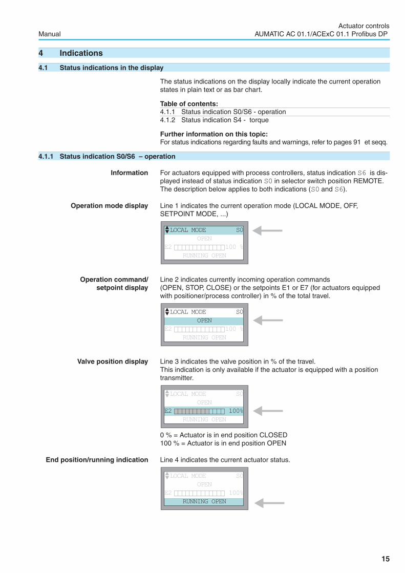
The status indications on the display locally indicate the current operationstates in plain text or as bar chart.
Table of contents:4.1.1 Status indication S0/S6 - operation4.1.2 Status indication S4 - torque
Further information on this topic:For status indications regarding faults and warnings, refer to pages 91 et seqq.
4.1.1 Status indication S0/S6 – operation
Information For actuators equipped with process controllers, status indication S6 is dis-played instead of status indication S0 in selector switch position REMOTE.The description below applies to both indications (S0 and S6).
Operation mode display Line 1 indicates the current operation mode (LOCAL MODE, OFF,SETPOINT MODE, ...)
Operation command/setpoint display
Line 2 indicates currently incoming operation commands(OPEN, STOP, CLOSE) or the setpoints E1 or E7 (for actuators equippedwith positioner/process controller) in % of the total travel.
Valve position display Line 3 indicates the valve position in % of the travel.This indication is only available if the actuator is equipped with a positiontransmitter.
0 % = Actuator is in end position CLOSED100 % = Actuator is in end position OPEN
End position/running indication Line 4 indicates the current actuator status.
15
Actuator controlsManual AUMATIC AC 01.1/ACExC 01.1 Profibus DP
�LOCAL MODE S0
OPEN
E2 100 %
RUNNING OPEN
�LOCAL MODE S0
OPEN
E2 100%
RUNNING OPEN
�LOCAL MODE S0
OPEN
E2 100%
RUNNING OPEN
�LOCAL MODE S0
OPEN
E2 100 %
RUNNING OPEN

� Description of indications in line 4:
RUNNING OPEN
Actuator runs logically OPEN (remains set during operation pauses).
RUNNING CLOSE
Actuator runs logically CLOSE (remains set during operation pauses).
OPEN POSITION
End position OPEN reached.
CLOSED POSITION
End position CLOSED reached.
SETPOINT POSITION
Setpoint (modulating actuators only).
� Description of the fault signals:See page 91.
4.1.2 Status indication S4 – torqueThis indication is only available if the actuator is equipped with an MWG(magnetic limit and torque transmitter); refer to page 8.A deflection to the left side indicates torque in direction CLOSE.A deflection to the right side indicates torque in direction OPEN.
Example: SA 07.5 with 20 – 60 Nm100 % corresponds to 60 Nm of the nominal torque.50 % corresponds to 30 Nm of the nominal torque.
4.2 Torque indication: edit
The torque value can be displayed in percent, Newtonmeter (Nm) or inLbs/ft.
� Via the menu to parameter:MAIN MENU (M0)
SETTINGS (M1)
LOCAL CONTROLS (M13)
TORQUE INDICATION (M1317)
Default value: NEWTONMETER
� Description of the parameter settings:
PERCENT
Indication of the nominal torque in percent
NEWTONMETER
Indication in Nm
LBS.FT.
Indication in Lbs./ft.
16
Actuator controlsAUMATIC AC 01.1/ACExC 01.1 Profibus DP Manual
�TORQUE S4
TORQUE 50 %
EDIT M1317
TORQUE INDICATION
NEWTONMETER
� :EDIT �:OK C:ESC

4.3 Electronic name plate
The electronic name plate provides information about the order data (impor-tant for enquiries in the factory)
Table of contents:4.3.1 Display indication: enable view4.3.2 Electronic name plate: view
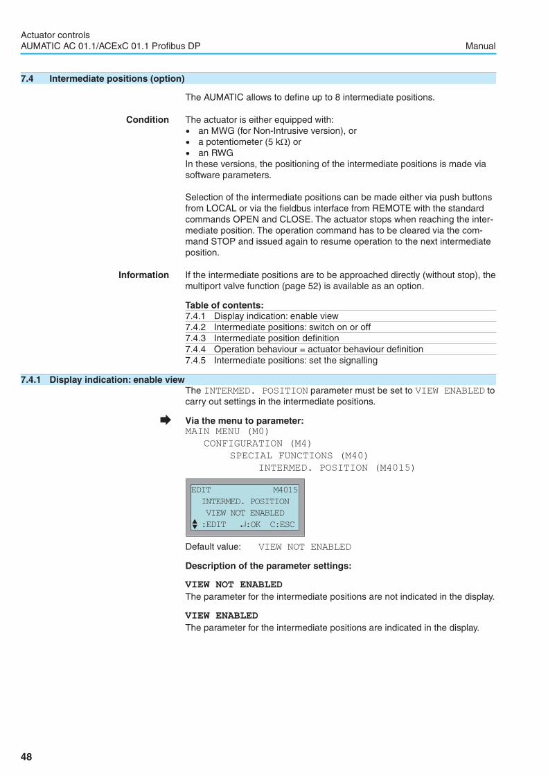
4.3.1 Display indication: enable viewThe EL. NAME PLATE setting must be set to VIEW ENABLED:
� Via the menu to parameter:MAIN MENU (M0)
CONFIGURATION (M4)
SPECIAL FUNCTIONS (M40)
EL. NAME PLATE (M4013)
Default value: VIEW ENABLED
� Description of the parameter settings:
VIEW NOT ENABLED
The electronic name plate is not shown in the display.
VIEW ENABLED
The electronic name plate is shown in the display.
4.3.2 Electronic name plate: view
� Via the menu to parameter:MAIN MENU (M0)
EL. NAME PLATE (M3)
ORDER DATA (M30)
PRODUCT DATA (M31)
PROJECT DATA (M32)
SERVICE DATA (M33)
17
Actuator controlsManual AUMATIC AC 01.1/ACExC 01.1 Profibus DP
EDIT M4013
EL. NAME PLATE
VIEW ENABLED
� :EDIT �:OK C:ESC
EL.NAME PLATE M30
ORDER DATA
PRODUCT DATA
PROJECT DATA

Project and user specific data are freely definable and can be entered bythe user:
Service information such as the AUMA service phone number and theAUMA Internet address can be indicated here:
18
Actuator controlsAUMATIC AC 01.1/ACExC 01.1 Profibus DP Manual
Service data (M33)SERVICE PHONE set in the factoryINTERNET ADDRESS www.auma.com, set in the factorySERVICE TEXT 1 can only be changed by service technicianSERVICE TEXT 2 can only be changed by service technician
Table 2
Project data (M32)PROJECT NAME adjustable (fields for customer input)CUSTOMER FIELD 1 adjustable (fields for customer input)CUSTOMER FIELD 2 adjustable (fields for customer input)
Table 3
Order data (M30)COMMISS NO.AUMATIC set in the factoryCOMMISS NO.ACTUATOR set in the factoryKKS NO. set in the factoryVALVE NO. adjustablePLANT NO. adjustable
Product data (M31)PRODUCT TYPE set in the factoryWORKS NO. ACTUATOR set in the factoryWORKS NO. AUMATIC set in the factoryLOGIC SFTWR. VER. software version of the logic, set in the factoryLOGIC HRDWR. VER. hardware version of the logic, set in the factoryDATE OF FINAL TEST set in the factoryWIRING DIAGRAM set in the factoryTERMINAL PLAN set in the factory
Table 4

4.4 Indication lights/LEDs
The indication lights/LEDs locally display the different operation states asoptical signals. The assignment of signals is freely selectable.
Table of contents:4.4.1 Standard indication4.4.2 Configuration of the signals: view/edit4.4.3 Blinking behaviour of indication lights/LEDs: view/edit
4.4.1 Standard indicationFigure 6 shows the indication lights/LEDs on the local controls:
Table 5 describes the standard indication.
Information The behaviour (blinking/illuminated) can be changed via the BLINKERparameter.
19
Actuator controlsManual AUMATIC AC 01.1/ACExC 01.1 Profibus DP
Figure 6
Version (standard): Version (option):LED marking with letters LED marking with figures
LED 1 (left)( symbol)
illuminated Actuator is in end position CLOSED
blinking Running indication: Actuator runs in directionCLOSE
LED 2 (T) illuminated Torque fault CLOSE
LED 3 (Th) illuminated Motor protection tripped
LED 4 (T) illuminated Torque fault OPEN
LED 5 (right)( symbol)
illuminated Actuator is in end position OPEN
blinking Running indication: Actuator runs in directionOPEN
LED 6 (BT)(option) illuminated Bluetooth connection available
Table 5

4.4.2 Configuration of the signals: view/edit
� Via the menu to parameter:MAIN MENU (M0)
SETTINGS (M1)
LOCAL CONTROLS (M13)
LED 1 (LEFT HAND) (M1312)
LED 2 (M1313)
LED 3 (M1314)
LED 4 (M1315)
LED 1 (RIGHT HAND) (M1316)
Default values: LED 1 (LEFT HAND) = CLOSING BLINK
LED 2 = TORQUE FAULT (CLOSE)
LED 3 = THERMO FAULT
LED 4 = TORQUE FAULT (OPEN)
LED 5 (RIGHT HAND)= OPENING BLINK
Information Table 10, page 27 describes the signals which can be assigned to the LEDs.Table 10 applies to both the LEDs and the output contacts.
20
Actuator controlsAUMATIC AC 01.1/ACExC 01.1 Profibus DP Manual
EDIT M1312
LED 1 (LEFT HAND)
CLOSING BLINK
� :EDIT �:OK C:ESC

4.4.3 Blinking behaviour of indication lights/LEDs: view/edit
� Via the menu to parameter:MAIN MENU (M0)
SETTINGS (M1)
LOCAL CONTROLS (M13)
BLINKER (M1311)
Default value: OFF IN MIDPOSITION
� Description of the parameter settings:
OFF
Blinker is switched off.
LIT IN MIDPOSITION
OFF IN MIDPOSITION
Information The BLINKER parameter also influences the blinking behaviour of outputcontacts 1 to 5 if they are used as a running indication.
21
Actuator controlsManual AUMATIC AC 01.1/ACExC 01.1 Profibus DP
LED 1 (yellow) illuminated Actuator is in end position CLOSED
blinking Actuator runs in direction CLOSE (runningindication)
LED 5 (green) illuminated Actuator is in end position OPEN
blinking Actuator runs in direction OPEN (running in-dication)
Table 6
LED 1 only (yellow) illuminated Actuator is in end position CLOSED
LED 1 (yellow) blinking Actuator runs in direction CLOSE (runningindication)
LED 5 only (green) illuminated Actuator is in end position OPEN
LED 5 (green) blinking Actuator runs in direction OPEN (running in-dication)
LED 1 (yellow) andLED 5 (green) illuminated Actuator is in an intermediate position
Table 7
EDIT M1311
BLINKER
OFF IN MIDPOSITION
� :EDIT �:OK C:ESC
5 Signals
5.1 Signals via fieldbus
Feedback signals via Profibus DP can be configured. Configuration is possi-ble for both data structure and data contents.Configuration is defined via the GSD file only. The selected configurationcan be indicated on the AUMATIC display.
Information It is possible to download the GSD file (General Station Description) fromthe Internet: www.auma.com
Table of contents:5.1.1 Configuration for process representation input: view5.1.2 Configuration of adjustable (user-definable) signals: view5.1.3 Configuration of fault signals: view5.1.4 Percent/per mil coding for transmission values: view
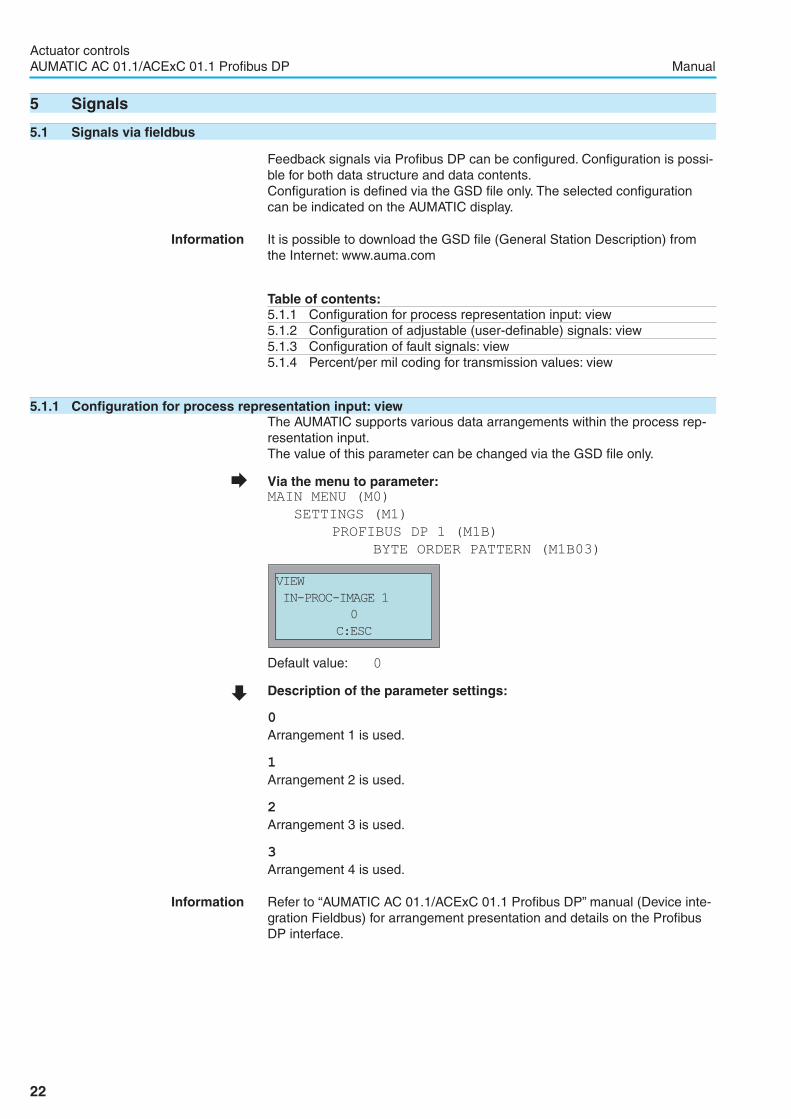
5.1.1 Configuration for process representation input: viewThe AUMATIC supports various data arrangements within the process rep-resentation input.The value of this parameter can be changed via the GSD file only.
� Via the menu to parameter:MAIN MENU (M0)
SETTINGS (M1)
PROFIBUS DP 1 (M1B)
BYTE ORDER PATTERN (M1B03)
Default value: 0
� Description of the parameter settings:
0
Arrangement 1 is used.
1
Arrangement 2 is used.
2
Arrangement 3 is used.
3
Arrangement 4 is used.
Information Refer to “AUMATIC AC 01.1/ACExC 01.1 Profibus DP” manual (Device inte-gration Fieldbus) for arrangement presentation and details on the ProfibusDP interface.
22
Actuator controlsAUMATIC AC 01.1/ACExC 01.1 Profibus DP Manual
VIEW
IN-PROC-IMAGE 1
0
C:ESC

5.1.2 Configuration of adjustable (user-definable) signals: viewWithin the process representation input, the users can configure the datacontents of 4 signal bytes out of a predefined signal set themselves.Configuration is defined via the GSD file only.
� Via the menu to parameter:MAIN MENU (M0)
SETTINGS (M1)
PROFIBUS DP 1 (M1B)
BYTE 5.0 CONFIG. (M1B04)to(M1B0A)BYTE 6.0 CONFIG. (M1B0D)to(M1B0K)BYTE 7.0 CONFIG. (M1B0L)to(M1B0S)BYTE 8.0 CONFIG. (M1B0T)to(M1B0a)
Example Byte 5.0:
Default values: Refer to “AUMATIC AC 01.1/ACExC 01.1 Profibus DP”manual (Fieldbus device integration), process representa-tion input.
� Description of the parameter settings:
23
Actuator controlsManual AUMATIC AC 01.1/ACExC 01.1 Profibus DP
Signals/indications on the display
Description
NOT USED No signals
CLOSED POSITIONSignals LSC (WSR) or LSC (WSR) and TSO(DOEL) (depending on type of seating)
OPEN POSITIONSignals LSO (WOEL) or LSO (WOEL) andTSO (DOEL) (depending to type of seating)
RUNNING CLOSE Actuator runs logically CLOSE
RUNNING OPEN Actuator runs logically OPEN
ACTUATOR MOVING
Actuator is running from LOCAL, REMOTE, orin manual operation. (Without positiontransmitter only the LOCAL or REMOTEoperation is indicated.)
LSC (WSR) Limit switch CLOSE operated
LSO (WOEL) Limit switch OPEN operated
TSC (DSR) Torque switch CLOSE operated
TSO (DOEL) Torque switch OPEN operated
THERMO FAULTMotor protection has tripped (reset may benecessary)
TORQUE FAULT (CLOSE) Torque fault in direction CLOSE occurred
TORQUE FAULT (OPEN) Torque fault in direction OPEN occurred
TORQUE FAULT (GEN.)Torque fault CLOSE or OPEN (combinedsignal)
SETPOINT E1 LOSSNominal value signal is by 0.3 mA lower thanthe lowest set value
FEEDBACK E2 LOSSActual position signal is by 0.3 mA lower thanthe lowest set value
SPEED E3 LOSS Not available
TORQUE E6 LOSSTorque signal is by 0.3 mA lower than thelowest set value
WARNING OPER.TIMEThe programmed max. operating time for anOPEN - CLOSE operation has been exceeded
WARNING STARTS/RUNThe max. number of starts/h or max. runningtime/h has been exceeded.
LOCAL SW. POSITION Selector switch in position LOCAL
REMOTE SW. POSITION Selector switch in position REMOTE
Table 8
VIEW
BYTE 5.0 CONFIG.
CLOSED POSITION
C:ESC

24
Actuator controlsAUMATIC AC 01.1/ACExC 01.1 Profibus DP Manual
Signals/indications on the display
Description
OFF SW. POSITION Selector switch in position OFF
REMOTE MODE Operation mode REMOTE active
SETPOINT MODE Operation mode SETPOINT MODE
INTERMED. POS. 1 Signalling of the intermediate positions 1 to 4.Signal behaviour according to POS.1CONTROL to POS.4 CONTROL parameters
INTERMED. POS. 2
INTERMED. POS. 3
INTERMED. POS. 4
STEPPING MODEProgrammed stepping range (START STEP
STOP STEP parameters) has been entered
CLOSING BLINK
Signal is blinking for operation in directionCLOSE. Signal is active in end positionCLOSED.
OPENING BLINKSignal is blinking for operation in directionOPEN. Signal is active in end position OPEN.
FAULT IND.
Collective signal includes: internal fault, torquefault, phase loss, thermal fault, andconfiguration fault (refer to status indications onpage 92)
WARNING IND.
Collective signal includes: operation timewarning, warning starts/run, no referenceoperation, internal warnings, and signal losses(refer to status indications on page 92)
NOT READY IND.
Collective signal includes: remote ready,selector switch not REMOTE, incorrectoperation command, emergency (refer to statusindications on page 93)
SETPOINT REACHED Actuator is in nominal position
LOSS OF PHASE One phase is missing
I/O ANALOG IN2 LOSSSignal loss of the parallel interface analogueinput 2
I/O ANALOG IN1 LOSSSignal loss of the parallel interface analogueinput 1
SELECTOR NOT REMOTE Selector switch not in position REMOTE
WRONG COMMAND
Wrong command received (several operationcommand bits set or setpoint > 100 % or >1000 ‰)
INTERNAL FAULTAn internal fault has occurred, see diagnosticindication D2
PE FAULT Not available
INTERNAL FEEDBACK
Actuator has not yet been opened to full endposition OPEN or closed to full end positionCLOSED
INTERNAL WARNINGAn internal warning has occurred, seediagnostic indication D3
CHANNEL 2 ACTIVECommunication is made via the redundantchannel
RUNNING LOCALThe actuator is operated by an operationcommand from the local controls
RUNNING REMOTEThe actuator is operated by an operationcommand from REMOTE
RUNNING WITH HANDWHLThe actuator is operated by turning thehandwheel
PROPOTIONAL RUNNING Not available
PHYS.DRIVE BREAK Actuator is in pause time of stepping mode
CLEAR STATEThe Profibus DP interface has received aGlobal Control CLEAR telegram
DIG.IN 1 BUS1 A +24 DC signal is present at the digital input(1 to 4) of the Profibus interface
DIG.IN 2 BUS1
DIG.IN 3 BUS1
DIG.IN 4 BUS1
INTERMED. POS. 5 Signalling of the intermediate positions 5 to 8.Signal behaviour according to POS.5CONTROL to POS.8 CONTROL parameters
INTERMED. POS. 6
INTERMED. POS. 7
INTERMED. POS. 8

5.1.3 Configuration of fault signals: viewFault signalling is made via byte 5.7.
� Via the menu to parameter:MAIN MENU (M0)
SETTINGS (M1)
PROFIBUS DP 1 (M1B)
BYTE 5.7 CONFIG. (M1B0B)
Default value: FAULT GROUP 3
� Description of the parameter settings:Table 9 indicates the values to be assigned for the alarm signals:
25
Actuator controlsManual AUMATIC AC 01.1/ACExC 01.1 Profibus DP
VIEW
BYTE 5.7 CONFIG.
FAULT GROUP 3
C:ESC
Value Signals (collective fault signal)
FAULT GROUP 1– FAULT IND.
– NOT READY IND.
FAULT GROUP 2– FAULT IND. without torque fault– NOT READY IND.
FAULT GROUP 3 – FAULT IND.
FAULT GROUP 4 – FAULT IND. without torque fault
FAULT GROUP 5
– FAULT IND.
– NOT READY IND.
– WARNING IND.
FAULT GROUP 6– FAULT IND. without thermal fault– NOT READY IND.
FAULT GROUP 7
– FAULT IND. without both torque and thermalfaults
– NOT READY IND.
FAULT GROUP 8 – FAULT IND. without thermal fault
FAULT GROUP 9– FAULT IND. without both torque and thermal
faults
FAULT GROUP 10
– FAULT without thermal fault– NOT READY IND.
– WARNING IND.
Table 9
Signals/indications on the display
Description
EMCY STOP BUTTONThe EMERGENCY - STOP button (option) hasbeen operated
FIBER OPTIC LOSS Fault at the fibre optic module (option)
BRAKE SUPPLY FAIL Not available
NOTIFY RESET Not available
DIG.IN 1 BUS2 Not available
DIG.IN 2 BUS2
DIG.IN 3 BUS2
DIG.IN 4 BUS2
RUNNING OPEN (LOCAL)
Actuator is running in direction OPEN (by anoperation command from the local controls orby turning the handwheel)
RUNNING CLOSE (LOCAL)
Actuator is running in direction CLOSE (by anoperation command from the local controls orby turning the handwheel)
INTERMED. POSITION Actuator in intermediate position

5.1.4 Percent/per mil coding for transmission values: viewThe coding of Profibus DP transmission values can be configured.
� Via the menu to parameter:MAIN MENU (M0)
SETTINGS (M1)
ANALOGUE VALUES DP (M1B0C)
Default value: 0– 100 PER CENT
Default value: 0-1000 PER MIL
� Description of the parameter settings:
0-100 PER CENT
Encoding of all analogue measured values is indicated in per cent.
0-1000 PER MIL
Encoding of all analogue measured values is indicated in per mil.
26
Actuator controlsAUMATIC AC 01.1/ACExC 01.1 Profibus DP Manual
EDIT
ANALOGUE VALUES DP
0-1000 PER MIL
C:ESC

5.2 Feedback via output contacts (binary) - (option)
These feedback signals are only available if a parallel interface is availablein addition to the fieldbus interface (refer to page 83).The output contacts can be used to indicate operation modes of the actuatoror the controls as binary signals. The assignment of signals is freelyselectable. Example:Output contact open = no thermal faultOutput closes = thermal fault in actuatorThe output contacts are described in the wiring diagram as follows:. Output contacts 1 to 5: DOUT1 through DOUT5. Alarm contacts: NC fault/NO ready
Table of contents:5.2.1 Configuration for output contacts 1 to 5: view/edit5.2.2 Configuration for alarm contacts (collective fault signal)5.2.3 Output contacts 1 to 5: use as a running indication (blinker)
5.2.1 Configuration for output contacts 1 to 5: view/edit
Information Fault signals can be issued via the ALARM CONTACT parameter, other sig-nals via the output contacts 1 to 5.
� Via the menu to parameter:MAIN MENU (M0)
SETTINGS (M1)
I/O 1 (M14)
OUTPUT CONTACT 1 (M1412)
OUTPUT CONTACT 2 (M1413)
OUTPUT CONTACT 3 (M1414)
OUTPUT CONTACT 4 (M1415)
OUTPUT CONTACT 5 (M1416)
Default values: OUTPUT CONTACT 1 = END POSITION OPEN
OUTPUT CONTACT 2 = END POSITION CLOSED
OUTPUT CONTACT 3 = SELECTOR SWITCH REMOTE
OUTPUT CONTACT 4 = TSC FAULTS
OUTPUT CONTACT 5 = TSO FAULTS
Table 10 shows the signal descriptions for the LEDs and the output contacts:
27
Actuator controlsManual AUMATIC AC 01.1/ACExC 01.1 Profibus DP
EDIT M1412
OUTPUT CONTACT 1
CLOSED POSITION
� :EDIT �:OK C:ESC
Signal DescriptionNOT USED No signals
CLOSED POSITIONSignals LSC (WSR) or LSC (WSR) and TSC(DSR) (depending on type of seating)
OPEN POSITIONSignals LSO (WOEL) or LSO (WOEL) andTSO (DOEL) (depending to type of seating)
RUNNING CLOSE Actuator runs logically CLOSERUNNING OPEN Actuator runs logically OPEN
ACTUATOR MOVING
Actuator is running from LOCAL, REMOTE, orin manual operation (without position transmit-ter, only LOCAL or REMOTE operation areindicated).
LSC (WSR) Limit switch CLOSE operatedLSO (WOEL) Limit switch OPEN operated
Table 10

28
Actuator controlsAUMATIC AC 01.1/ACExC 01.1 Profibus DP Manual
Signal DescriptionTSC (DSR) Torque switch CLOSE operatedTSO (DOEL) Torque switch OPEN operated
THERMO FAULTMotor protection has tripped (reset may be nec-essary)
TORQUE FAULT (CLOSE) Torque fault in direction CLOSE occurredTORQUE FAULT (OPEN) Torque fault in direction OPEN occurred
TORQUE FAULT (GEN.)Torque fault CLOSE or OPEN (combined sig-nal)
SETPOINT E1 LOSSNominal value signal is by 0.3 mA lower thanthe lowest set value
FEEDBACK E2 LOSSActual position signal is by 0.3 mA lower thanthe lowest set value
SPEED E3 LOSS not available
TORQUE E6 LOSSTorque signal is by 0.3 mA lower than the low-est set value
WARNING OPER.TIMEThe programmed max. operating time for anOPEN - CLOSE operation has been exceeded
WARNING STARTS/RUNThe max. number of starts/h or max. runningtime/h has been exceeded.
LOCAL SW. POSITION Selector switch in position LOCALREMOTE SW. POSITION Selector switch in position REMOTEOFF SW. POSITION Selector switch in position OFFREMOTE MODE Operation mode REMOTE activeSETPOINT MODE Operation mode SETPOINT MODEINTERMED. POS. 1
Signalisation of the intermediate positions 1 to4. Signal behaviour according to POS.1CONTROL to POS.4 CONTROL parameters
INTERMED. POS. 2
INTERMED. POS. 3
INTERMED. POS. 4
STEPPING MODEProgrammed stepping range (START STEP
STOP STEP parameters) has been entered
CLOSING BLINKSignal is blinking for operation in direction CLOSE.Signal is active in end position CLOSED.
OPENING BLINKSignal is blinking for operation in directionOPEN. Signal is active in end position OPEN.
FAULT IND.
Collective signal includes: internal fault, torquefault, phase loss, thermal fault, and internalfault (refer to status indications on page 92)
WARNING IND.
Collective signal includes: operation time warn-ing, warning starts/run, no reference operation,internal warnings, and signal losses (refer tostatus indications on page 92)
NOT READY IND.
Collective signal includes: remote ready selec-tor switch not REMOTE, incorrect operationcommand, emergency operation (refer to statusindications on page 93)
SETPOINT REACHED Actuator is in nominal positionLOSS OF PHASE One phase is missing
I/O1 ANALOG IN2 LOSSSignal loss of the parallel interface analogue in-put 2
I/O1 ANALOG IN1 LOSSSignal loss of the parallel interface analogue in-put 1
INTERMED. POS. 5
Signalisation of the intermediate positions 5 to8. Signal behaviour according to POS.5CONTROL to POS.8 CONTROL parameters
INTERMED. POS. 6
INTERMED. POS. 7
INTERMED. POS. 8
EMCY STOP BUTTONThe EMERGENCY - STOP button (option) hasbeen operated
FIBER OPTIC LOSS The FO loop module has detected a fibre breakINTERMED. POSITION Actuator in intermediate position
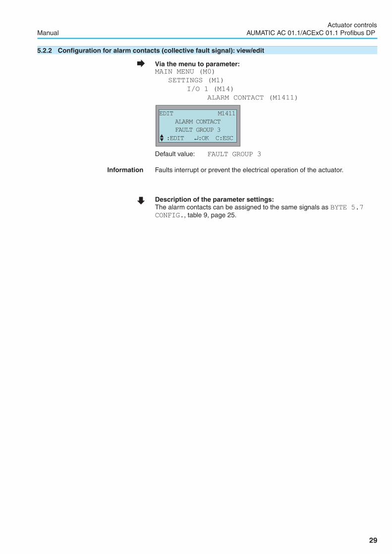
5.2.2 Configuration for alarm contacts (collective fault signal): view/edit
� Via the menu to parameter:MAIN MENU (M0)
SETTINGS (M1)
I/O 1 (M14)
ALARM CONTACT (M1411)
Default value: FAULT GROUP 3
Information Faults interrupt or prevent the electrical operation of the actuator.
� Description of the parameter settings:The alarm contacts can be assigned to the same signals as BYTE 5.7
CONFIG., table 9, page 25.
29
Actuator controlsManual AUMATIC AC 01.1/ACExC 01.1 Profibus DP
EDIT M1411
ALARM CONTACT
FAULT GROUP 3
� :EDIT �:OK C:ESC

5.2.3 Output contacts 1 to 5: use as running indication (blinker)
� Via the menu to parameter:MAIN MENU (M0)
SETTINGS (M1)
I/O 1 (M14)
OUTPUT CONTACT 1 (M1412)
OUTPUT CONTACT 2 (M1413)
OUTPUT CONTACT 3 (M1414)
OUTPUT CONTACT 4 (M1415)
OUTPUT CONTACT 5 (M1416)
� Description of the parameter settings:
CLOSING BLINK
Signal is active in end position CLOSED.Signal is blinking for operation in direction CLOSE (depending on theBLINKER parameter).
OPENING BLINK
Signal is active in end position OPEN.Signal is blinking for operation in direction OPEN (depending on theBLINKER parameter).
Information The output contacts/LEDs of the local controls (page 19) can also be usedto indicate whether the actuator is operated and if yes, in which direction.
Signal behaviour for BLINKER setting
� Via the menu to parameter:MAIN MENU (M0)
SETTINGS (M1)
LOCAL CONTROLS (M13)
BLINKER (M1311)
Default value: OFF IN MIDPOSITION
� Description of the parameter settings:
OFF
Signal is active in end position.Blinker (running indication) is switched off.
LIT IN MIDPOSITION
Signal is active in end position and blinking during operation in direction ofthe end position.The signal remains active in intermediate position.
Actuator controlsAUMATIC AC 01.1/ACExC 01.1 Profibus DP Manual
30
EDIT M1412
OUTPUT CONTACT 1
CLOSING BLINK
� :EDIT �:OK C:ESC
EDIT M1311
BLINKER
OFF IN MIDPOSITION
� :EDIT �:OK C:ESC

OFF IN MIDPOSITION
Signal is active in end position and blinking during operation in direction ofthe end position.The signal is off in intermediate position.
Information The BLINKER parameter also influences the blinking behaviour of the indi-cation lights/LEDs on the local controls.
5.3 Feedback signals (analogue) - (option)
These feedback signals are only available if a parallel interface is availablein addition to the fieldbus interface (refer to page 83).Depending on the actuator equipment, different signals can be recorded andissued as continuous values, e.g. 4 to 20 mA.
Table of contents:5.3.1 Position transmitter/actual position source (E2): view5.3.2 Source of the torque signal E6: view5.3.3 Feedback signals via analogue output 1: view5.3.4 Signal range at the analogue output 1: view/edit5.3.5 Feedback signals via analogue output 2: view5.3.6 Signal range at the analogue output 2: view/edit
5.3.1 Position transmitter/actual position source (E2): view
The valve position can be transmitted as a continuous signal by variousposition transmitters: The type of position transmitter/actual position source(E2) installed in the actuator is indicated here.This value is set in the factory and can only be changed by the AUMA ser-vice.
� Via the menu to parameter:MAIN MENU (M0)
CONFIGURATION (M4)
SETUP (M41)
FEEDBACK E2 (M4101)
Default value: POTENTIOMETER (for Non-Intrusive: MWG)
The following actual position sources (E2) are available:
� Description of the parameter settings:
NONE
There is no position transmitter available in the actuator.
POT.
There is a potentiometer installed in the actuator.
0 – 20mA
There is an RWG installed in the actuator. The position feedback signalamounts to 0 – 20 mA.
4 – 20mA
There is an RWG installed in the actuator. The position feedback signalamounts to 4 – 20 mA.
31
Actuator controlsManual AUMATIC AC 01.1/ACExC 01.1 Profibus DP
VIEW
FEEDBACK E2
POT.
C:ESC
MWG
There is an MWG (magnetic limit and torque transmitter) installed in theactuator.
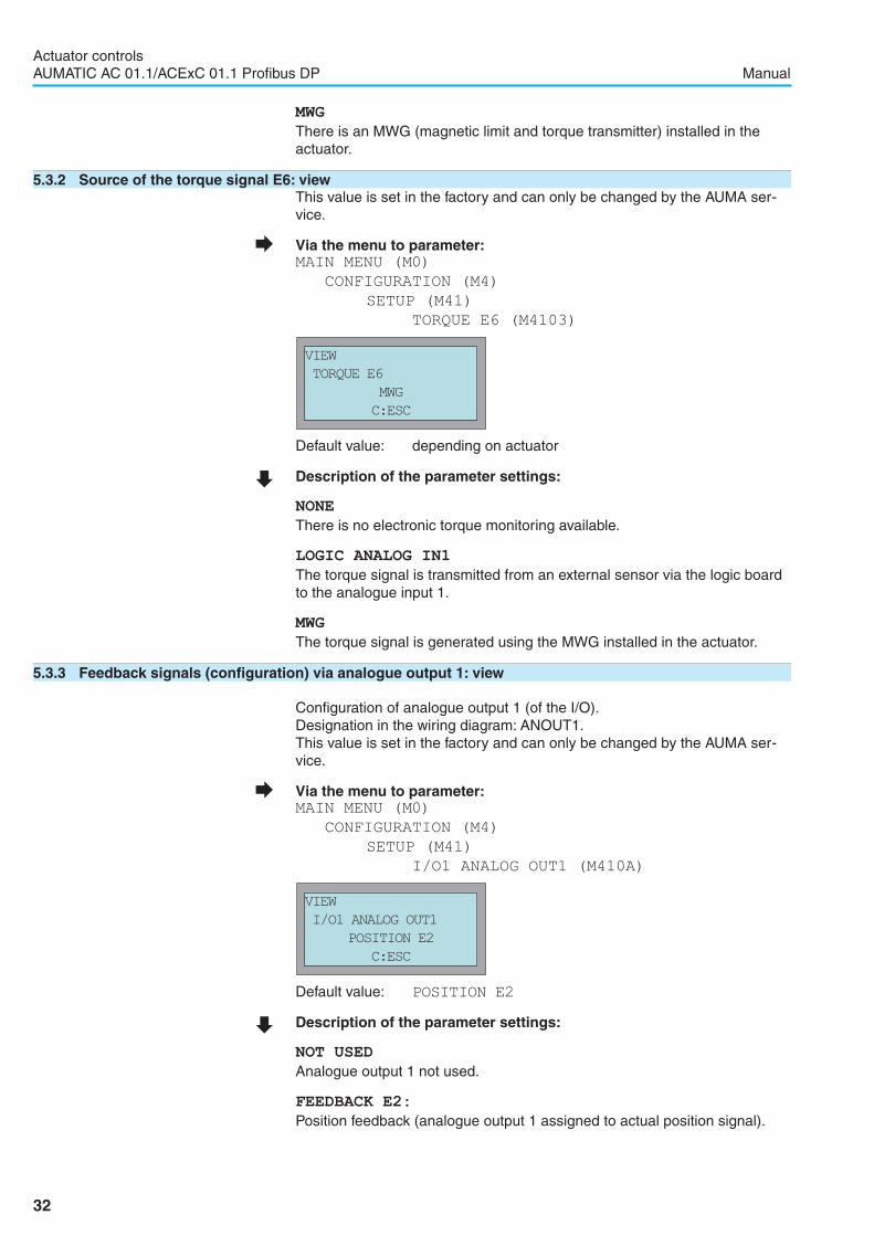
5.3.2 Source of the torque signal E6: viewThis value is set in the factory and can only be changed by the AUMA ser-vice.
� Via the menu to parameter:MAIN MENU (M0)
CONFIGURATION (M4)
SETUP (M41)
TORQUE E6 (M4103)
Default value: depending on actuator
� Description of the parameter settings:
NONE
There is no electronic torque monitoring available.
LOGIC ANALOG IN1
The torque signal is transmitted from an external sensor via the logic boardto the analogue input 1.
MWG
The torque signal is generated using the MWG installed in the actuator.
5.3.3 Feedback signals (configuration) via analogue output 1: view
Configuration of analogue output 1 (of the I/O).Designation in the wiring diagram: ANOUT1.This value is set in the factory and can only be changed by the AUMA ser-vice.
� Via the menu to parameter:MAIN MENU (M0)
CONFIGURATION (M4)
SETUP (M41)
I/O1 ANALOG OUT1 (M410A)
Default value: POSITION E2
� Description of the parameter settings:
NOT USED
Analogue output 1 not used.
FEEDBACK E2:
Position feedback (analogue output 1 assigned to actual position signal).
32
Actuator controlsAUMATIC AC 01.1/ACExC 01.1 Profibus DP Manual
VIEW
I/O1 ANALOG OUT1
POSITION E2
C:ESC
VIEW
TORQUE E6
MWG
C:ESC

If the actuator is equipped with a position transmitter (potentiometer, RWGor MWG), an analogue position feedback (galvanically isolated) is availableas a 0/4 – 20 mA signal at the electrical connection (see wiring diagram). Anadjustment to the end positions or the defined travel is not required. Anautomatic adjustment is done via the end positions (LSC (WSR) and LSO(WOEL)).For torque seating, the end positions OPEN and CLOSED of the limitswitching should be set as close as possible to the end positions of thevalve to minimise the deviation of the feedback.
TORQUE E6
Analogue torque feedback signal (analogue output 1 assigned to torque signal).If a magnetic limit and torque transmitter (MWG) is installed, an analoguetorque feedback (galvanically isolated) is available as a 0/4 – 20 mA signalat the electrical connection (refer to wiring diagram). The zero point is in thecentre of the selected output range (at 10 mA or 12 mA). The torque indirection CLOSE is indicated with 0 – 10 mA or 4 – 12 mA, the torque indirection OPEN with 10 – 20 mA or 12 – 20 mA. For 100 % of the nominaloutput torque, 0 or 4 mA is indicated in direction CLOSE, and 20 mA is indi-cated in direction OPEN.
5.3.4 Signal range at the analogue output 1: view/editSignal range at the analogue output 1 (of the I/O).This value must correspond to the desired feedback signal.
� Via the menu to parameter:MAIN MENU (M0)
CONFIGURATION (M4)
SETUP (M41)
I/O1 ANALOG OUT1 TYPE (M411B)
Default value: 0-20mA
� Description of the parameter settings:0-20mA
Analogue output 1 generates a 0 – 20 mA signal.
4-20mA
Analogue output 1 generates a 4 – 20 mA signal.
20-0mA
Analogue output 1 generates a 20 – 0 mA signal.
20-4mA
Analogue output 1 generates a 20 – 4 mA signal.
33
Actuator controlsManual AUMATIC AC 01.1/ACExC 01.1 Profibus DP
0 mA(4 mA)
– 100 %
10 mA(12 mA)
0 %
20 mA(20 mA)
+ 100 %
Figure 7
–100%= max. nominal torque reachedinendpositionCLOSED
+ 100 % = max. nominal torque reachedin end position OPEN
EDIT M411B
I/O1 ANALOG OUT1 TYP
0-20mA
� :EDIT �:OK C:ESC

5.3.5 Feedback signals (configuration) via analogue output 2: viewConfiguration of analogue output 2 (of the I/O).Designation in the wiring diagram: ANOUT2.This value is set in the factory and can only be changed by the AUMAservice.
� Via the menu to parameter:MAIN MENU (M0)
CONFIGURATION (M4)
SETUP (M41)
I/O1 ANALOG OUT2 (M410C)
Default value: TORQUE E6
� Description of the parameter settings:
NOT USED
Analogue output 2 not used.
FEEDBACK E2:
Position feedback (analogue output 2 assigned to actual position signal).Description see analogue output 1.
TORQUE E6
Analogue torque feedback signal (analogue output 2 assigned to torque sig-nal). Description see analogue output 1.
5.3.6 Signal range at the analogue output 2: view/editSignal range at the analogue output 2 (of the I/O).This value must correspond to the desired feedback signal.
� Via the menu to parameter:MAIN MENU (M0)
CONFIGURATION (M4)
SETUP (M41)
I/O1 ANALOG OUT2 TYPE (M411D)
Default value: 0-20mA
� Description of the parameter settings:
0-20mA
Analogue output 2 generates a 0 – 20 mA signal.
4-20mA
Analogue output 2 generates a 4 – 20 mA signal.
20-0mA
Analogue output 2 generates a 20 – 0 mA signal.
20-4mA
Analogue output 2 generates a 20 – 4 mA signal.
34
Actuator controlsAUMATIC AC 01.1/ACExC 01.1 Profibus DP Manual
VIEW
I/O1 ANALOG OUT2
TORQUE E6
C:ESC
EDIT M411D
I/O1 ANALOG OUT1 TYPE
0-20 mA
� :EDIT �:OK C:ESC

6 Operation mode
Different operation modes (operation types) are available:The current operation mode is indicated in the first line of the display:
Table of contents and short description of the operation modes (opera-tion types):6.1 Operation mode OFF
No local or remote control possible.6.2 Operation mode LOCAL
Control via push buttons OPEN, STOP, CLOSE at the local controls.6.3 Operation mode REMOTE MODE
Control via commands OPEN, STOP, CLOSE from remote controlroom or process control system.
6.4 Operation mode EMERGENCYControl via command EMERGENCY from control room or processcontrol system.
6.5 Operation mode FAILUREActuator behaviour on loss of signal.
Further information in other clauses:7.6 Positioner (operation mode SETPOINT MODE)
Control via analogue set point, e.g. of 0 – 20 mA7.9 Operation mode RESTRICTED
Operation via the local controls of the AUMATIC is disabled.7.10 Operation mode EMERGENCY STOP
In combination with the EMERGENCY STOP button.
6.1 Operation mode OFF
� Set selector switch to position 0 (OFF).
Display indicates:
. No local control possible.. No remote control possible.. No EMERGENCY operation possible.. The controls remain fully operative as far as signalling is concerned (thecontrols’ power supply is maintained).. The�,�, � , C push buttons can be used to set parameters andindications via the display.
35
Actuator controlsManual AUMATIC AC 01.1/ACExC 01.1 Profibus DP
� OFF S0
�LOCAL MODE S0
OPEN
E2 100 %
RUNNING OPEN
0
II

6.2 Operation mode LOCAL
� Set selector switch to position Local control (LOCAL).
Display indicates:
. The actuator can be controlled via OPEN - STOP - CLOSE push buttonsof the local controls.. Faults and warnings without automatic reset can be confirmed with theReset push button.
6.2.1 Push-to-run operation or self-retaining: set for operation mode LOCAL
� Via the menu to parameter:MAIN MENU (M0)
SETTINGS (M1)LOCAL CONTROLS (M13)
MAINTAINED LOCAL (M1310)
Default value: OPEN + CLOSE (STOP)
� Description of the parameter settings:
OFF
Push-to-run operation on, self-retaining off:Actuator runs in direction OPEN or CLOSE, depending on the operationcommand issued. If the operation command is removed, the actuator stops.OPEN
In direction OPEN = self-retaining (direction CLOSE push-to-run operation):After an operation command in direction OPEN, the actuators continueseven if the operation command is removed (self-retaining). The actuator isstopped via the STOP command or once the end position OPEN is reached.CLOSE
In direction CLOSE = self-retaining (direction OPEN push-to-run operation):After an operation command in direction CLOSE, the actuators continues evenif the operation command is removed (self-retaining). The actuator is stoppedvia the STOP command or once the end position CLOSED is reached.OPEN + CLOSE (STOP)
In direction OPEN and CLOSE = self-retaining:After an operation command the actuator continues in direction OPEN orCLOSE, even if the operation command is removed (self-retaining). Theactuator is stopped via the STOP command in an the end position.OPEN+CLOSE (NO STOP)
In direction OPEN and CLOSE = self-retaining without STOPA direct reversal of the direction of without STOP command is possible.
36
Actuator controlsAUMATIC AC 01.1/ACExC 01.1 Profibus DP Manual
�� LOCAL MODE S0
EDIT M1310MAINTAINED LOCAL
OPEN + CLOSE (STOP)�� :EDIT ↵:OK C:ESC
0
II

6.3 Operation mode REMOTE
� Set selector switch to position Remote control (REMOTE).
Display indicates:
The actuator is controlled by external REMOTE commands OPEN - STOP -CLOSE.
Information If SETPOINT MODE is displayed, a positioner (option) is available. In thiscase, selection can be made between REMOTE MODE and SETPOINTMODE (refer to page 58).
6.3.1 Push-to-run operation or self-retaining: set for operation mode REMOTEThe parameter has no influence on the operation commands transmitted viafieldbus.Setting is only required if a further parallel interface is available in addition tothe fieldbus interface (refer to page 83).
� Via the menu to parameter:MAIN MENU (M0)
SETTINGS (M1)
I/O 1 (M14)
MAINTAINED REMOTE (M1410)
Default value: OFF
� Description of the parameter settings:
OFF
Push-to-run operation off, self-retaining activated:Actuator runs in direction OPEN or CLOSE after an operation command hasbeen issued. If the operation command is removed, the actuator continuesto run (self-retaining) until it is stopped by the command STOP or an endposition or intermediate position has been reached.
OPEN
Push-to-run operation in direction OPEN activated:Actuator only runs in direction OPEN while an operation command isissued. If the operation command is removed, the actuator stops.
CLOSE
Push-to-run operation in direction CLOSE activated:Actuator only runs in direction CLOSE while an operation command isissued. If the operation command is removed, the actuator stops.
37
Actuator controlsManual AUMATIC AC 01.1/ACExC 01.1 Profibus DP
� REMOTE MODE S0
0
II
EDIT M1410
MAINTAINED REMOTE
OFF
� :EDIT �:OK C:ESC
OPEN + CLOSE (STOP)
Push-to-run operation in direction OPEN and CLOSE activated:Actuator only runs in direction OPEN or CLOSE while an operation com-mand is issued. If the operation command is removed, the actuator stops.
OPEN+CLOSE (NO STOP)
Self-retaining without STOP:A direct reversal of the direction of rotation without STOP command is pos-sible.
6.4 Operation mode EMERGENCY
In an emergency, the actuator can be brought to a programmed EMER-GENCY position by removing the EMERGENCY signal.As the EMERGENCY signal works active low, 24 V DC must be present atthe EMERGENCY input while in the normal state (refer to wiring diagram).An EMERGENCY operation is performed when the signal is interrupted (0 V).During EMERGENCY operation the actuator does not perform any operationcommands.After initiating an EMERGENCY operation (the EMERGENCY input is againsupplied with 24 V DC), the operation commands must be deleted and haveto be reapplied. This does not apply to operation commands being trans-ferred via the 0/4 – 20 mA input or via fieldbus telegrams. They will immedi-ately be executed again.
Information For actuators equipped with a fieldbus interface, the EMERGENCY opera-tion behaviour is only available if an I/O interface (fieldbus standard combi-nation, page 83) or additional control inputs (80) are available.
Table of contents:6.4.1 Operation mode (type of duty) activation for an EMERGENCY operation6.4.2 EMERGENCY operation: switch on or off/signal behaviour definition6.4.3 Actuator behaviour definition in case of an EMERGENCY operation6.4.4 EMERGENCY position definition6.4.5 Motor protection and/or torque switching: by-pass
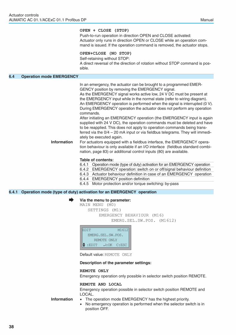
6.4.1 Operation mode (type of duty) activation for an EMERGENCY operation
� Via the menu to parameter:MAIN MENU (M0)
SETTINGS (M1)
EMERGENCY BEHAVIOUR (M16)
EMERG.SEL.SW.POS. (M1612)
Default value:REMOTE ONLY
Description of the parameter settings:
REMOTE ONLY
Emergency operation only possible in selector switch position REMOTE.
REMOTE AND LOCAL
Emergency operation possible in selector switch position REMOTE andLOCAL.
Information . The operation mode EMERGENCY has the highest priority.. No emergency operation is performed when the selector switch is inposition OFF.
38
Actuator controlsAUMATIC AC 01.1/ACExC 01.1 Profibus DP Manual
EDIT M1612
EMERG.SEL.SW.POS.
REMOTE ONLY
� :EDIT �:OK C:ESC

6.4.2 EMERGENCY operation: switch on or off/signal behaviour definition
� Via the menu to parameter:MAIN MENU (M0)
SETTINGS (M1)
EMERGENCY BEHAVIOUR (M16)
EMERGENCY BEHAVIOUR (M1610)
Default value:OFF
� Description of the parameter settings:
OFF
Emergency operation is switched off.
GOOD SIGNAL FIRST
An EMERGENCY operation is only triggered when the EMERGENCY signalat the EMERGENCY input drops from 24 V to 0 V, i.e. provided that a 24 Vsignal was previously connected to the EMERGENCY input.
ACTIVE IMMEDIATE
An EMERGENCY operation is only initiated if 0 V are connected to theEMERGENCY signal input.
Information For ACTIVE IMMEDIATE, an EMERGENCY operation is initiated immedi-ately after the actuator is switched on, when 0 V are connected to theEMERGENCY signal input.
6.4.3 Actuator behaviour definition in case of an EMERGENCY operation
� Via the menu to parameter:MAIN MENU (M0)
SETTINGS (M1)
EMERGENCY BEHAVIOUR (M16)
EMERGENCY POSITION (M1611)
Default value: FAIL AS IS
� Description of the parameter settings:
FAIL AS IS
The actuator stops in the current position.
FAIL CLOSE
The actuator runs to end position CLOSED.
FAIL OPEN
The actuator runs to end position OPEN.
FAIL TO PRESET
The actuator runs to the predetermined position.
39
Actuator controlsManual AUMATIC AC 01.1/ACExC 01.1 Profibus DP
EDIT M1610
EMERGENCY BEHAVIOUR
OFF
� :EDIT �:OK C:ESC
EDIT M1611
EMERGENCY POSITION
FAIL AS IS
� :EDIT �:OK C:ESC

6.4.4 EMERGENCY position definitionIf the EMERGENCY operation action FAIL TO PRESET (EMERGENCYPOSITION parameter) is set, the actuator runs to the EMERGENCYposition stated here.
� Via the menu to parameter:MAIN MENU (M0)
SETTINGS (M1)
EMERGENCY BEHAVIOUR (M16)
PRESET POSITION (M1614)
Default value: 0,0 %
Setting range: from 0.0 % to 100.0 % (from OPEN to CLOSED)
6.4.5 Motor protection and/or torque switching: by-passDuring the EMERGENCY operation, the motor protection and/or torqueswitching can be by-passed.This value is set in the factory and can only be changed by authorisedAUMA staff.
� Via the menu to parameter:MAIN MENU (M0)
SETTINGS (M1)
EMERGENCY BEHAVIOUR (M16)
EMERGENCY BY-PASS (M1603)
Default value: NONE
� Description of the parameter settings:
NONE
No by-pass of motor protection.
THERMAL
The signals of the thermoswitches or the PTC thermistors of the motorwinding are by-passed.
TORQUE
The signals of the torque switching in the actuator (TSC (DSR)/TSO(DOEL)) are by-passed
THERMAL AND TORQUE
The signals of the thermoswitches or PTC thermistors and the signals of thetorque switching are by-passed.
Information For actuators with explosion protection, the motor protection and the torqueswitching cannot be by-passed.
40
Actuator controlsAUMATIC AC 01.1/ACExC 01.1 Profibus DP Manual
EDIT M1614
PRESET POSITION
0.0%
� :EDIT �:OK C:ESC
EDIT M1603
EMERGENCY BY-PASS
NONE
C:ESC

6.5 Operation mode FAILURE
The operation mode FAILURE enables an initiation of failure operations incase of signal loss or loss of bus communication.
If the FAILURE mode is enabled, the display indicates:
Table of contents:6.5.1 Failure behaviour: switch on or off6.5.2 Source for initiation (failure source): set for the failure operation.6.5.3 Actuator reaction (failure position): set on loss of signal6.5.4 Preset position definition6.5.5 Failure delay time setting6.5.6 Failure behaviour for bus communication loss
6.5.1 Failure behaviour: switch on or off
� Via the menu to parameter:MAIN MENU (M0)
SETTINGS (M1)
FAILURE BEHAVIOUR (M15)
FAILURE BEHAVIOUR (M1510)
Default value: OFF
Description of the parameter settings:
OFF
Failure behaviour is switched off.
GOOD SIGNAL FIRST
A failure operation is only initiated if no cable break is recognised afterswitching on, but loss of signal is recognised later through cable break.With this setting, it is ensured that the actuator does not perform a presetfailure action (failure position) when switched on without signal E1 con-nected.
FAIL IMMEDIATE
A failure operation is initiated in case of cable break.
Information If FAIL IMMEDIATE is switched on, a failure operation is initiated immedi-ately after the actuator is switched on if a cable break has occurred.
41
Actuator controlsManual AUMATIC AC 01.1/ACExC 01.1 Profibus DP
� FAILURE MODE S0
EDIT M1510
FAILURE BEHAVIOUR
OFF
� :EDIT �:OK C:ESC

6.5.2 Source for initiation (failure source): set for failure operation
� Via the menu to parameter:MAIN MENU (M0)
SETTINGS (M1)
FAILURE BEHAVIOUR (M15)
FAILURE SOURCE (M1514)
Default value: E1 OR E2 FEEDBACK
� Description of the parameter settings:
SETPOINT E1
Failure behaviour is initiated if setpoint E1 or actual value E2 fail or in caseof loss of the bus communication.The monitoring depends on the preset setpoint range, e.g.:E1 = 4 – 20 mA, E1 lower than 3.7 mA = loss of signalE1 = 10 – 20 mA, E1 lower than 9.7 mA = loss of signalMonitoring of E1 = 0 – 20 mA is not possible
E1 OR E2 FEEDBACK
Failure behaviour is initiated if setpoint E1 or feedback E2 fail.The following is monitored:. for actuators with potentiometer: Cable break is detected. for electronic position transmitter RWG 4 – 20 mA in actuator:
E2 lower than 3.7 mA = signal loss. for MWG in actuator:Communication faults and MWG internal faults are recognised
E1, E2 OR E4 FEEDBACK
Failure behaviour is initiated if setpoint E1, feedback E2, or actual processvariable E4 fail
BUS INTERFACE
A failure behaviour is initiated in case of loss of bus communication
6.5.3 Actuator reaction (failure position): set on loss of signal
� Via the menu to parameter:MAIN MENU (M0)
SETTINGS (M1)
FAILURE BEHAVIOUR (M15)
FAILURE POSITION (M1512)
Default value: FAIL AS IS
Description of the parameter settings:
FAIL AS IS
The actuator stops in the current position.
42
Actuator controlsAUMATIC AC 01.1/ACExC 01.1 Profibus DP Manual
EDIT M1512
FAILURE POSITION
FAIL AS IS
� :EDIT �:OK C:ESC
EDIT M1514
FAILURE SOURCE
E1 OR E2 FEEDBACK
� :EDIT �:OK C:ESC

FAIL CLOSE
The actuator runs to end position CLOSED.
FAIL OPEN
The actuator runs to end position OPEN.
FAIL TO PRESET
The actuator runs to the predetermined position.
6.5.4 Preset position definitionIf the FAILURE TO PRESET failure action(FAILURE POSITION param-eter) is set, the actuator runs to the preset position stated here.
� Via the menu to parameter:MAIN MENU (M0)
SETTINGS (M1)
FAILURE BEHAVIOUR (M15)
PRESET POSITION (M1513)
Default value: 0.0 %
Setting range: from 0.0 % to 100.0 % (from OPEN to CLOSED)
6.5.5 Failure delay time settingDetermines the time elapsed between the recognition of a cable break andthe initiation of the failure action.
� Via the menu to parameter:MAIN MENU (M0)
SETTINGS (M1)
FAILURE BEHAVIOUR (M15)
DELAY TIME (M1511)
Default value: 3.0 sSetting range: 0.0 to 1200.0 seconds (20 min.)
43
Actuator controlsManual AUMATIC AC 01.1/ACExC 01.1 Profibus DP
EDIT M1513
PRESET POSITION
0.0 %
� :EDIT �:OK C:ESC
EDIT M1511
DELAY TIME
3.0 s
� :EDIT �:OK C:ESC

6.5.6 Failure behaviour on bus communication loss
A failure operation can be initiated in case of bus communication loss.Preliminary conditions:. The failure behaviour is activated (FAILURE BEHAVIOUR M1510
parameter is switched on).. The reason for initiation (FAILURE SOURCE M1514 parameter) is setto BUSINTERFACE.
Sources for initiation (failure sources) for failure operation are:. The connection to the master is interrupted.. The master goes into clear status and sends:– either the Global Control Telegram with Clear contents.– or data telegrams of length 0 (DP FailSafe Mode).
A failure operation on bus communication loss can only be initiated if thewatchdog function in the master is activated.
If the reason for initiation of the failure function has been eliminated (con-nection reestablished, master in operate status), the master can resume theexecution of operation commands.
44
Actuator controlsAUMATIC AC 01.1/ACExC 01.1 Profibus DP Manual
NOTICE

7 Functions
7.1 Type of seating: check/edit end positions
Limit seating The limit switching is set in such a way that the actuator switches off at thedesired switching points. The torque switching acts as an overload protec-tion for the valve.
Torque seating The torque switching is set to the desired tripping torque. After reaching thetripping torque the actuator is turned off.The limit seating needs to be set in such a way that the limit switching is trip-ped shortly before reaching the set tripping torque. If this is not the case,one of the following fault signals is displayed: TSO FAULTS or TSCFAULTS (menu S1).
� Via the menu to parameter:MAIN MENU (M0)
SETTINGS (M1)
SEATING MODE (M11)
OPEN POSITION (M1110)
CLOSED POSITION (M1111)
Default value: LIMIT
45
Actuator controlsManual AUMATIC AC 01.1/ACExC 01.1 Profibus DP
Valve damage due to incorrect setting!� The type of seating must suit the valve.� Only change the setting with the consent of the valve manufacturer.
EDIT M1111
CLOSED POSITION
LIMIT
� :EDIT �:OK C:ESC
EDIT M1110
OPEN POSITION
LIMIT
� :EDIT �:OK C:ESC
NOTICE

7.2 Torque switching: check/set
This setting is only possible for the non-intrusive version.For further information refer to page 8.
� Via the menu to parameter:MAIN MENU (M0)
SETTINGS (M1)
TORQUE (M12)
OPENING (M1210)
CLOSING (M1211)
Default value: according to order dataSetting range: according to torque setting range
refer to actuator name plate
Information The value can be displayed in percent, Newtonmeter (Nm) or in Lbs/ft.To change the display unit, refer to page 16.For display in percent:100 % corresponds to the max. torque indicated on the name plate of theactuator.Example: SA 07.5 with 20 – 60 Nm: 100 % = 60 Nm
33 % = 20 Nm
Information The following fault signals are sent if torque setting has been reached inmid-travel:. Status indication S0: operation mode LOCAL/OFF = FLT + NR. Status indication S0/S6: operation mode REMOTE = FAULT IND.. Status indication S1: TORQUE FAULT (OPEN) or TORQUE FAULT
(CLOSE)(torque fault)The fault has to be acknowledged before the operation can be resumed.Acknowledgement can be made:1. by an operation command in the opposite direction.
– For TORQUE FAULT (CLOSE): Operation command in directionOPEN
– For TORQUE FAULT (OPEN): Operation command in directionCLOSE
2. or in case the torque present is smaller than the preset tripping torque:– via the Reset push button in selector switch position LOCAL– or the Profibus, reset command (process representation output:
byte 1, bit 3)
46
Actuator controlsAUMATIC AC 01.1/ACExC 01.1 Profibus DP Manual
Valve damage due to incorrect setting!� The torque must suit the valve.� Only change the setting with the consent of the valve manufacturer.
EDIT M1211
CLOSING
100%
� :EDIT �:OK C:ESC
EDIT M1210
OPENING
100%
� :EDIT �:OK C:ESC
NOTICE

7.3 Limit switching setting
This setting is only possible for the non-intrusive versionFor further information refer to page 8.
� Via the menu to parameter:MAIN MENU (M0)
SETTINGS (M1)
SET LIMIT SWITCHES (M10)
CLOSED POSITION (M100)
OPEN POSITION (M101)
Information For end position setting, turn selector switch to LOCAL position and movethe actuator into the end position, either via manual or motor operation(using the push buttons). Then turn the selector switch back to position OFFand accept end position.
Information If an end position cannot be set:� Check the type of control unit in actuator.
47
Actuator controlsManual AUMATIC AC 01.1/ACExC 01.1 Profibus DP
Valve damage due to direct approaching of mechanical end stop dur-ing motor operation!� During motor operation, interrupt travel before reaching the mechanical
valve/gearbox end stop (press push button STOP ).
SET LIMIT SWITC M100
CLOSED POSITION
63.3 %
�:EDIT C:ESC
SET LIMIT SWITC M101
�OPEN POSITION
63.3 %
�:EDIT C:ESC
NOTICE
7.4 Intermediate positions (option)
The AUMATIC allows to define up to 8 intermediate positions.
Condition The actuator is either equipped with:. an MWG (for Non-Intrusive version), or. a potentiometer (5 k�) or. an RWGIn these versions, the positioning of the intermediate positions is made viasoftware parameters.
Selection of the intermediate positions can be made either via push buttonsfrom LOCAL or via the fieldbus interface from REMOTE with the standardcommands OPEN and CLOSE. The actuator stops when reaching the inter-mediate position. The operation command has to be cleared via the com-mand STOP and issued again to resume operation to the next intermediateposition.
Information If the intermediate positions are to be approached directly (without stop), themultiport valve function (page 52) is available as an option.
Table of contents:7.4.1 Display indication: enable view7.4.2 Intermediate positions: switch on or off7.4.3 Intermediate position definition7.4.4 Operation behaviour = actuator behaviour definition7.4.5 Intermediate positions: set the signalling
7.4.1 Display indication: enable viewThe INTERMED. POSITION parameter must be set to VIEW ENABLED tocarry out settings in the intermediate positions.
� Via the menu to parameter:MAIN MENU (M0)
CONFIGURATION (M4)
SPECIAL FUNCTIONS (M40)
INTERMED. POSITION (M4015)
Default value: VIEW NOT ENABLED
Description of the parameter settings:
VIEW NOT ENABLED
The parameter for the intermediate positions are not indicated in the display.
VIEW ENABLED
The parameter for the intermediate positions are indicated in the display.
48
Actuator controlsAUMATIC AC 01.1/ACExC 01.1 Profibus DP Manual
EDIT M4015
INTERMED. POSITION
VIEW NOT ENABLED
� :EDIT �:OK C:ESC

7.4.2 Intermediate positions: switch on or offEach intermediate position (POS.1 to POS.8.) may individually beswitched on/off.
� Via the menu to parameter:MAIN MENU (M0)
SETTINGS (M1)
INTERMED. POSITION (M1C)
POS.1 SELECTOR SW. (M1C12)
Default value: OFF
� Description of the parameter settings:
OFF
Intermediate position switched off.
REMOTE ONLY
Intermediate position only active in operation mode REMOTE.
LOCAL ONLY
Intermediate position only active in operation mode LOCAL.
REMOTE AND LOCAL
Intermediate position active in operation modes REMOTE and LOCAL.
7.4.3 Intermediate position definitionEach intermediate position (POS.1 to POS.8) can be set to any valuebetween 0 % and 100 % of the travel.This function is only available for the Non-intrusive version
� Via the menu to parameter:MAIN MENU (M0)
SETTINGS (M1)
INTERMED. POSITION (M1C)
POS.1 (M1C10)
Default value: 0,0 %
Setting range: 0.0 % to 100.0 % of the travel(from OPEN to CLOSED)
49
Actuator controlsManual AUMATIC AC 01.1/ACExC 01.1 Profibus DP
EDIT M1C12
POS.1 SELECTOR SW
OFF
� :EDIT �:OK C:ESC
EDIT M1C10
POS.1
0.0 %
� :EDIT �:OK C:ESC

7.4.4 Operation behaviour = actuator behaviour definitionThe reaction of the actuator upon reaching an intermediate position can beprogrammed via the parameters “POS. 1: BEHAVIOUR to POS. 8:
BEHAVIOUR.
� Via the menu to parameter:MAIN MENU (M0)
SETTINGS (M1)
INTERMED. POSITION (M1C)
POS.1 BEHAVIOUR (M1C11)
Default value: NO STOP
� Description of the parameter settings:
NO STOP
No intermediate stop, actuator continues the operation.
STOP OPENING DIR.
Actuator stops during operation in direction OPEN upon having reached theintermediate position. Actuator only runs after a new operation command isissued.This function is not active in the operation mode SETPOINT MODE.
STOP CLOSING DIR.
Actuator stops during operation in direction CLOSE after reaching the inter-mediate position. Actuator only runs after a new operation command isissued.This function is not active in the operation mode SETPOINT MODE.
STOP BOTH DIR.
Actuator stops after reaching the intermediate position. Actuator only runsafter a new operation command is issued.This function is not active in the operation mode SETPOINT MODE.
7.4.5 Intermediate positions: set the signallingThe reaching of an intermediate position can be signalled:. via bus (see separate operation instructions). via the indication lights (LEDs) of the local controls (page 19) or. via the output contacts (page 27)
The signal behaviour of the individual intermediate positions is set via thePOS.1-8 control parameters:
� Via the menu to parameter:MAIN MENU (M0)
SETTINGS (M1)
INTERMED. POSITION (M1C)
POS.1 CONTROL (M1C13)
Default value: NOT USED
50
Actuator controlsAUMATIC AC 01.1/ACExC 01.1 Profibus DP Manual
EDIT M1C11
POS.1 BEHAVIOUR
NO STOP
� :EDIT �:OK C:ESC
EDIT M1C13
POS.1 CONTROL
NOT USED
� :EDIT �:OK C:ESC

� Description of the parameter settings:
NOT USED
No signal.
C_ _ _ POS¯¯¯¯¯O
Signal active from reaching the intermediate position to end position OPEN.
C¯¯¯¯¯POS_ _ _ O
Signal active from end position CLOSED to reaching the intermediate posi-tion.
C_ _ _ POS_ _ _ O
Impulse signal issued when going through intermediate position
Figure 8 shows the signal behaviour in intermediate positions.
Further feedback signals which can be used together with the multiportvalve function (option):
Description of the parameter settings:
SETPOINT REACHED
As each intermediate position is processed as a setpoint, the signalSETPOINT REACHED is issued after reaching any intermediate position.
ACTUATOR MOVING
Is signalled as long as the actuator is still running to the intermediate posi-tion and no intermediate position signal has been issued yet.
51
Actuator controlsManual AUMATIC AC 01.1/ACExC 01.1 Profibus DP
0
1
0
1
0
1
0
1
POS
A
B
C
D
Figure 8
A NOT USED 1 Active signalB C_ _ _ POS¯¯¯¯¯¯O 2 Signal not activatedC C¯¯¯¯¯¯POS_ _ _ OD C_ _ _ POS_ _ _ O POS = intermediate position
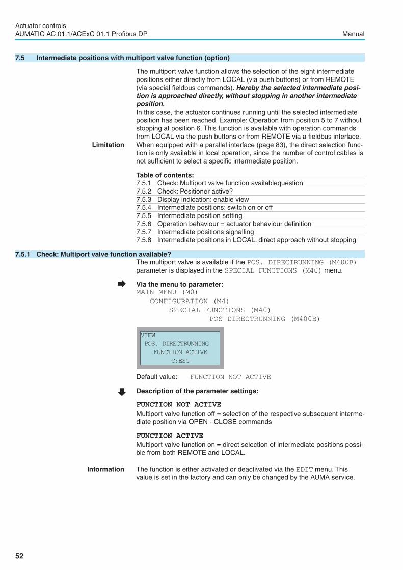
7.5 Intermediate positions with multiport valve function (option)
The multiport valve function allows the selection of the eight intermediatepositions either directly from LOCAL (via push buttons) or from REMOTE(via special fieldbus commands). Hereby the selected intermediate posi-tion is approached directly, without stopping in another intermediateposition.In this case, the actuator continues running until the selected intermediateposition has been reached. Example: Operation from position 5 to 7 withoutstopping at position 6. This function is available with operation commandsfrom LOCAL via the push buttons or from REMOTE via a fieldbus interface.
Limitation When equipped with a parallel interface (page 83), the direct selection func-tion is only available in local operation, since the number of control cables isnot sufficient to select a specific intermediate position.
Table of contents:7.5.1 Check: Multiport valve function availablequestion7.5.2 Check: Positioner active?7.5.3 Display indication: enable view7.5.4 Intermediate positions: switch on or off7.5.5 Intermediate position setting7.5.6 Operation behaviour = actuator behaviour definition7.5.7 Intermediate positions signalling7.5.8 Intermediate positions in LOCAL: direct approach without stopping
7.5.1 Check: Multiport valve function available?The multiport valve is available if the POS. DIRECTRUNNING (M400B)
parameter is displayed in the SPECIAL FUNCTIONS (M40) menu.
� Via the menu to parameter:MAIN MENU (M0)
CONFIGURATION (M4)
SPECIAL FUNCTIONS (M40)
POS DIRECTRUNNING (M400B)
Default value: FUNCTION NOT ACTIVE
� Description of the parameter settings:
FUNCTION NOT ACTIVE
Multiport valve function off = selection of the respective subsequent interme-diate position via OPEN - CLOSE commands
FUNCTION ACTIVE
Multiport valve function on = direct selection of intermediate positions possi-ble from both REMOTE and LOCAL.
Information The function is either activated or deactivated via the EDIT menu. Thisvalue is set in the factory and can only be changed by the AUMA service.
52
Actuator controlsAUMATIC AC 01.1/ACExC 01.1 Profibus DP Manual
VIEW
POS. DIRECTRUNNING
FUNCTION ACTIVE
C:ESC

7.5.2 Check: Positioner active?The positioner must be available. This value is set in the factory.
� Via the menu to parameter:MAIN MENU (M0)
CONFIGURATION (M4)
SPECIAL FUNCTIONS (M40)
POSITIONER (M4000)
The POSITIONER parameter must be set to POSITIONER ENABLED.
� Description of the parameter settings:
FUNCTION NOT ACTIVE
There is no positioner available.
POSITIONER ENABLED
The controls are equipped with a positioner.
7.5.3 Display indication: enable viewThe indication of the multiport valve intermediate positions in the display isperformed as described on page 17.
7.5.4 Intermediate positions: switch on or offThe multiport valve intermediate positions are switched on/off as describedon page 48.
7.5.5 Intermediate position settingEach of the 8 intermediate positions must be programmed. For direct selec-tion of the intermediate positions from either LOCAL or REMOTE, it is suffi-cient to define the position (POS.1-8) parameter of each intermediateposition.
� Via the menu to parameter:MAIN MENU
SETTINGS (M1)
INTERMED. POSITION (M1C)
POS.1 (M1C10)
Setting ranges: 0.0 % to 100.0 % of the travel (from OPEN to CLOSED)Typically all 8 outputs of the valve are distributed evenly over 360°, therefore thelimit switch CLOSE should be set to output 1 and the limit switch OPEN to output8. Afterwards the positions of the intermediate positions can be set:Intermediate position 1: POS.1 0.0 % (output 1)Intermediate position 2: POS.2 14.3 % (output 2)Intermediate position 3: POS.3 28.6 % (output 3)Intermediate position 4: POS.4 42.9 % (output 4)Intermediate position 5: POS.5 57.1 % (output 5)Intermediate position 6: POS.6 71.4 % (output 6)Intermediate position 7: POS.7 85.7 % (output 7)Intermediate position 8: POS.8 100.0 % (output 8)
53
Actuator controlsManual AUMATIC AC 01.1/ACExC 01.1 Profibus DP
EDIT M1C10
POS.1
0.0 %
� :EDIT �:OK C:ESC
VIEW
POSITIONER
POSITIONER ENABLED
C:ESC

7.5.6 Operation behaviour = actuator behaviour definitionThe operation behaviour setting of the multiport valve intermediate positionsis performed as described on page 50.
7.5.7 Intermediate positions signallingThe signalling of the multiport valve intermediate positions is performed asdescribed on page 50.
Reaching an intermediate position can be signalled:. via the bus (refer to separate manual). via the signal contacts (LEDs) of the local controls (page 19) or. via the signal contacts (page 27)
In addition to the “intermediate position reached” signal, the following feed-back signals can be used together with the multiport valve function:
SETPOINT REACHED
As each intermediate position is processed as a setpoint, the signalSETPOINT REACHED is issued after reaching any intermediate position.
ACTUATOR MOVING
Is signalled as long as the actuator is still running to the intermediate posi-tion and no intermediate position signal has been issued yet.
7.5.8 Intermediate positions in LOCAL: direct approach without stopping
� Via the menu to parameter:MAIN MENU (M0)
RUNNING TO POS. (M5)
POS. NUMBER (M50)
Now enter desired intermediate position
� Set selector switch to position Local control (I).Actuator runs to selected intermediate position
Indication on the display during operation:
Indication in display after having reached intermediate position:
� To approach a new intermediate position:– Set selector switch to position OFF (0).– Enter desired intermediate position.– Set selector switch to position Local control (I).Actuator runs to desired intermediate position.
54
Actuator controlsAUMATIC AC 01.1/ACExC 01.1 Profibus DP Manual
RUNNING TO POS.
P5 60 %
E2 67 %
RUNNING CLOSE Line 4: Status signalLine 3: Position feedback signalLine 2: Selected intermediate positionLine 1: Operation mode
RUNNING TO POS.
P5 60 %
E2 60 %
SETPOINT POSITION

7.6 Positioner (operation mode SETPOINT MODE)
The positioner records position setpoint E1 and position feedback E2 forcomparison. Depending on the detected deviation, the actuator motor thenruns in direction OPEN or CLOSE.
� Set selector switch to position REMOTE.If the positioner is active, the display shows:
Information If the display shows REMOTE MODE, the actuator is set to open-close dutyand no modulation is performed. In this case, modulating duty has to beselected first, refer to page 58.If the display shows S6 instead of S0 and E7 instead of E1, then thepositioner is activated.
Table of contents:7.6.1 Adaptive behaviour: switch on or off7.6.2 Overrun (inner dead band): manual setting7.6.3 Max. error variable (outer dead band): manual setting7.6.4 Dead time setting7.6.5 Closing fully/opening fully (end position tolerance for setpoint E1)7.6.6 Open-close and modulating duty selection7.6.7 Source of setpoint E1: view7.6.8 Input range of setpoint E1: view/edit
7.6.1 Adaptive behaviour: switch on or offAs standard, the adaptive positioning is switched on, i.e. overrun and max.error variable are automatically defined by the positioner (figure 9).If the setting is to be made manually, the ADAPTIVE BEHAVIOUR parame-ter must be in position OFF.
� Via the menu to parameter:MAIN MENU (M0)
CONFIGURATION (M4)
SPECIAL FUNCTIONS (M40)
ADAPTIVE BEHAVIOUR (M4011)
Default value: ON
� Description of the parameter settings:
OFF
Adaptive behaviour switched off.
ON
Adaptive behaviour switched on.
55
Actuator controlsManual AUMATIC AC 01.1/ACExC 01.1 Profibus DP
� SETPOINT MODE S0
E1 60%
E2 60%
SETPOINT POSITION
EDIT M4011
ADAPTIVE BEHAVIOUR
ON
� :EDIT �:OK C:ESC
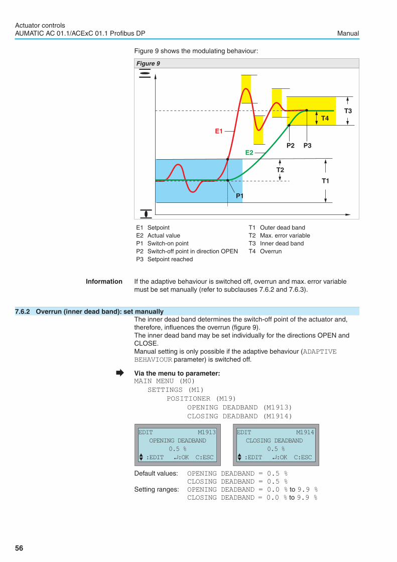
Figure 9 shows the modulating behaviour:
Information If the adaptive behaviour is switched off, overrun and max. error variablemust be set manually (refer to subclauses 7.6.2 and 7.6.3).
7.6.2 Overrun (inner dead band): set manuallyThe inner dead band determines the switch-off point of the actuator and,therefore, influences the overrun (figure 9).The inner dead band may be set individually for the directions OPEN andCLOSE.Manual setting is only possible if the adaptive behaviour (ADAPTIVEBEHAVIOUR parameter) is switched off.
� Via the menu to parameter:MAIN MENU (M0)
SETTINGS (M1)
POSITIONER (M19)
OPENING DEADBAND (M1913)
CLOSING DEADBAND (M1914)
Default values: OPENING DEADBAND = 0.5 %
CLOSING DEADBAND = 0.5 %
Setting ranges: OPENING DEADBAND = 0.0 % to 9.9 %
CLOSING DEADBAND = 0.0 % to 9.9 %
56
Actuator controlsAUMATIC AC 01.1/ACExC 01.1 Profibus DP Manual
E1 Setpoint T1 Outer dead bandE2 Actual value T2 Max. error variableP1 Switch-on point T3 Inner dead bandP2 Switch-off point in direction OPEN T4 OverrunP3 Setpoint reached
EDIT M1914
CLOSING DEADBAND
0.5 %
� :EDIT �:OK C:ESC
EDIT M1913
OPENING DEADBAND
0.5 %
� :EDIT �:OK C:ESC
E1
P1
P2
T1
T4
T2
T3
P3E2
Figure 9

7.6.3 Max. error variable (outer dead band): set manuallyThe outer deadband determines the switching-on point of the actuator.The motor starts if the actual value (input signal E2) or a change in nominalvalue is higher than the max. error variable determined by the outer deadband (refer to figure 9). Manual setting is only possible if the adaptivebehaviour (ADAPTIVE BEHAVIOUR parameter) is switched off.
� Via the menu to parameter:MAIN MENU (M0)
SETTINGS (M1)
POSITIONER (M19)
OUTER DEADBAND (M1915)
Default value: 1.0 %
Setting range: 0.1 % to 9.9 %
7.6.4 Dead time settingThe dead time prevents the operation to a new nominal position within apre-determined time.
� Via the menu to parameter:MAIN MENU (M0)
SETTINGS (M1)
POSITIONER (M19)
DEAD TIME (M1910)
Default value: 0.5 sSetting range: 0.0 to 60.0 seconds
Information It must be ensured via the controls that the max. permissible number ofstarts of the actuator is not exceeded. This can be achieved by setting thedead time to a sufficiently high value.
57
Actuator controlsManual AUMATIC AC 01.1/ACExC 01.1 Profibus DP
EDIT M1915
OUTER DEADBAND
1.0 %
� :EDIT �:OK C:ESC
EDIT M1910
DEAD TIME (T-OFF)
0.5 s
� :EDIT �:OK C:ESC

7.6.5 Closing fully/opening fully (end position tolerance for setpoint E1)
If the end positions cannot be reached due to inaccurate analogue setpointsignals (0/4 mA or 20 mA), a tolerance for the nominal value within the endposition range can be set. If the tolerance is exceeded or not reached, theactuator continues the operation until the full end position has beenreached. This ensures that the actuator opens and closes fully.
Information The tolerance ranges are not effective if the operation commands are trans-ferred to the actuator as fieldbus telegrams. In this case the actuator runscompletely CLOSED as soon as it receives the nominal value 0 % and com-pletely OPEN as soon as it receives the nominal value 100.0 %.
� Via the menu to parameter:MAIN MENU (M0)
SETTINGS (M1)
POSITIONER (M19)
FULL OPEN ADJUST (M1911)
FULL CLOSE ADJUST (M1912))
Default values: FULL OPEN ADJUST = 100 %
FULL CLOSE ADJUST = 0 %
Setting ranges: FULL OPEN ADJUST = 95 % to 100 % of travelFULL CLOSE ADJUST = 0 % to 50 % of travel
7.6.6 Open-close duty (REMOTE MODE) and modulating duty (SETPOINT MODE) selectionIn standard version, the change-over between open-close and modulatingduty is made via fieldbus (channel 1 or channel 2) using command bits inthe process representation output. Only one command bit may be set at anyone time. No operation is performed if several command bits are set.
SETPOINT MODE command bit = 1 corresponds to modulating duty:The actuator reacts to the setpoint E1 transmitted via the fieldbus.
Remote OPEN or Remote CLOSE command bits = 1:The actuator runs in direction OPEN or CLOSE.
The following versions also allow a change-over between open-close andmodulating duty via the MODE input (refer to wiring diagram):. in addition to the Profibus DP interface, the AUMATIC is equipped with a
further parallel interface (refer to page 83). the AUMATIC is equipped with additional control inputs (refer to page 80).
MODE input: + 24 V DC = REMOTE MODE = open-close duty, i.e. thecontrol is executed via commands OPEN - STOP - CLOSE
MODE input: 0 V (or input open) = SETPOINT = modulating duty, i.e. thecontrol is executed via an analogue signal (e.g. 0/4 – 20 mA)
58
Actuator controlsAUMATIC AC 01.1/ACExC 01.1 Profibus DP Manual
EDIT M1912
FULL CLOSE ADJUST
0 %
� :EDIT �:OK C:ESC
EDIT M1911
FULL OPEN ADJUST
100 %
� :EDIT �:OK C:ESC

7.6.7 Source of setpoint E1: viewThis value is set in the factory and can only be changed by the AUMA ser-vice.
� Via the menu to parameter:MAIN MENU (M0)
CONFIGURATION (M4)
SETUP (M41)
SETPOINT E1 (M4100)
Default value: DP
� Description of the parameter settings:
NONE
There is no setpoint source available.
LOGIC ANALOG IN1
For AUMA service only (the setpoint E1 is transmitted from external via theanalogue input 1 directly to the logic board.
I/O1 ANALOG IN1
The setpoint E1 is transmitted via the I/O interface board, analogue input 1.
I/O1 ANALOG IN2
The setpoint E1 is transmitted via the I/O interface board, analogue input 2.
DP
The setpoint E1 is transmitted via the Profibus DP interface board, channel1 or channel 2.
DP1 ANALOG IN1
The setpoint E1 is transmitted via the Profibus DP interface board, analogueinput 1.
DP1 ANALOG IN2
The setpoint E1 is transmitted via the Profibus DP interface board, analogueinput 2.
DP2 ANALOG IN1
The setpoint E1 is transmitted via the second Profibus DP interface board,analogue input 1.
DP2 ANALOG IN2
The setpoint E1 is transmitted via the second Profibus DP interface board,analogue input 2.
59
Actuator controlsManual AUMATIC AC 01.1/ACExC 01.1 Profibus DP
VIEW
SETPOINT E1
DP
C:ESC

7.6.8 Input range of setpoint 1: view/editThe parameters of this setting depend on the pre-set setpoint source(SETPOINT E1 (M4100) parameter, page 59).
Initial and end value via the Profibus DP interfaceIn Profibus DP standard version, the setpoint E1 is transmitted via the pro-cess representation.The input range is 0 – 100 percent or 0 – 1,000 per mil. The change-overbetween percent and per mil is made via the “Format of analogue Indica-tions” parameter in the GSD file.
Initial and end value via I/O interfaceOptionally, setpoint E1 can be transmitted via an analogue input instead ofthe fieldbus (channel 1 or channel 2). This is possible for the following ver-sions:a) in addition to the Profibus DP interface, the AUMATIC is equipped with a
further parallel interface (refer to page 83)b) the AUMATIC is equipped with additional control inputs (refer to page 80)The input range amounts to 0/4 – 20 mA. It is possible to modify the inputrange via the display for both versions:
Version a) for setpoint source from parallel interface, analogue input 1:
� Via the menu to parameter:MAIN MENU (M0)
CONFIGURATION (M4)
SETUP (M41)
I/O1 ANLOG IN1 START (M410H)
I/O1 ANLOG IN1 END (M410I)
Default values: I/O1 ANLOG IN1 START = 0 mAI/O1 ANLOG IN1 END = 20 mA
Setting ranges: I/O1 ANLOG IN1 START = 0 to 20 mAI/O1 ANLOG IN1 END = 0 to 20 mA
Version b) for setpoint source Profibus DP, analogue input 1
� Via the menu to parameter:MAIN MENU (M0)
CONFIGURATION (M4)
SETUP (M41)
DP1 ANLOG IN1 START (M410L)
DP1 ANLOG IN1 END (M410M)
Default values: DP1 ANLOG IN2 END = 0 mADP1 ANLOG IN1 END = 20 mA
Setting ranges: DP1 ANLOG IN1 START = 0 to 20 mADP1 ANLOG IN1 END = 0 to 20 mA
Information If the measuring values are 0.3 mA below the initial value a wire break isindicated as a warning.
60
Actuator controlsAUMATIC AC 01.1/ACExC 01.1 Profibus DP Manual
VIEW
I/O1 ANLOG IN1 END
20 mA
C:ESC
VIEW
I/O1 ANLOG IN1 START
0.0 mA
C:ESC
VIEW
DP1 ANLOG IN1 END
20.0 mA
C:ESC
VIEW
DP1 ANLOG IN1 START
0.0 mA
C:ESC

7.7 Process controller (option)
Figure 10 shows the function of the process controller:The process controller (2) receives the process setpoint (E1) and the processvariable (E4) (e.g. from a sensor). On the basis of both values, the processcontroller calculates the position setpoint (E7) for the positioner (3).In turn, the positioner (3) compares this setpoint with the position feedback(E2) of the valve and issues the operation commands (OPEN - CLOSE) tothe actuator.
Table of contents:7.7.1 Setting procedure7.7.2 Process controller activation7.7.3 Proportional amplification Kp setting7.7.4 Reset time Ti setting7.7.5 Rate time Td setting7.7.6 Derivative gain Kd setting7.7.7 Internal process setpoint setting7.7.8 Behaviour on loss of the process setpoint (wire break monitoring)7.7.9 Inverse operation setting7.7.10 Travel limitation7.7.11 Reaction monitoring setting7.7.12 Input range of process setpoint E1: view7.7.13 Input range of process variable E4: view
61
Actuator controlsManual AUMATIC AC 01.1/ACExC 01.1 Profibus DP
E1E4
2
E2
6
7
4
1
3
5
E7
Figure 10
1 AUMATIC controls 7 Valve2 Process controller3 Positioner E1 Process setpoint4 Actuator E2 Position feedback5 Positioner e.g. RWG/MWG E4 Process variable6 Sensor E7 Position setpoint (internal)
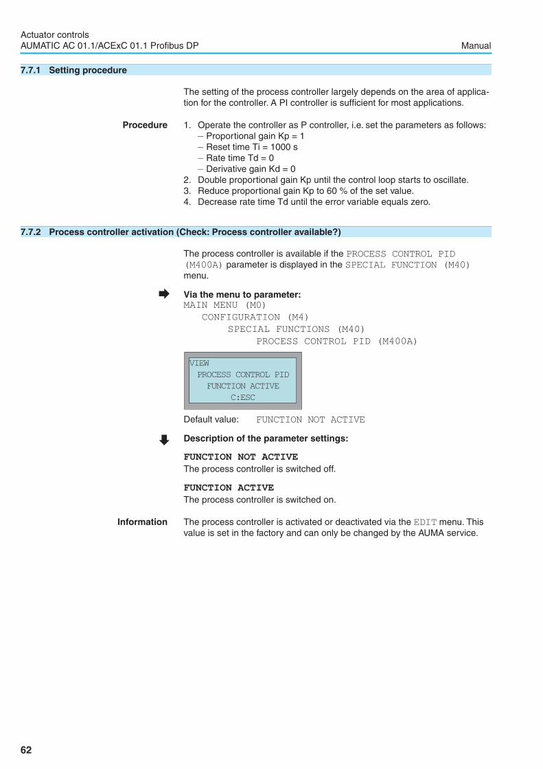
7.7.1 Setting procedure
The setting of the process controller largely depends on the area of applica-tion for the controller. A PI controller is sufficient for most applications.
Procedure 1. Operate the controller as P controller, i.e. set the parameters as follows:– Proportional gain Kp = 1– Reset time Ti = 1000 s– Rate time Td = 0– Derivative gain Kd = 0
2. Double proportional gain Kp until the control loop starts to oscillate.3. Reduce proportional gain Kp to 60 % of the set value.4. Decrease rate time Td until the error variable equals zero.
7.7.2 Process controller activation (Check: Process controller available?)
The process controller is available if the PROCESS CONTROL PID
(M400A) parameter is displayed in the SPECIAL FUNCTION (M40)
menu.
� Via the menu to parameter:MAIN MENU (M0)
CONFIGURATION (M4)
SPECIAL FUNCTIONS (M40)
PROCESS CONTROL PID (M400A)
Default value: FUNCTION NOT ACTIVE
� Description of the parameter settings:
FUNCTION NOT ACTIVE
The process controller is switched off.
FUNCTION ACTIVE
The process controller is switched on.
Information The process controller is activated or deactivated via the EDIT menu. Thisvalue is set in the factory and can only be changed by the AUMA service.
62
Actuator controlsAUMATIC AC 01.1/ACExC 01.1 Profibus DP Manual
VIEW
PROCESS CONTROL PID
FUNCTION ACTIVE
C:ESC
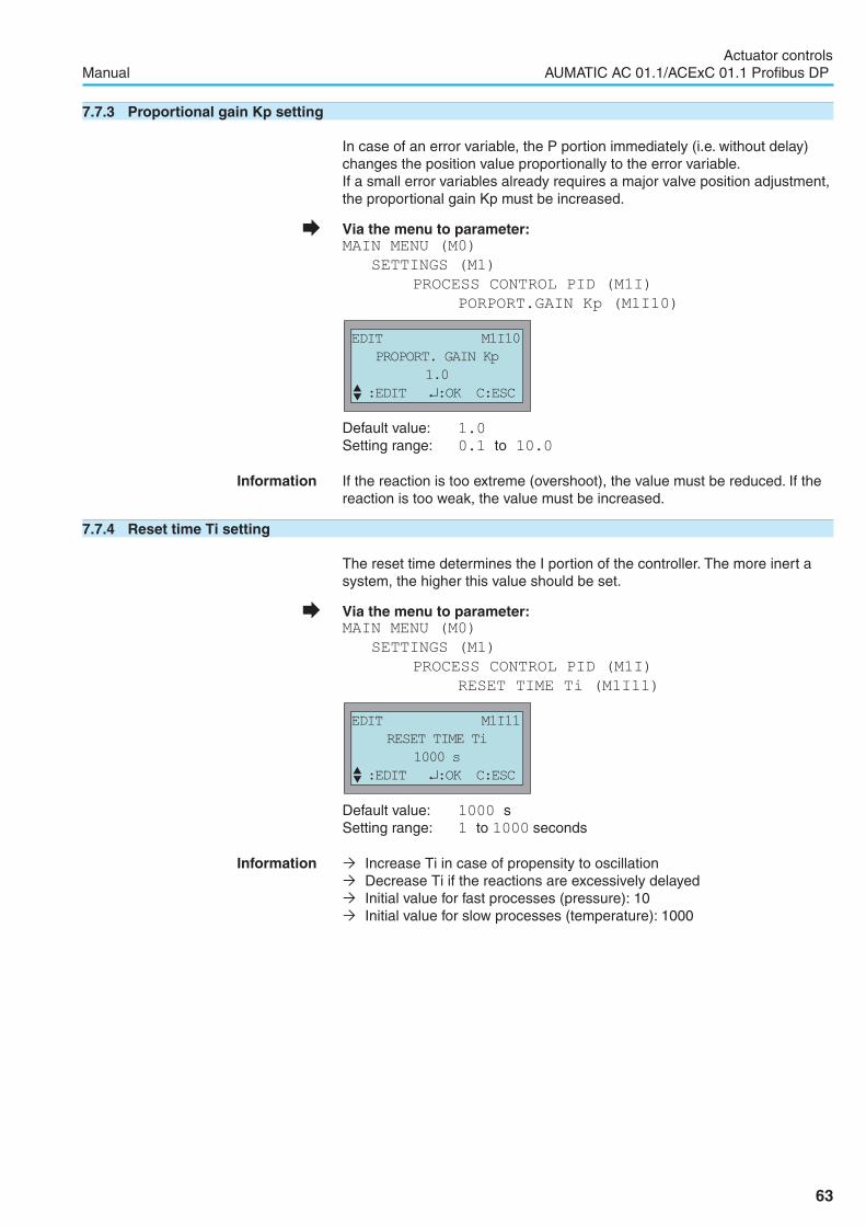
7.7.3 Proportional gain Kp setting
In case of an error variable, the P portion immediately (i.e. without delay)changes the position value proportionally to the error variable.If a small error variables already requires a major valve position adjustment,the proportional gain Kp must be increased.
� Via the menu to parameter:MAIN MENU (M0)
SETTINGS (M1)
PROCESS CONTROL PID (M1I)
PORPORT.GAIN Kp (M1I10)
Default value: 1.0
Setting range: 0.1 to 10.0
Information If the reaction is too extreme (overshoot), the value must be reduced. If thereaction is too weak, the value must be increased.
7.7.4 Reset time Ti setting
The reset time determines the I portion of the controller. The more inert asystem, the higher this value should be set.
� Via the menu to parameter:MAIN MENU (M0)
SETTINGS (M1)
PROCESS CONTROL PID (M1I)
RESET TIME Ti (M1I11)
Default value: 1000 sSetting range: 1 to 1000 seconds
Information � Increase Ti in case of propensity to oscillation� Decrease Ti if the reactions are excessively delayed� Initial value for fast processes (pressure): 10� Initial value for slow processes (temperature): 1000
63
Actuator controlsManual AUMATIC AC 01.1/ACExC 01.1 Profibus DP
EDIT M1I11
RESET TIME Ti
1000 s
� :EDIT �:OK C:ESC
EDIT M1I10
PROPORT. GAIN Kp
1.0
� :EDIT �:OK C:ESC

7.7.5 Rate time Td settingThe rate time determines the D portion of the controller. Typically, no settingis required here (= 0), since actuator and valve – due to the operating time –cannot react abruptly to a sudden occurrence of an error variable.
� Via the menu to parameter:MAIN MENU (M0)
SETTINGS (M1)
PROCESS CONTROL PID (M1I)
RATE TIME Td (M1I12)
Default value: 0 sSetting range: 0 to 100 seconds
Information � Increase Td in case of propensity to oscillation� Initial value for actuators: 0
7.7.6 Derivative gain Kd settingThe derivative gain determines the D portion of the controller.Typically, no setting isrequired here (= 0), since the actuator and valve – due to the operating time - can-not react abruptly to a sudden occurrence of an error variable.
� Via the menu to parameter:MAIN MENU (M0)
SETTINGS (M1)
PROCESS CONTROL PID (M1I)
DERIVATIVE GAIN Kd (M1I13)
Default value: 0
Setting range: 0 to 100
64
Actuator controlsAUMATIC AC 01.1/ACExC 01.1 Profibus DP Manual
EDIT M1I13
DERIVATIVE GAIN Kd
0
� :EDIT �:OK C:ESC
EDIT M1I12
RATE TIME Td
0 s
� :EDIT �:OK C:ESC

7.7.7 Internal process setpoint settingIf necessary, the process controller can also be operated without externalprocess setpoint. An internal process setpoint may be set with this parame-ter.
� Via the menu to parameter:MAIN MENU (M0)
SETTINGS (M1)
PROCESS CONTROL PID (M1I)
INTERNAL SET POINT (M1I14)
Default value: 0 %
Setting range: 0 to 100 %
Information The actuator only reacts to the preset internal setpoint if the PID TYPE
parameter is set to PID-INTERN.
� Via the menu to parameter:MAIN MENU (M0)
SETTINGS (M1)
PROCESS CONTROL PID (M1I)
PID TYPE (M1I1C)
Default value: PID-EXTERN
� Description of the parameter settings:
PID-INTERN
Process control via internal process setpoint
PID-EXTERN
Process control via external process setpoint
65
Actuator controlsManual AUMATIC AC 01.1/ACExC 01.1 Profibus DP
EDIT M1I1C
PID TYPE
PID-EXTERN
� :EDIT �:OK C:ESC
EDIT M1I14
INTERNAL SET POINT
0 %
� :EDIT �:OK C:ESC

7.7.8 Behaviour on loss of the process setpoint (wire break monitoring)
When using 4 – 20 mA signals for the process setpoint and the positionfeedback, wire break monitoring is performed.Loss of the process variable starts the failure behaviour.
� Via the menu to parameter:MAIN MENU (M0)
SETTINGS (M1)
PROCESS CONTROL PID (M1I)
BEHAVIOUR-LOSS OF E1 (M1I15)
Default value: PID-INTERN
� Description of the parameter settings:
PID-INTERN
In case of signal loss of the process setpoint, the controls switch to theinternal process setpoint.
FAILURE BEHAVIOUR
The failure behaviour is activated for signal loss process setpoint (page 41).The failure behaviour defines whether the actuator stops or remains in posi-tion, whether the valve opens or closes or approaches a parameter-definedintermediate position.
7.7.9 Inverse operation setting
As standard, the valve is opened by the modulating actuator as soon as theprocess variable falls below the process setpoint. Depending on the pro-cess, it may, however, be necessary that the valve closes as soon as theprocess variable falls below the process setpoint. In this case, the respectiveparameters are used to set the process controller to inverse operation.
� Via the menu to parameter:MAIN MENU (M0)
SETTINGS (M1)
PROCESS CONTROL PID (M1I)
INVERSE OPERATION (M1I16)
Default value: FUNCTION NOT ACTIVE
� Description of the parameter settings:
FUNCTION NOT ACTIVE
Inverse operation is switched off (default).
FUNCTION ACTIVE
Inverse operation is switched on.
66
Actuator controlsAUMATIC AC 01.1/ACExC 01.1 Profibus DP Manual
EDIT M1I16
INVERSE OPERATION
FUNCTION NOT ACTIVE
� :EDIT �:OK C:ESC
EDIT M1I15
BEHAVIOUR-LOSS OF E1
PID-INTERN
� :EDIT �:OK C:ESC

7.7.10 Travel limitation
If necessary, the travel can be limited in direction OPEN and/or CLOSE.This prevents the end position(s) OPEN and/or CLOSED from beingapproached in modulating duty. The actuator stops when reaching the setposition limit value. In operation mode LOCAL or REMOTE MODE, this limi-tation is not active. The valve can then be run into the end positions eithervia the local controls or the remote control commands OPEN - CLOSE.
Figure 11 shows the limitation of the travel range:
� Via the menu to parameter:MAIN MENU (M0)
SETTINGS (M1)
PROCESS CONTROL PID (M1I)
CONTROL LIMIT OPEN (M1I17)
CONTROL LIMIT CLOSE (M1I18))
Default values: CONTROL LIMIT OPEN = 100 %
CONTROL LIMIT CLOSE = 0 %
Setting ranges: CONTROL LIMIT OPEN = 0 % to 100 %
CONTROL LIMIT CLOSE = 0 % to 100 %
67
Actuator controlsManual AUMATIC AC 01.1/ACExC 01.1 Profibus DP
EDIT M1I18
CONTROL LIMIT CLOSE
0 %
� :EDIT �:OK C:ESC
EDIT M1I17
CONTROL LIMIT OPEN
100 %
� :EDIT �:OK C:ESC
1 Permissible actuator travel for PIDoperation 2
Permissible actuator travel foroperation modes LOCAL orREMOTE MODE
0 % 100 %
67 %22 %
1
2
Figure 11

7.7.11 Reaction monitoring setting
In addition to wire break monitoring, the process variable can also be sub-ject to reaction monitoring.
Response monitoring Via E4 MAX. REACTION parameter.If the process variable (E4) exceeds the maximum value within the reactiontime (t1), the failure behaviour is activated (page 41).
Change monitoring Via E4 MIN. REACTION parameter.If, after a process setpoint change, the process variable (E4) does notchange by the min. value within reaction time (t1), the failure behaviour isactivated (page 41).The change monitoring allows to check whether the system reacts to anominal value change.
Figure 12 shows the reaction monitoring of the process variable:
Information If the parameter E4 REACTION TIME is set to 0, the reaction monitoring isnot working.
� Via the menu to parameter:MAIN MENU (M0)
SETTINGS (M1)
PROCESS CONTROL PID (M1I)
E4 REACTION TIME (M1I19)
E4 MIN. REACTION (M1I1A)
E4 MAX. REACTION (M1I1B)
Default values: E4 REACTION TIME = 0 sE4 MIN. REACTION = 0.0 %
E4 MAX. REACTION = 0.0 %
Setting ranges: E4 REACTION TIME = 0 to 100 secondsE4 MIN. REACTION = 0.0 % to 10.0 %
E4 MAX. REACTION = 0.0 % to 10.0 %
68
Actuator controlsAUMATIC AC 01.1/ACExC 01.1 Profibus DP Manual
EDIT M1I19
E4 REACTION TIME
0 s
� :EDIT �:OK C:ESC
E4 Process setpoint P1 Response monitoringt1 Reaction time, e.g. = 1 s P2 Change monitoring
t
E4
P1
t1
P2
Figure 12

7.7.12 Input range of process setpoint E1: viewRefer to subclause Positioner “ Input range of setpoint value E1: view/edit”(page 60).
7.7.13 Input range of process variable E4: view/editIn Profibus DP standard version, the process variable E4 is transmitted viaan additional analogue 0/4 – 20 mA input (wiring diagram designation =ANIN2).The input range is determined by an initial and an end value.
� Via the menu to parameter:MAIN MENU (M0)
CONFIGURATION (M4)
SETUP (M41)
DP1 ANLOG IN2 START (M411N)
DP1 ANLOG IN2 END (M411P)
Default values: DP1 ANLOG IN2 START = 0 mADP1 ANLOG IN2 END = 20 mA
Setting ranges: DP1 ANLOG IN2 START = 0 mA to 20 mADP1 ANLOG IN2 END = 0 mA to 20 mA
Information . If the measuring values are 0.3 mA below the initial value, a wire breakis indicated as a warning.
69
Actuator controlsManual AUMATIC AC 01.1/ACExC 01.1 Profibus DP
VIEW
DP1 ANLOG IN2 END
20.0 mA
C:ESC
VIEW
DP1 ANLOG IN2 START
0.0 mA
C:ESC

7.8 Stepping mode (option)
In stepping mode the operating time can be increased for the entire or anyportion of the valve travel (refer to figure 13).
Information Stepping mode is only possible if a position transmitter (potentiometer,RWG, or MWG) is installed in the actuator.
Table of contents:7.8.1 Display indication: enable view7.8.2 Stepping mode: switch on or off7.8.3 Stepping range setting (start and end of stepping mode)
ON and OFF times setting
7.8.1 Display indication: enable viewTo perform settings for stepping mode via the display, the STEPPING MODE
setting must be in position VIEW ENABLED.
� Via the menu to parameter:MAIN MENU (M0)
CONFIGURATION (M4)
SPECIAL FUNCTIONS (M40)
STEPPING MODE (M4014)
Default value: VIEW NOT ENABLED
� Description of the parameter settings:
VIEW NOT ENABLED
The parameters for the stepping mode are not indicated in the display.
VIEW ENABLED
The parameters for the stepping mode are indicated in the display.
70
Actuator controlsAUMATIC AC 01.1/ACExC 01.1 Profibus DP Manual
1
t1
t3
t4
t3
t4
t1
t2
t2
2
Figure 13
EDIT M4014
STEPPING MODE
VIEW NOT ENABLED
� :EDIT �:OK C:ESC
1 Stepping range OPEN t1 Operating time for normal operation2 Stepping range CLOSE t2 Operating time for stepping modeP1 Start of stepping mode t3 Running timeP2 Stop of stepping mode t4 OFF time (pause time)

7.8.2 Stepping mode: switch on or offStepping mode can be individually activated for the directions OPEN andCLOSE.
� Via the menu to parameter:MAIN MENU (M0)
SETTINGS (M1)
STEPPING MODE (M17)
DIRECTION OPEN (M1710)
DIRECTION CLOSE (M1715)
Default values: DIRECTION OPEN = OFF
DIRECTION CLOSE = OFF
� Description of the parameter settings:
OFF
Stepping mode is switched off
REMOTE ONLY
Stepping mode only possible in operation mode REMOTE
LOCAL ONLY
Stepping mode only possible in operation mode LOCAL
REMOTE AND LOCAL
Stepping mode possible in both operation modes REMOTE and LOCAL
7.8.3 Stepping range setting (start and end of stepping mode)The stepping range (start and end of stepping mode) can be set separatelyfor both directions.
� Via the menu to parameter:MAIN MENU (M0)
SETTINGS (M1)
STEPPING MODE (M17)
START STEP OPEN (M1713)
STOP STEP OPEN (M1714)
START STEP CLOSE (M1718)
STOP STEP CLOSE (M1719)
Default values: START STEP OPEN = 0.0 %
STOP STEP OPEN = 100.0 %
START STEP CLOSE = 100.0 %
STOP STEP CLOSE = 0.0 %
Setting ranges: START STEP OPEN = 0.0 % to 99.9 %
STOP STEP OPEN = 0.1 % to 1000 %
START STEP CLOSE = 0.1 % to 100.0 %
STOP STEP CLOSE = 0.0 %to 99.9 %
71
Actuator controlsManual AUMATIC AC 01.1/ACExC 01.1 Profibus DP
EDIT M1710
DIRECTION OPEN
OFF
� :EDIT �:OK C:ESC
EDIT M1714
STOP STEP OPEN
100.0 %
� :EDIT �:OK C:ESC
EDIT M1713
START STEP OPEN
0.0 %
� :EDIT �:OK C:ESC

7.8.4 ON and OFF times settingThe ON or OFF times can be set individually for the directions OPEN andCLOSE.
� Via the menu to parameter:MAIN MENU (M0)
SETTINGS (M1)
STEPPING MODE (M17)
ON TIME OPEN (M1711)
OFF TIME OPEN (M1712)
ON TIME CLOSE (M1716)
OFF TIME CLOSE (M1717)
Default values: ON TIME OPEN = 10.0 sOFF TIME OPEN = 50.0 sON TIME CLOSE = 10.0 sOFF TIME CLOSE = 50.0 s
Setting ranges: ON TIME OPEN = 1.0 to 300.0 secondsOFF TIME OPEN = 1.0 to 300.0 secondsON TIME CLOSE = 1.0 to 300.0 secondsOFF TIME CLOSE = 1.0 to 300.0 seconds
72
Actuator controlsAUMATIC AC 01.1/ACExC 01.1 Profibus DP Manual
EDIT M1712
OFF TIME OPEN
50.0 %
� :EDIT �:OK C:ESC
EDIT M1711
ON TIME OPEN
10.0 %
� :EDIT �:OK C:ESC

7.9 Local controls enable function (option)
The selector switch functions on the local controls (LOCAL, OFF, andREMOTE) may be either enabled or disabled.In addition, an automatic release can be programmed for the event of a busloss.
7.9.1 Selector switch functions: enable/disableThis value is set in the factory and can only be changed by the AUMA ser-vice.
� Via the menu to parameter:MAIN MENU (M0)
CONFIGURATION (M4)
SETUP (M41)
ENABLE LOCAL MODE (M410W)
Default value: NOT ACTIVE
� Description of the parameter settings:
NOT ACTIVE
All selector switch functions are enabled.
BUS
The selector switch is enabled via fieldbus.The AUMATIC can be set in such a way that the AUMATIC internal selectorswitch position may additionally be determined by 3 bits in the process rep-resentation output.If a selector switch is available, the signals via the bus have to match theactual selector switch position to enable a release. If there is no selectorswitch, the release is only controlled by the signals via bus.
BUS, AUTO LOCAL
The selector switch is enabled via fieldbus.This setting is only permissible if the local controls is equipped with a selec-tor switch.In case of bus failure, the selector switch positions LOCAL and OFF areenabled to allow actuator operation via the push buttons.
BUS, AUTO LOCAL II
The selector switch positions LOCAL and OFF are enabled via fieldbus.This setting is only permissible if the local controls is equipped with a selec-tor switch.If the command “AUMATIC changes to REMOTE” is sent, the internalAUAMTIC selector switch position is always REMOTE, irrespective of theactual selector switch position. In case of bus failure, the selector switchpositions LOCAL and OFF are enabled to allow actuator operation via thepush buttons.
Information Observe during commissioning and maintenance: Any control from RE-MOTE via the system cannot be interrupted or blocked locally via the selectorswitch position.
73
Actuator controlsManual AUMATIC AC 01.1/ACExC 01.1 Profibus DP
VIEW
ENABLE LOCAL MODE
NOT ACTIVE
C:ESC

BUS, AUTO REMOTE
The selector switch is enabled via fieldbus.This setting is only permissible if the local controls are equipped with aselector switch and if additional control inputs (option) are available.In case of bus failure, the selector switch position REMOTE is enabled toallow actuator operation via the additional control inputs from the controlroom.
BUS, AUTO
The selector switch is enabled via fieldbus.This setting is only permissible if the local controls are equipped with aselector switch.In case of bus failure, the selector switch positions LOCAL, OFF, andREMOTE are enabled. Depending on the selector switch position, the actua-tor may either be operated via the push buttons from LOCAL or via the con-trol room from REMOTE.
I/O
The digital RELEASE input (refer to wiring diagram ACP) is used to enableor disable the actuator operation via the push buttons.This setting is only permissible if the local controls are equipped with aselector switch (SELECTOR SWITCH = AVAILABLE parameter).. Disabling operation via push buttons:
no signal at the RELEASE input (the status indication S0 in the displayshows RESTRICTED).. Enabling operation via push buttons:Apply + 24 V DC signal at the RELEASE input.
74
Actuator controlsAUMATIC AC 01.1/ACExC 01.1 Profibus DP Manual
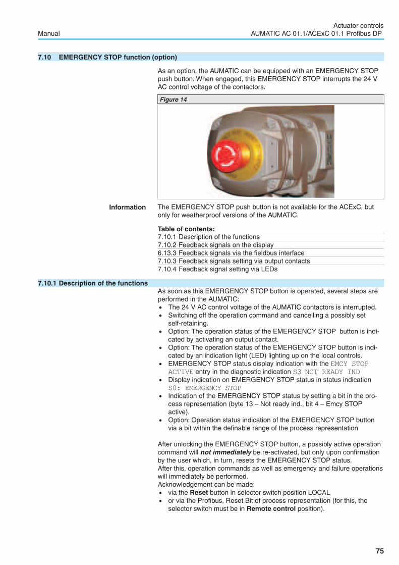
7.10 EMERGENCY STOP function (option)
As an option, the AUMATIC can be equipped with an EMERGENCY STOPpush button. When engaged, this EMERGENCY STOP interrupts the 24 VAC control voltage of the contactors.
Information The EMERGENCY STOP push button is not available for the ACExC, butonly for weatherproof versions of the AUMATIC.
Table of contents:7.10.1 Description of the functions7.10.2 Feedback signals on the display6.13.3 Feedback signals via the fieldbus interface7.10.3 Feedback signals setting via output contacts7.10.4 Feedback signal setting via LEDs
7.10.1 Description of the functionsAs soon as this EMERGENCY STOP button is operated, several steps areperformed in the AUMATIC:. The 24 V AC control voltage of the AUMATIC contactors is interrupted.. Switching off the operation command and cancelling a possibly set
self-retaining.. Option: The operation status of the EMERGENCY STOP button is indi-cated by activating an output contact.. Option: The operation status of the EMERGENCY STOP button is indi-cated by an indication light (LED) lighting up on the local controls.. EMERGENCY STOP status display indication with the EMCY STOP
ACTIVE entry in the diagnostic indication S3 NOT READY IND. Display indication on EMERGENCY STOP status in status indicationS0: EMERGENCY STOP. Indication of the EMERGENCY STOP status by setting a bit in the pro-cess representation (byte 13 – Not ready ind., bit 4 – Emcy STOPactive).. Option: Operation status indication of the EMERGENCY STOP buttonvia a bit within the definable range of the process representation
After unlocking the EMERGENCY STOP button, a possibly active operationcommand will not immediately be re-activated, but only upon confirmationby the user which, in turn, resets the EMERGENCY STOP status.After this, operation commands as well as emergency and failure operationswill immediately be performed.Acknowledgement can be made:. via the Reset button in selector switch position LOCAL. or via the Profibus, Reset Bit of process representation (for this, the
selector switch must be in Remote control position).
75
Actuator controlsManual AUMATIC AC 01.1/ACExC 01.1 Profibus DP
Figure 14

7.10.2 Feedback signals on the displayThe following indications are displayed in status indications S0 and S3 :
� Description of the indications:
EMERGENCY STOP/EMCY STOP ACTIVE
The EMERGENCY STOP button has been operated and has put theAUMATIC into the EMERGENCY STOP status. This status can only becancelled by unlocking the EMERGENCY STOP button and issuing a sub-sequent RESET command.
7.10.3 Feedback signals setting via output contacts
� Via the menu to parameter:MAIN MENU (M0)
SETTINGS (M1)
I/O 1 (M14)
OUTPUT CONTACT 1 - 5
� Description of the parameter settings:
EMCY STOP BUTTON
The selected output contact is activated, after the EMERGENCY STOP but-ton was operated.This signal can be cancelled by unlocking the EMERGENCY STOP button.
7.10.4 Feedback signal setting via LEDs
� Via the menu to parameter:MAIN MENU (M0)
SETTINGS (M1)
LOCAL CONTROLS (M13)
LED 1 - 4
� Description of the parameter settings:
EMCY STOP BUTTON
The selected LED is illuminated after the EMERGENCY STOP button wasoperated.This signal can be cancelled by unlocking the EMERGENCY STOP button.
76
Actuator controlsAUMATIC AC 01.1/ACExC 01.1 Profibus DP Manual
�NOT READY IND, S3
EMCY STOP ACTIVE
�EMERGENCY STOP S0
EDIT M1412
OUTPUT CONTACT 1
EMCY STOP BUTTON
� :EDIT �:OK C:ESC
EDIT M1313
LED 2
EMCY STOP BUTTON
� :EDIT �:OK C:ESC

7.11 Profibus DP interface (option)
The AUMATIC may be equipped with one or two (option) Profibus DP inter-faces. This sub-clause applies to both interfaces. However, only the firstinterface is described as an example.In the menu, the interfaces are designated as follows:1st Profibus DP interface = PROFIBUS DP 1
2nd Profibus DP interface = PROFIBUS DP 2
7.11.1 Bus address setting (slave address)
� Via the menu to parameter:MAIN MENU (M0)
SETTINGS (M1)
PROFIBUS DP 1 (M1B)
SLAVEADDRESS (M1B10)
Default value: 2
Setting range: 0 to 125
77
Actuator controlsManual AUMATIC AC 01.1/ACExC 01.1 Profibus DP
EDIT M1B10
SLAVEADDRESS
2
� :EDIT �:OK C:ESC

7.12 Redundant bus connection with component redundancy (option)
In addition to the first fieldbus interface, the AUMATIC actuator controls canbe equipped with a second fieldbus interface. The 2nd interface may beused to increase the operational safety. If one of the interfaces fails, theother interface automatically takes over (component redundancy).
7.12.1 Configuration check for the second fieldbus interfaceThis value is set in the factory.
� Via the menu to parameter:MAIN MENU (M0)
CONFIGURATION (M4)
SETUP (M41)
I/O STACK 2 (M410Q)
Default value: –
� Description of the parameter settings:
NONE
no interface available.
I/O
The second interface is a parallel interface (combination fieldbus/standardinterface, page 83).
DP
The second interface is a Profibus DP interface board.
7.12.2 Second fieldbus interface setting
The setting of the actuator address is identical to those of the first fieldbusinterface. They are described on page 77 et seqq.
The menu for the second fieldbus interface has to be selected from thedescriptions Via the menu to parameter, e.g. PROFIBUS DP 2 instead ofPROFIBUS DP 1.
78
Actuator controlsAUMATIC AC 01.1/ACExC 01.1 Profibus DP Manual
VIEW M410Q
I/O STACK 2
DP
C:ESC

7.13 Profibus DP-V1 services (option)
Apart from the cyclic DP-V0 process data exchange, the Profibus DP-V1services can establish an additional acyclic communication via the fieldbus.For further information refer to. Device integration with DTM (Device Type Manager) manual. Device integration with EDD (Electronic Device Description) manual for
Simatic PDM (Process Device Manager)
Enable viewing the display indicationTo be able to use the Profibus DP-V1 service function, the DP-V1SERVICES setting must be set to FUNCTION ACTIVE.This value is set in the factory.
� Via the menu to parameter:MAIN MENU (M0)
CONFIGURATION (M4)
SPECIAL FUNCTIONS (M40)
DP-V1 SERVICES (M4019)
Default value: FUNCTION NOT ACTIVE
� Description of the parameter settings:
FUNCTION NOT ACTIVE
The Profibus DP-V1 services are not available.
FUNCTION ACTIVE
The Profibus DP-V1 services are available.
79
Actuator controlsManual AUMATIC AC 01.1/ACExC 01.1 Profibus DP
EDIT M4019
DP-V1 SERVICES
FUNCTION NOT ACTIVE
� :EDIT �:OK C:ESC
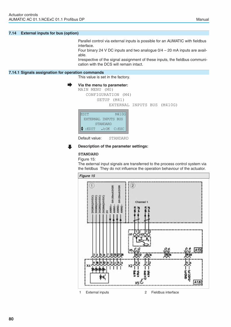
7.14 External inputs for bus (option)
Parallel control via external inputs is possible for an AUMATIC with fieldbusinterface.Four binary 24 V DC inputs and two analogue 0/4 – 20 mA inputs are avail-able.Irrespective of the signal assignment of these inputs, the fieldbus communi-cation with the DCS will remain intact.
7.14.1 Signals assignation for operation commandsThis value is set in the factory.
� Via the menu to parameter:MAIN MENU (M0)
CONFIGURATION (M4)
SETUP (M41)
EXTERNAL INPUTS BUS (M410G)
Default value: STANDARD
� Description of the parameter settings:
STANDARD
Figure 15:The external input signals are transferred to the process control system viathe fieldbus They do not influence the operation behaviour of the actuator.
80
Actuator controlsAUMATIC AC 01.1/ACExC 01.1 Profibus DP Manual
Figure 15
EDIT M410G
EXTERNAL INPUTS BUS
STANDARD
� :EDIT �:OK C:ESC
1 External inputs 2 Fieldbus interface

OPEN CLOSE CONTROL
Figure 16:. Conventional control of the actuator is possible either in OPEN - CLOSEduty or in modulating duty (setpoint of 0/4 – 20 mA). Selection betweenopen - close and modulating duty is made via the MODE input (refer topage 58).. Operation commands can be issued via the fieldbus or via the externalinputs. Switch-over is made via BUS/REMOTE input (see below).
OPEN CLOSE ESD
Figure 17:. Actuator control is possible in open-close duty (OPEN - CLOSE - EMER-GENCY) only. Modulating duty is not possible.. Operation commands can be issued via the fieldbus or via the externalinputs. Switch-over is made via BUS/REMOTE input (see below).. Operation commands are made in push-to-run operation only.. If a voltage of 0 V is present at EMERGENCY input, the actuator per-forms the programmed EMERGENCY operation, irrespective of theBUS/REMOTE input.
81
Actuator controlsManual AUMATIC AC 01.1/ACExC 01.1 Profibus DP
1 External inputs 2 Fieldbus interface
Figure 16
Figure 17
1 External inputs 2 Fieldbus interface

OPEN CLOSE STOP
Figure 18:. Actuator control is possible in open-close duty (OPEN – CLOSE - STOP)only. Modulating duty is not possible.. Operation commands can be issued via the fieldbus or via the externalinputs. Switch-over is made via BUS/REMOTE input (see below).. Operation commands are made in self-retaining only.
Information In the event of loss of bus communication, the external inputs do not auto-matically take over!
Information Please refer to the AUMATIC AC 01.1/ACExC 01.1 Profibus DP manual(Device integration Fieldbus) for details on feedback signals.
Switching between operation commands via fieldbus and external inputs� Apply 0 V DC (input open) at BUS/REMOTE input:
Controls react to fieldbus signals only.� Apply + 24 V DC at BUS/REMOTE input.
Controls reacts to external input signals only:MODE, CLOSE, OPEN, STOP, EMERGENCY, ANIN1 (the availableexternal inputs depend on the parameter setting).
82
Actuator controlsAUMATIC AC 01.1/ACExC 01.1 Profibus DP Manual
Figure 18
1 External inputs 2 Fieldbus interface

7.15 Combination fieldbus/standard interface (option)
The actuator controls is equipped with both a fieldbus interface and a paral-lel interface, if the I/O STACK 2 parameter status shows I/O.
� Via the menu to parameter:MAIN MENU (M0)
CONFIGURATION (M4)
SETUP (M41)
I/O STACK 2 (M410Q)
Figure 20 shows an extract of the wiring diagram with fieldbus interface (1)and parallel interface (2):
Switching between operation commands via fieldbus and parallelinputs� Apply 0 V DC (input open) at BUS/REMOTE input:
Controls react to fieldbus signals only.� Apply + 24 V DC (optional 115 V AC) at BUS/REMOTE input.
Controls reacts to parallel interface signals only:MODE, CLOSE, OPEN, STOP, EMERGENCY, ANIN1+, ANIN1–
Information If a voltage of 0 V is present at the EMERGENCY input, the actuator per-forms the set EMERGENCY operation (refer to page 38), irrespective of theBUS/REMOTE input.
Information In the event of loss of bus communication, the external inputs do not auto-matically take over!
Information Please refer to the AUMATIC AC 01.1/ACExC 01.1 Profibus DP manual(fieldbus device integration) for details on feedback signals.
83
Actuator controlsManual AUMATIC AC 01.1/ACExC 01.1 Profibus DP
VIEW
I/O STACK 2
I/O
C:ESC
Figure 20
1 Fieldbus interface 2 Parallel interface
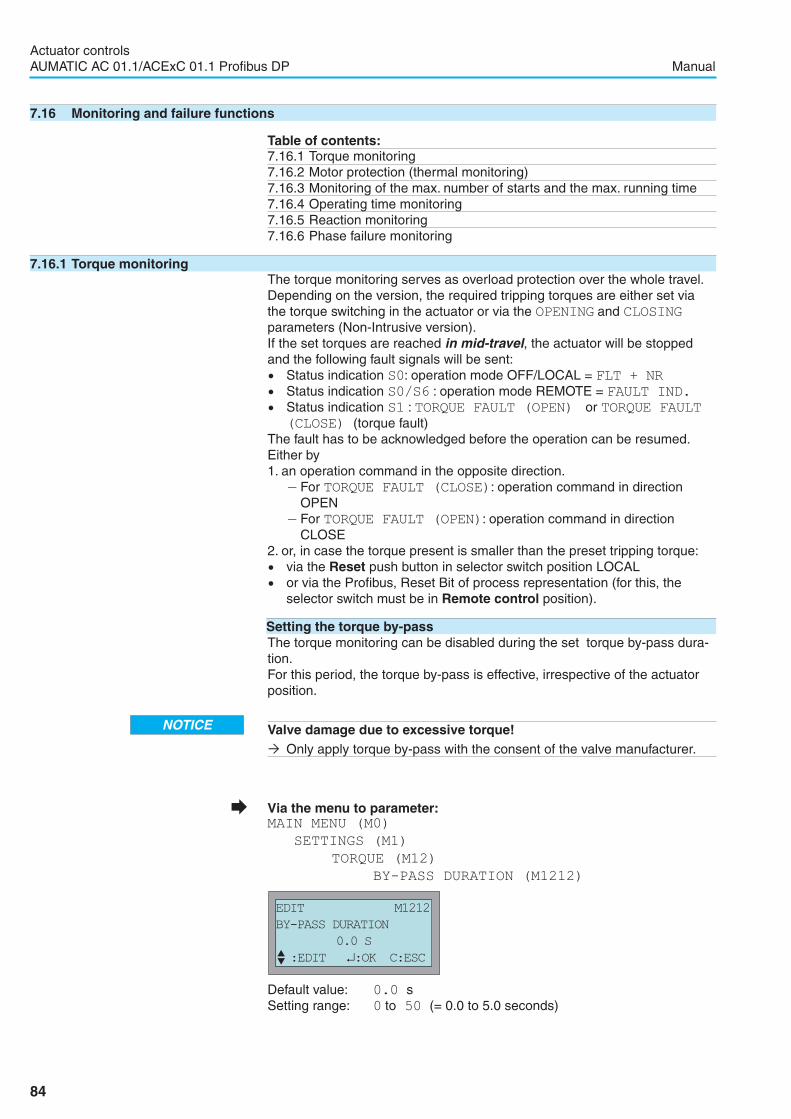
7.16 Monitoring and failure functions
Table of contents:7.16.1 Torque monitoring7.16.2 Motor protection (thermal monitoring)7.16.3 Monitoring of the max. number of starts and the max. running time7.16.4 Operating time monitoring7.16.5 Reaction monitoring7.16.6 Phase failure monitoring
7.16.1 Torque monitoringThe torque monitoring serves as overload protection over the whole travel.Depending on the version, the required tripping torques are either set viathe torque switching in the actuator or via the OPENING and CLOSINGparameters (Non-Intrusive version).If the set torques are reached in mid-travel, the actuator will be stoppedand the following fault signals will be sent:. Status indication S0: operation mode OFF/LOCAL = FLT + NR. Status indication S0/S6 : operation mode REMOTE = FAULT IND.. Status indication S1 : TORQUE FAULT (OPEN) or TORQUE FAULT
(CLOSE) (torque fault)The fault has to be acknowledged before the operation can be resumed.Either by1. an operation command in the opposite direction.
– For TORQUE FAULT (CLOSE): operation command in directionOPEN
– For TORQUE FAULT (OPEN): operation command in directionCLOSE
2. or, in case the torque present is smaller than the preset tripping torque:. via the Reset push button in selector switch position LOCAL. or via the Profibus, Reset Bit of process representation (for this, theselector switch must be in Remote control position).
Setting the torque by-passThe torque monitoring can be disabled during the set torque by-pass dura-tion.For this period, the torque by-pass is effective, irrespective of the actuatorposition.
� Via the menu to parameter:MAIN MENU (M0)
SETTINGS (M1)
TORQUE (M12)
BY-PASS DURATION (M1212)
Default value: 0.0 sSetting range: 0 to 50 (= 0.0 to 5.0 seconds)
84
Actuator controlsAUMATIC AC 01.1/ACExC 01.1 Profibus DP Manual
EDIT M1212
BY-PASS DURATION
0.0 S
� :EDIT �:OK C:ESC
Valve damage due to excessive torque!� Only apply torque by-pass with the consent of the valve manufacturer.
NOTICE

7.16.2 Motor protection (thermal monitoring)In order to protect against overheating and impermissibly high temperaturesat the actuator, PTC thermistors or thermoswitches are embedded in themotor winding. The thermoswitch is tripped as soon as the max. permissiblewinding temperature has been reached.The actuator is switched off and the following signals are given:. LED 3 (thermal fault) on the local controls is illuminated.. Status indication S0: operation mode OFF/LOCAL = FLT + NR. Status indication S0/S6: operation mode REMOTE = FAULT IND.. Status indication S1 in the display: THERMAL FAULT.
The motor has to cool down before the operation can be resumed.Depending on the parameter setting, the fault signal is either automaticallyreset or the fault signal has to be acknowledged.
Acknowledgement can be made:. via the Reset button in selector switch position LOCAL. or via the Profibus, Reset Bit of process representation (for this, theselector switch must be in Remote control position).
Viewing the motor protectionThis value is set in the factory.
� Via the menu to parameter:MAIN MENU (M0)
CONFIGURATION (M4)
SETUP (M41)
MOTOR PROTECTION (M4108)
Default values: Non Ex actuators = THERMAL CONT.(AUTO)
Ex actuators = THERMISTOR (RESET)
� Description of the parameter settings:
THERMAL CONT. (AUTO)
Automatic reset after the motor has cooled down.Not possible for explosion-proof version ACExC 01.1
THERMAL CONT. (RESET)
Manual reset. After the motor has cooled down the fault must be reset,either. via the Reset push button at the local controls, or. with the RESET command via the fieldbus.If required the thermal overload relay has to be reset manually. To this end,remove the cover on the back of the AUMATIC and operate the Reset but-ton on the thermal overload relay.
THERMISTOR (RESET)
Manual reset. After the motor has cooled down the fault must be reset,either. via the Reset push button at the local controls, or. with the RESET command via the fieldbus.
THERMISTOR (AUTO)
Automatic reset after the motor has cooled down.Not possible for explosion-proof version ACExC 01.1
85
Actuator controlsManual AUMATIC AC 01.1/ACExC 01.1 Profibus DP
VIEW
MOTOR PROTECTION
THERMAL CONT. (AUTO)
C:ESC
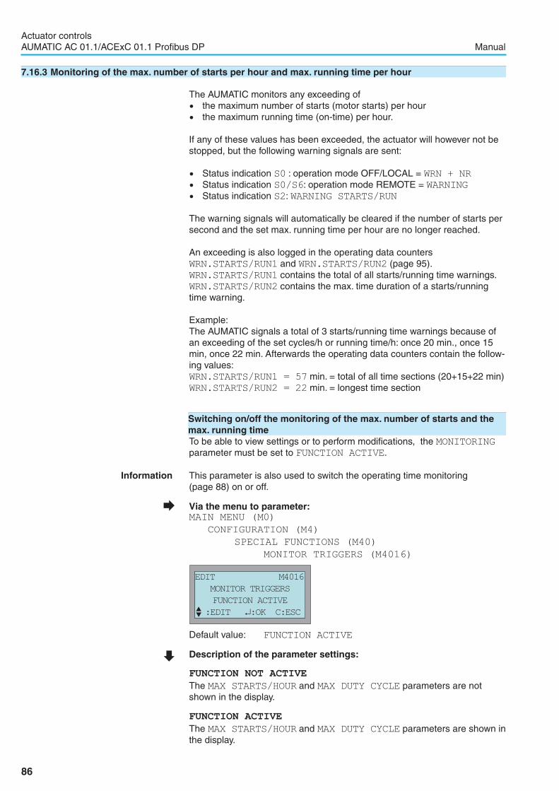
7.16.3 Monitoring of the max. number of starts per hour and max. running time per hour
The AUMATIC monitors any exceeding of. the maximum number of starts (motor starts) per hour. the maximum running time (on-time) per hour.
If any of these values has been exceeded, the actuator will however not bestopped, but the following warning signals are sent:
. Status indication S0 : operation mode OFF/LOCAL = WRN + NR. Status indication S0/S6: operation mode REMOTE = WARNING. Status indication S2: WARNING STARTS/RUN
The warning signals will automatically be cleared if the number of starts persecond and the set max. running time per hour are no longer reached.
An exceeding is also logged in the operating data countersWRN.STARTS/RUN1 and WRN.STARTS/RUN2 (page 95).WRN.STARTS/RUN1 contains the total of all starts/running time warnings.WRN.STARTS/RUN2 contains the max. time duration of a starts/runningtime warning.
Example:The AUMATIC signals a total of 3 starts/running time warnings because ofan exceeding of the set cycles/h or running time/h: once 20 min., once 15min, once 22 min. Afterwards the operating data counters contain the follow-ing values:WRN.STARTS/RUN1 = 57 min. = total of all time sections (20+15+22 min)WRN.STARTS/RUN2 = 22 min. = longest time section
Switching on/off the monitoring of the max. number of starts and themax. running timeTo be able to view settings or to perform modifications, the MONITORINGparameter must be set to FUNCTION ACTIVE.
Information This parameter is also used to switch the operating time monitoring(page 88) on or off.
� Via the menu to parameter:MAIN MENU (M0)
CONFIGURATION (M4)
SPECIAL FUNCTIONS (M40)
MONITOR TRIGGERS (M4016)
Default value: FUNCTION ACTIVE
� Description of the parameter settings:
FUNCTION NOT ACTIVE
The MAX STARTS/HOUR and MAX DUTY CYCLE parameters are notshown in the display.
FUNCTION ACTIVE
The MAX STARTS/HOUR and MAX DUTY CYCLE parameters are shown inthe display.
86
Actuator controlsAUMATIC AC 01.1/ACExC 01.1 Profibus DP Manual
EDIT M4016
MONITOR TRIGGERS
FUNCTION ACTIVE
� :EDIT �:OK C:ESC

Setting the max. permissible number of starts
� Via the menu to parameter:MAIN MENU (M0)
SETTINGS (M1)
MONITOR TRIGGERS (M18)
MAX STARTS/HOUR (M1810)
Default value: 1200
Setting range: 0 to 1800 starts (motor starts)
Setting the max. permissible running time
� Via the menu to parameter:MAIN MENU (M0)
SETTINGS (M1)
MONITOR TRIGGERS (M18)
MAX DUTY CYCLE (M1811)
Default value: 15 MIN
� Description of the parameter settings:
15 MIN
The max. permissible running time (on-time) per hour amounts to 15 min.
24 MIN
The max. permissible running time (on-time) per hour amounts to 24 min.
30 MIN
The max. permissible running time (on-time) per hour amounts to 30 min.
87
Actuator controlsManual AUMATIC AC 01.1/ACExC 01.1 Profibus DP
EDIT M1810
MAX STARTS/HOUR
1200
� :EDIT �:OK C:ESC
EDIT M1811
MAX DUTY CYCLE
15 min
� :EDIT �:OK C:ESC
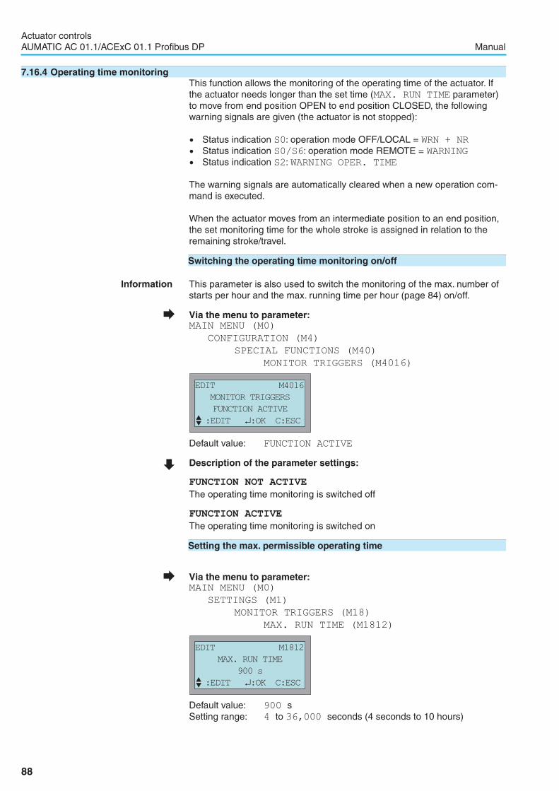
7.16.4 Operating time monitoringThis function allows the monitoring of the operating time of the actuator. Ifthe actuator needs longer than the set time (MAX. RUN TIME parameter)to move from end position OPEN to end position CLOSED, the followingwarning signals are given (the actuator is not stopped):
. Status indication S0: operation mode OFF/LOCAL = WRN + NR. Status indication S0/S6: operation mode REMOTE = WARNING. Status indication S2: WARNING OPER. TIME
The warning signals are automatically cleared when a new operation com-mand is executed.
When the actuator moves from an intermediate position to an end position,the set monitoring time for the whole stroke is assigned in relation to theremaining stroke/travel.
Switching the operating time monitoring on/off
Information This parameter is also used to switch the monitoring of the max. number ofstarts per hour and the max. running time per hour (page 84) on/off.
� Via the menu to parameter:MAIN MENU (M0)
CONFIGURATION (M4)
SPECIAL FUNCTIONS (M40)
MONITOR TRIGGERS (M4016)
Default value: FUNCTION ACTIVE
� Description of the parameter settings:
FUNCTION NOT ACTIVE
The operating time monitoring is switched off
FUNCTION ACTIVE
The operating time monitoring is switched on
Setting the max. permissible operating time
� Via the menu to parameter:MAIN MENU (M0)
SETTINGS (M1)
MONITOR TRIGGERS (M18)
MAX. RUN TIME (M1812)
Default value: 900 sSetting range: 4 to 36,000 seconds (4 seconds to 10 hours)
88
Actuator controlsAUMATIC AC 01.1/ACExC 01.1 Profibus DP Manual
EDIT M4016
MONITOR TRIGGERS
FUNCTION ACTIVE
� :EDIT �:OK C:ESC
EDIT M1812
MAX. RUN TIME
900 s
� :EDIT �:OK C:ESC

7.16.5 Reaction monitoringThe AUMATIC controls monitor the actuator reaction via the control unit ofthe actuator.If no reaction is recorded at the output drive of the actuator within a set time(REACTION TIME parameter), the actuator is switched off and the follow-ing fault signals are given:
. Status indication S0: operation mode OFF/LOCAL = FLT + NR. Status indication S0/S6: operation mode REMOTE = FAULT IND.. Status indication S1: INTERNAL FAULT. Diagnostic indication D2: NO REACTION
Reset the fault using either. the Reset push button at the local controls, or. the RESET command via the fieldbus.In case of operation from an intermediate position, reaction monitoring willonly be performed if the actuator has a position feedback.
Switching the reaction monitoring on/offThis value is set in the factory and can only be changed by the AUMA ser-vice.
� Via the menu to parameter:MAIN MENU (M0)
CONFIGURATION (M4)
SPECIAL FUNCTIONS (M40)
REACTION MONITORING (M4018)
Default value: FUNCTION NOT ACTIVE
� Description of the parameter settings:
FUNCTION NOT ACTIVE
The reaction monitoring is switched off
FUNCTION ACTIVE
The reaction monitoring is switched on
Setting/editing the reaction timeThe reaction time is set in the factory.
� Via the menu to parameter:MAIN MENU (M0)
SETTINGS (M1)
REACTION TRIGGER (M1H)
REACTION TIME (M1H10)
Default value: 7 sSetting range: 1.0 to 15.0 seconds
89
Actuator controlsManual AUMATIC AC 01.1/ACExC 01.1 Profibus DP
EDIT M1H10
REACTION TIME
7.0 s
� :EDIT �:OK C:ESC
EDIT M4018
REACTION MONITORING
FUNCTION NOT ACTIVE
� :EDIT �:OK C:ESC

7.16.6 Phase failure monitoring
When connected to a 3-phase AC power supply, the electronics is suppliedvia two of the three phases. In case of losing one of the two phases, thecontrols are inoperable and the actuator stops.The AUMATIC monitors the third phase. If the third phase fails, the controlsremain fully operable. The controls stop the actuator in case of third phaseloss and the LOSS OF PHASE fault signal is generated.
Information In case of a phase loss during motor operation, this does not necessarilylead to an immediate standstill of the actuator. The reason is that the rotat-ing motor generates the missing phase itself. This leads, however, to areduction of the motor output torque.If the third phase fails and the torque is still sufficient for valve operation, themissing phase is only detected when switching off (e.g. in an end position)and the above mentioned fault signal is generated.
Setting/editing the phase monitoringFaults in supply voltage (e.g. voltage drops) do not generate a fault signalduring the period adjustable for this parameter.
� Via the menu to parameter:MAIN MENU (M0)
SETTINGS (M1)
PHASE MONITORING (M1O)
Default value: 10.0 sSetting range: 0.0 to 30.0 seconds
Information The phase loss monitoring is only valid for connections to 3-phase ACpower supplies. The phase loss monitoring is not available for the followingversions:Numbering system of wiring diagram:. 3rd position in ACP wiring diagram = I, Q (DC motor). 5th position in ACP wiring diagram = B (heater with external supply). 6th position in ACP wiring diagram = 7 (external supply of electronics with
24 V DC, without transformer, without voltage output)Example: ACP 11I2B7P0CA-002
Numbering system of terminal plan:. KMS 44TP in terminal plan = 44 (motor connection via terminal box),example: KMS 44TP502/001. KMS 44TP in terminal plan = 42 (motor connection via plug/socket con-nector), example: KMS 42TP480/001
90
Actuator controlsAUMATIC AC 01.1/ACExC 01.1 Profibus DP Manual

8 Corrective action
8.1 Fault indications and warning indications
Faults interrupt or prevent electrical actuator operation.Warnings have no influence on the electrical actuator operation. They onlyserve information purposes.Fault and warning indications are shown on the display.
Table of contents:8.1.1 Status indication S0 – Faults and warnings8.1.2 Status indication S1 – Faults8.1.3 Status indication S2 – WarningsFor further status indications in the display, refer to page 15 et seqq.
8.1.1 Status indication S0 – faults and warnings
Line 4 of status indication S0 shows faults and warnings.
� Description of the fault indications:
FAULT IND.
A fault has occurred� For further information, press�� and go to status indication S1.
WARNING IND.
A warning has occurred� For further information, press�� and go to status indication S2 .
FAULT + WARNING
Faults as well as warnings have occurred.� For further information, press�� and go to status indication S1
(faults) or S2 (warnings).
NOT READY IND.
The actuator cannot be operated from REMOTE. The actuator can only beoperated via the local controls.� For further information, press�� and go to status indication S3
(cause of fault signals).
FLT + NR
Faults and the NOT READY IND. signal have occurred.� For further information, press�� and go to status indications S1 or
S3.
WRN + NR
Faults and the NOT READY IND. signal have occurred.� For further information, press�� and go to status indications S2 or
S3 .
FLT + WRN + NR
Faults, warnings, and the NOT READY IND. signal have occurred.� For further information, press�� and go to status indication S1 to
S3.
91
Actuator controlsManual AUMATIC AC 01.1/ACExC 01.1 Profibus DP
�LOCAL MODE S0
OPEN
E2 100%
FAULT IND.

8.1.2 Status indication S1 - faultsFaults are indicated within this group:
� Description of the fault indications:
NO FAULT
No fault has occurred.
INTERNAL FAULT
Internal fault has occurred.For further information:1. Go to group D0: Press C and hold down until the diagnostic indication
D0 is displayed.2. Go to diagnostic indication D2 : Press� twice.
TORQUE FAULT (CLOSE
Torque fault in direction CLOSE.� Operation command in direction OPEN, or� Press Reset push button.
TORQUE FAULT (OPEN)
Torque fault in direction OPEN� Operation command in direction CLOSE, or� Press Reset push button.
LOSS OF PHASE
One phase is missing.� Test/connect phases.
THERMAL FAULT
Motor protection tripped.� Cool off, wait.� If the fault indication display persists after cooling off:
– Set selector switch to position Local control (LOCAL).– Reset fault indication via Reset push button.
� Check fuse F4.
CONFIGURATION FAULT
The controls’ configuration is incorrect.For further information:� Cool off, wait.1. Go to group D0: Press C and hold down until the D0 diagnostic indica-
tion is displayed.2. Go to diagnostic indication D4: Press� four times.
8.1.3 Status indication S2 – warningsWarnings are indicated within this group:
� Description of the warnings:
NO WARNING
No warnings have occurred.
WARNING RUN.TIME
The preset running time for a travel between end position OPEN and endposition CLOSED has been exceeded.
92
Actuator controlsAUMATIC AC 01.1/ACExC 01.1 Profibus DP Manual
�FAULT IND. S1
NO FAULT
�WARNING IND. S2
NO WARNING

� Set the running time (MONITOR TRIGGERS parameter) in accordancewith the actual running time.
� Check tripping behaviour of end position switches.� Check actuator mechanics.WARNING STARTS/RUN
The preset values for max. starts/h or max. running time/h have beenexceeded.� Check modulating behaviour.� Increase dead time.� Reduce number of setpoint changes.INTERNAL FEEDBACK
Position transmitter (potentiometer or RWG) is not standardised.� Operate actuator into both end positions (OPEN and CLOSED), one
after the other.INTERNAL WARNING
Internal warnings have occurred.For further information:1. Go to group D0: Press C and hold down until the D0 diagnostic indica-
tion is displayed.2. Go to diagnostic indication D3 : Press� three times.FEEDBACK E2 LOSS
Signal loss of position transmitter.� Check position transmitter signal.1. Go to group D0: Press C and hold down until the diagnostic indication
D0 is displayed.2. Go to diagnostic indications D7,D8, or D9 . Press� either seven, eight,
or nine times.� Check position transmitter wiring (potentiometer or RWG).� Check POSITION E2 parameter. The setting must correspond to the
wiring diagram.SETPOINT E1 LOSS
Signal loss of the setpoint.� Check wiring.TORQUE E6 LOSS
Signal loss of torque source.� Check wiring.I/O1 ANALOG IN1 LOSS
Signal loss of parallel interface of analogue input 1(only for fieldbus/stan-dard interface combinations, page 83).� Check wiring.I/O1 ANALOG IN2 LOSS
Signal loss of parallel interface of analogue input 2 (only for fieldbus/stan-dard interface combinations, page 83).� Check wiring.
P-FEEDBACK E4 LOSS
Signal loss of process feedback E4 (only if process controller is availableand active).� Check wiring.
FIBRE OPTIC LOSS
Signal loss of fibre optic cable (only for bus with fibre optic loop topology).� Check wiring.ANALOG IN1 BUS1 LOSS
Signal loss of analogue input 1.� Check wiring.ANALOG IN2 BUS1 LOSS
Signal loss of analogue input 2.� Check wiring.
93
Actuator controlsManual AUMATIC AC 01.1/ACExC 01.1 Profibus DP
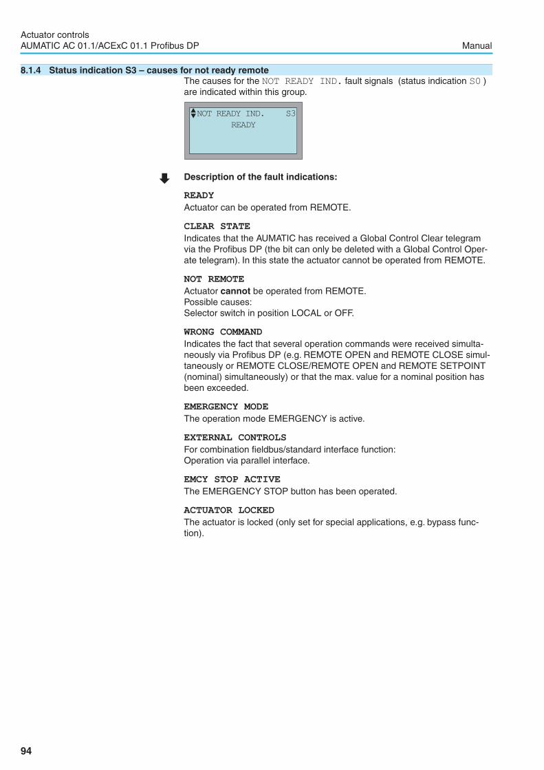
8.1.4 Status indication S3 – causes for not ready remoteThe causes for the NOT READY IND. fault signals (status indication S0 )are indicated within this group.
� Description of the fault indications:
READY
Actuator can be operated from REMOTE.
CLEAR STATE
Indicates that the AUMATIC has received a Global Control Clear telegramvia the Profibus DP (the bit can only be deleted with a Global Control Oper-ate telegram). In this state the actuator cannot be operated from REMOTE.
NOT REMOTE
Actuator cannot be operated from REMOTE.Possible causes:Selector switch in position LOCAL or OFF.
WRONG COMMAND
Indicates the fact that several operation commands were received simulta-neously via Profibus DP (e.g. REMOTE OPEN and REMOTE CLOSE simul-taneously or REMOTE CLOSE/REMOTE OPEN and REMOTE SETPOINT(nominal) simultaneously) or that the max. value for a nominal position hasbeen exceeded.
EMERGENCY MODE
The operation mode EMERGENCY is active.
EXTERNAL CONTROLS
For combination fieldbus/standard interface function:Operation via parallel interface.
EMCY STOP ACTIVE
The EMERGENCY STOP button has been operated.
ACTUATOR LOCKED
The actuator is locked (only set for special applications, e.g. bypass func-tion).
94
Actuator controlsAUMATIC AC 01.1/ACExC 01.1 Profibus DP Manual
�NOT READY IND. S3
READY

8.2 Diagnostics
Table of contents:8.2.1 Operating data logging8.2.2 Diagnostic indication (D) via the display
8.2.1 Operating data loggingThe operating data provides details e.g. about the running time, the numberof starts, number of torque faults etc.The analysis of this data provides valuable information regarding the optimi-zation of both actuator and valve. When using this information purposefully,actuator and valve will be carefully operated, e.g. through appropriateparameter setting.In case of fault, the logging of operating data makes a quick error diagnosticspossible.
Enable viewingThe OPERATIONAL DATA configuration must be set to VIEW ENABLED:
� Via the menu to parameter:MAIN MENU (M0)
CONFIGURATION (M4)
SPECIAL FUNCTIONS (M40)
OPERATIONAL DATA (M4012)
Default value: VIEW ENABLED
� Description of the parameter settings:
VIEW NOT ENABLED
The operational data is not indicated in the display
VIEW ENABLED
The operational data is indicated in the display
Viewing the operational data
� Via the menu to parameter:MAIN MENU (M0)
OPERATIONAL DATA (M2)
Various data is monitored by the AUMATIC and saved to a non-volatilememory (EEPROM). Two counters are provided, one of them is erasable.The recorded data can be read and deleted via the display. The access rightfor deletion is password-protected.
95
Actuator controlsManual AUMATIC AC 01.1/ACExC 01.1 Profibus DP
EDIT M4012
OPERATIONAL DATA
VIEW ENABLED
� :EDIT �:OK C:ESC
OPERATIONAL DATA M200
TOTAL MOTOR RUNTIME
MOTOR RUNTIME
TOTAL STARTS
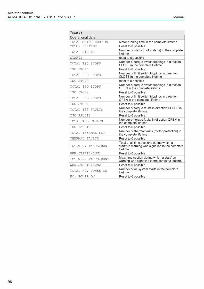
96
Actuator controlsAUMATIC AC 01.1/ACExC 01.1 Profibus DP Manual
Operational dataTOTAL MOTOR RUNTIME Motor running time in the complete lifetimeMOTOR RUNTIME Reset to 0 possible
TOTAL STARTSNumber of starts (motor starts) in the completelifetime
STARTS reset to 0 possible
TOTAL TSC STOPSNumber of torque switch trippings in directionCLOSE in the complete lifetime
TSC STOPS Reset to 0 possible
TOTAL LSC STOPSNumber of limit switch trippings in directionCLOSE in the complete lifetime
LSC STOPS reset to 0 possible
TOTAL TSO STOPSNumber of torque switch trippings in directionOPEN in the complete lifetime
TSO STOPS Reset to 0 possible
TOTAL LSO STOPSNumber of limit switch trippings in directionOPEN in the complete lifetime
LSO STOPS Reset to 0 possible
TOTAL TSC FAULTSNumber of torque faults in direction CLOSE inthe complete lifetime
TSC FAULTS Reset to 0 possible
TOTAL TSO FAULTSNumber of torque faults in direction OPEN inthe complete lifetime
TSO FAULTS Reset to 0 possible
TOTAL THERMAL FLT.Number of thermal faults (motor protection) inthe complete lifetime
THERMAL FAULTS Reset to 0 possible
TOT.WRN.STARTS/RUN1
Total of all time sections during which astart/run warning was signalled in the completelifetime.
WRN.STARTS/RUN1 Reset to 0 possible
TOT.WRN.STARTS/RUN2Max. time section during which a start/runwarning was signalled in the complete lifetime.
WRN.STARTS/RUN2 Reset to 0 possible
TOTAL NO. POWER ONNumber of all system starts in the completelifetime
NO. POWER ON Reset to 0 possible
Table 11
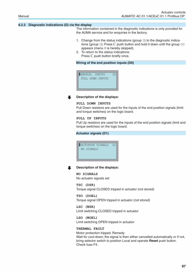
8.2.2 Diagnostic indications (D) via the displayThe information contained in the diagnostic indications is only provided forthe AUMA service and for enquiries in the factory.
1. Change from the status indications (group S) to the diagnostic indica-tions (group D): Press C push button and hold it down until the group D0appears (menu M is hereby skipped).
2. To return to the status indications:Press C push button briefly once.
Wiring of the end position inputs (D0)
� Description of the displays:
PULL DOWN INPUTS
Pull Down resistors are used for the inputs of the end position signals (limitand torque switches) on the logic board.
PULL UP INPUTS
Pull Up resistors are used for the inputs of the end position signals (limit andtorque switches) on the logic board.
Actuator signals (D1)
� Description of the displays:
NO SIGNALS
No actuator signals set
TSC (DSR)
Torque signal CLOSED tripped in actuator (not stored)
TSO (DOEL)
Torque signal OPEN tripped in actuator (not stored)
LSC (WSR)
Limit switching CLOSED tripped in actuator
LSO (WOEL)
Limit switching OPEN tripped in actuator
THERMAL FAULT
Motor protection tripped. Remedy:Wait for cool-down; the signal is then either cancelled automatically or if not,bring selector switch to position Local and operate Reset push button.Check fuse F4.
97
Actuator controlsManual AUMATIC AC 01.1/ACExC 01.1 Profibus DP
�ENDPOS. INPUTS D0
PULL DOWN INPUTS
�ACTUATOR SIGNALS D1
NO SIGNALS
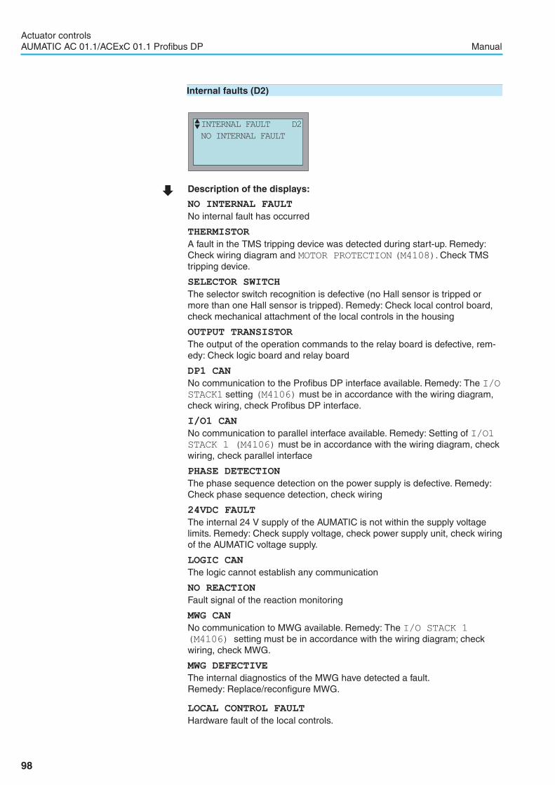
Internal faults (D2)
� Description of the displays:
NO INTERNAL FAULT
No internal fault has occurred
THERMISTOR
A fault in the TMS tripping device was detected during start-up. Remedy:Check wiring diagram and MOTOR PROTECTION (M4108). Check TMStripping device.
SELECTOR SWITCH
The selector switch recognition is defective (no Hall sensor is tripped ormore than one Hall sensor is tripped). Remedy: Check local control board,check mechanical attachment of the local controls in the housing
OUTPUT TRANSISTOR
The output of the operation commands to the relay board is defective, rem-edy: Check logic board and relay board
DP1 CAN
No communication to the Profibus DP interface available. Remedy: The I/OSTACK1 setting (M4106) must be in accordance with the wiring diagram,check wiring, check Profibus DP interface.
I/O1 CAN
No communication to parallel interface available. Remedy: Setting of I/O1STACK 1 (M4106) must be in accordance with the wiring diagram, checkwiring, check parallel interface
PHASE DETECTION
The phase sequence detection on the power supply is defective. Remedy:Check phase sequence detection, check wiring
24VDC FAULT
The internal 24 V supply of the AUMATIC is not within the supply voltagelimits. Remedy: Check supply voltage, check power supply unit, check wiringof the AUMATIC voltage supply.
LOGIC CAN
The logic cannot establish any communication
NO REACTION
Fault signal of the reaction monitoring
MWG CAN
No communication to MWG available. Remedy: The I/O STACK 1
(M4106) setting must be in accordance with the wiring diagram; checkwiring, check MWG.
MWG DEFECTIVE
The internal diagnostics of the MWG have detected a fault.Remedy: Replace/reconfigure MWG.
LOCAL CONTROL FAULT
Hardware fault of the local controls.
98
Actuator controlsAUMATIC AC 01.1/ACExC 01.1 Profibus DP Manual
�INTERNAL FAULT D2
NO INTERNAL FAULT

Internal warnings (D3)
� Description of the displays:
NO INTERNAL WARNING
No internal warnings have occurred
NO FACTORY PARAMS
No valid factory settings are available.
Configuration fault (D4)
� Description of the displays:
NO FAULT
AUMATIC has been correctly configured.
END POSITION INPUTS
The LIMIT/TORQUE-SWITCH parameter setting does not correspond tothe ENDPOS. INPUTS parameter configuration (can only be modified bythe AUMA service).
NO SWITCHING OFF
The LIMIT/TORQUE-SWITCH parameter setting does not correspond tothe CONTROL UNIT ) parameter configuration (can only be modified by theAUMA service).
Hardware version of the logic (D5)
� Description of the display:
LOGIC HRDWR. VER.
Display of hardware version of the logic
99
Actuator controlsManual AUMATIC AC 01.1/ACExC 01.1 Profibus DP
�INTERNAL WARNING D3
NO INTERNAL WARNING
�CONFIGURATION FAULT D4
NO FAULT
�LOGIC HRDWR. VER D5

Software version of the logic (D6)
� Description of the display:
LOGIC SFTWR. VER.
Display of software version of the logic
Potentiometer values (D7)
� Description of the display:
POT. VALUE
The voltage values are displayed here if a potentiometer is installed:in line 2 the value in end position CLOSED,in line 3 the current value andin line 4 the value in end position OPEN
RWG data (D8)
� Description of the display:
RWG VALUE
The current values are displayed here if an RWG is installed:in line 2 the value in end position CLOSED,in line 3 the current value andin line 4 the value in end position OPEN
100
Actuator controlsAUMATIC AC 01.1/ACExC 01.1 Profibus DP Manual
�POT. VALUE D7
�RWG VALUE D8
�LOGIC SFTWR. VER D6

MWG value (D9)
� Description of the display:
MWG VALUE
The current values are displayed here if an MWG is installed:in line 2 the value in end position CLOSED,in line 3 the current value andin line 4 the value in end position OPEN
MWG hardware version (DA)
� Description of the display:
MWG HRDWR.VER.
Hardware version of the MWG
MWG software version (DB)
� Description of the display:
MWG SFTWR.VER.
Software version of the MWG
MWG status (Dd)
� Description of the displays:
MWG OK
MWG is working, no faults.
HALLSENSOR ERROR
Remedy: Exchange MWG.
101
Actuator controlsManual AUMATIC AC 01.1/ACExC 01.1 Profibus DP
�MWG SFTWR.VER. DB
�MWG HRDWR.VER. DA
�MWG STATUS Dd
�MWG VALUE D9

E2PROM ERROR
Remedy: Exchange MWG.
NOT CALIBRATED
Remedy: Re-calibrate MWG (can only be performed in the factory).
NO POSITION REFEREN.
Remedy: Re-calibrate MWG (can only be performed in the factory).
TORQUE SYSTEM FAULT
Remedy: Exchange MWG.
NO ENDPOSITIONS
Remedy: Re-set limit end positions (can only be performed in the factory).
NO TORQUE LIMITS
Remedy: Re-set torque pivot points (can only be performed in the factory).
DP1 hardware version (DC)
� Description of the display:
DP1 HRDWR.VER.
Hardware version of the Profibus DP interface
DP1 software version (DD)
� Description of the display:
DP1 SFTWR.VER.
Software version of the Profibus DP interface
DP1 bus status (DE)
� Description of the displays:
BAUD SEARCH
The Profibus DP interface searches a baud rate. If no baud rate is found:connect DP cable, check, switch on DP master
BAUD CONTROL
The detected baud rate is monitored. The DP watchdog in the master is notactivated. Thus, the failure function is available
102
Actuator controlsAUMATIC AC 01.1/ACExC 01.1 Profibus DP Manual
�DP1 BUS STATUS DE
�DP1 SFTWR.VER. DD
�DP1 HRDWR.VER. DC
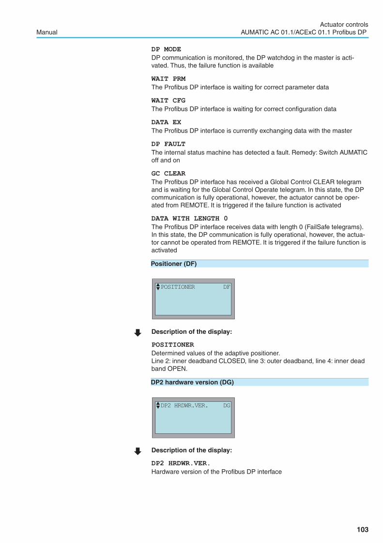
DP MODE
DP communication is monitored, the DP watchdog in the master is acti-vated. Thus, the failure function is available
WAIT PRM
The Profibus DP interface is waiting for correct parameter data
WAIT CFG
The Profibus DP interface is waiting for correct configuration data
DATA EX
The Profibus DP interface is currently exchanging data with the master
DP FAULT
The internal status machine has detected a fault. Remedy: Switch AUMATICoff and on
GC CLEAR
The Profibus DP interface has received a Global Control CLEAR telegramand is waiting for the Global Control Operate telegram. In this state, the DPcommunication is fully operational, however, the actuator cannot be oper-ated from REMOTE. It is triggered if the failure function is activated
DATA WITH LENGTH 0
The Profibus DP interface receives data with length 0 (FailSafe telegrams).In this state, the DP communication is fully operational, however, the actua-tor cannot be operated from REMOTE. It is triggered if the failure function isactivated
Positioner (DF)
� Description of the display:
POSITIONER
Determined values of the adaptive positioner.Line 2: inner deadband CLOSED, line 3: outer deadband, line 4: inner deadband OPEN.
DP2 hardware version (DG)
� Description of the display:
DP2 HRDWR.VER.
Hardware version of the Profibus DP interface
103
Actuator controlsManual AUMATIC AC 01.1/ACExC 01.1 Profibus DP
�DP2 HRDWR.VER. DG
�POSITIONER DF

DP2 software version (DH)
� Description of the display:
DP2 SFTWR.VER.
Software version of the Profibus DP interface
DP2 bus status (DI)
� Description of the displays:The displays are identical to the diagnostic displays of DP1 bus status (DE),refer to page 102)
E1 value (DJ)
� Description of the display:
E1 VALUE
Shows setpoint E1 in mA (only for standard I/O interface)
Internal faults 2 (DQ)
� Description of the displays:
RAM FAILURE
RAM of the logic defective.Remedy: Replace logic.
EEPROM FAILURE
EEprom of the logic defective. Remedy: Check logic, if necessary exchangeEEprom.
104
Actuator controlsAUMATIC AC 01.1/ACExC 01.1 Profibus DP Manual
�DP2 BUS STATUS DI
�E1 VALUE DJ
�INTERNAL FAULT 2 DQ
�DP2 SFTWR.VER. DH

Bluetooth hardware version (D14)
� Description of the display:
BT-OSS-HW-VERSI
Hardware version of the Bluetooth local controls
Bluetooth software version (D15)
� Description of the display:
BT-OSS-SW-VERSI
Software version of the Bluetooth local controls
105
Actuator controlsManual AUMATIC AC 01.1/ACExC 01.1 Profibus DP
�BT-OSS-SW-VERSI D15
�BT-OSS-HW-VERSI D14
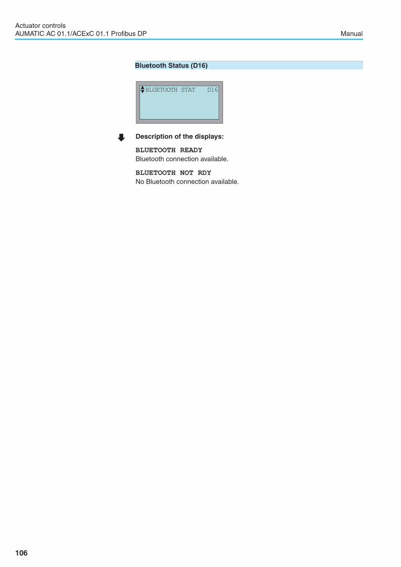
Bluetooth Status (D16)
� Description of the displays:
BLUETOOTH READY
Bluetooth connection available.
BLUETOOTH NOT RDY
No Bluetooth connection available.
106
Actuator controlsAUMATIC AC 01.1/ACExC 01.1 Profibus DP Manual
�BLUETOOTH STAT D16

8.3 Troubleshooting
8.3.1 Problems with position feedback/indication E2 (from actuator)� Check FEEDBACK E2 (M4101) parameter, page 31):
Value must correspond to the installed position transmitter.� Check I/O1 ANALOG OUT1 (M410A) parameter:
Value must correspond to wiring diagram.� Check I/O ANLOG OUT1 TYPE (M410A) parameter:
Value must correspond to desired feedback.� Check fieldbus configuration� Check diagnostic indications D7 or D8 (depending on the type of posi-
tion transmitter installed in the actuator):The value in the upper line is the raw value in the end position CLOSED,the value in the bottom line is the raw value in the end position OPENwhile the value in the middle line is the current position transmitter rawvalue (it must change evenly throughout the complete stroke when theoutput drive shaft is turning).
� For torque seating:Set limit end position as close as possible to torque switching off point
� Check galvanically isolated 24 V DC supply of the position feedback
8.3.2 Display hardly readable or illegible� Check AUMATIC 24 V voltage supply (e.g. when switching on, all LEDs
of the local controls must briefly light up, if necessary, check fuses).� Change LCD contrast (for green display only). For this, change LCD
CONTRAST(M011) parameter (the higher the value the darker thedisplay).
8.3.3 Actuator does not run� Check motor voltage supply.� Check AUMATIC 24 V voltage supply (e.g. when switching on, all LEDs
of the local controls must briefly light up, if necessary, check fuses).� Check fault signals (status indication S1 or diagnostic indication D2 ).
Actuator cannot be operated when fault signals have occurred.
8.3.4 Actuator does only operate from local� Check setting of I/O STACK 1 (M4106). The setting must corre-
spond to wiring diagram.� Check NOT READY IND. (status indication S3) indication.
8.3.5 Actuator is not switched off by limit seating in direction CLOSE or OPENThe actuator is set to torque seating.Set actuator to limit seating:� Set parameter CLOSED POSITION (page 45) to LIMIT.� Set parameter OPEN POSITION (page 45) to LIMIT.
107
Actuator controlsManual AUMATIC AC 01.1/ACExC 01.1 Profibus DP

IndexAAdaptive behaviour 55Alarm contact 29Analogue output 1feedback signals 32Analogue output 2feedback signals 34Analogue positionfeedback signal 33,34
BBlinker 21,30Bluetooth interface 12Bus address 77
CCollective fault signal 29COM-AC 12COM-AC (software) 8Combination fieldbus/standardinterface 83Commission number 7Contrast 14Control 7Corrective action 91
DDead band 56Dead time 57Delay time 43Derivative gain 64Diagnostics 95Display - indications 15
EElectronic name plate 17EMERGENCY behaviour 38,40EMERGENCY operation 38EMERGENCY position 40EMERGENCY STOP function 75End position tolerance 58External inputs for bus 80
FFailure behaviour 41,66Failure delay time 43Failure functions 84Failure operation 41,42,44Failure position 42Failure source 42,44Fault signal 25Faults 91Feedback signals 31Feedback signals via outputcontacts 27Functions of the AUMATIC 45
II/O stack 2 78,83Identification 7
Indication lights 19Indications 15Infra-red interface 12Input MODE 58Input range of process setpoint 69Input range process variable 69Intermediate positions 48Internet 7Intrusive 8Inverse operation 66
LLanguage change in the display 14LEDs 19Limit seating 45Limit switching 47Limitation of the travel 67Local controls 9Local controls enable function 73Logging of operating data 95Loss of the process setpoint 66
MMax. error variable (outer deadband) 57Max. permissible operation time 88MODE input 58Monitoring functions 84Motor protection 85Motor protection by-pass 40Multiport valve function 52
NName plate 7Non-Intrusive 8Non-Intrusive (version) 8Number of starts 86
OOFF times 72ON times 72Open-close duty
Open-close duty – modulatingduty selection 58
Operating time monitoring 88Operation 9Operation mode 35Operation mode EMERGENCY 38Operation mode FAILURE 41Operation mode LOCAL 36Operation mode OFF 35Operation mode REMOTE 37Operation modeSETPOINT MODE 55Output contacts 27Overrun (inner dead band) 56
PPassword change 13Password entry 11
Percent/per mil change-over 26Phase failure monitoring 90Position feedback signals 31Position transmitter 31Positioner 55Preset position 43Process controller 61Process representation input 22Process setpoint, internal 65Profibus DP interface 77Profibus DP-V1 services 79Proportional gain 63PTC thermistors 85Push-to-run operation 9,36,37
RRange of application 6Rate time 64Reaction monitoring 68,89Reaction of actuator 39,42Reset time 63Running indication 19,21,30Running time per hour 86Running time, max. permissible 87
SSafety instructions 5Self-retaining 9,36,37Setpoint E1
Input range 60Source 59
Short description 8Signals 22Signals via fieldbus 22Size 7Slave address 77Source for initiation 42,44Status indication 15Stepping mode 70Stepping range 71
TThermoswitches 85Torque by-pass 84Torque E6 32Torque feedback signal 33Torque indication 16Torque monitoring 84Torque seating 45Torque switching by-pass 40Type 7Type of seating 45
VValve position 15
WWarnings 91Wiring diagram (name plate) 7
108
Actuator controlsAUMATIC AC 01.1/ACExC 01.1 Profibus DP Manual

Parameter index and indications on the displayAADAPTIVE BEHAVIOUR 55
ALARM CONTACT 29
ANALOGUE VALUES DP 26
BBEHAVIOUR-LOSS OF E1 66
BLINKER 21,30
BY-PASS DURATION 84
BYTE 5.0 CONFIG. 23
BYTE 5.7 CONFIG. 25
BYTE 6.0 CONFIG. 23
BYTE 7.0 CONFIG. 23
BYTE 8.0 CONFIG. 23
BYTE ORDER PATTERN 22
CCHANGE PASSWORD 13
CLOSED POSITION 45,47
CLOSING 46
CLOSING DEADBAND 56
CONTROL LIMIT CLOSE 67
CONTROL LIMIT OPEN 67
DDEAD TIME 57
DELAY TIME 43
DERIVATIVE GAIN KD 64
DIAGNOSTIC INDICATIONS
D0 – END POS. INPUTS 97
D1 – ACTUATOR SIGNALS 97
D14 – BT-OSS-HW-VERSI 105
D15 – BT-OSS-SW-VERSI 105
D16 - BLUETOOTH STATUS 106
D2 – INTERNAL FAULTS 98
D3 – INTERNAL WARNINGS 99
D4 – CONFIGURATION FAULT99
D5 – LOGIC HRDWR.VER. 99
D6 – LOGIC SFTWR.VER. 100
D7 – POT. VALUE 100
D8 - RWG VALUE 100
D9 - MWG VALUE 101
DA - MWG HRDWR.VER. 101
DB - MWG SFTWR.VER. 101
DC - DP1 HRDWR.VER 102
DD - DP1 SFTWR.VER. 102
DD - MWG STATUS 101
DE - DP1 BUS STATUS 102
DF - POSITIONER 103
DG - DP2 HRDWR.VERS. 103
DH - DP2 SFTWR.VER. 104
DI - DP2 BUS STATUS 104
DJ - E1 VALUE 104
DQ – INTERNAL FAULTS 104
DIRECTION CLOSE 71
DIRECTION OPEN 71
DP1 ANLOG IN1 END 60
DP1 ANLOG IN1 START 60
DP1 ANLOG IN2 END 69
DP1 ANLOG IN2 START 69
DP-V1 SERVICES 79
EE4 MAX. REACTION 68
E4 MIN. REACTION 68
E4 REACTION TIME 68
EL. NAME PLATE 17
EMERG.SEL.SW.POS. 38
EMERGENCY BEHAVIOUR 39
EMERGENCY BY-PASS 40
EMERGENCY POSITION 39
ENABLE LOCAL MODE 73
END POSITION OPEN 45
EXTERNAL INPUTS BUS 80
FFAILURE ACTION 43
FAILURE BEHAVIOUR 41
FAILURE POSITION 42
FAILURE SOURCE 42
FEEDBACK E2 31
FULL CLOSE ADJUST 58
FULL OPEN ADJUST 58
II/O 1 37
I/O STACK 2 78
I/O1 ANALOG OUT1 32
I/O1 ANALOG OUT1 TYPE 33
I/O1 ANALOG OUT2 34
I/O1 ANALOG OUT2 TYPE 34
I/O1 ANLOG IN1 END 60
I/O1 ANLOG IN1 START 60
INTERMED. POSITION 48
INTERNAL SET POINT 65
INVERSE OPERATION
(PROCESS CONTROLLER) 66
LLANGUAGE 14
LCD CONTRAST 14
LED 1 (LEFT HAND) 20
LED 2 20
LED 3 20
LED 4 20
LED 5 (RIGHT HAND) 20
LOCAL CLIENT 12
MMAINTAINED LOCAL 36
MAINTAINED REMOTE 37
MAX. DUTY CYCLE 87
MAX. RUN TIME 88
MAX. STARTS/HOUR 87
MONITOR TRIGGERS 86,87,88
MOTOR PROTECTION 85
OOFF TIME CLOSE 72
OFF TIME OPEN 72
ON TIME CLOSE 72
ON TIME OPEN 72
OPEN POSITION 47
OPENING 46
OPENING DEADBAND 56
OPERATIONAL DATA 95
ORDER DATA 17
OUTER DEADBAND 57
OUTPUT CONTACT 1 27
OUTPUT CONTACT 2 27
OUTPUT CONTACT 3 27
OUTPUT CONTACT 4 27
OUTPUT CONTACT 5 27
PPID TYPE 65
POS NUMBER 54
POS. 1 49,53
POS. DIRECTRUNNING 52
POS.1 BEHAVIOUR 50
POS.1 CONTROL 50
POS.1 SELECTOR SW 49
POSITIONER 53
PRESET POSITION 40,43
PROCESS CONTROL PID 62
PRODUCT DATA 17
PROJECT DATA 17
PROPORT. GAIN KP 63
RRATE TIME TD 64
REACTION MONITORING 89
RESET TIME TI 63
SSEATING MODE 45
SERVICE DATA 17
SET LIMIT SWITCHES 47
SETPOINT E1 59
SLAVEADDRESS 77
START STEP CLOSE 71
START STEP OPEN 71
STEPPING MODE 70
STOP STEP CLOSE 71
STOP STEP OPEN 71
TTORQUE 46,84
TORQUE E6 32
TORQUE INDICATION 16
109
Actuator controlsManual AUMATIC AC 01.1/ACExC 01.1 Profibus DP

EuropeAUMA Riester GmbH & Co. KGPlant MüllheimDE-79373 MüllheimTel +49 7631 809 - 0Fax +49 7631 809 - [email protected]
Plant Ostfildern-NellingenDE-73747 OstfildernTel +49 711 34803 - 0Fax +49 711 34803 - [email protected]
Service-Center KölnDE-50858 KölnTel +49 2234 2037 - 9000Fax +49 2234 2037 - [email protected]
Service-Center MagdeburgDE-39167 NiederndodelebenTel +49 39204 759 - 0Fax +49 39204 759 - [email protected]
Service-Center BayernDE-85386 EchingTel +49 81 65 9017- 0Fax +49 81 65 9017- [email protected]
AUMA Armaturenantriebe GmbHAT-2512 TribuswinkelTel +43 2252 82540Fax +43 2252 [email protected]
AUMA (Schweiz) AGCH-8965 BerikonTel +41 566 400945Fax +41 566 [email protected]
AUMA Servopohony spol. s.r.o.CZ-250 01 Brandýs n.L.-St.BoleslavTel +420 326 396 993Fax +420 326 303 [email protected]
OY AUMATOR ABFI-02230 EspooTel +358 9 5840 22Fax +358 9 5840 [email protected]
AUMA France S.A.R.L.FR-95157 Taverny CedexTel +33 1 39327272Fax +33 1 [email protected]
AUMA ACTUATORS Ltd.GB- Clevedon North Somerset BS21 6QHTel +44 1275 871141Fax +44 1275 [email protected]
AUMA ITALIANA S.r.l. a socio unicoIT-20023 Cerro Maggiore (MI)Tel +39 0331 51351Fax +39 0331 [email protected]
AUMA BENELUX B.V.NL-2314 XT LeidenTel +31 71 581 40 40Fax +31 71 581 40 [email protected]
AUMA Polska Sp. z o.o.PL-41-310 Dabrowa GórniczaTel +48 32 261 56 68Fax +48 32 261 48 [email protected]
OOO Priwody AUMARU-141400 Moscow region for mail:124365 Moscow a/ya 11Tel +7 495 221 64 28Fax +7 495 221 64 [email protected]
ERICHS ARMATUR ABSE-20039 MalmöTel +46 40 311550Fax +46 40 [email protected]
GRØNBECH & SØNNER A/SDK-2450 København SVTel +45 33 26 63 00Fax +45 33 26 63 [email protected]
IBEROPLAN S.A.ES-28027 MadridTel +34 91 3717130Fax +34 91 [email protected]
D. G. Bellos & Co. O.E.GR-13671 Acharnai AthensTel +30 210 2409485Fax +30 210 [email protected]
SIGURD SØRUM A. S.NO-1300 SandvikaTel +47 67572600Fax +47 [email protected]
INDUSTRAPT-2710-297 SintraTel +351 2 1910 95 00Fax +351 2 1910 95 [email protected]
MEGA Endüstri Kontrol Sistemieri Tic. Ltd.Sti.TR-06810 AnkaraTel +90 312 217 32 88Fax +90 312 217 33 [email protected]
CTS Control Limited Liability CompanyUA-02099 KiyivTel +38 044 566-9971, -8427Fax +38 044 [email protected]
AfricaAUMA South Africa (Pty) Ltd.ZA-1560 SpringsTel +27 11 3632880Fax +27 11 [email protected]
A.T.E.C.EG- CairoTel +20 2 23599680 - 23590861Fax +20 2 [email protected]
AmericaAUMA ACTUATORS INC.US-PA 15317 CanonsburgTel +1 724-743-AUMA (2862)Fax +1 [email protected]
AUMA Automação do Brasil Ltda.BR-Sao PauloTel +55 11 [email protected]
AUMA Chile Representative OfficeCL-9500414 BuinTel +56 2 821 4108Fax +56 2 281 [email protected]
LOOP S. A.AR-C1140ABP Buenos AiresTel +54 11 4307 2141Fax +54 11 4307 [email protected]
TROY-ONTOR Inc.CA-L4N 5E9 Barrie OntarioTel +1 705 721-8246Fax +1 705 [email protected]
MAN Ferrostaal de Colombia Ltda.CO- Bogotá D.C.Tel +57 1 401 1300Fax +57 1 416 [email protected]
PROCONTIC Procesos y Control AutomáticoEC- QuitoTel +593 2 292 0431Fax +593 2 292 [email protected]
IESS de Mexico, S.A. de C.V.MX-C.P. 02900 Mexico D.F.Tel +52 55 55 56 1701Fax +52 55 55 56 [email protected]
Corsusa International S.A.C.PE- Miralflores - LimaTel +511444-1200 / 0044 / 2321Fax [email protected]
PASSCO Inc.PR-00936-4153 San JuanTel +18 09 78 77 20 87 85Fax +18 09 78 77 31 72 [email protected]
SuplibarcaVE- Maracaibo Estado, ZuliaTel +58 261 7 555 667Fax +58 261 7 532 [email protected]
AsiaAUMA Actuators (Tianjin) Co., Ltd.CN-300457 TianjinTel +86 22 6625 1310Fax +86 22 6625 [email protected]
AUMA (INDIA) PRIVATE LIMITEDIN-560 058 BangaloreTel +91 80 2839 4655Fax +91 80 2839 [email protected]
110
AUMA worldwide

AUMA JAPAN Co., Ltd.JP-210-0848 Kawasaki-ku, Kawasaki-shiKanagawaTel +91 80 2839 4655Fax +81 44 366 [email protected]
AUMA ACTUATORS (Singapore) Pte Ltd.SG-569551 SingaporeTel +65 6 4818750Fax +65 6 [email protected]
AUMA Actuators Middle East W.L.L.AE- 15268 Salmabad 704Tel +973 [email protected]
PERFECT CONTROLS Ltd.HK- Tsuen Wan, KowloonTel +852 2493 7726Fax +852 2416 [email protected]
DW Controls Co., Ltd.KR-153-803 Seoul KoreaTel +82 2 2113 1100Fax +82 2 2113 1088/[email protected]
Sunny Valves and Intertrade Corp. Ltd.TH-10120 Yannawa BangkokTel +66 2 2400656Fax +66 2 [email protected]/
Top Advance Enterprises Ltd.TW- Jhonghe City Taipei Hsien (235)Tel +886 2 2225 1718Fax +886 2 8228 [email protected]
AustraliaBARRON GJM Pty. Ltd.AU-NSW 1570 ArtarmonTel +61 294361088Fax +61 [email protected]
2009-01-22
111

Certificate Registration No.12 100/104 4269
AUMA Riester GmbH & Co. KGP.O.Box 1362D-79373 MüllheimTel +49 7631 809 - 0Fax+49 7631 809 - [email protected]
For detailed information on AUMA products refer to the Internet: www.auma.com
Y004.431/003/en/1.09