
AUGER BUCKET - Spartan Equipment€¦ · Never position the material by hand or with any tool when...
20
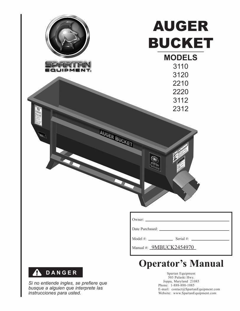
Si no entiende ingles, se prefiere que busque a alguien que interprete las instrucciones para usted. Owner: Date Purchased: Model #: Serial #: Manual #: 9MBUCK2454970 Operator’s Manual Spartan Equipment 503 Pulaski Hwy. Joppa, Maryland 21085 Phone: 1-888-888-1085 E-mail: [email protected] Website: www.SpartanEquipment.com DANGER AUGER BUCKET MODELS 3110 3120 2210 2220 3112 2312
Transcript of AUGER BUCKET - Spartan Equipment€¦ · Never position the material by hand or with any tool when...
Si no entiende ingles, se prefiere que busque a alguien que interprete las instrucciones para usted.
Owner:
Date Purchased:
Model #: Serial #:
Manual #: 9MBUCK2454970
Operator’s ManualSpartan Equipment503 Pulaski Hwy.
Joppa, Maryland 21085 Phone: 1-888-888-1085 E-mail: [email protected] Website: www.SpartanEquipment.com
D A N G E R
AUGERBUCKET
MODELS311031202210222031122312
Spartan EquipmentDear Owner/Operator,
Thank you for purchasing this Spartan Equipment Auger Bucket. We appreciate your business.
Your safety as an operator of our product is very important to us. Therefore, before you assemble, install, operate, maintain, service, remove, or move your Spartan Equipment Auger Bucket, read and understand this manual thoroughly. If there is anything you do not understand, immediately contact your dealer, or contact our factory direct.
Phone: 1-888-888-1085 E-mail: [email protected]
Your satisfaction in the performance and longevity of our product is also very important to us and can be prolonged by proper assembly, installation, operation, maintenance, service, and removal as instructed in this manual.
Thank you again for your business and for your trust in our product. Please feel free to contact us at any time for further assistance.
Sincerely,
Spartan Equipment
503 Pulaski Hwy. Joppa, MD 21085Phone: 1-888-888-1085
E-mail: [email protected]: www.SpartanEquipment.com
This SAFETY ALERT symbol identifies important safety messages. Carefully read each safety message that follows. Failure to understand and obey a safety message,
or recognize a safety hazard, could result in injury or death to you or others around you. The operator is ultimately responsible for the safety of himself, as well as others, in the operating area of the Auger Bucket.
3
PageLetter to the Owner/Operator . . . . . . . . . . . . . . . . . . . . . . . . . . . . . . . . . . . . . . . . . . . . 2 Foreword . . . . . . . . . . . . . . . . . . . . . . . . . . . . . . . . . . . . . . . . . . . . . . . . . . . . . . . . . . . . 3Symbols . . . . . . . . . . . . . . . . . . . . . . . . . . . . . . . . . . . . . . . . . . . . . . . . . . . . . . . . . . . . . 3Safety . . . . . . . . . . . . . . . . . . . . . . . . . . . . . . . . . . . . . . . . . . . . . . . . . . . . . . . . . . . . . . . 4Specifications. . . . . . . . . . . . . . . . . . . . . . . . . . . . . . . . . . . . . . . . . . . . . . . . . . . . . . . . . 6Hydraulic Requirements . . . . . . . . . . . . . . . . . . . . . . . . . . . . . . . . . . . . . . . . . . . . . . . . 7Assembly & Installation . . . . . . . . . . . . . . . . . . . . . . . . . . . . . . . . . . . . . . . . . . . . . . . . 8Operation . . . . . . . . . . . . . . . . . . . . . . . . . . . . . . . . . . . . . . . . . . . . . . . . . . . . . . . . . . . . 10Clean Up . . . . . . . . . . . . . . . . . . . . . . . . . . . . . . . . . . . . . . . . . . . . . . . . . . . . . . . . . . . . 12Removal & Storage . . . . . . . . . . . . . . . . . . . . . . . . . . . . . . . . . . . . . . . . . . . . . . . . . . . . 13Troubleshooting . . . . . . . . . . . . . . . . . . . . . . . . . . . . . . . . . . . . . . . . . . . . . . . . . . . . . . . 14Maintenance. . . . . . . . . . . . . . . . . . . . . . . . . . . . . . . . . . . . . . . . . . . . . . . . . . . . . . . . . . 15Service . . . . . . . . . . . . . . . . . . . . . . . . . . . . . . . . . . . . . . . . . . . . . . . . . . . . . . . . . . . . . . 15Parts . . . . . . . . . . . . . . . . . . . . . . . . . . . . . . . . . . . . . . . . . . . . . . . . . . . . . . . . . . . . . . . . 17Options. . . . . . . . . . . . . . . . . . . . . . . . . . . . . . . . . . . . . . . . . . . . . . . . . . . . . . . . . . . . . . 18Decals & Safety Signs . . . . . . . . . . . . . . . . . . . . . . . . . . . . . . . . . . . . . . . . . . . . . . . . . . 19Warranty. . . . . . . . . . . . . . . . . . . . . . . . . . . . . . . . . . . . . . . . . . . . . . . . . . . . . . Back Cover
Please read this manual thoroughly!Before you assemble, install, operate, maintain, service, remove, or move your Spartan Equipment Auger Bucket, read this manual thoroughly. If there is anything you do not understand, immediately contact your dealer, or call our factory direct at 1-888-888-1085. Powered equipment can be dangerous if not assembled, installed, operated, maintained, serviced, removed, or moved properly.
Warranty RegistrationTo activate your warranty coverage and to provide you with efficient customer service, please fill out your WARRANTY REGISTRATION FORM. This form is included in your unit’s paperwork package. If you did not complete a WARRANTY REGISTRATION FORM or did not receive one, please call Spartan Equipment. Your satisfaction with our product and your safety as a user of our product are both very important to us.
Immediate hazard! Failure to understand and obey this warning is likely to result in personal injury or death.
NOTE
This is important information for proper use of this equipment. Failure to comply may lead to premature equipment failure.
Failure to follow these instructions may cause damage to the implement or the vehicle, or minor personal injury.
Failure to follow these instructions may result in personal injury or death.
Symbol Meaning
W A R N I N G
D A N G E R
C A U T I O N
Foreword
Symbols
Table of Contents
D A N G E RImproper operation of this Auger Bucket can cause serious personal injury or death. Operation of this Auger Bucket should only be done by a competent adult acting in compliance with the Operator's Manual. Since Auger Bucket operations are beyond our control, we disclaim all liability for any damages, injuries or death which may result.
4
Working with unfamiliar equipment can lead to careless injuries. Read and understand this manual and the manual for your vehicle before assembling, installing, operating, maintaining, servicing, removing, or moving this Auger Bucket. If there is anything in this manual you do not understand, contact your dealer or Spartan Equipment. The safe use of this attachment is strictly up to you, the operator. If this attachment is used, loaned, or rented by any other person, it is the owner's responsibility to make certain that the operator prior to operating:
• Reads and understands the Operator's Manuals • Is instructed in safe and proper use
• The Auger Bucket is designed to be operated from the vehicle seat. Keep bystanders away from the work area. Do not operate with another person in contact with any part of the Auger Bucket.
• All operators of this attachment must read and understand this entire manual, paying particular attention to safety messages and operation instructions, prior to assembling, installing, operating, maintaining, servicing, removing, or moving the Auger Bucket.
• Please remember it is also important that you read, understand, and follow the safety signs on the attachment. Clean or replace all safety signs if they cannot be clearly read and understood. They are there for your safety as well as the safety of others. Spartan Equipment will furnish new safety signs upon request at no charge.
• All things with moving parts are potentially hazardous. There is no substitute for a cautious, safe- minded operator who recognizes potential hazards and follows reasonable safety practices.
• Personal protection equipment including hard hat, safety glasses, safety shoes, and gloves are recommended during assembly, installation, operation, maintenance, service, removal, or movement of attachment.
• When the use of hand tools is required to perform any part of assembly, installation, operation, maintenance, or service of the attachment, be sure the tools used are designed and recommended by the tool manufacturer for that specific task.
• Never check pressurized system for leaks with your bare hand. Wear proper hand and eye protection and use wood or cardboard when searching for suspected leaks. Oil escaping from pinhole leaks under pressure can penetrate skin and create a serious medical emergency. If any fluid is injected into the skin, gangrene, blood poisoning, even death may result. Obtain medical attention immediately.
• Always use two people to handle heavy, unwieldy components during assembly, installation, maintenance, service, removal, or movement of the Auger Bucket.
• Never place any part of your body where it would be in danger if movement should occur during assembly, installation, operation, maintenance, service, removal, or movement of the Auger Bucket.
• Only properly trained people should operate this equipment. Do not allow anyone who has not read this entire manual and understood the safety rules, safety signs, and operation instructions to use this attachment.
• Never allow children to operate or be around the Auger Bucket.
• Do not allow riders on the equipment at any time. There is no safe place for any riders.
• Never use alcoholic beverages or drugs which can hinder alertness or coordination while operating this equipment. Consult your doctor about operating this equipment while taking prescription medications.
W A R N I N GSafety
• Before you operate the attachment, check over pins and connections to be sure all are securely in place. Make sure the Auger Bucket is securely latched to the skid-steer.
• Keep hands, feet, hair, jewelry, and clothing away from all moving and/or rotating parts.
• Never place yourself between the vehicle and the attachment.
• Never allow anyone under the attachment at any time.
• Never reach into discharge end of auger.
• Keep clear of auger while in operation. Never position the material by hand or with any tool when the auger is rotating.
• Do not exceed the vehicle’s rated operating load. Use sufficient counterweights. Move the vehicle slowly when the attachment is raised.
• Carry the load low. A heavy load can cause instability of the vehicle. Use extreme care during travel. Slow down on turns and watch out for bumps. Use all safety devices, including a seat belt, as recommended in the vehicle operator’s manual.
• Do not operate the Auger Bucket on steep hillsides. When operating the Auger Bucket on uneven or hilly terrain, position the vehicle with the attachment uphill. With the attachment downhill, the vehicle could tip when attempting to raise the Auger Bucket. Consult your vehicle operator’s manual for maximum incline allowable.
• Always shut off the vehicle engine and remove the key before dismounting the vehicle, adjusting the attachment, or servicing the Auger Bucket. Never leave equipment unattended with the vehicle running.
• Never attempt repairs or adjustments while the equipment is in operation.
• Before disconnecting hydraulic lines or fittings be sure to relieve all pressure by cycling all hydraulic controls after shutdown. Remember hydraulic systems are under pressure whenever the engine is running and may hold pressure after shutdown.
• Always use care when operating the Auger Bucket. Most accidents occur because of neglect or carelessness.
Safety is a primary concern in the design, manufacture, sale, and use of Auger Buckets. Spartan Equipment confirms to you, our customer, our concern for safety.
5
Safety
(continued)
6
Specifications
• Mix, transport, and dispense concrete (up to 1” slump), sand, washed gravel (3/4” max.), wildlife feed, asphalt, agricultural grains, etc.
• 1/2 yard capacity; 3/4 yard capacity capable with optional hopper extension
• Accurate and controlled discharge – 1/2 yard in 50 seconds
• Horizontal steel auger with orbital motor drive
• Replaceable protective rubber flighting prevents binding of coarse material.
• Universal skid-steer attachment
• Quick attach frame on either side allows right- or left-hand discharge.
• Self loading from loose piles
• 7’ hose kit with flat face couplers included.
• 2 multi-linked chutes (24” & 36” long) included.
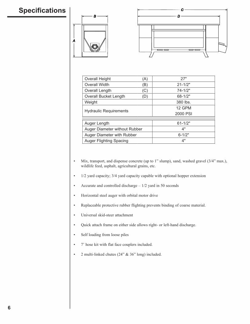
Overall Height (A) 27"Overall Width (B) 21-1/2"Overall Length (C) 74-1/2"Overall Bucket Length (D) 68-1/2"Weight 380 lbs.
Hydraulic Requirements12 GPM2000 PSI
Auger Length 61-1/2"Auger Diameter without Rubber 4"Auger Diameter with Rubber 6-1/2"Auger Flighting Spacing 4"
Filtration Requirements:
• A filter of, at least, 25 micron filtration is required. A filter capable of 10 micron filtration is preferred. The majority of paper type filters are 25 microns or better.
• A low pressure type filter can be installed in the return line from the control valves to the sump. A low pressure type filter can, also, be installed in the sump or pump intake line, but must be sized large enough to avoid starving the pump.
• A high pressure type filter can be used between the pump and the control valves.
• If the source of the hydraulic power does not have a filter, it will be necessary to install one at some point in the system so, at least, part of the hydraulic oil is being filtered whenever the system is operating. After a filter is installed and before attaching the Auger Bucket, the entire hydraulic system should be drained, filled with new oil, and operated for 30 minutes or until the system is warm. During this run time, operate all valves, cylinders, and hydraulic motors on the attachment.
Pressure and Flow Requirements:
• The Auger Bucket is designed to operate at 12 GPM and 2000 PSI.
Valve Requirements:
• The hydraulic system used to power the Auger Bucket should be equipped with a four- way valve large enough to carry full pump outlet without restricting flow and causing oil heating.
• The four-way valve requires a relief valve which will open and relieve extreme pressures between the Auger Bucket and control valve, even when the control valve is in a neutral position. This feature can be obtained by connecting two external relief valves between the main lines running from the control valve to the Auger Bucket in such a way that high pressure in either line will be relieved to the other line.
Hydraulic Fluid Selection Requirements:
• Premium grade petroleum based fluids will provide the best performance.
• Fluids that contain anti-wear agents, rust inhibitors, anti-foaming agents, and oxidation inhibitors are recommended.
• The viscosity of the fluid should never fall below 70 SUS (13 cST). The best viscosity range of the Auger Bucket is 100-200 SUS (20-43 cST).
NOTE The life of the hydraulic motor is almost entirely dependent upon cleanliness of the oil. Instructions in your vehicle operator’s manual regarding filter and oil changes should be carefully followed. Even small amounts of dirt in the hydraulic oil can cause premature motor failure that is not covered by warranty.
HydraulicRequirements
7
8
Assembly & Installation
Prepare the VehicleRead and understand the manual for your vehicle before assembling or installing the Auger Bucket. The skid-steer must be equipped with a universal quick attach hitch and auxiliary hydraulics. The use of the Auger Bucket may require the addition of counterweights to ensure the combined weight of the bucket and the material does not exceed the rated capacity of your vehicle.
Select the Right Auger BucketMIXING AUGER BUCKET• The mixing auger should be used anytime you are mixing your own material. Turn the auger in reverse for mixing and then forward for discharge. This auger has the wear rubber reversed for the first half of the auger (motor end). For added durability, this auger also has 40% more hardware than a discharge auger.
DISCHARGE AUGER BUCKET• The discharge auger should be used for dispensing material(s). The rubber flights have wear rubber on the discharge side.
STEP 1: Remove the chutes and hydraulic hoses from inside the Auger Bucket.
STEP 2: Remove the dust plugs from the hydraulic motor ports.
STEP 3: Locate the hydraulic fittings from the chute box, and install them into the motor.
STEP 4: Tighten the fittings into the motor, and install the hydraulic hoses provided.
STEP 5: Install the Auger Bucket by following your vehicle operator’s manual for installing an attachment. Be sure to securely latch the Auger Bucket to the skid-steer.
STEP 6: Use the quick couplers to connect the hydraulic hoses to the vehicle’s auxiliary hydraulics.
Make sure the Auger Bucket is securely latched to the skid-steer. Failure to do so could result in separation of the attachment from the skid-steer.
W A R N I N G
All hoses and fittings used to connect the Auger Bucket should be thoroughly cleaned before use. Care should be taken to see that no thread sealer or metal chips are forced to the inside of the joints when connections are being tightened.
NOTE
W A R N I N GPersonal protection equipment including hard hat, safety glasses, safety shoes, and gloves are recommended during assembly, installation, operation, maintenance, service, removal, or movement of the Auger Bucket.
D A N G E RDo not exceed the vehicle's rated operating load.If necessary, use sufficient counterweights.
Here is an easy formula for calculating weight: 1/2 yard bucket & material = empty bucket weight (380 lbs.) + 2,000 lbs. 3/4 yard bucket & material = empty bucket weight (380 lbs.) + 3,000 lbs.
NOTE
C A U T I O NDo not use the discharge auger for mixing. Running thisauger in the reverse direction for mixing will result in extreme premature wear of the rubber flighting.
9
STEP 7: Activate the vehicle’s auxiliary hydraulics to ensure the auger rotates toward the discharge end.
STEP 8: Check the hydraulic system for leaks.
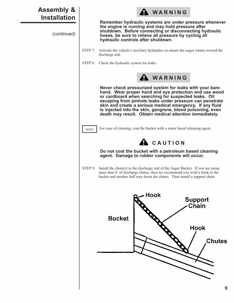
STEP 9: Install the chute(s) to the discharge end of the Auger Bucket. If you are using more than 8’ of discharge chutes, then we recommend you weld a hook to the bucket and another half way down the chutes. Then install a support chain.
Never check pressurized system for leaks with your bare hand. Wear proper hand and eye protection and use wood or cardboard when searching for suspected leaks. Oil escaping from pinhole leaks under pressure can penetrate skin and create a serious medical emergency. If any fluid is injected into the skin, gangrene, blood poisoning, even death may result. Obtain medical attention immediately.
Remember hydraulic systems are under pressure whenever the engine is running and may hold pressure after shutdown. Before connecting or disconnecting hydraulic hoses, be sure to relieve all pressure by cycling all hydraulic controls after shutdown.
W A R N I N G
For ease of cleaning, coat the bucket with a water based releasing agent.NOTE
C A U T I O NDo not coat the bucket with a petroleum based cleaning agent. Damage to rubber components will occur.
W A R N I N G
Assembly & Installation
(continued)
10
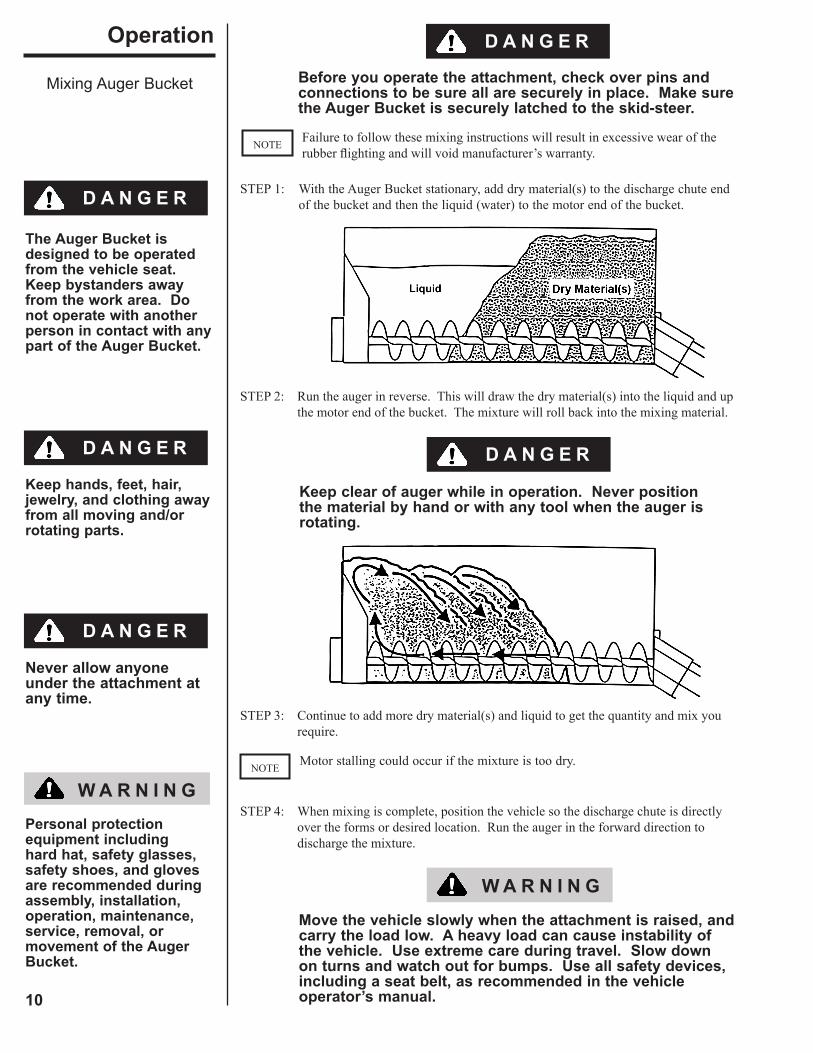
STEP 1: With the Auger Bucket stationary, add dry material(s) to the discharge chute end of the bucket and then the liquid (water) to the motor end of the bucket.
STEP 2: Run the auger in reverse. This will draw the dry material(s) into the liquid and up the motor end of the bucket. The mixture will roll back into the mixing material.
STEP 3: Continue to add more dry material(s) and liquid to get the quantity and mix you require.
STEP 4: When mixing is complete, position the vehicle so the discharge chute is directly over the forms or desired location. Run the auger in the forward direction to discharge the mixture.
Motor stalling could occur if the mixture is too dry.NOTE
Before you operate the attachment, check over pins and connections to be sure all are securely in place. Make sure the Auger Bucket is securely latched to the skid-steer.
Operation
Mixing Auger Bucket
Failure to follow these mixing instructions will result in excessive wear of the rubber flighting and will void manufacturer’s warranty.
NOTE
D A N G E R
Keep clear of auger while in operation. Never position the material by hand or with any tool when the auger is rotating.
Move the vehicle slowly when the attachment is raised, and carry the load low. A heavy load can cause instability of the vehicle. Use extreme care during travel. Slow down on turns and watch out for bumps. Use all safety devices, including a seat belt, as recommended in the vehicle operator’s manual.
W A R N I N G
Keep hands, feet, hair, jewelry, and clothing away from all moving and/or rotating parts.
D A N G E R
The Auger Bucket is designed to be operated from the vehicle seat. Keep bystanders away from the work area. Do not operate with another person in contact with any part of the Auger Bucket.
D A N G E R
W A R N I N GPersonal protection equipment including hard hat, safety glasses, safety shoes, and gloves are recommended during assembly, installation, operation, maintenance, service, removal, or movement of the Auger Bucket.
D A N G E R
Never allow anyone under the attachment at any time.
D A N G E R
11
STEP 1: With the Auger Bucket stationary, add material(s) to the bucket.
STEP 2: Position the vehicle so the discharge chute is directly over the desired location. Run the auger in the forward direction to discharge the material(s).
Operation
Discharging Auger Bucket Before you operate the attachment, check over pins and connections to be sure all are securely in place. Make sure the Auger Bucket is securely latched to the skid-steer.
Do not attempt to dig with the Auger Bucket. If the optional Scraper Blade is installed, then scoop from loose piles only.
NOTE
Keep clear of auger while in operation. Never position the material by hand or with any tool when the auger is rotating.
Move the vehicle slowly when the attachment is raised, and carry the load low. A heavy load can cause instability of the vehicle. Use extreme care during travel. Slow down on turns and watch out for bumps. Use all safety devices, including a seat belt, as recommended in the vehicle operator’s manual.
W A R N I N G
The Auger Bucket is designed to be operated from the vehicle seat. Keep bystanders away from the work area. Do not operate with another person in contact with any part of the Auger Bucket.
D A N G E R
D A N G E R
D A N G E R
Keep hands, feet, hair, jewelry, and clothing away from all moving and/or rotating parts.
D A N G E R
W A R N I N GPersonal protection equipment including hard hat, safety glasses, safety shoes, and gloves are recommended during assembly, installation, operation, maintenance, service, removal, or movement of the Auger Bucket.
Never allow anyone under the attachment at any time.
D A N G E R
12
STEP 1: Run the Auger Bucket until all of the material is removed from the bucket.
STEP 2: The operator should remain in the vehicle seat and run the auger in reverse. A second person, standing a safe distance away from the Auger Bucket, should use a hose to add water to the discharge end of the bucket.
STEP 3: After most of the material has been cleaned from the bucket, raise the bucket and tilt it forward. This will allow the second person, standing a safe distance away from the Auger Bucket, to use the hose to rinse out any remaining material.
STEP 4: Level the Auger Bucket, and lower it to the ground.
STEP 5: Shut off the vehicle engine, lower the arms, relieve all hydraulic pressure (by activating the vehicle controls), and remove the vehicle key before leaving the vehicle seat.
STEP 6: Disconnect the hydraulic hoses from the vehicle’s auxiliary hydraulics.
STEP 7: Remove the cotter pin, and lift the splash shield at the discharge end of the bucket. Clean it with water. Make sure there is not any material between the auger and the discharge casing.
STEP 8: Replace the splash shield, and secure it with the cotter pin.
STEP 9: Coat the bucket with a water based releasing agent. Do not allow concrete to dry in the bucket or water to freeze in the bucket. This will cause damage to the rubber flighting and damage the bucket itself.
Keep clear of auger while in operation. Never position the material by hand or with any tool when the auger is rotating.
Before disconnecting hydraulic lines or fittings be sure to relieve all pressure by cycling all hydraulic controls after shutdown. Remember hydraulic systems are under pressure whenever the engine is running and may hold pressure after shutdown.
W A R N I N G
Keep hands, feet, hair, jewelry, and clothing away from all moving and/or rotating parts.
D A N G E R
Never place yourself between the vehicle and the attachment.
D A N G E R
Never allow anyone under the attachment at any time.
D A N G E R
Clean Up
D A N G E R
Never reach into discharge end of auger.
D A N G E R
W A R N I N GPersonal protection equipment including hard hat, safety glasses, safety shoes, and gloves are recommended during assembly, installation, operation, maintenance, service, removal, or movement of the Auger Bucket.
13
Before storage, the Auger Bucket should be thoroughly cleaned per the instructions in the Clean Up section. Always store the Auger Bucket in a dry location. Do not allow concrete to dry in the bucket or water to freeze in the bucket. This will cause damage to the rubber flighting and damage the bucket itself.
STEP 1: Lower the Auger Bucket onto a flat, level surface.
STEP 2: Shut off the vehicle engine, lower the arms, relieve all hydraulic pressure (by activating the vehicle controls), and remove the vehicle key before leaving the vehicle seat.
STEP 3: Disconnect the hydraulic hoses from the vehicle’s auxiliary hydraulics.
STEP 4: Follow your vehicle operator’s manual for removing an attachment.
STEP 5: Coat the bucket with a water based releasing agent.
Removal & Storage
Before disconnecting hydraulic lines or fittings be sure to relieve all pressure by cycling all hydraulic controls after shutdown. Remember hydraulic systems are under pressure whenever the engine is running and may hold pressure after shutdown.
W A R N I N G
Connect quick couplers together to prevent contaminants from entering the bucket hydraulic system.
NOTE
C A U T I O NDo not coat the bucket with a petroleum based cleaning agent. Damage to rubber components will occur.
W A R N I N GPersonal protection equipment including hard hat, safety glasses, safety shoes, and gloves are recommended during assembly, installation, operation, maintenance, service, removal, or movement of the Auger Bucket.
Never allow anyone under the attachment at any time.
D A N G E R
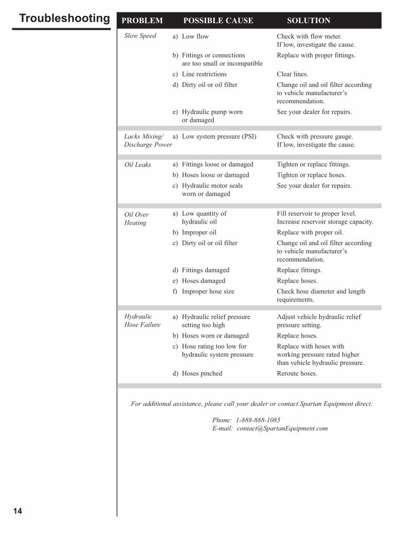
Lacks Mixing/ Discharge Power
a) Low flow Check with flow meter. If low, investigate the cause.
b) Fittings or connections Replace with proper fittings. are too small or incompatible c) Line restrictions Clear lines. d) Dirty oil or oil filter Change oil and oil filter according to vehicle manufacturer’s recommendation. e) Hydraulic pump worn See your dealer for repairs. or damaged
a) Low system pressure (PSI) Check with pressure gauge. If low, investigate the cause.
a) Fittings loose or damaged Tighten or replace fittings. b) Hoses loose or damaged Tighten or replace hoses.
c) Hydraulic motor seals See your dealer for repairs. worn or damaged
a) Low quantity of Fill reservoir to proper level. hydraulic oil Increase reservoir storage capacity. b) Improper oil Replace with proper oil.
c) Dirty oil or oil filter Change oil and oil filter according to vehicle manufacturer’s recommendation. d) Fittings damaged Replace fittings. e) Hoses damaged Replace hoses. f) Improper hose size Check hose diameter and length requirements.
a) Hydraulic relief pressure Adjust vehicle hydraulic relief setting too high pressure setting. b) Hoses worn or damaged Replace hoses.
c) Hose rating too low for Replace with hoses with hydraulic system pressure working pressure rated higher than vehicle hydraulic pressure. d) Hoses pinched Reroute hoses.
For additional assistance, please call your dealer or contact Spartan Equipment direct:
Phone: 1-888-888-1085 E-mail: [email protected]
PROBLEM POSSIBLE CAUSE SOLUTIONTroubleshootingSlow Speed
Oil Leaks
Oil OverHeating
Hydraulic Hose Failure
14
The Auger Bucket is practically maintenance free. There is only one grease zerk used to lubricate the motor seal. The zerk is located in the motor mounting plate. Grease the motor seal every 40 hours.
Thoroughly clean the Auger Bucket after each use, and apply a water based, non-corrosive releasing agent. Do not allow concrete to dry in the bucket or water to freeze in the bucket. This will cause damage to the rubber flighting and damage the bucket itself.
Rubber flighting disc replacement should be done only when performance has been reduced or material leaks out of the discharge end when the auger is not rotating. It is not necessary to replace all of the rubber flights at once. Replace only the flights that have extensive wear (usually the ones at the discharge end of the auger).
STEP 1: Lower the Auger Bucket onto a flat, level surface.
STEP 2: Shut off the vehicle engine, lower the arms, relieve all hydraulic pressure (by activating the vehicle controls), and remove the vehicle key before leaving the vehicle seat.
STEP 3: Disconnect the hydraulic hoses from the vehicle’s auxiliary hydraulics.
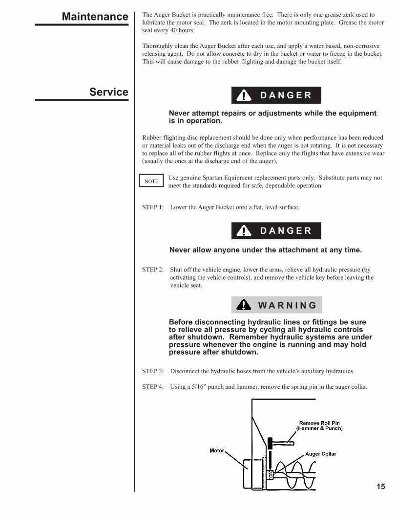
STEP 4: Using a 5/16” punch and hammer, remove the spring pin in the auger collar.
Maintenance
Service
Never attempt repairs or adjustments while the equipment is in operation.
Never allow anyone under the attachment at any time.
Before disconnecting hydraulic lines or fittings be sure to relieve all pressure by cycling all hydraulic controls after shutdown. Remember hydraulic systems are under pressure whenever the engine is running and may hold pressure after shutdown.
W A R N I N G
D A N G E R
D A N G E R
15
Use genuine Spartan Equipment replacement parts only. Substitute parts may not meet the standards required for safe, dependable operation.
NOTE
16
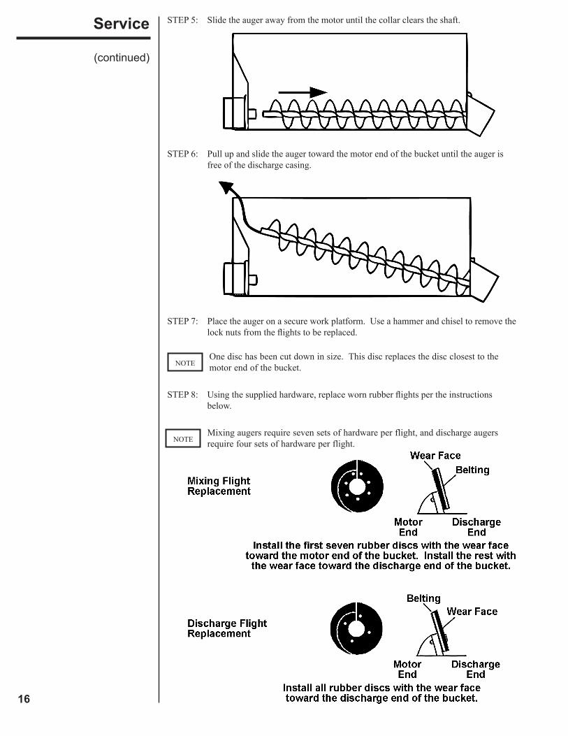
STEP 5: Slide the auger away from the motor until the collar clears the shaft.
STEP 6: Pull up and slide the auger toward the motor end of the bucket until the auger is free of the discharge casing.
STEP 7: Place the auger on a secure work platform. Use a hammer and chisel to remove the lock nuts from the flights to be replaced.
STEP 8: Using the supplied hardware, replace worn rubber flights per the instructions below.
Service
(continued)
Mixing augers require seven sets of hardware per flight, and discharge augers require four sets of hardware per flight.NOTE
One disc has been cut down in size. This disc replaces the disc closest to the motor end of the bucket.NOTE
17
= Safety Sign Location
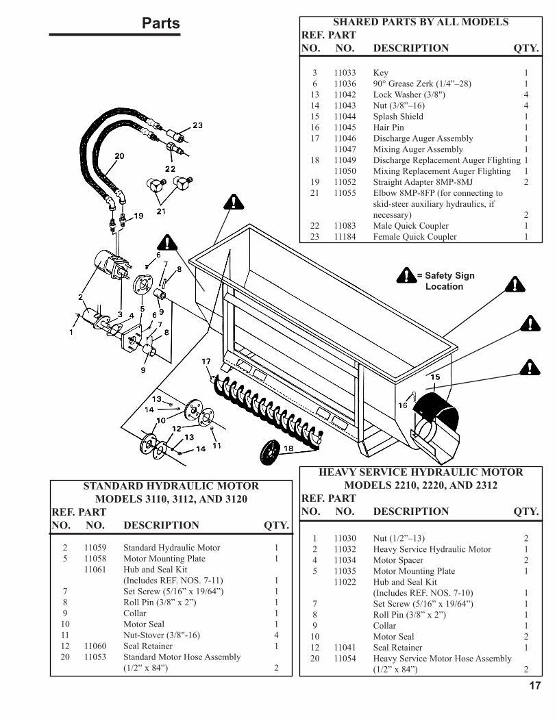
Parts
STANDARD HYDRAULIC MOTORMODELS 3110, 3112, AND 3120
REF. PART NO. NO. DESCRIPTION QTY.
2 11059 Standard Hydraulic Motor 1 5 11058 Motor Mounting Plate 1 11061 Hub and Seal Kit (Includes REF. NOS. 7-11) 1 7 Set Screw (5/16” x 19/64”) 1 8 Roll Pin (3/8” x 2”) 1 9 Collar 1 10 Motor Seal 1 11 Nut-Stover (3/8"-16) 4 12 11060 Seal Retainer 1 20 11053 Standard Motor Hose Assembly (1/2” x 84”) 2
HEAVY SERVICE HYDRAULIC MOTOR MODELS 2210, 2220, AND 2312
REF. PART NO. NO. DESCRIPTION QTY.
1 11030 Nut (1/2”–13) 2 2 11032 Heavy Service Hydraulic Motor 1 4 11034 Motor Spacer 2 5 11035 Motor Mounting Plate 1 11022 Hub and Seal Kit (Includes REF. NOS. 7-10) 1 7 Set Screw (5/16” x 19/64”) 1 8 Roll Pin (3/8” x 2”) 1 9 Collar 1 10 Motor Seal 2 12 11041 Seal Retainer 1 20 11054 Heavy Service Motor Hose Assembly (1/2” x 84”) 2
SHARED PARTS BY ALL MODELSREF. PART NO. NO. DESCRIPTION QTY.
3 11033 Key 1 6 11036 90° Grease Zerk (1/4”–28) 1 13 11042 Lock Washer (3/8") 4 14 11043 Nut (3/8”–16) 4 15 11044 Splash Shield 1 16 11045 Hair Pin 1 17 11046 Discharge Auger Assembly 1 11047 Mixing Auger Assembly 1 18 11049 Discharge Replacement Auger Flighting 1 11050 Mixing Replacement Auger Flighting 1 19 11052 Straight Adapter 8MP-8MJ 2 21 11055 Elbow 8MP-8FP (for connecting to skid-steer auxiliary hydraulics, if necessary) 2 22 11083 Male Quick Coupler 1 23 11184 Female Quick Coupler 1
18
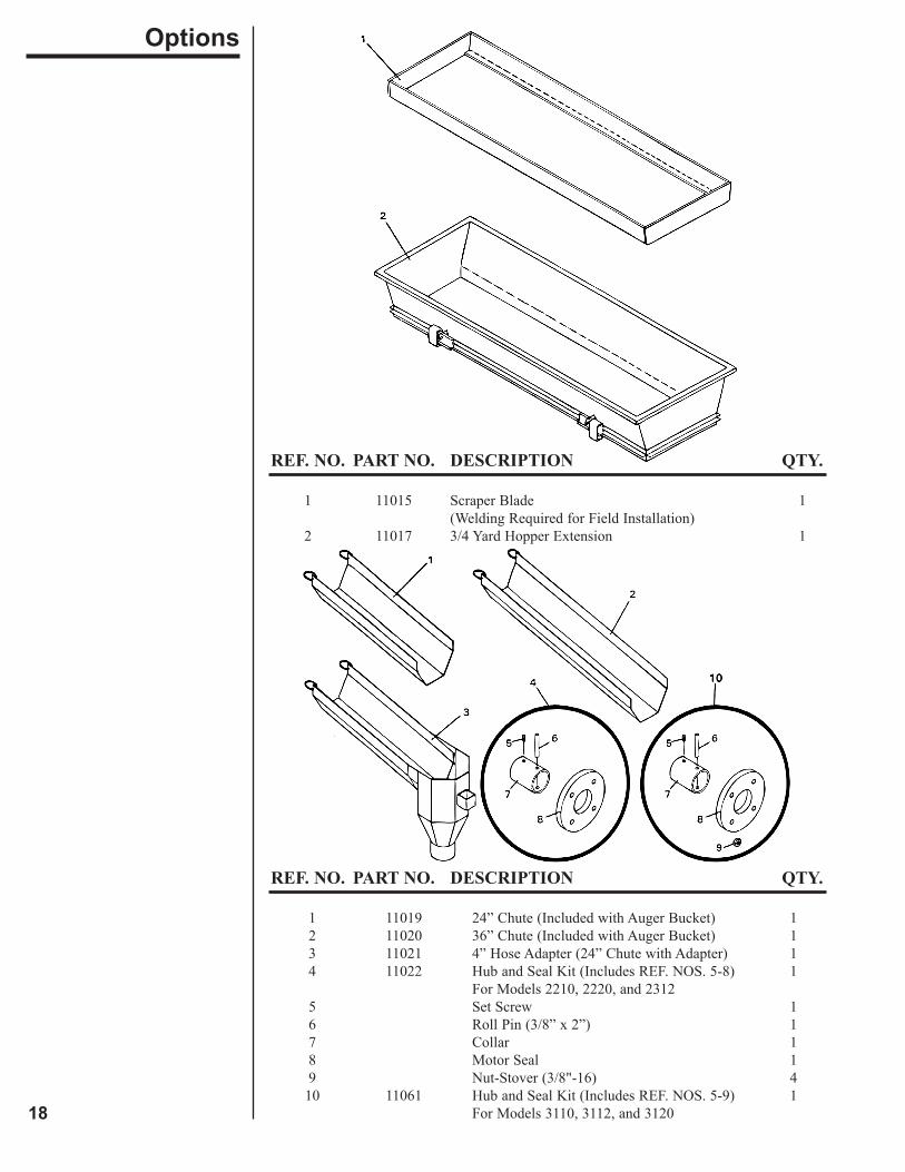
REF. NO. PART NO. DESCRIPTION QTY.
1 11015 Scraper Blade 1 (Welding Required for Field Installation) 2 11017 3/4 Yard Hopper Extension 1
REF. NO. PART NO. DESCRIPTION QTY.
1 11019 24” Chute (Included with Auger Bucket) 1 2 11020 36” Chute (Included with Auger Bucket) 1 3 11021 4” Hose Adapter (24” Chute with Adapter) 1 4 11022 Hub and Seal Kit (Includes REF. NOS. 5-8) 1 For Models 2210, 2220, and 2312 5 Set Screw 1 6 Roll Pin (3/8” x 2”) 1 7 Collar 1 8 Motor Seal 1 9 Nut-Stover (3/8"-16) 4 10 11061 Hub and Seal Kit (Includes REF. NOS. 5-9) 1 For Models 3110, 3112, and 3120
Options
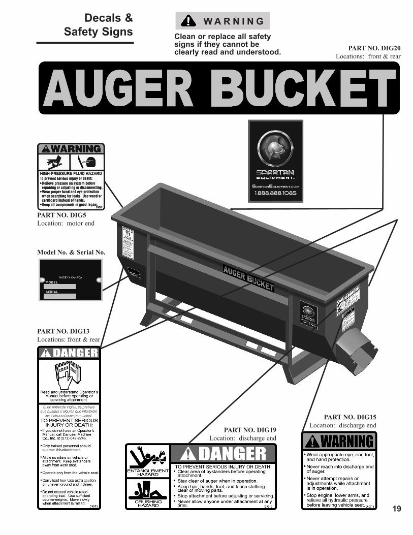
Clean or replace all safetysigns if they cannot beclearly read and understood.
W A R N I N G
PART NO. DIG20Locations: front & rear
19
Decals &Safety Signs
PART NO. DIG15Location: discharge end
PART NO. DIG19Location: discharge end
Model No. & Serial No.
PART NO. DIG13Locations: front & rear
PART NO. DIG5Location: motor end
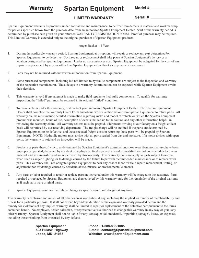
Spartan EquipmentLIMITED WARRANTY
Spartan Equipment warrants its products, under normal use and maintenance, to be free from defects in material and workmanship for periods specified below from the purchase date from an authorized Spartan Equipment Dealer. Start of the warranty period is determined by purchase date given on your returned WARRANTY REGISTRATION FORM. Proof of purchase may be required. This Limited Warranty is extended only to the original purchaser of Spartan Equipment products.
Auger Bucket - 1 Year
1. During the applicable warranty period, Spartan Equipment, at its option, will repair or replace any part determined by Spartan Equipment to be defective. Such repair or replacement shall take place at Spartan Equipment's factory or a location designated by Spartan Equipment. Under no circumstances shall Spartan Equipment be obligated for the cost of any repair or replacement by anyone other than Spartan Equipment without its express written consent.
2. Parts may not be returned without written authorization from Spartan Equipment.
3. Some purchased components, including but not limited to hydraulic components are subject to the inspection and warranty of the respective manufacturer. Thus, delays in a warranty determination can be expected while Spartan Equipment awaits their decision.
4. This warranty is void if any attempt is made to make field repairs to hydraulic components. To qualify for warranty inspection, the “failed” part must be returned in its original “failed” condition.
5. To make a claim under this warranty, first contact your authorized Spartan Equipment Dealer. The Spartan Equipment Dealer shall complete the Warranty Claim Form and obtain written authorization from Spartan Equipment to return parts. All warranty claims must include detailed information regarding make and model of vehicle on which the Spartan Equipment product was mounted, hours of use, description of events that led up to the failure, and any other information helpful in reviewing the warranty claim. All warranty returns must be prepaid. Shipments arriving at our factory on a freight collect basis will be refused by our receiving department. The freight charge will be credited if the parts are determined by Spartan Equipment to be defective, and the associated freight costs in returning those parts will be prepaid by Spartan Equipment. NOTE: Hydraulic motors must arrive with all ports sealed from dirt and moisture. If a motor arrives with open ports, the warranty is void and no inspection will be made.
6. Products or parts thereof which, as determined by Spartan Equipment's examination, show wear from normal use, have been improperly operated, damaged by accident or negligence, field repaired, altered or modified are not considered defective in material and workmanship and are not covered by this warranty. This warranty does not apply to parts subject to normal wear, such as auger flighting, or to damage caused by the failure to perform recommended maintenance or to replace worn parts. This warranty shall not obligate Spartan Equipment to bear any cost of labor for field repair, replacement, testing, or adjustment nor for damage caused by accident, abuse, misuse, or environmental elements.
7. Any parts or labor required to repair or replace parts not covered under this warranty will be charged to the customer. Parts repaired or replaced by Spartan Equipment are then covered by this warranty only for the remainder of the original warranty as if such parts were original parts.
8. Spartan Equipment reserves the right to change its specifications and designs at any time.
This warranty is exclusive and in lieu of all other express warranties, if any, including the implied warranties of merchantability and fitness for a particular purpose. It shall not extend beyond the duration of the expressed warranty provided herein and the remedy for violations of any implied warranty shall be limited to repair or replacement of the defective part pursuant to the terms contained herein. No employee, dealer, salesman, or representative is authorized to change this warranty in any way or grant any other warranty. Spartan Equipment shall not be liable for any consequential, incidental, or punitive damages, losses, or expenses, including those resulting from or caused by any defects.
Warranty
Spartan Equipment Phone: 1-888-888-1085503 Pulaski Highway E-mail: [email protected], MD 21085 Website: www.SpartanEquipment.com
Model #
Serial #