Auf dem Weg zum neuen weltweiten...
50
Auf dem Weg zum neuen weltweiten Flugfunkstandard L-DACS Uwe-Carsten Fiebig, Michael Schnell et al German Aerospace Center (DLR) Institute of Communications and Navigation Center of Excellence for SoL Communications
Transcript of Auf dem Weg zum neuen weltweiten...

Auf dem Weg zum neuen weltweiten Flugfunkstandard L-DACS
Uwe-Carsten Fiebig, Michael Schnell et al
German Aerospace Center (DLR)Institute of Communications and Navigation
Center of Excellence for SoL Communications

Auf dem Weg zum neuen weltweiten Flugfunkstandard LDACS – Fiebig, Schnell et al. Folie 2
The DLR L-DACS Team: Group leader: Michael SchnellPHY/MAC design: Sinja Brandes, Ulrich Epple, Snjezana Gligorevic, Michael WalterHigher layer issues: Serkan Ayaz, Felix HoffmannPrototyping: Alexander Arkhipov, Niko Franzen, Nikolas Schneckenburger
L-DACS Partners:Frequentis, University of SalzburgDeutsche FlugsicherungiAd, Rohde und SchwarzSelex Communications
L-DACS: L-Band Digital Aeronautical Communication System
Auf dem Weg zum neuen weltweiten Flugfunkstandard LDACS – Fiebig, Schnell et al. Folie 3
Some Remarks on DLR – Institute of Communications and Navigation
Motivating the new standard L-DACS
L-DACS PHY/MAC Layer
L-DACS Navigation - an option for APNT
Further Modernisation of Air Traffic Management (ATM) communications
AeroMacs (aeronautical WiMax) for airports environmentsNetworking the Sky
Content of the Presentation

Auf dem Weg zum neuen weltweiten Flugfunkstandard LDACS – Fiebig, Schnell et al. Folie 4
Oberpfaffenhofen, 20 km west of Munich
DLR – Institute of Communications and Navigation
Institutes:Communications and NavigationRadio Frequency TechnologyOptoelectronicsAtmospheric PhysicsRobotics and System Dynamics
Scientific-Technical Facilities:Research Flight Operations German Space Operations Center (GSOC)German Remote Sensing Data Center (DFD)Galileo Control Center (GCC)
Auf dem Weg zum neuen weltweiten Flugfunkstandard LDACS – Fiebig, Schnell et al. Folie 5
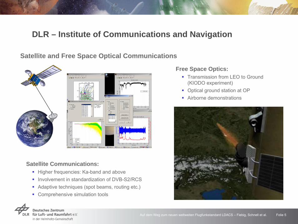
Satellite and Free Space Optical Communications
DLR – Institute of Communications and Navigation
Free Space Optics:Transmission from LEO to Ground (KIODO experiment)Optical ground station at OPAirborne demonstrations
Satellite Communications:Higher frequencies: Ka-band and aboveInvolvement in standardization of DVB-S2/RCSAdaptive techniques (spot beams, routing etc.)Comprehensive simulation tools

Auf dem Weg zum neuen weltweiten Flugfunkstandard LDACS – Fiebig, Schnell et al. Folie 6
Satellite Navigation
Validation of Galileo signals via Weilheim ground stationGalileo EvolutionMonitoring of the ionosphere
DLR – Institute of Communications and Navigation

Auf dem Weg zum neuen weltweiten Flugfunkstandard LDACS – Fiebig, Schnell et al. Folie 7
Ubiquitous Navigation
DLR – Institute of Communications and Navigation

Auf dem Weg zum neuen weltweiten Flugfunkstandard LDACS – Fiebig, Schnell et al. Folie 8
Ubiquitous Navigation
GPS + INS + Altimeter + LTE + WLAN + Maps + …
DLR – Institute of Communications and Navigation
IMU: XSens MTx-28A53G25 foot-mounted: right and left
Baro-Altimeter: IntersemaMS5540-C (mounted on laptop)
Electronic compass: OceanServerOS5000-US (mounted on hip)
GPS receiver: ublox EVK-5 (mounted on body)

Auf dem Weg zum neuen weltweiten Flugfunkstandard LDACS – Fiebig, Schnell et al. Folie 9
Aeronautical Communications for Air Traffic Management (ATM)
DLR – Institute of Communications and Navigation
ground network
air-air communications
satellite-based communications
ground-based communications
communications in and around airports

Auf dem Weg zum neuen weltweiten Flugfunkstandard LDACS – Fiebig, Schnell et al. Folie 10
Worldwide assigned frequency band: 117.975 – 137.000 MHz (VHF band) Channel spacing: 25 kHz
Till 1970: 50 kHz spacing25 kHz spacing allows for about 760 channels
Modulation: DSB-AM
TDD mode; simultaneous transmission and reception not possibleCellular system with 11,000 VHF assignments worldwide today
Same frequency can be reassigned provided there are no interference problemsGerman speaking area: 67 “25 kHz channels” in use mainly in 122.000 – 123.675 MHz for 200 airports and 300 gliding airfields
f
Spectrum of voice signal
fT
Bandwidth of DSB-AM signal
25 kHz
Aeronautical VHF Communication

Auf dem Weg zum neuen weltweiten Flugfunkstandard LDACS – Fiebig, Schnell et al. Folie 11
VHF Assignments Munich Airport
Aeronautical VHF Communication

Auf dem Weg zum neuen weltweiten Flugfunkstandard LDACS – Fiebig, Schnell et al. Folie 12
Capacity Limitations: In crowded flight areas, there are by far not enough 25 kHz channels available to serve all aircraft !!
SolutionRe-sectorisation (limited)Smaller sectors (limited due to interference) Optimising frequency re-use (limited)More spectrum: 118-136 MHz band increased to 118-137 MHz in 1979Signals with smaller bandwidth
The VHF ATM 8.33 kHz Expansion ProgrammeIn 1994 ICAO decided to introduce a channel split from 25 to 8.33 kHz. 8.33 kHz spacing was introduced above FL245 (24,000 ft) in the ICAO EUR Region in 1999.8.33 kHz is mandatory above FL195 in the ICAO EUR Region since 15 March 2007.These States enforced mandatory carriage above FL 195 from 13 March 2008: Bulgaria, Cyprus, Malta, Portugal, Spain.
Aeronautical VHF Communication

Auf dem Weg zum neuen weltweiten Flugfunkstandard LDACS – Fiebig, Schnell et al. Folie 13
8.33 kHz spacing will not solve problems of 2020 ++
Situation in Europe:Traffic in 2004:
8 million flights per yearNumber of flights on peak days:
30,000 by commercial airlines200,000 by general aviationNumerous military aircraft
Estimated traffic in 2020: 16 million flights per year
Estimated traffic in 2025:22 million flights per yearNumber of flights on peak days:
72,000 by commercial airlines480,000 by general aviation aircraftNumerous military aircraft
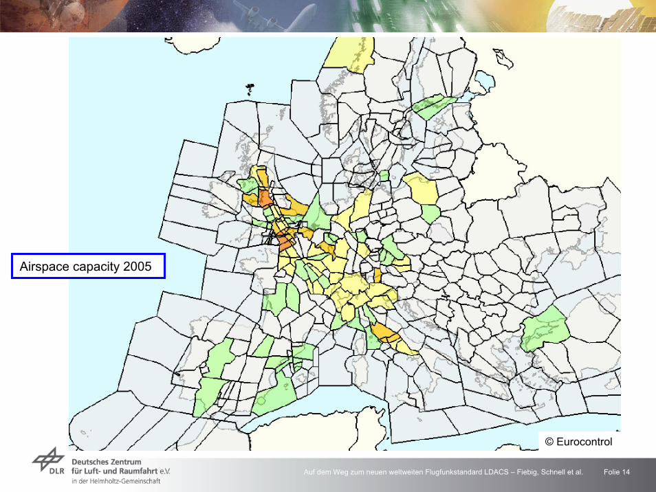
Today's ATM Communication Systems are at Capacity Limits
© Eurocontrol
Auf dem Weg zum neuen weltweiten Flugfunkstandard LDACS – Fiebig, Schnell et al. Folie 14
Airspace capacity 2005
© Eurocontrol

Auf dem Weg zum neuen weltweiten Flugfunkstandard LDACS – Fiebig, Schnell et al. Folie 15
Airspace capacity 2010
© Eurocontrol
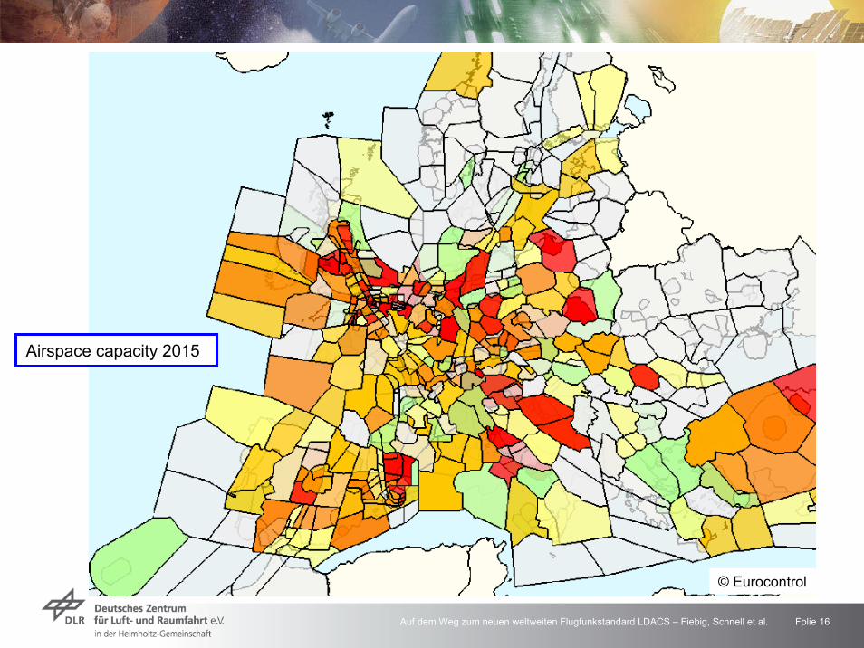
Auf dem Weg zum neuen weltweiten Flugfunkstandard LDACS – Fiebig, Schnell et al. Folie 16
Airspace capacity 2015
© Eurocontrol
Auf dem Weg zum neuen weltweiten Flugfunkstandard LDACS – Fiebig, Schnell et al. Folie 17
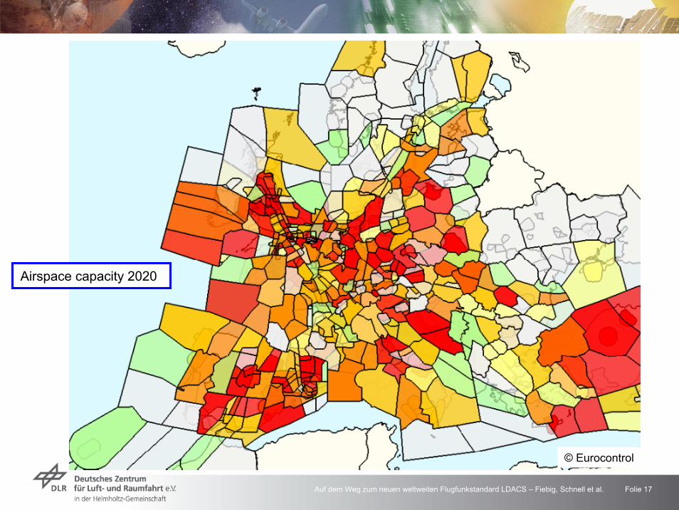
Airspace capacity 2020
© Eurocontrol

Auf dem Weg zum neuen weltweiten Flugfunkstandard LDACS – Fiebig, Schnell et al. Folie 18
8.33 kHz spacing will not solve problems of 2020 ++
Apart from air traffic increase there is a huge demand for new data services
Tracker Controller Radar Assistant Controller
Today: LIMITED CAPACITY
Radar Controller Tracker Controller / Automatisation
Radar Assistant Controller /
Automatisation
Radar Controller
Advanced Decision Support Tools
Data Comm
Data Comm
Data Comm
Source: FAA
Today's ATM Communication Systems are at Capacity Limits

Auf dem Weg zum neuen weltweiten Flugfunkstandard LDACS – Fiebig, Schnell et al. Folie 19
The ATM Communications System after 2020
No further increase of spectral efficiency in the VHF band (8.33 kHz channels) possibleToday’s data communication standards support only low bit-rate services
Open new frequency bands for aeronautical communication (WRC-07)VHF band: 108 -118 MHz (no system proposed – not enough B/W)L-band: Portions within the 960-1164 MHz for L-DACS
Challenge: Coexistence with DME (Distance Measurement Equipment)C-band: Portions within the 5000-5150 MHz for IEEE802.16aero
Development of a satellite component for ATM
Towards Tomorrow’s ATM Communication Systems
Standard Modulation Data rate Access CommentsVDL Mode 1 FSK 2.4 kbit/s CSMA Identical with ACARSVDL Mode 2 D8PSK 31.5 kbit/s CSMA
TDMATDMA
Currently introduced in EU, not yet mandatoryVDL Mode 3 D8PSK 31.5 kbit/s Candidate for US; not yet applied, uncertainVDL Mode 4 GFSK 19.2 kbit/s Newest standard; application uncertain

Auf dem Weg zum neuen weltweiten Flugfunkstandard LDACS – Fiebig, Schnell et al. Folie 20
About the history We started in 2004 with the EU project B-VHF initiated by Frequentis and DLRIn 2007 we redesigned B-VHF to became B-AMC Our response to ECTL/FAA’s “Future Communications Study” in 2008 is L-DACS1
L-DACS: L-Band Digital Aeronautical Communications System
Continental
Oceanic/Remote
Airport
Continental
Oceanic/Remote
Airport
•P34/TIA -902•LDL•W-CDMA
•Inmarsat SBB•Custom Satellite
•IEEE 802 -16e
•P34/TIA -902•LDL•W-CDMA
•Inmarsat SBB•Custom Satellite
•IEEE 802 -16e
United States Europe
•B-AMC•AMACS•Custom Satellite
Continental
Oceanic/Remote
Airport
Continental
Oceanic/Remote
Airport
•P34/TIA -902•LDL•W-CDMA
•Inmarsat SBB•Custom Satellite
•IEEE 802 -16e
•P34/TIA -902•LDL•W-CDMA
•Inmarsat SBB•Custom Satellite
•IEEE 802 -16e
United States EuropeCommon shortlist /Screening Results
•B-AMC•AMACS•Custom Satellite
Source: Eurocontrol/FAA
FAA ranking: B-AMC best performance
ECTL ranking:B-AMC first
B-AMC chosen as baseline for L-DACS1

Auf dem Weg zum neuen weltweiten Flugfunkstandard LDACS – Fiebig, Schnell et al. Folie 21
Thus, since 2009 there are two proposals:L-DACS1 and L-DACS2
Today, L-DACS1 is the strongest candidate
Options Access Scheme Modulation Origins
L-DACS-1 FDD OFDMB-AMC (B-VHF) by DLR (2004++)
TIA 902 (P34) (US)
L-DACS-2 TDD CPFSK / GMSK type LDL (US), AMACS (DSNA, LFV)
Flight Guidance France (DSNA) and Sweden (LFV)
DLR, Frequentis, Uni Salzburg, Selex Communications
AMACS: All-purpose Multi-channel Aviation Communication System (new development); B-AMC: Broadband Aeronautical Multi-Carrier Communications (B-VHF for L-band); B-VHF: Broadband VHF Communications System (new development); LDL: L-Band Digital Link (VDL Mode 3 for L-band); P34: Public Safety Standard (US standard, e.g. for fire brigades etc.)
Development of L-DACS

Auf dem Weg zum neuen weltweiten Flugfunkstandard LDACS – Fiebig, Schnell et al. Folie 22
L-Band Frequency Assignments
SSR
SSR
DM
Enat. B
asis
DME DME DME
UA
T
JTIDS
969 1008
JTIDS
1053 1065
JTIDS (MIDS)
1113 1213
-1 -0.8 -0.6 -0.4 -0.2 0 0.2 0.4 0.6 0.8 1-160
-150
-140
-130
-120
-110
-100
-90
-80
-70
-60
frequency [MHz]
norm
aliz
ed p
ower
spe
ctra
l den
sity
[dBm
/Hz]
Assignment for AM(R)S at WRC 2007(960 – 1164 MHz)GSM Galileo/GPS
DME (1157-1213)
960 11641150978 1025 1035 1085 1095
Development of L-DACS1

Auf dem Weg zum neuen weltweiten Flugfunkstandard LDACS – Fiebig, Schnell et al. Folie 23
L-Band: Assignment of L-DACS frequencies
GSM
960
SSR
SSR
11641150
DME DME DME
UA
T
978 1025 1035 1085 1095
JTIDS
969 1008
JTIDS
1053 1065
JTIDS (MIDS)
1113 1213
L-DACS 1 A/G FL(crowded areas)L-DACS 1 A/A
L-DACS 1 A/G FL(no airborne DME)
L-DACS 1 A/G RL
L-DACS 1 A/G RL(optional)
Galileo/GPSDME (1157-1213)
L-DACS 1 A/G RL(crowded areas)L-DACS 1 A/A
Development of L-DACS1

Auf dem Weg zum neuen weltweiten Flugfunkstandard LDACS – Fiebig, Schnell et al. Folie 24
Fitting L-DACS1 into the DME frequency grid
A/G Data LinkAvailable bandwidth: 500 kHz per channelChallenges:
Minimize interferenceto other systems(out-of-band radiation)Minimize interferencefrom other systems(robustness)Take into accountmainly DME system
-1 -0.8 -0.6 -0.4 -0.2 0 0.2 0.4 0.6 0.8 1-180
-160
-140
-120
-100
-80
frequency [MHz]
norm
aliz
ed p
ower
spe
ctra
l den
sity
[dB
m/H
z]
DMEB-AMCL-DACS-1
Development of L-DACS1

Auf dem Weg zum neuen weltweiten Flugfunkstandard LDACS – Fiebig, Schnell et al. Folie 25
Key Features of L-DACS-1
Based on OFDM
Centralized communication via ground station
Cellular deployment concept
Inlay system between DME channels
Duplex scheme is FDD (Frequency-Division Duplex)
More efficient than TDD (Time-Division Duplex)
Separate FL/RL channels advantageous for inlay design
Multiple-access schemes
Forward link: OFDM(A), incl. pure OFDM as special case
Reverse link: OFDM(A) combined with TDMA
A/G mode supports data and voice communication
Development of L-DACS1

Auf dem Weg zum neuen weltweiten Flugfunkstandard LDACS – Fiebig, Schnell et al. Folie 26
A/G Data Link System Parameters
Main system parametersBandwidth (overall / occupied) 625 / 488,28 kHzNumber of subcarriers 64 (50 used)Sub-carrier spacing 625/64 = 9.765625 kHzOFDM symbol duration 120 µsOverall guard time duration 17.6 µs= RC-window + guard = 12.8 µs + 4.8 µsOFDM symbols per data frame 54 (forward link)
Data rates & adaptive coding and modulationModulation rate (overall FL + RL) 833.33 ksymbols/sMin. net data rate (QPSK) 291/270 kbit/sMax. net data rate (64-QAM) 1318/1267 kbit/s
Development of L-DACS1

Auf dem Weg zum neuen weltweiten Flugfunkstandard LDACS – Fiebig, Schnell et al. Folie 27
A/G Data Link – Frame Structure
Development of L-DACS1 RA: Random Access frame net entry)BC: Broadcast Channel (cell information broadcast)DC: Dedicated Control channel (resource requests)CC: Common Control channel (resource assignment)
Multiframe 1(58,32 ms)
Multiframe 2(58,32 ms)
Multiframe 3(58,32 ms)
Multiframe 4(58,32 ms)
RA
Superframe (240 ms)
Multiframe 1(58,32 ms)
Multiframe 2(58,32 ms)
Multiframe 3(58,32 ms)
Multiframe 4(58,32 ms)
BC
BC FL
RL
6,72 ms
RA 1 RA 2 DataDC
Data DataCC

Auf dem Weg zum neuen weltweiten Flugfunkstandard LDACS – Fiebig, Schnell et al. Folie 28
A/G Forward Link – Frame Structure (Data and CC Frame)f
t Sync Symbol
Null Symbol
Pilot Symbol (158)Data Symbol (2442)
DME-Interferenz
Development of L-DACS1
Sync symbols proceedeach Data/CC frame(every 6.48 ms) and the BC frames (3 within 6.72 ms @ SF start).
Pilot symbols cover Data/CC frame with a regular pattern; pilot arrangement in rows avoided.
Auf dem Weg zum neuen weltweiten Flugfunkstandard LDACS – Fiebig, Schnell et al. Folie 29
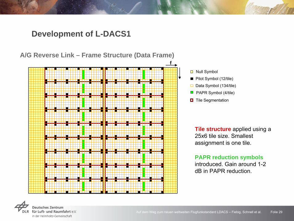
A/G Reverse Link – Frame Structure (Data Frame)
PAPR Symbol (4/tile)
Null Symbol
Pilot Symbol (12/tile)
Data Symbol (134/tile)
Tile Segmentation
f
Development of L-DACS1
Tile structure applied using a 25x6 tile size. Smallest assignment is one tile.
PAPR reduction symbolsintroduced. Gain around 1-2 dB in PAPR reduction.

Auf dem Weg zum neuen weltweiten Flugfunkstandard LDACS – Fiebig, Schnell et al. Folie 30
Example of worst case DME interference
NormalizedDME power in the frequency
domain
Development of L-DACS1

Auf dem Weg zum neuen weltweiten Flugfunkstandard LDACS – Fiebig, Schnell et al. Folie 31
DME Double Pulse
4.9 5 5.1 5.2 5.3 5.4 5.5 5.6x 10⁻⁴
0
0.5
1
1.5
2
2.5
3
3.5
4
4.5
5
t in s
ampl
itude
DME pulsesDME pulses after pulse blankingDME pulses after clipping
threshold
DME pulses occur always as pairsDME pulse duration (above threshold) is 3.5 μs
Development of L-DACS1

Auf dem Weg zum neuen weltweiten Flugfunkstandard LDACS – Fiebig, Schnell et al. Folie 32
Development of L-DACS1
Interference Mitigation: Pulse BlankingPrinciple of pulse blanking (PB)
Define a threshold for the time domain samplesSet received samples to zero, if its amplitude exceeds threshold
0
1
2
3
4
5
6
7Received SignalSignal after Pulse BlankingThreshold

Auf dem Weg zum neuen weltweiten Flugfunkstandard LDACS – Fiebig, Schnell et al. Folie 33
0
1
2
3
4
5
6
7Received SignalSignal after Pulse BlankingThreshold
0
1
2
3
4
5
6
7Received SignalSignal after Pulse BlankingThresholdDifference Signal
Use difference signal between outer and inner subcarriers
Clear distinction between LDACS1 and interference signal
Development of L-DACS1
Interference Mitigation: Pulse BlankingAdvantage: No knowledge about the interference has to be known in advanceProblem: OFDM signal peaks (due to PAPR) may be interpreted as interference

Auf dem Weg zum neuen weltweiten Flugfunkstandard LDACS – Fiebig, Schnell et al. Folie 34
OFDM symbol w/o PB
time
OFDM symbol with PB
oT
oT ′
Development of L-DACS1
Interference Mitigation: Pulse BlankingDrawback of pulse blanking
Cutting out interference pulses affects useful signalImpact on OFDM signal – loss of orthogonality ICI
Countermeasure – pulse blanking compensation (PBC)Manipulation (pulse blanking) of received signal exactly knownImpact on OFDM signal can be compensated/mitigatedIterative scheme using estimated channel and estimated data

Auf dem Weg zum neuen weltweiten Flugfunkstandard LDACS – Fiebig, Schnell et al. Folie 35
PB improves performance considerably(2 dB gain)
Realistic PB achieves almost ideal performance
PB with PBC further improves performance(another 2 dB)
Remaining gap due to imperfect estimation (data, channel), SNR degradation, and remaining pulse interference
0 1 2 3 4 5 6 7 810-6
10-5
10-4
10-3
10-2
10-1
100
SNR [dB]
BE
R
w/o DMEw/ DMEw/ DME, perf. PBw/ DME, real. PB
0 1 2 3 4 5 6 7 810-6
10-5
10-4
10-3
10-2
10-1
100
SNR [dB]
BE
R
w/o DMEw/ DMEw/ DME, perf. PBw/ DME, real. PBw/ DME, real. PBC, 1 iter.w/ DME, real. PBC, 2 iter.
Development of L-DACS1
Interference Mitigation: Simulation Results
Auf dem Weg zum neuen weltweiten Flugfunkstandard LDACS – Fiebig, Schnell et al. Folie 36
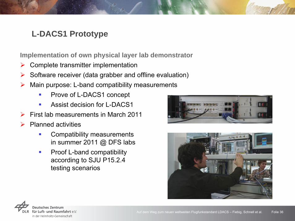
L-DACS1 Prototype
Implementation of own physical layer lab demonstratorComplete transmitter implementationSoftware receiver (data grabber and offline evaluation)Main purpose: L-band compatibility measurements
Prove of L-DACS1 conceptAssist decision for L-DACS1
First lab measurements in March 2011Planned activities
Compatibility measurementsin summer 2011 @ DFS labsProof L-band compatibilityaccording to SJU P15.2.4testing scenarios

Auf dem Weg zum neuen weltweiten Flugfunkstandard LDACS – Fiebig, Schnell et al. Folie 37
Imag
inar
y pa
rt, n
orm
aliz
ed
Real part, normalized
64-QAM Signal Constellation
Interference L-DACS1 DME
Criteria (60s) fulfilled for D/U ≥ -12 dBReal D/U = 22 dBMargin: 34 dB
Measurement results with DLR L-DACS1 laboratory demonstratorFirst measurement campaign at DFS labs, March 2011
L-DACS1 Prototype

Auf dem Weg zum neuen weltweiten Flugfunkstandard LDACS – Fiebig, Schnell et al. Folie 38
Towards APNT: Alternative Positioning, Navigation, Timing
APNT approach:Increase DME density and use DME for multilateration
DME system already availableCostly extension of infrastructureEndangers sustainable use of L-band for communications
L-band foreseen for future A/G communicationFuture A/G system shall be long-term solution
Our alternative approach:Integrate a navigation functionality into the L-DACS communications system
No additional DME ground stations requiredEven partial removal of DME infrastructure possibleAssures sustainable use of L-band for both communications and navigation

Auf dem Weg zum neuen weltweiten Flugfunkstandard LDACS – Fiebig, Schnell et al. Folie 39
xxx
Enroute flightacross Germany
500 1000 1500 2000 2500 300020
30
40
50
60
70
80
90
100
time [s]
no. g
roun
d st
atio
ns
visible ground stations
L-DACS ground stations
L-DACS1 for APNT – Performance Assessment

Auf dem Weg zum neuen weltweiten Flugfunkstandard LDACS – Fiebig, Schnell et al. Folie 40
3 StationsSNR only
10 StationsSNR only
P1 circleSnapshot WLSP2 dotEKF, correlationsP3 solid curveCRLB on position error, real sync
ENR FlightAcross GermanyL-DACS1 for APNT – Performance Assessment
Auf dem Weg zum neuen weltweiten Flugfunkstandard LDACS – Fiebig, Schnell et al. Folie 41
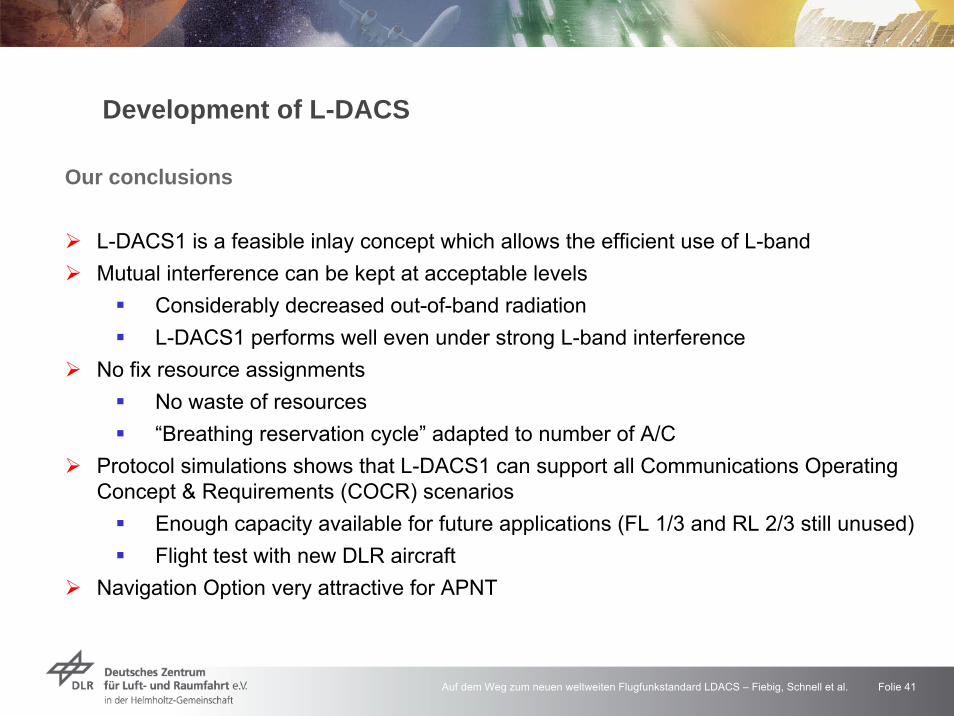
Our conclusions
L-DACS1 is a feasible inlay concept which allows the efficient use of L-bandMutual interference can be kept at acceptable levels
Considerably decreased out-of-band radiation L-DACS1 performs well even under strong L-band interference
No fix resource assignmentsNo waste of resources“Breathing reservation cycle” adapted to number of A/C
Protocol simulations shows that L-DACS1 can support all Communications Operating Concept & Requirements (COCR) scenarios
Enough capacity available for future applications (FL 1/3 and RL 2/3 still unused) Flight test with new DLR aircraft
Navigation Option very attractive for APNT
Development of L-DACS

Auf dem Weg zum neuen weltweiten Flugfunkstandard LDACS – Fiebig, Schnell et al. Folie 42
Aeronautical Communications for Air Traffic Management
DLR – Institute of Communications and Navigation
ground network
air-air communications
satellite-based communications
ground-based communications
communications in and around airports

Auf dem Weg zum neuen weltweiten Flugfunkstandard LDACS – Fiebig, Schnell et al. Folie 43
Towards a data link for ATM airport services, mainly A-SMGCS
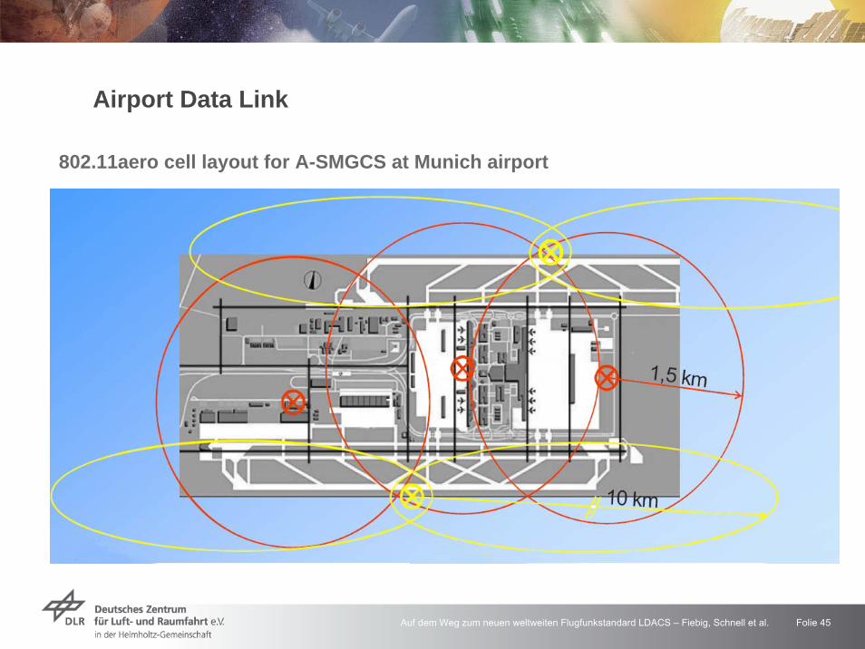
Airport Data LinkEU project EMMAChannel measurement campaign (C-band) at Munich airportChannel modeling of airport channel (taxiing, parking,take-off/landing)Development of a new datalink for A-SMGCS
Exact guiding ofaircraft on airports(space and time)Optimization of aircraftthroughput
Baseline: IEEE 802.16a(WiMAX)Goal: IEEE 802.16aero
Airport Data Link

Auf dem Weg zum neuen weltweiten Flugfunkstandard LDACS – Fiebig, Schnell et al. Folie 44
Airport Data Link
Auf dem Weg zum neuen weltweiten Flugfunkstandard LDACS – Fiebig, Schnell et al. Folie 45
802.11aero cell layout for A-SMGCS at Munich airport
Airport Data Link

Auf dem Weg zum neuen weltweiten Flugfunkstandard LDACS – Fiebig, Schnell et al. Folie 46
Aeronautical Communications for Air Traffic Management
DLR – Institute of Communications and Navigation
ground network
air-air communications
satellite-based communications
ground-based communications
communications in and around airports

Auf dem Weg zum neuen weltweiten Flugfunkstandard LDACS – Fiebig, Schnell et al. Folie 47
Aeronautical Communications for Air Traffic Management
DLR – Institute of Communications and Navigation
ground network
air-air communications
satellite-based communications
ground-based communications
communications in and around airports
Auf dem Weg zum neuen weltweiten Flugfunkstandard LDACS – Fiebig, Schnell et al. Folie 48
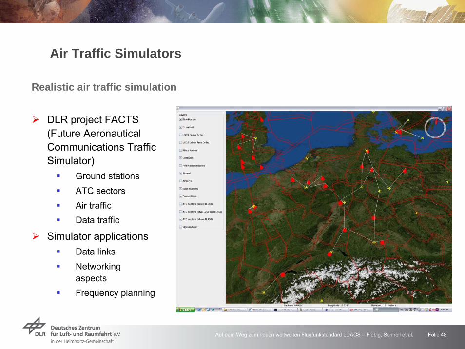
Realistic air traffic simulation
Air Traffic Simulators
DLR project FACTS (Future Aeronautical Communications Traffic Simulator)
Ground stationsATC sectorsAir trafficData traffic
Simulator applicationsData linksNetworkingaspectsFrequency planning

Auf dem Weg zum neuen weltweiten Flugfunkstandard LDACS – Fiebig, Schnell et al. Folie 49
DFS (Deutsche Flugsicherung) and BMVBS (Bundesministerium fürVerkehr, Bau und Stadtentwicklung)
Advisor of DFS and BMVBW in the ACP (Aeronautical CommunicationsPanel) of ICAOSupport of DFS for standardisation issues and in course of the preparation of decisions
ICAO (International Civil Aviation Organisation)Member of WG-T „Technology“ of ACPMember of WG-I “Internet Protocol Suite” of ACP
EurocontrolMember in NexSAT (Next Generation Satellite System) Steering GroupMember in AGC-FG (Air-Ground Communications Focus Group)
Contributions to International Panels

Auf dem Weg zum neuen weltweiten Flugfunkstandard LDACS – Fiebig, Schnell et al. Folie 50
Vielen Dank für Ihre Aufmerksamkeit
Modernisierung des Flugfunks
… und wann immer und wohin Sie auch fliegen: Guten Flug !