Audun Haugs - NFOGM
19
NORWEGIAN SOCIETY OF CHARTERED ENGINEERS NC>R TH SEA FLOW METER I NC WORKSHOP 13 - 15 October 1987 Stavanger Forum, Stavanger DEFLECTION OF ORIFICE PLATES AT HIGH DIFFERENTIAL PRESSURE by Jim Fulton Erling A. Hammer Audun Haugs All rights reserved NIF and the Authm· BPC UiB CMI Main Index
Transcript of Audun Haugs - NFOGM

NORWEGIAN SOCIETY OF CHARTERED ENGINEERS
NC>R TH SEA FLOW METER I NC
WORKSHOP
13 - 15 October 1987
Stavanger Forum, Stavanger
DEFLECTION OF ORIFICE PLATES AT HIGH DIFFERENTIAL PRESSURE
by
Jim Fulton Erling A . Hammer Audun Haugs
All rights reserved NIF and the Authm·
BPC UiB CMI
Main Index

!' ... ~ :~:: : ~
:. : ' 1 ., i l
.,
. ! '
.<1 . ' f. ... ~
,, . ·'·
•
North Sea Flow Metering Workshop
No~lan Society of Chartered Engineers Department of Further Education
Stavanger Forum. Stavanger 13 -15 October 1987.
Deflection of Orifice Plates at High Differential Pressure
by
Jim Fulton BPC Erling A. Hammer UiB Audun Haugs CMI

.~ ,,r.
: . t. '
·' . ·'
· · a \ . ; •..
' i~
t ·' ' - ~
, ; .::: I~~
.e . I
j
- 1 -
SUMMARY
This paper des~ribes the wor~ carried out at Chr . Michelsen Institute in Bergen to investigate experimentaly, the defle~~i0n of orifice plates under varying Differential Pressure (DP) ·: ·:•ndi tions.
The project was sponsored by Statfjord Division. and involved the construction of a full scale test rig with compon~nts identical to those used on meter station~ in the Statfjord Fie ld .
The purpose of the test was to prove that the theoreti cal formula used by "Jeps·:·n and Chipchase" tt.:• calculate o rifii:::e plate deflection, t.Jas equaly valid wh·2 n applied to ac t.ual of fsh·:·re equipment, and thence to establish the a c tual levels of mea surement uncertainty at flow conditions up ~o 1000 mbar .
c' ·' :
. ., •'
: . . . ~: .. '
. ~ • I ' ... .. .
· : ~
-~: ... ':' • .··: W
--
... '
- 2 ·-
INTRODUCTION
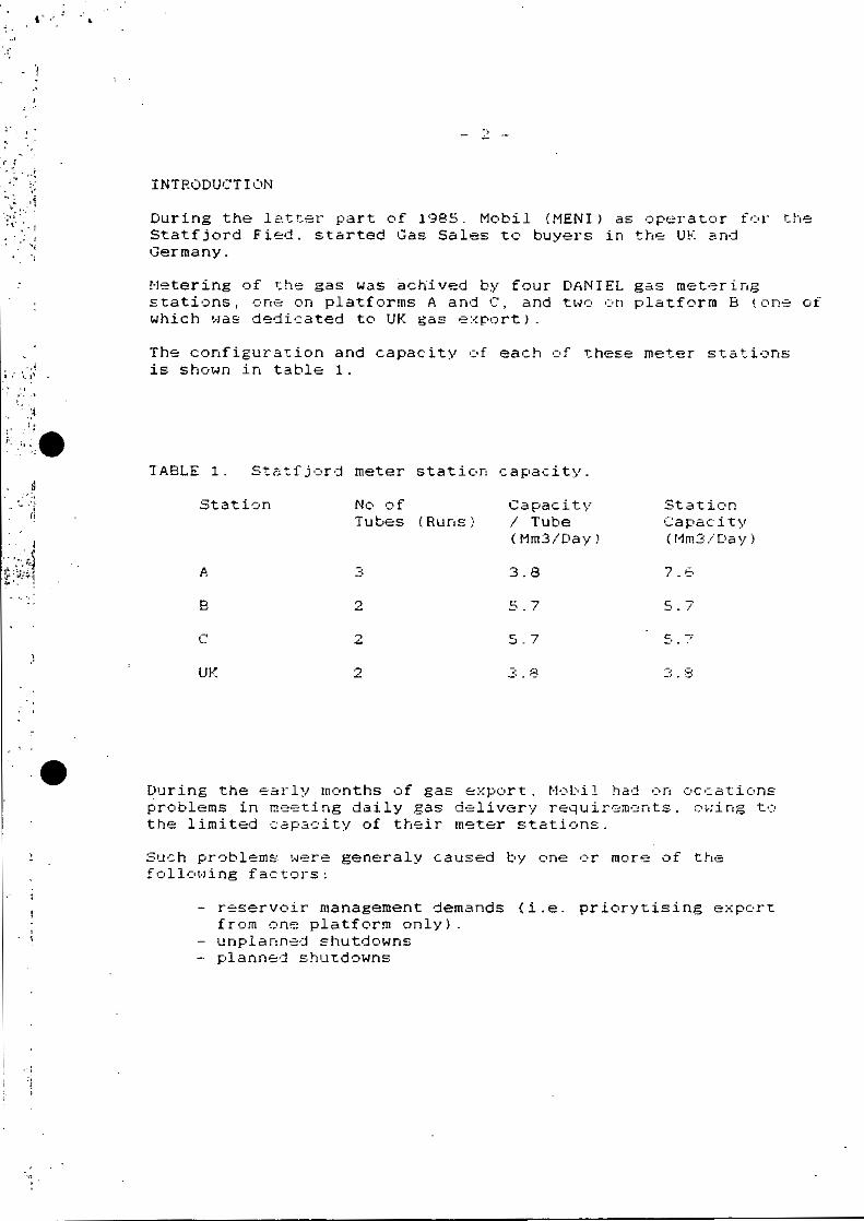
During the l atter part of 1985. Mobil !MENI J as operator f0r the Statfjord Fied. started Gas Sales to buyers in the UK and Germany .
Metering of the gas was ~chived by four DANIEL gas metering stations, one on platforms A and C, and t wo on platform B ! o ne of which was dedicated to UK gas e~portJ.
The configuration and capacity of each of ~hese meter s t a t i ons is shown in table 1 .
TABLE 1 . Statfjord meter station capacity.
Station No of Capacity Station Tubes (Runs) I Tube Capacity
(Mm3/ Day) (Mm3/[1a y)
3 3.8 7.6
8 2 5.7 5 . 7
c 2 5.7 c: , _, .. .
UK 2 3. 8 3. ~~
During the early months of gas export . Mobil had on occa~ions problems in meeting daily gas delivery requirem~nts , o wing to the limited ~ap~city of their meter stations .
Such problems were generaly caused by one or more of the following fac tors:
- reservoir management demands (i . e. priory~ising export from one platform only). unplann~d s h utdowns
- planned s hu tdowns

• J . ,:]
: / . ~
\ ... .. .. ~·~·r.: ...
. I
..... "'. e . ~
~
. I
; L.· .
>.
•; ., l .
'
:l
.,
. ...
\ . . .
3 -
The options which were considered for resolving this capa~ity problem were:
1 . Installation of additional meter tubes 011 all platforms. 2. Use the spare meter run. 3. Increasing the range of the DP cells . 4. Increasing orifice plate Beta Ratio's.
Option number 1. was evaluated but rejected because of cost, weight and space restrictions.
Option number 2. could be used in the shorc term . but would jeopardise the reliability and maintainability of the meter stations.
Option numbers 3 and 4 could be easily applied. but wou l d contravene existing NOP regulati ons wh ich limit DP t o 500 mbar and Beta Ratios to 0.6 .
Of these four options, the most attractive (fr0m an op~rating standpoint) uas 3., if approval could be obtained from th~ appropriate Norwegian and British authorities.
With that thought in mind , Mobil approached CHI . ear l v in 1986. to inquire about the possibility of undertaking full scale test to investigate the deflection o f orif ice plates under flow conditions exceeding 500 mbar.
If it could be established, that the amount o f deflection at high DP was less than 13 and that the mass flow me asurement error was less than 0.13 then Mobil felt that they wou ld have a good chance of obtaining relaxation from current authoritv requirements.

.. . ~, :.:·
I • . · •
.· t
·i
• ,, J . ~
.. ·,i ·~
; . . ~ . I
': ,, ., . ·~ ·l
· ·:-~ .
- 4 -
TECHNICAL BACKGROUND
Present regulations for fiscal gas metering, toth in No rway and the United Kingdom, require that the range of the differential pressure for orifice plate measurement in fiscal metering syst~ms to be limited to 500 mbar and 0.6 Beta Ratio. In the United Kingdom, however, Department of Energy guidelines provide allowance for exceeding the 500 ~bar limit. if the total orifice plate deflection is less than 13, and the mass flow measurement error is less than 0.1~ .
In November 1985 MOBIL Gas Dispatch Centre carried out a calculation study into inc reasing the Differential Pressure measurement of all the gas metering systems o n the Statfjord platforms. This increase was required to improve the operat ional flex ibili ty of gas sales fr o m the StatfJord field.
The orifice plate deflection calculations were based c•n a f ormula given by Messr. Jepson and Chipchase in a pa pe r publ ished in the Journal of Mechanical Engineering in 1975.
The Jepson and Chipchase formula allows calculation of both deflection and assoc iated flow error for various Beta Ratio plates. The original resear c h was carried out by the British Gas at their Killingworth research station in The North East o f England, and utilized plates mounted rigidl y between flanges . This experimental wo rk however , involved working at differential pressures fr om O - 120 mbar . (Figure 1. }
Direction or flow
Deflected orifice plate
Note: all dimensions art inches
Dlfferenbal pressure tappin9s
Figure 1. Jepson and Chipchase Orifice-plate fixing arrangement.

. '
# • • ,.. •',.
~ ..... ' ·
•!
· .~1 .' . •:'"
. : . ' •{
• I
:.: .. " i.. .. : • •
.. ;·: ·- ~ (
'";'. ,
'
- s -
The orifice fittings used in the Statf jord gas metering stations are DANIEL Senior Carriers. The seal rings used in these orifice carriers are made of stainless steel and compl y fully with ISO 5167, Rev . 80. These ~~al rings do not provide the same rigid mounting as obtained for the flange mounted plates tested by Jepson and Chipchase. It was therefore of great interest to verify if the Jepson and Chipchase formula is equally valid for the type seal rings used offshore, and operating at differential pressure up to 1000 mbar. ·
THE TEST RIG
A test rig was designed to simulate as far as possible the conditions found on offshore gas meter stations, and comprised the following main parts: (Figure 2)
- Air reservoir and supply source . To ensure a controlled air pressure during the tests, a buffer tank with regulated input pressure control was devised .
10 inch nominal bore piping.
- DANIEL 10 inch junior orifice carrier. Pipe and carrier were fitted and flanged using offshore grade material .
Restriction tube. To achieve a differential pressure of 1000 mbar across tha orifice plate under laboratory conditiJns, it was necess
ary to restrict the air flow through the orifice plate . A restriction tube was sentered in the 10 inch pipe, leaving only a small clearance (0 .8 mm ) between the tube and the orifice plate bore .
- Deflection an9 · DP measurement devices. The DP measurement device was a FOXBORO 823DP d / p Cell TRANSMITTER, and the deflection measuring devices were of the TESATRONIC type linear measuring device.
(A pat~nt for the rig has been applied for . }
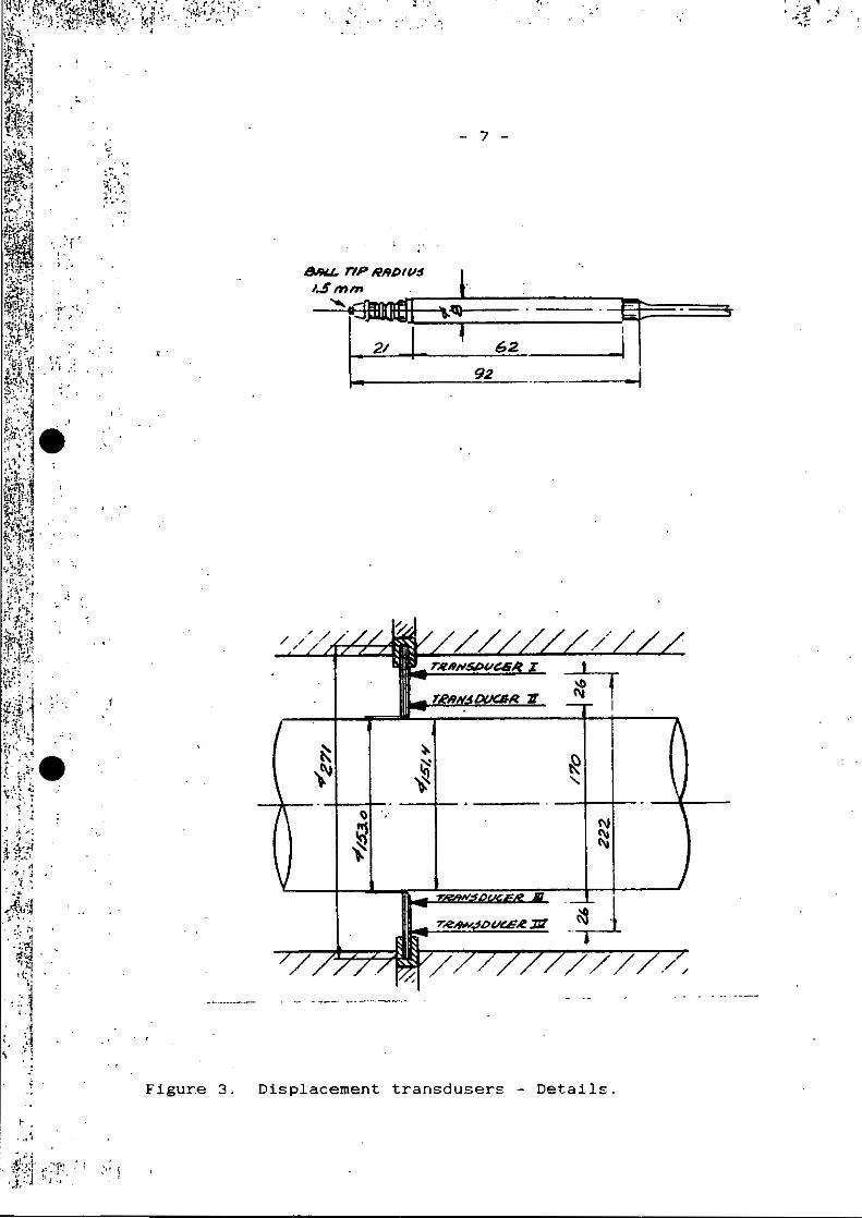
Figure 3. shows the transducers used for deflection measurements, and also indicates placement of these tiansducers (4) on the orifice plate under test.
The DP-cell and the deflection measurement transducers w~re connected to a DATA 6000 data logger. capable of logging more than 2000 samples at high speed to internal memory . fr o m each input channel in parallel, during a test run {approx. 1 minute).

. . . . . ... ·: -:.~·-: ~ . ..-- . . - · . .., - -.;. . . ... ~ · .~· ~ ·,.l;~~~~,~~~~~.;~~~·;~~~-~~ -~ :·, :~~~ . ·~1:·
..----¢=7 ;9/~ $Wl0.LY.
0 I -.3 .!MR.
(},e/;'/t:"S . CdN$rA?1cro.~.
/-\ Figure 2. General arrangement of test rig.
- -~·· ·· ··, ;;;;--·-:-·· - .
01!/P/eG P~T6 DEF~Ec:' Tl'O/V IYEHiV~ENEIYr.
P,e/NTL!J~/ Aorr~
~ .. . :-- .. . .
' • . ,4
.J!, ·I· . ~ . I .,,.,, }' • · .... 1•t ' • ·'!:'•] ,, ' •i . '.I:: !· .! I •
Figur.e 3.
;:i.··.··
··. ~
&9U- rlP lellD/11$
1..Smm
... . :
- 7 -
""8lmef::!E===:==:J~~ 21 62.
92
~ ~
~ N ).~ ~ '
~ (\I
~ ~ ~
/ // ./,,
Displacement t ransdusers - Details.

•r . . .' .
·\·e . ~·~ . . p
. ~i l . 1, ~ .J. f : ... .i.~ ·,
.· j
J. ;
. "~ · . .. . . ' ., .
. I ~ , . : .. . . ~ . '
- 8 -
After each run, data from the data logger was transferred to a Hewlett Packard 9816 series 200 desktop computer . for data processing and presentation of tables and graphs.
A sketch showing the· theoretical deflection form of the orifice plate is shown in Figufe 4. The displacement value Ymax was derived during the test by . linear interpolation under the assumption of flat plate theory.
TESTS PERFORMED
Tests were carried out with a combination of 3 seal rings, each of a different type, and 3 orifice plates with different properties. Figure 5. illustrates how the seal rings fitted into the carrier.
Eacn combination was tested 4 times, twice with increasing d/p ( O - 1000 mbar) and twice with decreasing d / p ( 1000 - o mbar}.
Referring to Figure 2., the following was done before each of the above tests:
.. •• q.•
Buffer tank pressure was set to establish 1000 rnbar across the orifice plate, with Pressure Regulating Valve fully open. Data logger was "armed".
Test run - Increasing method ( 0 - 1000 mbar) : Pressure Regulating Valve was fully closed . Air valve between buffer tank and pipe was fully open . Trigger signal to data logger and opening/closing device on Pressure Regulating Valve .
The data logger now started to collect data . Ahile Regulating Valve was ~lowl~ turning to fully open. closing devise was set to fully open the the valve timespan of the data logging period (approximately The d/p cell signal and the transducer signals were in the data logger me~~ry, for further processing .
Test run - Decreasing .method ( 1000 - o mbar): Pressure Regulating Valve was fully closed.
the Pressure The opening/
within the 1 minute). all stored
Air valve between buffer tank and pipe was fully open. Trigger signal to data ' logger and opening/closing device on Pressure Regulating Valve . Shut of air supply to buffer tank. _
In this case the opening/ closing device was set to open the valve at maximum speed . Whe~ the Pressure Regulating Valve was fully open, the air supply to .the buffer tank was shut of. The pipe pressure started to drop, and the d/p cell sign·a1 reached zero within °the timespan of the data logging period (approximately 1 minute). The d/p cell signal and the transducer signals were all stored in the data logger memory, for further processing .

........ . • ·.r :.
·~~ .. : ~~ !.1 I
'>•
~- . • . • 1 . •
... • .t · ' . . ~. ~ -~
, . ._ I : ' ~ ! . ;, .... . •'} ,, : . . .
. . ' .. . ,-• · :.·-:·;.1 ;t ;,: ~ :·1 -~~-~!:~:.\ . .--~ ·!
- .-.. ; ·. t. ·•• . • '
' . ' ?::.,. .. -! • 1
" , .. e I··•
• 4.
•"' ... ·~- j
I
. ·.~ .• -.~ .; .· ·.; .. '
. ~··-~
,.,
.. i -!
l ' ~! .,
Figure 4 .
Chfice plate before bending
OIRECTCN-..-~-- -'-OF FLO\./
.. a ...
)(
- 9 -
-)C
Orifice plate ofter bending
sensor 2
.... )<
.. • • x
Tube wall
- -~
Principle of plate deflection measurement .

! !~.: -1 - ' , ··~ .. !
~·~~ .j
~J~ -· ""i
'5} :~ ;;· _.
' · 1 H '. .. ~ i
. ·, .···-. : .
' '.I
. -· •I
'
·.
~.·
- 1 0 -
ORI ACE PLATE
TEFLON SEAL ( SEAL No 3 )
ORIFICE PLATE
METAL SEAL ( SEAL No 1 >.
ORIFICE PLATE
METAL SEAL ( SEAL No 2 )
Fi gure 5 . Differ e nt seal r i ng a r rang ements .
·1 DIRECTION OF FLOW
DIRECTION OF
FLOW
J DIRECTION
OF FLOW

<.
~· · \- i '. .. .a !! ' _, ,r. •
~ · ~~ ,,
.. • • >
... . _. '
~· .;; • • 4~ ,;.- . ~
l
_; . .a ~ .. ., .
~.'. •( ~~~ -: -~ .· ' ' ;·
:. . .
H!• ... . ·' : . '·· .
}::: :l ·:Jt.:; :·; :.
. ·
RESULTS
...... h -. '"'1 •··· ' . - .,, . " . . ~ .... ~ .. :~ .. :.
· .. ~·f:.' .. •:·
"
- 11 -
Three different orifice plates where tested {ESAS-H076 6.177mm thick, ESAS-M075 6.197mm ·thick , DANIEL-95685 6.47Srnm thick} . each of them mounted in three different s ea l rings, (Metal - 3165/S 256rnm l/D, Metal-3165/S 224mm l/D and Teflon 224mm I/D, all from DANIEL) .
Some examples of the graphs of orifice plate deflection , measured and ca lculated according to Jepson and Chipchase. are present~d in the Figures 6, 7, 8 , 9 and 10.
.. ~
• .. J
ii ~ c: 0 .. " • -~ .. a
Figure 6.
Ch r i st i an Mi ch e 1 sen Inst i tut e , 1 7 Nov 198 6 Orifice plate deflect ton vs. dif ferential pressure, Run no. 1. 11
B.15 v MAXIMUM IJlSPLH ~(MENT
B.H <?. SERL ~OH PRE ISS!ON.
/ ~
v v
.. ,. • • o
1 . 41
v /
~ / ------ --/ ---i---
' v ~ / ---v _v-
/
!~ i.---' I .---i .. ·-· 4H---:. .... ... ,, .---. .. ·- I -
l.l5
1.311
1.11
.. ,. 1 . 15
1.11
1 ; 115
....
Measured deflection of M076-ESAS plate mounted in metal seal 316 S / S, 256mrn I / D. (Run 1 . 11 }

: " !
~ ...
: : ; . :
. l
• J ' .
., f
. -'
I'
•
· •!
>' ..... ·.
- 12 -·
Ch r i st I an M I ch e 1 sen Inst t tut e , 1 7 Nov 1 9 8 6 Orifice plate deflection vs . differential pressure, Run no. I. II
9.~9 v PLAH DEF LE ::;TION.
9 , 4' oCAV lLRT£[ DEF'L£ '°TION .
~ •.n .. ;
i ~ c D .. .. •
.. ,. 9.IS
'·" 8.15
8 . 18
•.m
8.89
~ ~
~ .,.....
.....;:
~ .,--
~ V'"
,h ~-
I~ ~ ... ~··
... . "' . '" ., .. ,,. -.. . ·- ••a • Dlff•r•ntlal pr•••ur• In •lll t bar
Figure 7. Mea sured and c alc ulated defiec tion of ~076-ESAS plate mounted in metal sea l 3 16 S/S , 256rnm I / D. (Run 1. 11) "
.. .. .. .. ~
c D -.. " ..
Christian Mi chelsen Institute, 19 Nov 1986 Orif ice plate de fl ection vs. di fferential pressure, Run no . 2 . 11
8 . 51 v PL PH DEF'LE p:TI ON.
o CRLC LJLATCll DEF'U' '"TION. 8 . 4'
e.n
-~ ~
8.H
__...-;;. ~~
~ v
__/
8 . ZI
~ c.,.....--/
~ ~.,
e. u
•••• • . es
~ :t;"
HI • A----S• ~.,-, .. 10,.........--,mi-. - ·- .,_ 8.88
·, .. . . '
F i gure a . ·Measured and ca l c ulated deflection of M0 76-ESAS p late mou nted in meta l s ea l 3 16 S/S , 244mm I / D . (Run 2. 11)

~ . ' . ; . i
~ .. -. . ] -:' - ·~
-· ~
. ·' ··~
. /~~ ··; . ..; ., • '.t" ·'.!J ) i • • \ .
., .. . '·· · !- .
• .. • .. a
c 0 .. u • ...
&
. · - 13 - · ·h ·:· ·.
Christian Michelsen Inst i tute, 22 Aug 198G . Orifice plate deflection vs. differential pressure , Run no. 3 . 11 ....
v PLATE DEF'LE f:TY6N:'
•••• oCRLC ULRTEI DEFLr "TION .
•••• 1.11
1 . 11 /
~ vo ./ I.IS
~ v ~
v ./
~ ~ -.......-::: v-
I.,/ ~ o i ua-. ilr---?~11-. .. -.-I . .-, .. ...
.... • ••• 1 . 11
'·" I . A
F igure 9 . Measured and c alc ulate d def l ection of M076-ESAS pla te mo u n t e d in Teflon s eal , 22~mm I / D. (R un 3. 11 )
.. ~
• .. • • ---• ~ c ! .. u ! ... d
Christian Michelsen Institute, 18 Nov 1986 Or i f ice plate deflection vs. differential pressure, Run no. l.31 .. ,.
v PLf' iE DEF'LE ,. TION ,
._., o CRLC: LJLATEC DEf'U: t:TION .
•••• 1.n
' e.Ja
.9-e.n
.. ,. e. u
•••• .. ., ••••
~ ........
_,
~ .......... ~ l___.....
L,...oo' ~
L--
~ ---__......-: t::-L.---
~.--__...... 1 •--Z•.--l• ... . .. . ... ,. .. .. ·- " II
Dtffaren\ l a l praaaur• tn allllba~ ·---- ---- - ---- - - ·- ----- ----------Figu~e 10 . Measured and calc ulated d e f l ec t ion of 95658 - DANIEL
pla te mounted i n metal s e a l 3 16 S / S 256 mm I/D( Runl. 13)
i'.
..; .. ..

\r . .' :~ :
•. t . •
·'
. I
· .. . . ·
· I
·'
Table 2 .
RESULTS COMPARISON OF ACTUAL DEFLECTION AGAINST THEORETICAL DEFLECTION
ORIFICE PLATE SIAL RING
ESAS (6.177 THICK) ESAS (6.197 THICK) DANIELS(6.47S THICK
1, MITAL VERY CLOSE TO 20% LESS THAN 20% LESS THAN 298 MM l/D THEORETICAL THEORETICAL THEORETICAL
DEFLECTION DEFLECTION DEFLECTION
2. MITAL CLOSE TO . 33% LESS THAN 40% LESS THAN 224 MM l/D THEORmCAL THEORETICAL THEORETICAL
DEFLECTION DEFLECTION DEFLECTION (± 10%)
3. TEFLON 16% GREATER 15% GREATER CLOSE TO 224 MM l/D THAN THEORETICAL THAN THEORETICAL THEORETICAL
DEFLECTION DEFLECTION AT 1000 MILLIBAR, 15% GREATER AT 600 MILLIBAR

-~- ·' ;f .~~\,· .. ~ ~ '"c' • • . , .4; ·~ I ·~ . '
: ~ .
. ·1
j Jl
:I .
'. ":-/~ -.1~ ~ ··-· I .• •· -~
- 15 -
CONCLUSION
From the results of th~ tests it couid be seen that each seal ring/orifice plate combination performed in a different way. Of the three seal rings however. the following comments can be made:
Seal Ring 1. (Met~l 256mm I/D) It was the only seai. ring which matched the orifice plate carrier.
Seal Ring 2. (Metal 224mm I/D) The insid~ diameter of the seal ring protruded into the carrier bore. giving additional support to the orifice plates. The results obtained from this seal ring were repeatable. although significant seal movement was experienced at low DP, owing to use of old "O''-rings.
Seal Ring 3. (Teflon 224mm I/D) The inside diameter of the seal ring protruded into the carrier bor~. initially providing additional support to the orifice plate. On repeated tests this support was much less evident. due the plastic deformation of the Teflon.
Whilst the results from Seal Ring 2 and 3 are most interesting, such seals would not have been used in a similar offshore metering station. because their inside diameter protrude into the bore of the carrier.
In conclusion however, the results of the tests (with particular reference to Seal Ring 1.) have established the following:
1. The Jepson· and Chipchase formula for orifice plate . deflection under high differential pressure. will give a worst case result if the orifice plate is used with a me~al seal ring.
2. Increases. in the thickness of standard orifice plates do not significantly reduce orifice plate deflection.
3. As DP increases (max 1000 mbar) the Jepson and Chipchase formula will increasingly predict a deflection value in excess of the actual value.
4. The use of Teflon seal rings will generally give less overall plate displacement (i.e. seal ring + orifice plate), but may give an orifice plate deflection 153 greater than that calculated by using the Jepson and Chipchase formula .

.. '!}!~;; .. . .;
._. :. -
,.. ··:. .. ! ~ 'l; •
... Ji . . -~ ·, -'"'· I
..... ~1~ . ··'I
··. ·~
' . ':--~~:1
.. ~· .· "
·.:
... ... . !,·.:
' • -= - • : ~ •
'• 7 ;:~ ·~ ~. ' I •
-~.
"
- 16 -
SUMMING UP
Al though the tests described in this paper t-1ere mo ti vate:d by operational needs, the ~onsequence of our findings have probably more impact in the future design of new meter stations.
If for example authority ·approval was obtained to operate meter stations at DP levels up to say 1000 mbar. the potential savings for the industry could be enormous in terms of:
Weight Savings
Equip. Cost Savings
Operating Cost Savings
Spares Cost Savings
ACKNOWLEDGEMENT
The authors of this paper would like to express their sincere thanks to the following parties for their assistance during the execution of the project:
Dr. Bob Peters G. G. Brown M. Marshall
DANIEL Industries MOBIL Consultant

. . . .~~~ ,') ..
·. - ~ -i.. ,
,. f· >1. ;
1 '.¥. . ' . ·-~
I . • \ ·•
.. . .
·:~ .. . -.. ... .. . . . ,; '.
- 17 -
.. ·.~ ~ . ~· • '
REFERENCES
1 . International Standard ISO 5167 Rev. 1980 .
2 .
3 .
4.
Measurement of fiuid flow by means of nozzles and venturi tubes ·inserted in cross-section cqnduits running full.
P . Jepson R. Chipchase
orifice plates , circular
..Effect •:>f Plate Buckling on Orifice Meter Accuracy" Journal Mechanical ·Engineering Science, Vol 17 No 6 1975.
Norwegian Petroleum Directorate 1984 Regulation for fiscai measurement of gas produced in internal waters, in Norwegian territorial waters and in the parts of the Norwegian Continental Shelf which subject to Norwegian sovereignty.
Audun Haugs et al; "Orifice Plate Deflection Measurement" Final Report . CMI - No 86120~-1~ 1906 .