Audio + Video Standard Surround Preamp/ · PDF fileAudio + Video Standard Surround...
32
Audio + Video Standard Surround Preamp/Processor Instructions for Use, v 98.3 Owner’s Reference
Transcript of Audio + Video Standard Surround Preamp/ · PDF fileAudio + Video Standard Surround...

Audio + Video StandardSurround
Preamp/Processor
Instructions for Use, v 98.3
Owner’s Reference

Audio + Video StandardSurround Preamp/Processor
CONTENTS
Krell® Industries, Inc.
45 Connair Road
Orange, CT 06477-3650 USA
TEL 203-799-9954
FAX 203-799-9796
E-MAIL krell @ krellonli ,ne.com
WEB SITE ~.krellonline.com
INTRODUCTION
UNPACKING
PLACEMENT
FRONT PANELDESCRIPTION
BACK PANELDESCRIPTION
CONNECTING THE AUDIO + VIDEOSTANDARD TO YOUR SYSTEM
REMOTE CONTROLDESCRIPTION
SYSTEM CONFIGURATION
OPERATION
SAVING, RECALLING, ANDCLEARING CONFIGURATIONSET-rINGS
WARRANTY
RETURN AUTHORIZATIONPROCEDURE
SPECIFICATIONS
3
3
4
5
9
12
13
18
26
29
3O
31
Back Cover
ILLUSTRATIONS
Figure 1 FRONT PANEL
Figure 2 BACK PANEL
Figure 3 REMOTE CONTROL
Page
8
11
16
998 by KRELL® Industries, Inc. All rights reserved P/N 1960101900389

CE Marking
This ’product complies with the EMC direc-tive (89/336/EEC) and the low-voltage direc-tive (73/23/EEC).
¯IntroducbonThank you for your purchase of the Krell®
Audio + Video Standard. To obtain the bestperformance from your Audio + VideoStandard surround preamp/processor, paycareful attention to its placement, installa-tion, and operation. A thorough understand-ing of these details will help insure satisfac-tory operation andlong life for the Audio +Video Standard and related’ system compo-nents. ~
THERE ARE NO USER-SERVICEABLEPARTS INSIDE ANY KRELL® PRODUCT.
Please contact your authorized dealer,distributor, or KrelP, if you have any ques-tions not addressed in this referencemanual.
Unpacking
1. Open the box and remove the top layer offoam. You will see these items:
1 Audio + Video Standard1 AC power cord1 Audio + Video remote control4 AAA batteries1 T-10 Torx wrench1 packet containing an introductory
letter from Dan D’Agostino, C.E.O.,the Owner’s Reference, and theWarranty Registration Card
NoteIf any of these items are not included, pleasecontact your authorized Krell® dealer or dis-tributor immediately for assistance.
Carefully remove the unit and acces-sories from the box. Remove the protec-tive plastic wrap from the unit.
NoteSave all packing materials, ff you must shipyour Audio + Video Standard in the future,repack the unit in its original packaging toprevent transit damage.
KRELL® Audio + Video Standard English Page 3 of 32

Placement
WARNINGThe surround preamp/processor must notbe located where it could be exposed to drip-ping or splashin~luids.
IMPORTANTThe ventilation grids and cooling fan on thetop of the Audio + Video Standard need tobe unobstructed at all times during opera-tion. Do not place flammable material ontop of or beneath the Audio + VideoStandard. For installations inside cabinet04,make sure the Audio ÷ Video Standard hasadequate air circulation. Contact your dealer,distributor or Krell~ for further information.
Before you install the Audio + VideoStandard. into your system, review thefollowing guidelines to choose the opti-mum location for placement. This willhelp ensure a clean, trouble-free installa-tion. For the dimensions of the Audio +Video Standard, see Specifications onback cover.
Place the Audio + Video Standard surroundpreamp/processor on a firm level surfaceaway from dirt or moisture. A minimum spac-ing of three inches must exist between theAudio + Video Standard and surroundingcomponents to ensure proper ventilation.
AC POWER GUIDELINES
WARNINGDo not remove or bypass the ground pinon the end of the AC cord. This may causeRFI (radio frequency interference) to induced into your playback system.
The Audio + Video Standard has superb reg-ulation and does not require a dedicated ACcircuit. Avoid connections through extensioncords or multiple AC adapters. High quality,15 ampere, grounded AC strips are accept-able. High quality AC line conditioners or fil-ters may be used if they are grounded.
Page 4 of 32 English KRELL® Audio + Video Standard
Front PanelDescriptionSee Figure 1 on page 8
1 TapeA tape monitor al!~ws you to compare theoutput from your a~log tape recorder to theoriginal source while making a recording.After selecting a source for recording (B1,$1-$5), press the tape button to togglebetween the tape recorder output (LED illu-minated) and the input source (LED not illu-minated).
2 Analog InThe Analog In button activates the analoginput and cycles .through the six analogaudio inputs. B1 is a balanced input via XLRconnectors. $1-$5 are single-ended inputsvia RCA connectors.
3 Digital InThe Digital In button activates the digitalinput and cycles through the six digital audioinputs (C1, C2, T1, T2, XLR, and RF). Themain display will show RF IN when the RFinput for Dolby Digital (AC-3) is selected.
C1 and C2 are coaxial inputs via RCAconnectors.T1 and T2 are TosLinkTM inputs.
XLR is an AES/EBU connection.RF is available via RCA or BNC connec-tors. There is no front panel LED for thisdigital input.
4 Main Display ,The main display provides status.messagesfor a variety of Audio + Video Standard oper-ations.
5 CompositeThe composite video input button cyclesthrough the four composite video inputs.
6 S-VideoThe S-video input button cycles through thefour S-video inputs.
7 Volume Control KnobThe volume control knob adjusts the outputlevel for the entire system as well as individ-ual levels for the center speaker, side speak-ers, rear speakers, and subwoofers. The vol-ume control knob normally adjusts the mas-
. ter volume as indicated by the LED illuminat-ed above the master button (19). Thechange in volume is indicated in the maindisplay and also on-screen. Adjustments tothe center speaker, side speakers, rearspeakers, and subwoofers are made bypressing the corresponding individual chan-nel volume buttons (20) and rotating the vol-ume control knob to the desired setting. Themaster volume control has a numericalrange from 0 to 152 with 89 being the Dolbyreference. The center speaker, side speak-ers, rear speakers, and subwoofer volumetrim have a range of __.12 dB.
8 Power ButtonThe powerbutton toggles the Audio + VideoStandard from standby to operate and alsoswitches the 12 VDC output between on andoff.
9 Power LEDThe power LED illuminates when the. rearpanel main power switch [see Figure 2 (38)on page 11] is placed in the on position.During remote control operation, the powerLED will flash, indicating the Audio + VideoStandard is receiving remote control com-mands.
KNELL® Audio + Video Standard English Page 5 of 32

10-16 Audio Mode ButtonsThe five buttons (10, 13, 14, 15, and 16)select one of the Audio + Video Standard’saudio modes.
The Audio + Vid~.o Standard automaticallyselects which di~al decodingformat to use,based on the input signal it receives.
When a silent digital signal .is present, theAudio+Video Standard will automaticallymute its output until program materialresumes and the Audio+Video Standardidentifies the correct processing mode. Thisoccurs while changing laser, DVD or com-pact discs, and between tracks on a cd.
Mute protects your syste ,m by preventing theAudio + Video ~Standard from playing backdigital data in an incorrect format. If the Audio+ Video Standard is going to be used as adigital to analog converter for music play-back, this muting may seem awkwardbecause the beginning of each track may beaffected. You can change the format auto-sensing to eliminate this muting, if you wish.To do so, switch the unit into standby. Pressthe DTS button (13) on the front panel andswitch the Audio+Video Standard out ofstandby to power on (operate). This will dis-able the automatic muting feature of theAudio+Video Standard and will alter the wayin which the automatic format sensing oper-ates. For best results, select DTS prior to lis-tening to any DTS encoded material and becareful to select the proper format for eachpiece of softWare played through the. digitalinputs.
To re-engage the automatic muting feature,switch the Audio+Video Standard into stand-by and toggle the main power switch (38) the rear panel to the off position. When. yourestart your Audio + Video Standard, the
automatic muting feature will be active. Besure to turn all amplifiers off when switchingthe main power switch on and off.
10 Dolby Digital engages Dolby Digital(AC-3) processing for use with DolbyDigital (AC-3) encoded source material.The Audio + Video Standard automati-cally switches to Dolby Digital (AC-3) pro-cessing upon receiving a Dolby Digital(AC-3) encoded signal. No user interven-tion is required after the appropriate digi-tal input is selected and connected.
Dolby Pro Logic engages Dolby ProLogic circuitry for use with all Dolby sur-round processing encoded material. Thisincludes laser discs, videotapes, televi-sion broadcasts, and compact discs.
11 The Dolby Digital LED is lit and theDolby Pro Logic LED (12) is not lit whenthe Audio+ Video Standard is in theDolby Digital (AC-3) decoding mode.When both the Dolby Digital LED and theDolby Pro Logic LED are lit, the Audio +Video Standard is decoding a DolbyDigital (AC-3) encoded Dolby Pro Logicsignal.
12 The Dolby Pro Logic LED is lit andthe Dolby Digital LED (11) is not lit whenthe Audio+ Video Standard is in theDolby Pro Logic decoding, mode. Whenboth the Dolby Digital LED and the DolbyPro Logic LED are lit, the Audio + VideoStandard is decoding a Dolby Digital(AC-3).encoded Dolby Pro Logic Signal.
13 DTS engages DTS digital surroundprocessing for use with DTS encodedsource material. The Audio + Video$tandard automatically switches to DTSprocessing upon receiving a DTS signal.No user intervention is required after the
Page 6 of 32 English KRELL® Audio + Video Standard

appropriate digital input is selected andconnected.
14 Music engages Krell Music SurroundTM
circuitry for use with stereo recordings.
15 Mono is for use with monophonicrecordings. This provides monaural out-put from the ~nter speaker and sub-woofer(s) only.~lf the system does notinclude a center speaker, the monauralsignal is split between theleft and rightspeakers.
16 Preamp disengages all surroundprocessing circuitry for use with stereorecordings. When fed an analog source,the Audio + Video Standard functions asa pure Class Ai~ high resolution, analogpreamplifier. For digita, I sources, theAudio + Vide£ Standard employs 24-bit,custom KrelP-written, digital-to-analogconversion software before being sent tothe analog preamplifier stage.
17 Recall ButtonThis button saves and recalls system config-uration settings..
18 Infrared SensorThe infrared sensor receives commandsfrom the Audio + Video Standard remotecontrol. For proper remote control operation,make sure the infrared sensor is clear of anyobstructions.
19-21 Volume Control Buttons
The following six buttons select one of theAudio + Video Standard’s volume chant~els:
19 Master Volume ButtonWhen the LED above this button is illu-minated, the volume control knob (7)affects the entire system equally. The vol-
ume adjustment is indicated in the maindisplay and also on-screen.
20 Individual ChannelVolumeTrimWhen the LED above any of these but-tons is illuminated, the volume controlknob (7) changes the level of the select-ed channel. These new changes willclear when a new input mode is selected.The volume control knob reverts back tocontrolling the default level, Master, afterfour seconds of inactivity.
21 Balance Button(Preamp mode only)When the LEE) above this button is illu-minated, the volume control knob (7)affects the left-to-right balance of the sys-tem. The center position is indicated byCNTR in the main display. Balance may beadjusted in 1 dB increments up to 9 dB.The next adjustment mutes either chan-nel, indicated by ROFF or LOFF for the rightchannel and left channel respectively.The on-screen representation for bal-ance is graphical:
L ......... : ......... R
The center position is indicated by twovertical dots, Each dB of adjustment isrepresented by one individual dot.Moving the cursor so that it covers the Lindicates a completely muted right chan-nel. Conversely, positioning the cursor sothat it covers the R indicates a complete-ly muted-left channel. The volume controlknob (7) reverts back to controlling thedefault level, Master, after four secondsof inactivity.
KRELL® Audio + Video Standard English Page 7 of 32

FIGURE 1 AUDIO + VIDEO STANDARD FRONT PANEL
2 3 4 6 5
9
11
1 Tape
2 Analog ~’~
3 Digital In
4 Main Display
5 Composite
6 S-Video
7 Volume Control Knob
10 1312
15 1714 16 .. 18 19
8 Power Button
9 Powe~ LED
10 Dolby Audio Mode Button
11 Dolby Digital (AC-3) Audio Mode LED
12 Dolby Pro Logic Audio Mode LED
13 DTS Audio Mode Button
14 Music Audio Mode Button
2O 21
15 Mono Audio Mode Button
16 Preamp Audio Mode Button
17 Recall Button
18 Infrared Sensor
19 Master Volume Button
20 Individual Channel Volume Buttons
21 Balance Button

Back PanelDescriptionSee Figure 2 on page 11
22 Balanced Channel OutputsThe Audio + Vid~p Standard is equippedwith nine channel ~utputs. All nine channelsare equipped with balanced outputs via XLRconnectors as well as single-ended connec-tors (30). The nine channel outputs are forthe center, left, right, left and right side, leftand right rear, and two subwoofer outputs(labeled Sub1, Sub2).
The XLR pin configurations are as follows:
Pin 1" Shield (g~round)Pin2: Non-inverting (0,°,)Pin3: InvertiNg (180°)
23 Analog Tape InputThe Audio + Video Standard is equippedwith one single-ended tape input.
24 Balanced Analog InputsThe Audio + Video Standard is equippedwith one balanced input (labeled B1) viaXLR connectors.
The XLR pin configurations are as follows:
Pin 1: Shield (ground)Pin2: Non-inverting (0°)Pin3: Inverting (180°)
25 Single-Ended Analog InputsThe Audio + Video Standard is equippedwith five single-ended in puts (labeled S’1-$5)via RCA connectors.
26 RF InputsThe Audio + Video Standard is equipped withan RF input for use with the Dolby Digital(AC-3) RF output of a laser disc player.
Connections are via RCA or BNC coaxialdigital cable.
27 S-Video InputsThe Audio + Video Standard is equippedwith four S-video inputs (labeled 1-4).
28 S-Video OutputsThe Audio + Video Standard is equippedwith three S-video outputs. The main S-videooutput (labeled on screen) includes on-screen graphics. For dubbing purposes, thesecond and third S-video outputs do notinclude on-screen graphics.
29 Infrared Remote SensorsThe Audio + Video Standard is equippedwith an additional infrared sensor and a malebaseband RC-5 remote input for custominstallations.
30 Single-Ended Channel OutputsThe Audio + Video Standard is equippedwith nine channel outputs. All nine channelsare equipped with single-ended outputs viaRCA connectors as well as balanced con-nectors (22). The nine channel outputs arefor the center, left, right, left and right side,left and right rear, and two subwoofer out-puts (labeled Sub1, Sub2).
31 Digital Audio OutputsThe Audio + Video Standard is equippedwith two digital audio outputs in the followingformats:
One coaxial via RCA connectorOne TosLinkTM
32 Tape OutputsThe Audio + Video Standard is equippedwith three analog tape outputs. Two are foruse with video sources (labeled VCR1,VCR2), and.the third is for use with an audiotape deck (labeled tape).
KRELL® Audio + Video Standard English Page 9 of 32
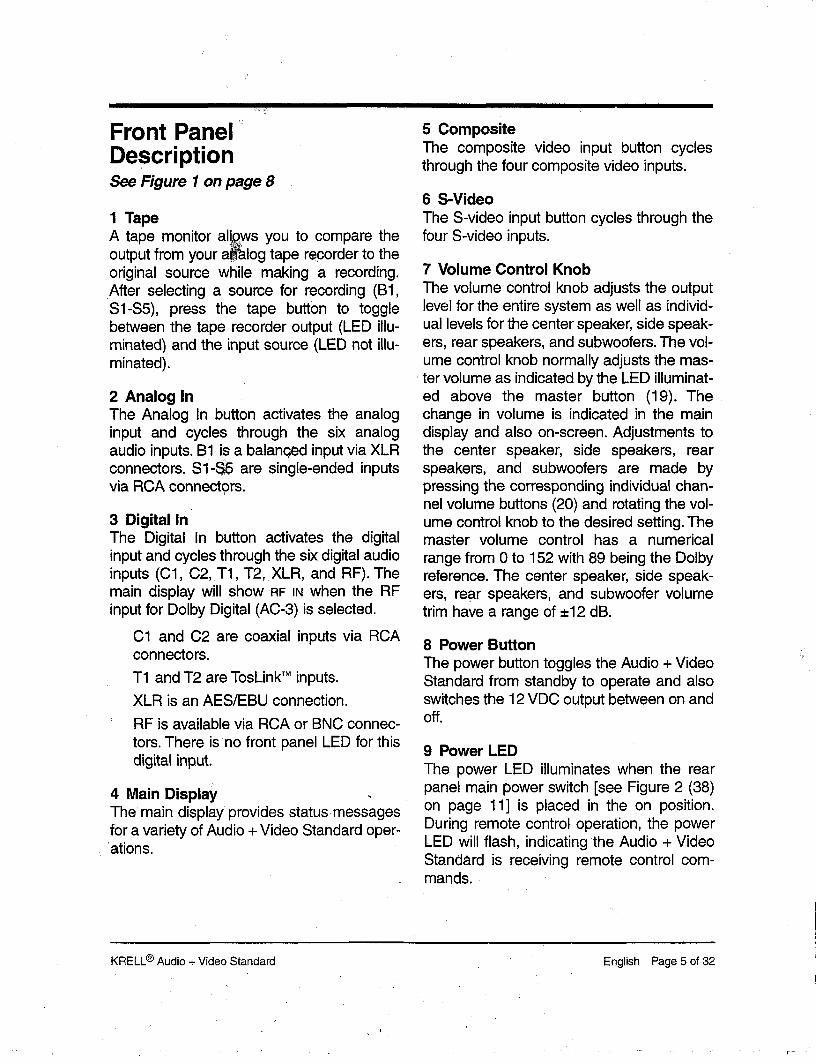
33 Digital Audio InputsThe Audio + Video Standard is equippedwith five digital audio inputs in the followingformats:
Two coaxial via RCA connectorsTwo TosLinkTM
One AES/EBU vixen XLR connector
34 Composite Video InputsThe Audio + Video Standard is equippedwith four RCA composite video inputs(labeled 1-4).
35 Composite Video OutputsThe Audio + Video Standard is equippedwith three RCA composite video outputs.The main composite video output (labeledon screen) includes on-screen;graphics. Fordubbing purposes, ~the second and thirdcomposite video outputs do not include on-screen graphics.
36 Composite Video (BNC) Input/OutputThe Audio + Video Standard includes onecomposite video input and one compositevideo output via BNC connectors. These
ports are electrically identical to the RCAcomposite video inputs (34) and, outputs(35).
NoteYou may simultaneously use both RCA andBNC outputs, but only one of the inputs.
37 IEC Power ConnectorThe Audio + Video Standard is equippedwith a standard female IEC power connec-tor.
38 Main Power SwitchToggles the Audio + Video Standard betweenoff and standby.
39 12 VDC OutputActivated by the front panel power button (8),the 12 VDC output sends a 12-volt poweron/off signal to other Krell® components, aswell as to other devices that incorporate a12-volt power on/off trigger input. This allowsfor remote turning on/off of other compo-nents when the Audio + Video Standard isdowered on.
Page 10 of 32 English KRELL® Audio + Video Standard

FIGURE 2 AUDIO +VIDEO STANDARD BACK PANEL
22 30 23 24 25 26 27 28 36 39 29
22
22 Balanced Ch~l Outputs
23 Analog Tape ~nput
24 Balanced Analog Inputs
25 Single-Ended Analog Inputs
26 Dolby Digital Inputs
27 S-Video Inputs
32 31 33 34 35
S-Vid oO uts29 In~rared Remote Sensors
30 Single-Ended Channel Outputs
31 Digital Audio Outputs
32 Tape Outputs
33 Digital Audio Inputs
34 Composite Video Inputs
35 Composite Video Outputs
36 Cdmposite Video (BNC) Input/Output
37 IEC Power Connector
38 Main Power Switch
39 12 VDC Output

Connecting theAudio + Video Standardto Your System
WARNINGWhen making conn~ions to thi.s compo-nent or any other, make sure the poweramplifier is off and the preamplifier is in themute or stand-by mode. Make sure allcable terminations are of the highest qual-ity, free from frayed ends, shorts, or coldsolder joints.
For analog audio sources, connect theleft and right outputs of your source com-ponents to the inputs on ,the Audio +Video Standard. The Addio + VideoStandard is equipped with six single-ended analog audio inputs ($1-$5 andtape) via RCA connectors and one bal-anced analog audio input (B1) via XLR connector.
2. For digital audio sources, connect thedigital audio output of your source com-ponents to the digital inputs on the Audio +Video Standard. The Audio + VideoStandard is equipped with five digitalinputs: two coaxial inputs via RCA con-nectors, two TosLinkTM optical connec-tions, and one AES/EBU via an XLRconnector. For Dolby Digital (AC-3) sur-round processing, connect the RF outputof a laser disc player to one of the RFinputs.
NoteFor source units that are equipped with bothdigital and analog audio outputs, higher per-formance will generally result when connect-ing source units to the Audio + Video Standardusing a digital audio output.
Connect the video outputs of your videosources to the video inputs on the Audio+ Video Standard.
The Audio + Video Standard is equippedwith four S-video inputs and four compositevideo inputs. S-video cables transmit thecolor and luminance components of thevideo signal separately. This separation isperformed by the comb filter within thesource unit. If the source unit’s comb filter issuperior to the one within the video monitor,S-video connections should be used.Otherwise, a composite video connectionshould be used.
NotesS-video cables should not be used forlengths greater than 20 feet, for optimumperformance.
The Audio + Video Standard does not con-vert video signal formats, Le., an S-videoinput signal is output as an S-video signalThe same condition holds true for a com-posite video signal
The Audio + Video Standard is equippedwith three S-video outputs and three com-posite video outputs. The main S-video out-put (28) and composite video output (35)include on-screen graphics. The compositevideo 1 output also has a parallel BNC con-nector. For dubbing purposes, the secondand third video outputs do not include on-screen graphics. These outputs may be con-nected to the video inputs of your videorecorders or to:additional video monitors.
Connect the outputs of the Audio + VideoStandard to the input(s) of your poweramplifier(s).
Page 12 of 32 English KRELL® Audio + Video Standard

Connect the outputs of the Audio + VideoStandard to the input(s) of your poweramplifier(s).
The Audio + Video Standard has balancedoutputs via XLR connectors and single-ended outputs ~,, RCA connectors. Bothoutputs are act~e at all times, allowingsimultaneous connection to separate ampli-fiers. Only one of these output formatsshould be connected to a single amplifier.
NoteWhen connecting inputs or outputs to theAudio + Video Standard, remember that thebalanced connections will have 6 dB moregain than the single-ended connections. Iflevel matching becomes difficult in yourinstallation, keep this spe~’fication in mind.
5. Plug the AC cord into the receptacle onthe back of the Audio + Video Standard.Plug the remaining end into the AC wallreceptacle. Toggle the main powerswitch (38) to the up position. The redpower LED (9) will illuminate, and themain display (4) will show AC-3 for threeseconds. The Audio + Video Standard isnow ready for operation.
Press either the front panel power button(8) or the remote control power button[see Figure 3 (44) on page 15]. The wordWAIT will appear in the main display andthe initializing message will appear on-screen. To configure the Audio + VideoStandard for operation, see SystemConfiguration on page 18.
Remote ControlDescriptionSee Figure 3 on page 16
40 Analog Audio Input ButtonsThese buttons select the analog audiosource. B1 is a balanced input via XLR con-.nectors while $1-$5 are single ended inputsvia RCA connectors. The tape button allowsaccess to an analog tape recorder.
41 Digital Audio Input ButtonsThese buttons select the digital audiosource. C1 and C2 are coaxial inputs viaRCA connectors, T1 and T2 are TosLinkTM
inputs, XLR is an AES/EBU connection, andRF is available via RCA or BNC connectors.
42 Processing Mode ButtonsThe following six buttons select one of theAudio + Video Standard’s processingmodes. FCN, the function button, is reservedfor future use.
The Audio + Video Standard automaticallyselects which digital decoding format to use,based on the input signal it receives.
When a silent digital signal is present, theAudio +Video Standard will automaticallymute its output until program materialresumes and the Audio +Video Standardidentifies the correct processing mode. Thisoccurs while changing laser, DVD or com-pact discs, and between tracks on a cd.
Mute protects your system by preventing theAudio + Video Standard from playing backdigital data in an incorrect format. If theAudio + Video Standard is going to be usedas-a digital to analog converter for musicplayback, this muting may seem awkwardbecause the beginning of each track may beaffected. You can change the format auto-
KRELL® Audio + Video Standard English Page 13 of 32

sensing to eliminate this muting, if you wish.To do so, switch the unit into standby. Pressthe DTS button (13) on the front panel andswitch the Audio+Video Standard out ofstandby to power on (operate). This will dis-able the automatic muting feature of theAudio+Video Stan,~ard and will alter the wayin which the automatic format,sensing oper-ates. For best results, select DTS prior to lis-tening to any DTS encoded material and becareful to select the proper format for eachpiece of software played through the digitalinputs.
To re-engage the automatic muting feature,switch the Audio+Video Standard into stand-by and toggle the main power switch (38) the rear panel to the off position. When yourestart your Audio + Video Standard, theautomatic mutin~ feature will be active. Besure to turn all amplifiers off when switchingthe main power switch on and off.
Dolby Digital engages Dolby Digital(AC-3) processing for use with DolbyDigital (AC-3) encoded source material.The Audio + Video’ Standard automati-cally switches to Dolby Digital (AC-3) pro-cessing upon receiving a Dolby Digital(AC-3) encoded signal. No user interven-tion is required after the appropriate digi-tal input is selected and connected.
Dolby Pro Logic engages Dolby ProLogic circuitry for use with all Dolby sur-round processing encoded material. Thisincludes laser discs, videotapes, televi-sion broadcasts, and compact discs.
DTS engages DTS digital surround pro-cessing for use with DTS encodedsource material. The Audio + VideoStandard automatically switches to DTSprocessing upon receiving a DTS signal.No user intervention is required after the
appropriate digital input is selected andconnected.
Music engages Krell Music SurroundT"circuitry for use with stereo recordings.
Mono is for use with monophonicrecordings. This provides monaural out-put from the center speaker and sub-woofer(s) only. If the system does notinclude a center speaker, the monauralsignal is split between the left and rightspeakers.
Prearnp disengages all surround pro-cessing circuitry for use with stereorecordings. When fed an analog source,the Audio + Video Standard functions asa pure Class A, high resolution, analogpreamplifier. For digital sources, theAudio + Video Standard employs 24-bit,custom Krell®-written, digital-to-analogconversion software before being sent tothe analog preamplifier stage.
43 Levels ButtonsThese buttons select one of the Audio +Video Standard’s volume channels.
Master selects all channels for system-wide volume control.
Balance (Preamp Mode Only) adjuststhe left-to-right balance of the system.
Mute interrupts any audio signal tosource equipment.
44 Power ButtonThe power button toggles the Audio + VideoStandard from standby to operate.
45 Vol Down/Vol Up.ButtonsThe-vol down and vol up buttons control thevolume for either the entire system or for an
Page 14 of 32 English KRELL® Audio + Video Standard

individual channel, a~: selected by the levelsbuttons (4,3).
46 Amplifier ButtonsThe power and meter buttons operate Krell®amplifiers.
47 System Button~These buttons select a preassigned videoinput. Once a video in put is assigned, it maythen be linked to a specific audio input andsurround mode. For details on this assigningand linking procedure, see Direct AccessRemote Control System Programming onpage 24.
48 Video ButtonsThese buttons select the video source. CV1 -CV4 are composite video inj~uts, and SV1-SV4 are S-video in.puts.
49 Enter ButtonThis button inputs on-screen menu selec-tions (functions only in the menu mode).
50 Scroll ButtonsThese four buttons scroll on-screen menuoptions, and also are used for volume con-trol.
51 Menu ButtonThis button accesses, the on-screen menufunctions.
52 Previous ButtonThis button escapes or ends certainscreen menu operations.
on-
KRELL® Audio .- Video Standard English Page 15 of 32
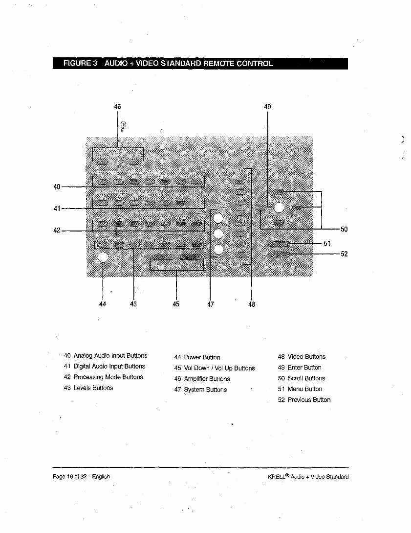
FIGURE 3 AUDIO + VIDEO STANDARD REMOTE CONTROL
46 49
4O
41
42 50
52
44 43 45 47 48
40 Analog Audio input Buttons
41 Digital Audio Input Buttons
42 Processing Mode Buttons
43 Levels Buttons
44 Power Button
45 Vol Down /Vol Up Buttons
46 Amplifier Buttons
47 System Buttons
48 Video Buttons
49 Enter Button
50 Scroll Buttons
51 Menu Button
52 Previous Button
Page 16 of 32 English KRELL® Audio + Video Standard

BATrERY INSTALLATIONAND REMOVAL
NoteBatteries should be replaced when functionsfrom the remote control become intermittent.The Audio + Video Standard remote usesfour AAA size 1.~olt batteries.
1. Remove the backplate to expose the bat-teries.
2. Remove the old batteries.
Install the new batteries, following thebattery position diagram on the plasticbattery receptacle.
4. Re-install the backplate.
5. Check to make sure the remote control isfunctioning properly.
KRELL® Audio + Video Standard English Page 17 of 32

System Configuration
The remote control is the main input devicefor the Audio + Video Standard. All initialsetup and subsequent system configurationadjustments m~.~t be made via the remotecontrol. The remote control, also includesfunctions for KrelP power amplifiers.
For maximum performance, the Audio +Video Standard needs to be configured forsystem elements, their capabilities, andpositions within the listening room. This infor-mation is entered into the Audio + VideoStandard via on-screen menus. Thesemenus are structured to guide you throughthe setup process.
ACCESSING THE MAIN MENU
To begin the system configuration proce-dure, connect the on-screen video output ofthe Audio + Video Standard (28 or 35) your video monitor. Set the video monitor tothis input, Press the remote control menubutton (51)and the’main menu screen willappear:
KRELL A+V STANDARD
- MAIN MENU -
CONFIGURE SPEAKERS
LISTENING ROOM SETUPCALIBRATE VOLUME
CONFIGURE INPUTS
CONFIGURE MUSIC MODE
OPERATION
The Audio + Video Standard is now ready forconfiguration.
STEP 1CONFIGURE SPEAKERS
To configure the Audio + Video Standard forthe specific types of speakers used in thesystem, highlight CONFIGURE SPEAKERS andpress the enter button (49). The speaker sys-.tem setup menu will appear:
KRELL A+V STANDARD
- SPEAKER SYSTEM SETUP
PRSNT TYPE
FRNT: FULL-RANGE
(X) CNTR: FULL-RANGE
(X) SIDE: FULL’RANGE
(X) REAR: FULL’RANGE
(X) SUBS: DUAL MONO
OK
The FRNT (front), CNTR (center), SIDE, REAR,,and SUBS (subwoofers) indicate possiblespeaker locations. The (x) indicates speak-ers that are currently present in the system(the front speakers cannot be defeated,hence the absence of parentheses).
Forthe FRNT, CNTR, SIDE, and REAR selections,the on-screen menu offers the options of fullrange or bass limited. The proper choicedepends upon the low frequency capabilitiesof each speaker. For the SUBS selection, theon-screen menu offers the options of mono,dual mono, stereo, or front and rear.
The default settings are displayed for eachspeaker. If your system corresponds to thedefault settings, highlight OK and press Enter.You will be returned to the main menu, andyou may proceed to Step 2, listening roomsetup, if you need to modify the speaker set-tirfgs, proceed as follows:
Page 18 of 32 English KRELL® Audio + Video Standard
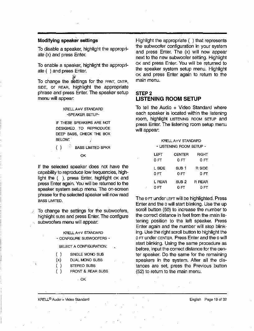
Modifying speaker settings
To disable a speaker, highlight the appropri-ate (×) and press Enter.
To enable a speaker, highlight the appropri-ate ( ) and press Enter.
To change the ~ttings for the FRNT, CNTR,SIDE, or REAR, highlight the appropriatephrase and press Enter. The speaker setupmenu will appear:
KRELL A+V STANDARD-SPEAKER SETUP-
F THESE SPEAKERS ARE NOTDESIGNED TO REPRODUCEDEEP BASS, CHECK THE BOXBELOW:
( BASS LIMITED SPKR
OK
If the selected speaker does not have thecapability to reproduce low frequencies, high-light the (), press Enter, highlight OK andpress Enter again. You will be returned to thespeaker system setup menu. The on-screenphrase for the selected speaker will now readBASS LIMITED.
To change the settings for the subwoofers,highlight SUBS and press Enter. The configuresubwoofers menu will appear:
KRELL A-I-V STANDARD- CONFIGURE SUBWOOFERS -
SELECT A CONFIGURATION:
( SINGLE MONO SUB
(x) DUAL MONO SUBS( STEREO SUBS( FRONT & REAR SUBS
OK
Highlight the appropriate ( ) that representsthe subwoofer configuration in your systemand press Enter. The (x) will now appearnext to the new subwoofer setting. HighlightOK and press Enter. You will be returned tothe speaker system setup menu. HighlightOK and press Enter again to return to themain menu.
STEP 2LISTENING ROOM SETUP
To tell the Audio + Video Standard whereeach speaker is located within the listeningroom, highlight LISTENING ROOM SETUP andpress Enter. The listening room setup menuwill appear:
KRELL A+V STANDARD- LISTENING ROOM SETUP -
LEFT CENTER RIGHTOFT OFT OFT
L SIDE SUB 1 R SIDEOFT OFT OFT
L REAR SUB 2 R REAROFT OFT OFT
The 0 Fm under LEFT will be highlighted. PressEnter and the 0 will start blinking. Use the upscroll button (50) to increase the number the correct distance in feet from the main lis-tening position to the left speaker. PressEnter again and the number will stop blink-ing. Use the right scroll button to highlight the0 FT under CENTER. Press Enter and the o willstart blinking. Using the same procedure asbefore, input the correct distance for the cen-ter speaker. Do the same for the remainingspeakers in the system. After all the dis-tances are set, press the Previous button(52) to return to the main menu.
KRELL® Audio: + Video Standard English Page 19 of 32
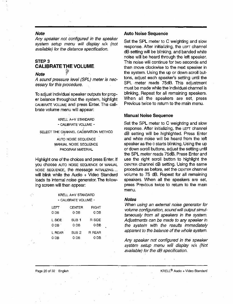
NoteAny speaker not Configured in the speakersystem setup menu will display N/A (notavailable) for the distance specification.
STEP 3CALIBRATE THE VOLUME
Note ~ .~ ~A sound pressure/eve/(SPL) meter is nec-essary for this procedure ....
To adjust individual speaker outputs for prop-er balance throughout the system, highlightCALIBRATE VOLUME and press Enter. The cali-brate volume menu will appear:
KNELL A+V STANDARD
- CALIBRATE VOLUME -
SELECT THE CHANNEL CAI~IBRATION METHOD
AUTO NOISE SEQUENCE
MANUAL NOISE SEQUENCEPROGRAM MATERIAL
Highlight one of the choices and press Enter. Ifyou choose AUTO NOISE SEQUENCE or MANUALNOISE SEQUENCE, the message INITIALIZING...will blink while the Audio + Video Standardloads its internal noise generator. The follow-ing screen will then appear:
KNELL A+V STANDARD
- CALIBRATE VOLUME -
LEFT CENTER RIGHT
0 DB 0 DB 0 DB
L SIDE SUB 1 R SIDE
0 DB 0 DB 0 DB
L REAR SUB 2 R REAR
0 DB 0 DB 0 DB
Auto Noise Sequence
Set the SPL meter to C weighting and slowresponse. After initializing, the LEFT channeldB setting will be blinking, and banded whitenoise will be heard through the left speaker.This noise will continue for two seconds andthen move clockwise to the next speaker inthe system. Using the up or down scroll but-tons, adjust each speaker’s setting until theSPL .meter reads 75dR. This adjustmentmust be made while the individual channel isblinking. Repeat for all remaining speakers.When all the speakers are set, pressPrevious twice to return to the main menu.
Manual Noise Sequence
Set the SPL meter to C weighting and slowresponse. After initializing, the LEFT channeldB setting will be highlighted. Press Enterand white noise will be heard from the leftspeaker as the o starts blinking. Using the upor down scroll buttons, adjust the setting untilthe SPL meter reads 75dR. Press Enter anduse the right scroll button to highlight theCENTER channel dB setting. Using the sameprocedure as before, set the CENTER channelvolume to 75 dB. Repeat for all remainingspeakers. When all the speakers are set,press Previous twice to return to the mainmenu.
NotesWhen using an external noise generator forvolume configuration, sound will output simul-taneously from all speakers in the system.Adjustments can be made to any speaker inthe systehn with the results immediatelyapparent to the balance of the whole system.
Any speaker not configured in the speakersystem setup menu will display N/’A (Notavailable) for the dB specification.
Page 20 of 32 -English KNELL® Audio + Video Standard

The subwoofer designation will changedepending on the configuration entered inthe speaker system setup menu. For a monosetup, the subwoofers are designated SUB 1and SUB 2. For a left and right stereo setup,the subwoofers are designated sue L andsue R. For a fro~ and rear setup, the sub-woofers are designated SUB F and SUB R.
STEP 4CONFIGURE THE INPUTS
To configure inputs, highlight CONFIGURE INPUTSand press Enter. The configure inputs menuwill appear:
KRELL A+V STANDARD- CONFIGURE INPUTS -
E~ T INPUT NAMESSET ANALOG INPUT LEVEL
SET VIDEO INPUT LINKSPAL VIDEO SETUP
Highlight EDIT INPUT NAMES and press Enter.The input name type menu will appear:
KRELL A+V STANDARD- INPUT NAME -
WHAT TYPE OF INPUT NAMEDO YOU WANT TO CHANGE?
VIDEOANALOGDIGITAL
Highlight VIDEO and press Enter. The inputname menu will appear:
KRELL A+V STANDARD- INPUT NAME -
WHICH INPUT NAMEDO YOU WANT TO CHANGE?
S-VIDEO INPUTSSVl SV2 SV3 SV4
COMPOSITE VIDEO INPUTSCVl CV2 CV3 CV4
Highlight any of the S-video or compositevideo inputs and press Enter. A secondaryscreen will appear (S-video 1 is shown as anexample):
KRELL A+V STANDARD- INPUT NAME -
INPUT: S-VIDEO 1NAME: S-VIDEO 1
e-- & --> TO MOVE CURSOR1" & $ TO CHANGE TEXT
PRESS ENTER WHEN DONE
The first letter of the input name will blink andcan be changed using the up or down scrollbuttons. Move the blinking cursor to the letteryou want to change and adjust to the letter ofyour choice. The name field is limited to amaximum of 12 characters. Available char-acters are:
A-Z 1-9 ’ < >
and a blank space. When completed, pressEnter to finish the editing and return to theinput name menu. Choose another input toadjust or press Previous to return to the inputname menu, Choose another input name tomodify or press Previous to return to theconfigure inputs menu.
KRELL® Audio + Video Standard English Page 21 of 32

Special Analog Sources
The analog input sensitivity of the Audio +Video Standard is set for the standard 2 Voltsthat Dolby Laboratories mandates for properDolby Pro Logic processing. For analogsources (components connected to $1-$5and tape) that do n~correspon.d to a stan-dard 2 Volt output ~pecificationl, it may benecessary to adjust individual input levels onthe Audio + Video Standard.
Press Menu to exit the menu system, selectthe desired analog input and return to theconfigure inputs menu.
Highlight SET ANALOG INPUT LEVEL and pressEnter. The set input .levels menu will appear:
- SET It~PUT LEVELS -
INPUT: B1
L R
- OVERLOAD -
LEVEL: 0 DB
OK
Begin playback of the selected source usingprogram material with loud passages. PressEnter. The LEVEL dB specification will beginblinking.
If the source unit’s output is greater than thestandard 2 Volts, OVERLOAD will blink indicat-ing an input signal greater than standard.Using the down scroll button, lower the leveldb setting until OVERLOAD stops blinking. "
Conversely, if the source unit’s output .is lessthan the standard 2 Volts, it will be necessaryto raise the input level sensitivity for properDoiby surround processing. Using the up
scroll button, raise the level dB setting untilOVERLOAD starts blinking and then reduce thesetting just below this threshold.
When the input level has been properly set,highlight OK and press Enter to return to theconfigure inputs menu. To adjust additionalinputs, exit the menu system by pressingMenu, select the desired input, return to theset input levels menu within the configureinputs menu, and follow the same procedureas above.
Linking a Video Inputto an Audio Input
Each video input (S-video and compositevideo) may be linked to a specific audio inputand surround mode. Therefore, when avideo input is configured and then selected,its matching audio input and surround modewill also engage. Highlight sET VIDEO INPUTLINKS within the configure inputs menu andpress Enter. The set video input links menuwill appear:
KRELL A+V STANDARD- SET VIDEO INPUT LINKS -
WHICH VIDEO INPUT LINKS
WOULD YOU LIKE TO SET?
S-VIDEO INPUTS
SVl SV2 SV3 SV4
COMPOSITE VIDEO INPUTSCV1 CV2 CV3 CV4
Highlight any of the S-video or compositevideo inputs and press Enter. A secondaryscreen will appear:
Page 22 of 32 - English KNELL® Audio + Video Standard

KRELL A+V STANDARD- LINK INPUT -
WHICH INPUT LINK
DO YOU WANT TO CHANGE?
ANALOG
%~,DIGITAL~ MODE
Highlight the audio input style, either ANALOGor DIGITAL, and press Enterl If ANALOG isselected, an additional screen appears:
KRELL A+V STANDARD- LINK INPUT -
SELECT AN ANALOG INPUTTO ~INK TO SVI:
( )B1 ( )Sl ( ( )s4
OK
Highlight the appropriate analog input andpress Enter. When completed, highlight OKand press Enter to return to the link inputmenu. At this point you may choose a digitalinput or operating mode to link with theselected video input.
To select a linked digital input, highlight DIGITALand press Enter. The digital link input screenwill appear:
KRELL A+V STANDARD
- LINK INPUT -
SELECT A DIGITAL INPUTTO LINK TO SV1 :
( ).COAX ( ) OPTIC
( ) COAX ( ) OPTIC
( ) AES-EBU ( )
OK
NoteIf a video input is linked to both a digital andan analog input, the Audio + Video Standardwill select the digital input as the main audiosource whenever the video input is selected.
When completed, highlight OK and pressEnter to return to the link input menu. At thispoint you may choose to change the linkedoperating mode. To change a linked operat-ing mode, highlight MODE and press Enter.The operating mode link input screen willappear:
KRELL A+V STANDARD
- LINK INPUT o
SELECTA MODE TO LINKTO SVl :
(X) MOVIE( ) MUSIC( ) PREAMP
OK
NotesIf a video input is linked to a digital input andMOVIE is in the linked mode, the Audio + VideoStandard will select the appropriate digitalsurround processing mode, either Dolby ProLogic, Dolby Digital or DTS, depending uponwhich signal is present.
If a video input is linked to an analog inputand MOVIE is the linked mode, the Audio +Video Standard will select Dolby Pro Logicas the surround processing mode.
If a video ir~put is linked to any analog or digi-tal input and MUSIC or PREAMP is the linkedmode, the Audio + Video Standard willproce, ss the linked audio signal in the select-ed mode, unless the input is a digital signalcontaining either Dolby Digital or DTS data. In
KRELL® Audio -+ Video Standard English Page 23 of 32

this case, the appropriate processing modewill be selected.
Highlight the desired mode and press Enter.When completed, highlight OK and pressEnter to return to the link input menu. Selectanother video input to I!#~k or press Previousto return to the configu~ inputs menu.
Direct Access Remote ControlSystem Programming
System programming functions allow you tosimplify the use of your Audio + VideoStandard by naming three sets of linkedinputs, System 1, 2, and 3 (47). Other linksmay be created in the Audio + VideoStandard, but primary, links may be set upand remembered more easily with theSystem function. For example:
System button 1 A laser disc con-nected to the RF input and a videoinput, set for MOVIE MODE.
System button 2 A DVD player con-nected to the C1 input and a videoinput, set for MOVIE MODE,
System button 3 A CD player con-nected to an analog input and anunused video input, set for preampmode.
To use the system programming function,the basic input links need to be created.For details, see Linking a Video Input toan Audio Input on page 22. To assigninput links to System 1, 2, or 3, follow theinstructions below.
Push and release one of the three sys-teaq buttons.
Decide which video input you want toassign to the system button. Push and
hold the appropriate video button downfor approximately five seconds. Note thatthe red LED in the upper left corner of theremote control will blink. When the blink-ing stops and the light stays lit for onesecond the system is linked to the videoinput you selected.
Link the video inputs to a specific audioinput and surround mode.
Selecting the Broadcast Standard
The Audio + Video Standard will operate inboth the NTSC and PAL broadcasting stan-dards. For countries that only use the NTSCbroadcasting standard, all S-video and com-posite video inputs are already set for prop-er NTSC operation. For countries that useboth the NTSC and PAL broadcasting sys-tems, the SV-3, SV-4, CV-3, and CV-4 arefactory set to the PAL operating system. Toadjust the broadcast operating settings forany of the video inputs, enter the PAL videosetup menu located within the configureinputs menu:
KRELL A+V STANDARD- PAL VIDEO SETUP -
SELECT THE INPUTS THAT
HAVE PAL VIDEO SOURCES:
( )sv-1 ()cv-1( ) sv-2( ) cv-2( ) sv-3( ) cv-3( ) sv-4( ) cv-4
OK
Highlight the inputs that have PAL videosources attached to them and press Enterso that an,(x) appears next to the desiredinput. To defeat a PAL video source, pressEnter so the x disappears. When completed,highlight OK and press Enter to return to the
Page 24 of 32 English KRELL® Audio + Video Standard

configure inputs menu. Press Previous toreturn to the main menu.
STEP 5CONFIGURE THE MUSIC MODE
It is often desiral~e to have the settings formusic listening dl~erent from movie listening.Highlight CONFIGURE MUSIC MODE and press
Enter. The configure music mode screen willappear:
KRELL A+V STANDARD
- CONFIGURE MUSIC MODE -
THE A+V STANDARD WILL
BE SET TO MUSIC MODE.
OK TO CONTINUE?
YES NO
Highlight YES and press Enter. The configuremusic mode screen will appear:
KRELL A-I-V STANDARD- CALIBRATE MUSIC MODE -
ADJUST OUTPUT LEVELS
CONFIGURE SPEAKERS
- NOTE -
THESE ADJUSTMENTS AREFOR MUSIC MODE ONLY!
Highlight CONFIGURE SPEAKERS and pressEnter. A second screen will appear:
KRELL A+V STANDARD
- CONFIGURE MUSIC MODE -
SELECT THE SPEAKERS TO
BE ACTIVE IN MUSIC MODE.
( ) SIDE SPEAKERS
( ) REAR SPEAKERSOK
Highlight the speakers to be active in themusic mode and press Enter. When com-pleted, highlight OK and press Enter to returnto the main configure music mode menu.Before proceeding, highlight ADJUST OUTPUTLEVELS and press Enter. The configure musicmode menu will appear:
KRELL A+V STANDARD- CALIBRATE MUSIC MODE -
LEFT RIGHT
0 DB 0 DB
L SIDE SUB 1 R SIDE
0 DB 0 DB 0 DB
L REAR SUB 2 R REAR0 DB 0 DB 0 DB
The displayed speaker array will duplicatethe system profile input into the speaker sys-tem setup menu. The center speaker is notdisplayed because it is not active in themusic mode. The Audio + Video Standard isnow calibrated and setup for all moviemodes and music mode, Select the appro-priate audio and video input and simply turnup the volume.
KRELL® Audio + Video Standard English Page 25 of 32

OperationThe operation menu offers options for a vari-ety of Audio + Video Standard user opera-tions and features. From the main menu, high-light OPERATION and press Enter. This opera-tion menu will appe~:
KRELL A-IV STANDARD- OPERATION -
BACKGROUND COLORMAIN VOLUME DISPLAY
ON-SCREEN DELAY TIME
INPUT LINK PROPERTIESREMOTE CONTROL SENSOR
FULL SURROUND SETUPANTI-CLIP CONTROL
BACKGROUNI~~ COLOR
Highlight BACKGROUND COLOR and pressEnter. The background color menu willappear:
KRELL A+V STANDARD
- BACKGROUND COLOR -
MENU BACKGROUND COLOR:(X) BLACK( ) BLUE
( ) GREEN
( ) RED
OK
The default background color is black. If blue,green, or red is preferred, highlight theappropriate ( ) and press Enter. The back-ground color will immediately change to the.new setting. When you are finished, highlight(~K and press Enter to return to the operationmenu.
VOLUME
The default on-screen volume display isnumerical. The Audio + Video Standard’s vol-ume control ranges from 0 to 152 with 89representing the Dolby reference level. Tochange the main volume to a bar graph dis-play, highlight MAIN VOLUME DISPLAY and pressEnter. The main volume display menu willappear:
KRELL A+V STANDARD- MAIN VOLUME DISPLAY -
HOW WOULD YOU LIKE THEMAIN VOLUME DISPLAYED?
(X) BARGRAPH DISPLAY
( ) NUMERIC DISPLAY
OK
Highlight the ( ) beside BARGRAPH DISPLAYand press Enter. The on screen display willnow show the current volume setting relativeto maximum volume. Total volume is repre-sented by sixteen dots. As volume increas-es, squares replace the dots. At Dolby refer-ence level 89, the volume control pausesand displays REF on screen. When finished,highlight OK and press Enter to return to theoperation menu.
ON-SCREEN DELAY TIME
On-screen information remains visible forthree seconds. The on-screen delay timehas a range from one to five seconds. Toadjust, highl!ght ON-SCREEN DELAY TIME andpress Enter. The on-screen delay time menuwill appear:
Page 26 of 32 -English KRELL® Audio + Video Standard

KRELL A+V STANDARD- ON-SCREEN DELAY -
HOW LONG WOULD YOU LIKETHE TEXT TO REMAIN ON
THE SCREEN AFTER VOLUMEADJUSTMENT OR CHANGING
INPUT~AND MODES?
3 SECONDS
Press Enter and the 3 will begin blinking. Usethe up or down scroll buttons to increase ordecrease the on-screen time setting andthen press Enter to lock in the new setting.When finished, press Previous to return tothe operation menu.
INPUT LINK PROPERT, IESy
The input linking feature activates as soonas the inputs are joined in the configureinputs menu. These links are not shown on-screen unless instructed. To change either ofthese settings, highlight INPUT LINK PROPER-TIES and press Enter. The input link proper-ties menu will appear:
KRELL A+V STANDARD- INPUT LINK PROPERTIES -
(X) ENABLE INPUT LINKS
( ) SHOW LINKS WHILECHANGING INPUTS
OK
To disable the input links, highlight the (x)next to ENABLE INPUT LINKS and press Enter.The video, audio, and mode settings nowoperate independently. To display the inputlinks, highlight the ( ) next to SHOW LINKS"WHILE CHANGING INPUTS and press Enter. Thevideo, audio, and mode settings of the activelink plus the current volume setting will be
displayed on-screen whenever a video inputis changed.
REMOTE CONTROL SENSOR
The Audio + Video Standard receives infraredremote commands at the front panel infraredsensor (18). Additionally, the Audio + VideoStandard features a duplicate remote sensorand a male baselJand infrared connector (29)on the rear panel. These rear panel infraredcomponents may be used to facilitate a cus-tom installation. To activate these features,highlight REMOTE CONTROL SENSOR and pressEnter. The remote control sensor menu willappear:
KRELL A+V STANDARD- REMOTE CONTROL SENSOR -
(X) USE FRONT SENSOR
( ) USE REAR SENSOR
OK
Highlight the ( ) next to USE REAR SENSOR andpress Enter. The rear infrared sensor willnow be active and the front ~panel infraredsensor will be disabled. When finished, high-light OK and press Enter to return to the oper-ation menu.
NoteTo reactivate the front infrared sensor, theAudio + Video Standard must be in standbymode. While holding the front panel S-videobutton (6) and the composite video button (5)down, simultaneously press the power but-ton (8).
FULL SURROUND SETUP
For systems with both side and rear speak-ers, the Audio + Video Standard offers theoption of operating both pairs of surround
KRELL® Audio ÷ Video Standard English Page 27 of 32

speakers in all theater modes. To activateboth pairs of speakers in any theater mode,highlight FULL SURROUND SETUP OI3 the opera-tion menu and press Enter. The full surroundsetup menu will appear:
KNELL~.{~V STANDARD- FULL S~OUND SETUp -
IF YOU WOULD LIKE BOTHTHE SIDES AND REARS ACTIVE
IN ALL THEATER MODES
CHECK THE BOX BELOW:( ) FULL SURROUND MODE
OK
Highlight the ( ) next to FULL SURROUND MODEand press Enter. When finished, highlight OKand press Enter to return to the operationmenu.
ANTI CLIP CONTROL
For proper Dolby Pro Logic surround pro-cessing when using an analog source, alqanti-clip circuit is used to prevent over-drivingthe Dolby surround processing circuitry. The
Audio + Video Standard presents a CD orDAT recordable signal to the digital outputswhen an analog signal is inputted. Whenrecording an analog music source onto adigital medium, the use of the anti-clip con-trol may limit dynamics and impart anunwanted compression to the music.
To disable the anti-clip control, highlight ANTI-CLIP CONTROL OI3 the operation menu andpress Enter. The anti-clip control menu willappear:
KNELL A+V STANDARD- ANTI-CLIP CONTROL -
(X) ENABLE
( ) DISABLE
OK
Highlight the ( ) next to DISABLE and pressEnter. When finished, highlight OK and pressEnter to return to the operation menu.
NoteThe anti-clip control will be reactivated whenan input is changed.
Page 28 of 32 -English KNELL® Audio + Video Standard

Saving, Recalling, andClearing Configurationsettings
To save your configuration settings, turn theAudio + Video Standard off from the frontpanel or the rem~e control. While pressingthe recall button (’~7), press the power button(8) on the front panel. The main display willread SAVE CNFG when the settings have beenstored in the Audio + Video Standard’s non-volatile memory.
To recall your stored configuration settings,press Recall until RSTR CNFG appears in themain display. This will take thirteen seconds.
To clear all settings, turn the Audio + VideoStandard off from the front panel or the remotecontrol. While pressing both master (19) andbalance (21) buttons, press the power buttonon the front panel. The main display will readCLR when the settings have been erased fromthe Audio + Video. Standard’s non-volatilememory.
KRELL® Audio ÷ Video Standard English Page 29 of 32

Warranty
KrelP warrants this product to be free fromdefects in material or workmanship for aperiod of five years for circuitry from the orig-inal date of purchase. Should this product failto perform at any time during the warranty,Krell® will repair~ at no cost to the owner,except as set fo~h in this warranty. Transferof warranty to a second owner occurs auto-matically. Please contact Krell® to have thename on the warranty changed. Transfer ofwarranty does not extend the duration of theoriginal warranty period.
NoteThis warranty does not apply to damagecaused by acts of God or nature.
The warranty period begins on the date ofretail purchase~as noted on the retail salesslip provided by an authorized Krell® dealeror distributor, or on the warranty registrationcard sent to Krell®. In the event that an ade-quate proof of purchase date is unavailable,the warranty period will begin on the date theproduct was originally shipped from the fac-tory. The warranty described in this para-graph shall be in lieu of any other warranty,express or implied, including, but not limitedto, any implied warranty of merchantability orfitness for a particular purpose. There are nowarranties which exceed beyond thosedescribed in this document. If this productdoes not perform as warranted herein, theowner’s sole remedy shall be repair. In noevent will Krell® be liable for incidental or con-
sequential damages arising from purchase,use, or inability to use this product, even ifKrelP has been advised of the possibility ofsuch damages.
The warranty for this KrelP product is validonly in the country to which the product wasoriginally shipped, through the authorizedKrell® distributor for that country, and at thefactory. There may be restrictions on orchanges to Krell’s warranty because of reg-ulations within a specific country. Pleasecheck with your distributor for a completeunderstanding of the warranty in your coun-try.
Freight to the factory is your responsibility.Return freight within the United States(U.S.A.) is included in the warranty, if youhave purchased your Krell ® product outsidethe U.S.A. and wish to have it serviced at thefactory, all freight and associated charges tothe factory are your responsibility. Krell® willpay return freight to the U.S.A.-based freightforwarder of your choice. Freight and othercharges to ship the product from the freightforwarder to you are also your responsibility.
The operating voltage of this product isdetermined at the factory and can only bechanged by an authorized Krell® distributoror at the factory. The voltage for this productin the U.S.A. cannot be changed for sixmonths from the original purchase date.
Any unauthorized voltage conversion,disassembly, component replacement,perforation of chassis, Updates, ormodifications performed to the productwill void the warranty.
Page 30 of 32 - English KRELL® Audio + Video Standard

Return AuthorizationProcedureIMPORTANTff you believe there is a problem with yourcomponent, please contact your dealer, dis-tributor, or the ~IP factory to discuss theproblem before you return the component forrepair. To expedite service, you may wish tocomplete and e-mail the Service RequestForm on our website at wwvckrel/online.com.
To return a product to KrelP, please fol-low this procedure so that we may serveyou better:
1. Obtain a Return Authorization Number(R/A number)and shipping address fromthe Krell® Service Department.
2. Insure and accept all liability for loss ordamage to the product during shipmentto the Krell® factory and prepay all ship-ping charges. The product may also behand delivered if arrangements with theService Department have been made inadvance. Proof of purchase may berequired for warranty validation at thetime of hand delivery.
3. Use the original packaging to insure thesafe transit of the product to the factory,dealer, or distributor. The use of anypackaging material other than the origi-nal packaging materials is not recom-mended. Krell ® may, at its discretion,return a product in new packaging andbill the owner for such packaging if theproduct received by Krell® was boxed innon-standard packaging or if the originalpackaging was so damaged thatit wasunusable. If Krell ® determines that newpackaging is required, the owner will benotified before the product is returned. Topurchase-additional packaging, please
contact your authorized Krell® dealer, dis-tributor, or the Krell® Service Departmentfor assistance.
Krell ® is not responsible for any damageincurred in transit. Krell® will file claims fordamages as necessary for products dam-aged in transit to the factory. The owner isresponsible for filing claims for shippingdamages that occur during the return ship-ment.
Replacement parts and/or products will befurnished on an exchange basis only; anyparts and/or products returned to Krell® forexchange become the property of Krell®
No expressed or implied warranty is madefor any Krell® product damaged by accident,abuse, misuse, natural or personal disaster,or unauthorized modification.
In the event Krell® receives a product for war-ranty service which has been modified in anyway without Krell ® authorization, all war-ranties on that product will be void, The prod-uct will be returned to original factory layoutspecifications at the owner’s expense beforeit is repaired. All repairs required after theproduct has been returned to original factoryspecification will be charged to the customer,at current parts and labor rates.
To contact the Krell® Service De ~artment
TEL 203-799-9954Monday-Friday9:00 AM to 5:00 PM EST
FAX 203-799-9796
E-MAIL krell @ krellonline.com
Audio + Video StandardPRODUCT SERIAL NUMBER
~’~ register your product for warranty benefits,complete and return the Warranty RegistrationCard enclosed in the shipping box within 15days of purchase.
KRELL® Audio-q- Video Standare English Page 31 of 32

Krell® Industries, Inc.45 Cohnair RoadOrange, CT 06477-3650 USA
TEL 203-799-9954 FAX 203-799-9796E-MAIL krell @ krellon!i~.comWEB SITE www.krell~line.com
Audio + Video StandardSurround
Preamp/Processor
SpecificationsANALOG AUDIO INPUTS
5 single-ended via RCA1 balanced via XLR1 single-ended tape input
DIGITAL AUDIO ~NPUTS
2 coaxial, 2 TosLink’M1 AES/EBU1 RF input for Dolby Digital (AC-3)
VIDEO INPUTS
4 S-Video4 Composite1 BNC
ANALOG CHANNEL OUTPUT
heft, center, right, side surrounds, rear sur-rounds, 2 subwoofers
Balanced via XLR,or single-ended via RCA
ANALOG TAPE OUTPUTS "
1 audio via RCA2 video via RCA
DIGITAL OUTPUTS
1 coaxial1 TosLink"
VIDEO OUTPUTS
3 S-Video(1 with on-screen graphics)
3 Composite(1 with on-screen graphics)
1 BNC(with on-screen graphics)
LISTENING MODES
Dolby Digital (AC-3), DTS, Dolby ProLogic, Music, Mono, Preamp
DIMENSIONS
19w x 6.75h x 17d in.48.3w x 17.2h x 43.2d cm.
WEIGHT
Shipped 42 Ibs., 19.1 kgUnit only " 24 Ibs., 10.9 kg
All operational features, functions, specifications, andpolicies are subject to change without notification.