AUDIO COMPRESSION - OpenCores
21
AUDIO COMPRESSION Table of Contents TABLE OF CONTENTS ............................................................................................2 OVERVIEW ............................................................................................................3 1.1 PROJECT GOALS.........................................................................................3 1.2 DESIGN REQUIREMENTS........................................................................... 3 1.3 THEORY.................................................................................................... 3 1.4 SYSTEM OVERVIEW................................................................................... 6 1.5 BLOCKS OVERVIEW.................................................................................... 8 2.1 Vhdl codes 9 3.1 Simulation 17 3.2 Synthesis report 19 4.1 Further Improvements 22 5.1 Team member contributions 22 6.1 References 22
Transcript of AUDIO COMPRESSION - OpenCores

AUDIO
COMPRESSION
Table of Contents
TABLE OF CONTENTS ............................................................................................2
OVERVIEW............................................................................................................3
1.1 PROJECT GOALS.........................................................................................3
1.2 DESIGN REQUIREMENTS........................................................................... 3
1.3 THEORY.................................................................................................... 3
1.4 SYSTEM OVERVIEW................................................................................... 6
1.5 BLOCKS OVERVIEW.................................................................................... 8
2.1 Vhdl codes 9 3.1 Simulation 17 3.2 Synthesis report 19 4.1 Further Improvements 22 5.1 Team member contributions 22 6.1 References 22
Page 2
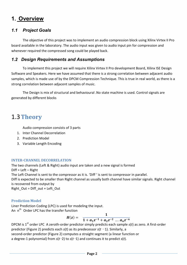
1. Overview 1.1 Project Goals
The objective of this project was to implement an audio compression block using Xilinx Virtex II Pro
board available in the laboratory. The audio input was given to audio input pin for compression and
whenever required the compressed song could be played back.
1.2 Design Requirements and Assumptions
To implement this project we will require Xilinx Virtex II Pro development Board, Xilinx ISE Design
Software and Speakers. Here we have assumed that there is a strong correlation between adjacent audio
samples, which is made use of by the DPCM Compression Technique. This is true in real world, as there is a
strong correlation between adjacent samples of music.
The Design is mix of structural and behavioural .No state machine is used. Control signals are
generated by different blocks
1.3 Theory
Audio compression consists of 3 parts
1. Inter Channel Decorrelation
2. Prediction Model
3. Variable Length Encoding
INTER-CHANNEL DECORRELATION
The two channels (Left & Right) audio input are taken and a new signal is formed
Diff = Left – Right
The Left Channel is sent to the compressor as it is. ‘Diff ‘ is sent to compressor in parallel.
Diff is expected to be smaller than Right channel as usually both channel have similar signals. Right channel
is recovered from output by
Right_Out = Diff_out + Left_Out
Prediction Model
Liner Prediction Coding (LPC) is used for modeling the input.
An nth
Order LPC has the transfer function
���� = �
� + ��� + ��� … . ���
DPCM is 1st
order LPC A zeroth-order predictor simply predicts each sample s(t) as zero. A first-order
predictor (Figure 2) predicts each s(t) as its predecessor s(t − 1). Similarly, a
second-order predictor (Figure 2) computes a straight segment (a linear function or
a degree-1 polynomial) from s(t−2) to s(t−1) and continues it to predict s(t).

Page 3
Figure 2
“For maximum compression, it is possible to compute all four predictors and their
errors and select the smallest error. However, experience gained by the developer of the
method indicates that even a zeroth-order predictor results in typical compression of
48%, and going all the way to third-order prediction improves this only to 58%. For most
cases, there is therefore no need to use higher-order predictors, and the precise predictor
used should be determined by compression quality versus run time considerations.
Shorten Codec uses linear (second-order) prediction.” [1]
Figure Distribution of Audio Samples , and Differences.
DPCM
DPCM or differential pulse-code modulation is a signal encoder that uses the baseline of PCM but adds
some functionalities based on the prediction of the samples of the signal.
DPCM was invented by C. Chapin Cutler at Bell Labs in 1950.[2]
Differences between Consecutive values are sent. Initially a starting value is sent then the differences.
The difference values eq[n] are coded with variable width. Huffman coding can be used for better
compression at the cost of more complexity. Smaller values are given shorter code length, thus high
compression is achieved if adjacent values are do not change much.

Page 4
Variable Length Encoding:
We assume smaller values are more frequent than larger values.
Depending on the input value the input value is coded as 5,10,15,20 bit value.
The difference values are sent as 5 bit data stream. They are sent 1,2,3,4 times depending on the size of
input.
This is not instantaneous code.
New code indicator ‘1’ implies start of new code.’0’ indicates continuation of old code.
Values less than 2^4 require one block = 5 bits. 3 bits for magnitude one for sign.
Values less than 2 ^(4+4) would require two blocks = 10 bits.
Values less than 2^(4+4+4) would require 15 bits.
Worst case a 16 bit code would require 20 bits.
Best Case 5 bit out of 16.
Each input value is compared with 2^4, 2^8, 2^12 then the input values are shifted appropriate amount,
required no of blocks are sent out as bit stream.
Decoding starts by taking in 5 bits at a time. If the first value is ‘1’ previous value is expanded into 16 bit
and sent out. Else the received value is concatenated to the previous value.

Page 5
1.4 System Overview
The block diagram of the project can be shown as follows
Virtex II Pro Development System
Virtex II Pro FPGA
Decoder Block
AC97
Audio AC97 Audio
Encoder Block Controller Codec Chip
The AC97 is used to capture audio data, where each sample is converted into 16 bit data. This 16 bit
data which is obtained from the AC97 controller is then sent to the Compressor system comprising of
Encoder block and Decoder block. The Encoder block encodes the received 16-bit data using DPCM coding
technique. This encoded data is sent to the Decoder block which does the opposite and reconstructs the
original data, which is given back to the AC97 Controller which converts it into analogue form and is output
through the speakers.
The codes for instantiating AC97 for audio input and output was taken from the readymade codes
available in the CD provided with the Virtex II PRO Board.

Page 6
1.5 Block Overview
Here we look at the block by block details of our project. The project can be divided into different
modules as shown below.
16 trd 16
a Encoder Block 5 Decoder Block so
ds
clk48 clk390 clk48 Compressor
The top module is compressor, which has two blocks- encoder and decoder. It accepts 16 bit
data sent in by the AC97 controller block. It requires two different clocks for its working; they are
48 kHz and 390 kHz. This is generated from the system clock which runs at 100 MHz. A clock divider
is used to do the same. Inter connections between the encoder and decoder module is done here.
The internal structure of encoder module is shown below.
Present value
a a + 15 3 0
ALU temp
b -
Previous value
3 0
encvalue
ds(new bit indicator) trd (encoded value)

Page 7
The 16-bit data coming in from the AC97 controller is stored in a register ‘a’, and a separate register
‘b’ is used for storing previous value. The ALU subtracts the previous value from the present value. The
result is stored in a temporary register ‘temp’. Now the 16th
bit is stored in the first position. This is done to
remember whether the difference was a positive or negative number. The top 12 bits are now negated (1’s
complement is done) if the LSB( the actual MSB) is ‘1’. Else, its passed as it is. The lower four bits of the
temporary register is stored in the ‘encvalue’ register. The lower four bits of the encvalue register are now
the encoded value of the audio sample. An audio sample can take any number of 4 bit encvalue values. The
enc value register is shifted right 4 bits at a time and sent for decoding. The four bits generated are
concatenated with a new value indiacator which is generated in the encoder block.
The internal structure of the decoder block is as shown below.
k
ADDER Decoded value
trd
Control
Ds( New value indicator)
The encoded value is put in different places in the register ‘k’ by the control to align it
properly. This reconstructs encvalue register of the encoder. Now it is added to the previous decoded
value by the adder block. The previous decoded value is stored in a separate register. The final output is
got from the decoded value register. This is sent to the AC97 controller which then is output by the
speaker. This completes encoding and decoding.
Page 8
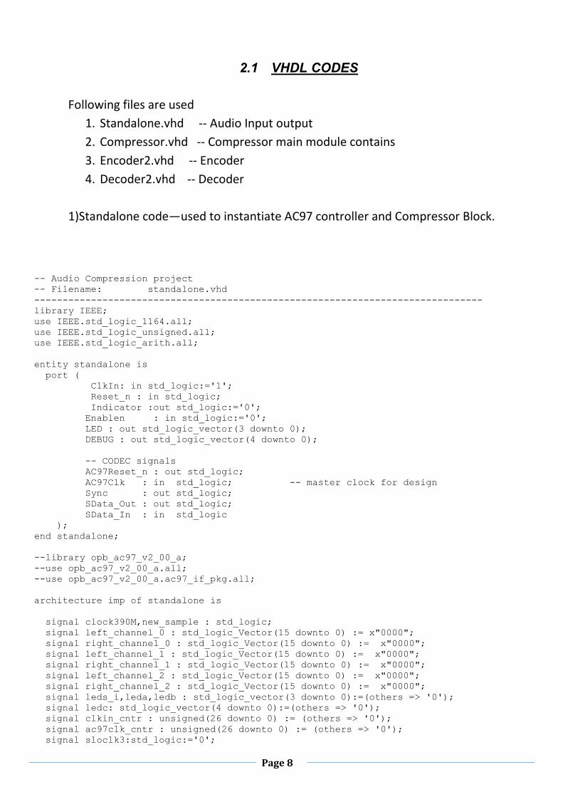
2.1 VHDL CODES
Following files are used
1. Standalone.vhd -- Audio Input output
2. Compressor.vhd -- Compressor main module contains
3. Encoder2.vhd -- Encoder
4. Decoder2.vhd -- Decoder
1)Standalone code—used to instantiate AC97 controller and Compressor Block.
-- Audio Compression project -- Filename: standalone.vhd ------------------------------------------------------------------------------- library IEEE; use IEEE.std_logic_1164.all; use IEEE.std_logic_unsigned.all; use IEEE.std_logic_arith.all; entity standalone is port ( ClkIn: in std_logic:='1'; Reset_n : in std_logic; Indicator :out std_logic:='0'; Enablen : in std_logic:='0'; LED : out std_logic_vector(3 downto 0); DEBUG : out std_logic_vector(4 downto 0); -- CODEC signals AC97Reset_n : out std_logic; AC97Clk : in std_logic; -- master clock for design Sync : out std_logic; SData_Out : out std_logic; SData_In : in std_logic ); end standalone; --library opb_ac97_v2_00_a; --use opb_ac97_v2_00_a.all; --use opb_ac97_v2_00_a.ac97_if_pkg.all; architecture imp of standalone is signal clock390M,new_sample : std_logic; signal left_channel_0 : std_logic_Vector(15 downto 0) := x"0000"; signal right_channel_0 : std_logic_Vector(15 downto 0) := x"0000"; signal left_channel_1 : std_logic_Vector(15 downto 0) := x"0000"; signal right_channel_1 : std_logic_Vector(15 downto 0) := x"0000"; signal left_channel_2 : std_logic_Vector(15 downto 0) := x"0000"; signal right_channel_2 : std_logic_Vector(15 downto 0) := x"0000"; signal leds_i,leda,ledb : std_logic_vector(3 downto 0):=(others => '0'); signal ledc: std_logic_vector(4 downto 0):=(others => '0'); signal clkin_cntr : unsigned(26 downto 0) := (others => '0'); signal ac97clk_cntr : unsigned(26 downto 0) := (others => '0'); signal sloclk3:std_logic:='0';

Page 9
signal debug_i : std_logic_vector(3 downto 0); signal reset_i : std_logic; signal ac97reset_n_i,sync_i,sdata_out_i : std_logic; signal do: std_logic_Vector(15 downto 0) := x"0000"; signal Diff: std_logic_Vector(15 downto 0) :=(others => '0'); signal en: std_logic:='1'; component Compressor2 is Port ( a : in STD_LOGIC_VECTOR (15 downto 0); so : out STD_LOGIC_VECTOR (15 downto 0); sysclkin : in STD_LOGIC; led :out std_logic_vector(3 downto 0); en : in STD_LOGIC:='1'); end Component; component ac97_if is port ( ClkIn : in std_logic; Reset : in std_logic; -- All signals synchronous to ClkIn PCM_Playback_Left: in std_logic_vector(15 downto 0); PCM_Playback_Right: in std_logic_vector(15 downto 0); PCM_Playback_Accept: out std_logic; PCM_Record_Left: out std_logic_vector(15 downto 0); PCM_Record_Right: out std_logic_vector(15 downto 0); PCM_Record_Valid: out std_logic; Debug : out std_logic_vector(3 downto 0); AC97Reset_n : out std_logic; -- AC97Clk -- CODEC signals (synchronized to AC97Clk) AC97Clk : in std_logic; Sync : out std_logic; SData_Out : out std_logic; SData_In : in std_logic ); end component ac97_if; begin en <= Enablen; reset_i <= not Reset_n; ---------------------------------------------------------------------------------- ---- Inter channel decorrelation. Stereo Lc:compressor2 Port map(left_channel_0,left_channel_2,clkin,leda,en); Dc:compressor2 Port map(Diff,Do,clkin,ledb,en); right_channel_2 <= left_channel_2 + Do; Diff <= left_channel_0 - right_channel_0; --right_channel_2 <= left_channel_0; ------------------------------------------------------------------------------------ ---------------------------------------------------------------------------------- ledc <= ('0' & leda) +('0' & ledb); LED <= ledc(4 downto 1); ---------------------------------------------------------------------------------- ---------------------------------------------------------------------------------- -- Standard code given in documentation ---------------------------------------------------------------------------------- ac97_if_I : ac97_if
Page 10
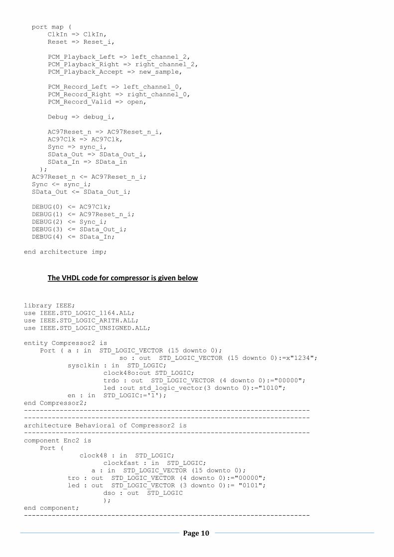
port map ( ClkIn => ClkIn, Reset => Reset_i, PCM_Playback_Left => left_channel_2, PCM_Playback_Right => right_channel_2, PCM_Playback_Accept => new_sample, PCM_Record_Left => left_channel_0, PCM_Record_Right => right_channel_0, PCM_Record_Valid => open, Debug => debug_i, AC97Reset_n => AC97Reset_n_i, AC97Clk => AC97Clk, Sync => sync_i, SData_Out => SData_Out_i, SData_In => SData_in ); AC97Reset_n <= AC97Reset_n_i; Sync <= sync_i; SData_Out <= SData_Out_i; DEBUG(0) <= AC97Clk; DEBUG(1) <= AC97Reset_n_i; DEBUG(2) <= Sync_i; DEBUG(3) <= SData_Out_i; DEBUG(4) <= SData_In; end architecture imp;
The VHDL code for compressor is given below
library IEEE; use IEEE.STD_LOGIC_1164.ALL; use IEEE.STD_LOGIC_ARITH.ALL; use IEEE.STD_LOGIC_UNSIGNED.ALL; entity Compressor2 is Port ( a : in STD_LOGIC_VECTOR (15 downto 0); so : out STD_LOGIC_VECTOR (15 downto 0):=x"1234"; sysclkin : in STD_LOGIC; clock48o:out STD_LOGIC; trdo : out STD_LOGIC_VECTOR (4 downto 0):="00000"; led :out std_logic_vector(3 downto 0):="1010"; en : in STD_LOGIC:='1'); end Compressor2; ------------------------------------------------------------------------ ------------------------------------------------------------------------ architecture Behavioral of Compressor2 is ------------------------------------------------------------------------ component Enc2 is Port ( clock48 : in STD_LOGIC; clockfast : in STD_LOGIC; a : in STD_LOGIC_VECTOR (15 downto 0); tro : out STD_LOGIC_VECTOR (4 downto 0):="00000"; led : out STD_LOGIC_VECTOR (3 downto 0):= "0101"; dso : out STD_LOGIC ); end component; ------------------------------------------------------------------------

Page 11
component Encoder is Port ( clock48,clockfast:in std_logic:='1'; a : in STD_LOGIC_VECTOR (15 downto 0); --input 16 bit value tro:out std_logic_vector (4 downto 0); led:out std_logic_vector (3 downto 0):=(others=>'0'); dso:out std_logic ); end component; ------------------------------------------------------------------------ component Decoder is Port ( clock48:in std_logic:='1'; ds:in std_logic; --- acts as asychronous clock trd:in std_logic_vector (4 downto 0):="00000"; --- input encoded stream sampled at 'ds'; so :out std_logic_vector (15 downto 0) --- decoded value output ); end component; ------------------------------------------------------------------------ component Encoder2 is Port ( clock48,clockfast:in std_logic:='1'; a : in STD_LOGIC_VECTOR (15 downto 0); --input 16 bit value tro:out std_logic_vector (4 downto 0); dso:out std_logic ); end component; ------------------------------------------------------------------------ component Decoder2 is Port ( clock48,clockfast:in std_logic:='1'; ds:in std_logic; --- acts as asychronous clock trd:in std_logic_vector (4 downto 0):="00000"; --- input encoded stream sampled at 'ds'; so :out std_logic_vector (15 downto 0) --- decoded value output ); end component; ------------------------------------------------------------------------ component Dec2 is Port ( clockvf : in STD_LOGIC; clock48:in std_logic:='1'; ds:in std_logic; --- acts as asychronous clock trd:in std_logic_vector (4 downto 0):="00000"; --- input encoded stream sampled at 'ds'; so :out std_logic_vector (15 downto 0) --- decoded value output ); end component; ------------------------------------------------------------------------ component DS_Enc is Port ( clockvf:in std_logic:='1'; a : in STD_LOGIC_VECTOR (15 downto 0); --input 16 bit value tr2bo:out std_logic_vector (1 downto 0); led:out std_logic_vector (3 downto 0):=(others=>'0') ); end component; ------------------------------------------------------------------------ component DS_Dec is Port ( trd2i : in STD_LOGIC_VECTOR (1 downto 0); so : out STD_LOGIC_VECTOR (15 downto 0); clockvf : in STD_LOGIC;

Page 12
clock48 : in STD_LOGIC); end component; ------------------------------------------------------------------------ signal trds :STD_LOGIC_VECTOR (4 downto 0):="00000"; signal sds:STD_LOGIC:= '0'; signal clock48s,clockfasts,clockvfs:STD_LOGIC:= '0'; signal ss:std_logic_vector(15 downto 0):=x"1357"; signal varc:STD_LOGIC_VECTOR (11 downto 0):=(others => '0'); ------------------------------------------------------------------------ begin ------------------------------------------------------------------------ --DS_En1:DS_Enc port map(clockvfs,a,trd2s,led); --Encdoer1:encoder port map(clock48s,clockfasts,a,trds,led,sds); Encdoer2:encoder2 port map(clock48s,clockfasts,a,trds,sds); --Encd1:enc2 port map(clock48s,clockfasts,a,trds,led,sds); ------------------------------------------------------------------------ --Decd1:dec2 port map(clockvfs,clock48s,sds,trds,ss); --DS_D1:DS_Dec port map(trd2s,ss,clockvfs,clock48s); --Decdoder1:decoder port map(clock48s,sds,trds,ss); Decdoder2:decoder2 port map(clock48s,clockfasts,sds,trds,so); ------------------------------------------------------------------------ clockdiv:process(sysclkin) -- clock divider process begin If(en='1') then if(Rising_edge(sysclkin)) then varc <= varc + "000000000001"; clock48s <= varc(10); clockfasts <= varc(8); clockvfs <= varc(5); If(varc="11111111111") then varc <="000000000000"; end if; end if; end if; end process; ------------------------------------------------------------------------ clock48o <=clock48s; trdo <=trds; ------------------------------------------------------------------------ end Behavioral;
The VHDL code for Encoder is given below
library IEEE; use IEEE.STD_LOGIC_1164.ALL; use IEEE.STD_LOGIC_ARITH.ALL; use IEEE.STD_LOGIC_UNSIGNED.ALL; entity Encoder2 is Port ( clock48,clockfast:in std_logic:='1'; a : in STD_LOGIC_VECTOR (15 downto 0); --input 16 bit value tro:out std_logic_vector (4 downto 0); dso:out std_logic ); end Encoder2; architecture Behavioral of Encoder2 is signal difference,e,b,c,h:STD_LOGIC_VECTOR (15 downto 0):=x"0000"; signal rs4,loadh,tl:STD_LOGIC:='0';

Page 13
signal ds,z:STD_LOGIC:='1'; signal trd :STD_LOGIC_VECTOR (4 downto 0):="01010"; -- encoded and transmitted 5 bit value signal seconds:integer range 0 to 48827:=1; -- second counter for 48 KHz clock signal comprat:STD_LOGIC_VECTOR (25 downto 0):=(others=>'0'); -- compression ratio counter begin ---------------------------------------------------------------------------------- ---------------------------------------------------------------------------------- Delayi:process(clock48) -- process for delayed input begin if(Rising_edge(clock48)) then b <= a; end if; end process; ---------------------------------------------------------------------------------- difference <= a - b; ---------------------------------------------------------------------------------- --Encoding starts here Enc:process(clock48) variable g,d:STD_LOGIC_VECTOR (15 downto 0):=x"0000"; -- variable av,bv,cv,dv:STD_LOGIC_VECTOR (16 downto 0); variable counter:integer range 0 to 127:=0; begin if(Rising_edge(clock48)) then If(counter=1) then --- alternate between lpc 0 and lpc 1 counter:=0; c <= a(15 downto 0); else counter:= counter +1; c <= difference(15 downto 0); end if; If(c(15)='1') then -- if negctive h <= (not c(14 downto 3)) & c(2 downto 0) & c(15); -- to reduce no of 1s else h <= c(14 downto 0) & c(15) -- to reduce no of 1s end if; loadh <=not loadh; end if; end process; ---------------------------------------------------------------------------------- Registr:process(clockfast) begin if(tl /= loadh) then -- load new value into the register trd <= '1' & h(3 downto 0); --- transmit last 4 bits ds <='1'; -- decoder signal indiacating new value transmitted comprat <= comprat + 1; e <= "0000" & h(e'left downto 4) ; --right shift 4 tl <= loadh; elsif (e /= x"0000") then trd <= '0' & e(3 downto 0); --transmit 4 bits ds <='1'; -- decoder signal indiacating new value transmitted e <= "0000" & e(e'left downto 4); -- right shift by 4 comprat <= comprat + 1; else ds <= '0'; end if;

Page 14
If(seconds = 48827) then comprat <= (others=>'0'); end if; If(comprat = comprat'high) then comprat <= (others=>'0'); end if; end process; ---------------------------------------------------------------------------------- dso <=ds; tro <=trd; end Behavioral;
The code for Decoder is given below
library IEEE; use IEEE.STD_LOGIC_1164.ALL; use IEEE.STD_LOGIC_ARITH.ALL; use IEEE.STD_LOGIC_UNSIGNED.ALL; entity Decoder2 is Port ( clock48,clockfast:in std_logic:='1'; ds:in std_logic; --- acts as asychronous clock trd:in std_logic_vector (4 downto 0):="00000"; --- input encoded stream sampled at 'ds'; so :out std_logic_vector (15 downto 0):=x"4321" --- decoded value output ); end Decoder2; architecture Behavioral of Decoder2 is signal as,bs,k,k2,tas:STD_LOGIC_VECTOR (15 downto 0):=x"8888"; begin ---------------------------------------------------------------------------------- -- Decoding process Dec:process(clockfast) variable lc:integer range 0 to 3:=0; --count no of 5 bit values recieved. variable decodedv:STD_LOGIC_VECTOR (15 downto 0):=x"0000"; variable counter:integer range 0 to 127:=1; begin If(ds = '1') then if(trd(4)='1') then --new value detected lc :=0; -- reset count k <= k2; If(counter=1) then --alternate lpc 0 and lpc 1 counter:=0; as <= k; else counter:= counter +1; as <= k + as; end if; if (trd(0)='0') then --check for negative numbe decodedv :=trd(0) & "000000000000" & trd(3 downto 1); -- positive no. rotate --- right by 1 else

Page 15
decodedv :=trd(0) & "111111111111" & trd(3 downto 1); --neg no. rotate right by 1 end if; elsif(trd(4)='0') then -- place recieved 5 bits in pos lc := lc+1; if(decodedv(decodedv'left)='0') then -- pos no. decodedv(lc*4+2 downto lc*4 -1) := trd(3 downto 0); --- Put the incoming 4 bits in else ---their respective places decodedv(lc*4+2 downto lc*4 -1) :=not trd(3 downto 0); end if; end if; tas <= as; k2 <= decodedv; end if; end process; Delayi:process(clock48) -- process for delayed output vars begin if(Rising_edge(clock48)) then bs <= as; -- b = x[n-1], end if; end process; ---------------------------------------------------------------------------------- so<=bs; ---------------------------------------------------------------------------------- end Behavioral;
3.1 SIMULATION

Page 16
Test Benches for the different modules are as shown
1. Compressor
2. Encoder
3. Decoder
1) Compressor The test bench for the compressor module is as shown below.
The signals are a = input 16 bit so = output 16 bit
Tro = transmitted 5 bit clock48,sysclkin= 48 kHz clock ,system clock
The input is a, the sysclkin is running at frequency of 100 Mhz. Clock48 is used
in our project, so we have generated it and displayed. The encoded value is trd as
shown. The final decoded value is so as shown by an arrow. The arrow shows the way
in which the input is decoded correctly.
Output comes after 2 clock cycles of clock 48

Page 17
2) Encoder The test bench for the encoder block is shown below.
Simulation result: The signal are
Clock 48 – 48 KHz clock Clockfast – 390 KHz clock
A – input value Tro – 5 bit encoded transmitted value
Dso – valid tro indicator
Dso is 1 when tro is valid else 0 it
Is synchronous with clock fast
More transmission
for larger values

Page 18
3) Decoder
So is the output decoded signal
3.2 Synthesis Report
Device utilization summary:
---------------------------
Selected Device : 2vp30ff896-7
Number of Slices: 370 out of 13696 2%
Number of Slice Flip Flops: 457 out of 27392 1%
Number of 4 input LUTs: 588 out of 27392 2%
Number used as logic: 587
Number used as Shift registers: 1
Number of IOs: 18
Number of bonded IOBs: 17 out of 556 3%
Number of GCLKs: 6 out of 16 37%
HDL Synthesis Report
Macro Statistics
# ROMs : 1
16x25-bit ROM : 1
# Adders/Subtractors : 14
16-bit adder : 3
16-bit subtractor : 3
2-bit adder : 3
26-bit adder : 2
5-bit adder : 1

Page 19
7-bit adder : 2
# Counters : 8
11-bit up counter : 1
12-bit up counter : 2
4-bit up counter : 2
5-bit up counter : 1
7-bit up counter : 2
# Registers : 41
1-bit register : 24
16-bit register : 12
2-bit register : 1
20-bit register : 2
25-bit register : 1
7-bit register : 1
# Latches : 50
1-bit latch : 34
16-bit latch : 8
2-bit latch : 2
26-bit latch : 2
5-bit latch : 2
7-bit latch : 2
# Comparators : 1
7-bit comparator not equal : 1
# Xors : 2
1-bit xor2 : 2
=========================================================================
=========================================================================
* Final Report *
=========================================================================
Final Results
RTL Top Level Output File Name : standalone.ngr
Top Level Output File Name : standalone
Output Format : NGC
Optimization Goal : Speed
Keep Hierarchy : NO
Design Statistics
# IOs : 18
Cell Usage :
# BELS : 898
# GND : 1
# INV : 13
# LUT1 : 44
# LUT2 : 133
# LUT2_D : 2
# LUT3 : 173
# LUT3_D : 2
# LUT3_L : 2
# LUT4 : 208

Page 20
# LUT4_D : 1
# LUT4_L : 9
# MUXCY : 134
# MUXF5 : 38
# VCC : 1
# XORCY : 137
# FlipFlops/Latches : 457
# FD : 128
# FD_1 : 16
# FDC : 29
# FDCE : 19
# FDE : 68
# FDP : 1
# FDR : 28
# FDRE : 4
# LD : 42
# LD_1 : 2
# LDCP : 34
# LDE : 86
# Shift Registers : 1
# SRL16_1 : 1
# Clock Buffers : 6
# BUFG : 5
# BUFGP : 1
# IO Buffers : 16
# IBUF : 4
# OBUF : 12
Timing Summary: ---------------
Speed Grade: -7
Minimum period: 5.586ns (Maximum Frequency: 179.006MHz)
Minimum input arrival time before clock: 2.773ns
Maximum output required time after clock: 3.375ns
Maximum combinational path delay: 3.848ns

Page 21
4 ) Further Improvements
We can Use higher order LPC for better compression, though it would require
more adders.
Use of variable order LPC 0,2 depending on input variance.
Error Detection and Error correction codes can be used for resistance to errors.
We can use simple 1 parity bit in each sample , though this would decrease
compression ratio.
5) Team Member Contributions
Abhishek --Designed variable length coding scheme. Coded Encoder.vhd
Adarsh -- Coded Decoder.vhd . Modified Standalone.vhd for our project
Christol -- AC97 controller . Wrote Compressor.vhd . Prepared report.
6) Reference:
1. “Data Compression The Complete Reference”
By David Salomon 4th
edition - Springer
2. U.S. patent 2605361, C. Chapin Cutler, "Differential Quantization of
Communication Signals," filed June 29, 1950, issued July 29, 1952
3. www.xilinx.com
4. The CDROM supplied with Virtex II Pro Board.