Audio AMP Kit - SparkFun Electronics · SparkFun’s Audio Amp Kit is designed around a STA540...
12
Your work room just got a little more musical! SparkFun’s Audio Amp Kit is designed around a STA540 Power Amplifier. Once you have finished putting this kit together, you will have a fully-functioning two-channel amp, complete with a standby switch, volume control, and indicator LEDs. It’s time to crank the volume up on your next project! Kit includes • 1x STA540 Audio Amplifier Kit PCB • 1x STA540 Dual/Quad Power Amplifier • 1x 6400BG Heatsink • 1x LM358 Op Amp • 3x LED - Basic Red • 1x SPDT Mini Power Switch Resistors: • 5x 10K Ohm • 3x 1.0K Ohm • 2x 47k Ohm • 2x 100k Ohm • 2x 10k Giant Trimpot Capacitors: • 1x 0.1uF-50V-20% • 1x 100uF - 25V • 4x 0.47uF-25V • 2x 10pF - 200V - 5% • 3x 1uF - 50V - -20,+80% • 1x 1000uF/25V • 5x 2-Pin Screw Terminal - 3.5mm • 4x Nylon Round Female Standoff • 5x Phillips Screw with 4-40 Thread • 1x #4-40 Hex Nut Audio AMP Kit Kit Information & Instructions Page 1
Transcript of Audio AMP Kit - SparkFun Electronics · SparkFun’s Audio Amp Kit is designed around a STA540...

Your work room just got a little more musical! SparkFun’s Audio Amp Kit is designed around a STA540 Power Amplifier. Once you have finished putting this kit together, you will have a fully-functioning two-channel amp, complete with a standby switch, volume control, and indicator LEDs. It’s time to crank the volume up on your next project!
Kit includes
• 1x STA540 Audio Amplifier Kit PCB
• 1x STA540 Dual/Quad Power Amplifier
• 1x 6400BG Heatsink
• 1x LM358 Op Amp
• 3x LED - Basic Red
• 1x SPDT Mini Power Switch
Resistors:• 5x 10K Ohm
• 3x 1.0K Ohm
• 2x 47k Ohm
• 2x 100k Ohm
• 2x 10k Giant Trimpot
Capacitors:• 1x 0.1uF-50V-20%
• 1x 100uF - 25V
• 4x 0.47uF-25V
• 2x 10pF - 200V - 5%
• 3x 1uF - 50V - -20,+80%
• 1x 1000uF/25V
• 5x 2-Pin Screw Terminal - 3.5mm
• 4x Nylon Round Female Standoff
• 5x Phillips Screw with 4-40 Thread
• 1x #4-40 Hex Nut
Audio AMP KitKit Information & Instructions
Page 1

WORKING ON THE TOP OF THE BOARD:
Page 2
1K Resistors: Install the three 1K Resistors (brown-black-red on the top). Push the resistors all the way into the board and solder from the back, then clip off the excess.
2
10K Resistor: Install the five 10K Resistors (brown-black-orange on the top). Install the same way you did the other resistors.3
47K Resistors: Install the two 47K Resistors (yellow-violet-orange on the top). Install the same way you did the other resistors.4
100K Resistors: Install the two 100K Resistors (brown-black-yellow on the top). Install the same way you did the other resistors.5
10pF Capacitors: Install the two 10pF capacitors. The small capacitors in this kit will have number designations on them that identify the value of the part. The number is 3 digits: the first 2 digits define a value, while the third digit defines an exponential multiplier, (literally, the number of zeros that follow the two digit value) and the units defined are picofarads. So for this example, 10pF, the number will be “100” (which is to say 10 with no more zeros added to it). Install these capacitors in the same manner as you have installed all of the resistors. Polarity isn’t important.
6
LM358 Op Amp: Install the LM358 Op Amp, soldering the pins from the back side. Make sure to line up the dot on the chip with the dot on the circuit board. Be extra careful because this part is very tricky to re-solder!
1
STEP BY STEP INSTRUCTIONS For this kit all components will be placed on the top of the board. However, read each part’s specific

Page 3
top of the board, some get soldered to the bottom. For steps 1-4 you will be looking at the bottom of the board while soldering components on the top of the board.
TOP
LM358 Op Amp 1K ResistorX 3
210K Resister
X 5
3
447K Resistor 100K Resistor
5 610pF Capacitors
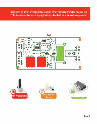
directions as some components are more easily soldered from the back of the PCB. Also remember steps highlighted in yellow feature polarized components.
1

Page 4
STEP BY STEP INSTRUCTIONS For this kit all components will be placed on the top of the board. However, read each part’s specific
0.1uF capacitors: Install the three 0.1uF capacitors. These capacitors will have a number designation of “104.” Install these capacitors the same way as the others.
7
0.47uF capacitors: Install the four 0.47uF capacitors. These will have a number designation of “474”. Install these capacitors the same way as the others.
8
1uF capacitors: Install the three 1uF capacitors. These will have a number designation of “105”. Install these capacitors the same way as the others.9
ON/STBY switch: Install the ON/STBY switch. Polarity is not important. Push it all the way into the holes, flip the board over and solder in place.12
1000uF capacitor: Install the 1000uF capacitor. This is the bigger of the two blue cans and is marked “1000uF”. Install in the same manner as in step 10. Again, polarity is critical!
11
100uF capacitor: Install the 100uF capacitor. You should have 2 capacitors left: both of them are bluish sort of cans with a white stripes down the side. Take the one marked “100uF” and insert the lead with the white strip into the negative hole, marked with “-.” Polarity is critical for this item, so make sure you put the right lead into the right hole.
10
WORKING ON THE TOP OF THE BOARD:

Page 5
1000uF Capacitors
1uF Capacitors X 3
9
100uF Capacitors
12ON/STBY Switch
TOP
0.1uF CapacitorsX 3
70.47uF Capacitors
X 4
8
directions as some components are more easily soldered from the back of the PCB. Also remember steps highlighted in yellow feature polarized components.
10 11
Page 6
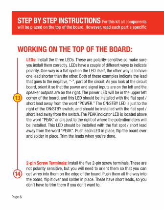
LEDs: Install the three LEDs. These are polarity-sensitive so make sure you install them correctly. LEDs have a couple of different ways to indicate polarity. One way is a flat spot on the LED itself, the other way is to have one lead shorter than the other. Both of these examples indicate the lead that goes to the negative, “-”, part of the circuit. As you look at the circuit board, orient it so that the power and signal inputs are on the left and the speaker outputs are on the right. The power LED will be in the upper left corner of the board, and this LED should be installed with the flat spot / short lead away from the word “POWER.” The ON/STBY LED is just to the right of the ON/STBY switch, and should be installed with the flat spot / short lead away from the switch. The PEAK indicator LED is located above the word “PEAK” and is just to the right of where the potentiometers will be installed. This LED should be installed with the flat spot / short lead away from the word “PEAK”. Push each LED in place, flip the board over and solder in place. Trim the leads when you’re done.
2-pin Screw Terminals: Install the five 2-pin screw terminals. These are not polarity sensitive, but you will need to orient them so that you can get wires into them on the edge of the board. Push them all the way into the board, flip it over and solder in place. These have short leads, so you don’t have to trim them if you don’t want to.
14
WORKING ON THE TOP OF THE BOARD:
STEP BY STEP INSTRUCTIONS For this kit all components will be placed on the top of the board. However, read each part’s specific
13

LEDs X 3
13
Page 7
TOP
2-Pin Screw Terminals X 5
14
directions as some components are more easily soldered from the back of the PCB. Also remember steps highlighted in yellow feature polarized components.

Page 8
WORKING ON THE TOP OF THE BOARD:10K Potentiometers: Install the two 10K potentiometers. These only fit one way, and they’ll be a little snug. Push them all the way into the board, flip it over and solder in place. Trim leads if you wish, but it’s not necessary.
15
Stand-offs and Screws: Mount stand-offs and screws to the corners of the amplifier board so that the stand-offs protrude from the back and away from the heat sink.
17
STA540 Amplifier Chip and Heat Sink: Install the STA540 amplifier chip and heat sink. The bottom of the heat sink is identified by two solder posts that stick out from one end. You are going to mount the STA540 amplifier chip so that its leads are facing the same end as those two posts. Take some heat sink compound and smear it on the back of the STA540 and also to the heat sink where the two parts will mate. Now line up the bolt hole in the heat sink with the bolt hole in the STA540, stick them together and secure them loosely with the included nut and bolt (make it tight enough to hold them in place, but not so tight that they won’t move). Install the heat sink and STA540 together onto the circuit board. On the back of the board, solder the posts on the heat sink to the board first. This will take some extra heating as there is more mass to solder, so be patient with this step and don’t rush it. Then tighten the nut and bolt holding the two parts together. Lastly, solder the 15 pins of the STA540 on the back of the board.
16
STEP BY STEP INSTRUCTIONS For this kit all components will be placed on the top of the board. However, read each part’s specific
Page 9
10K Potentiometers
15Stand-offs and
Screws
17STA540
Amplifier Chip
16
directions as some components are more easily soldered from the back of the PCB. Also remember steps highlighted in yellow feature polarized components.
TOP
Page 10
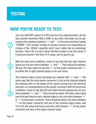
NOW YOU’RE READY TO TEST:
1
Turn the ON/STBY switch to STBY and turn the potentiometers all the way counter-clockwise. With a DVM, or any other ohmmeter you’ve got, measure the resistance between “+” and “-” on the screw terminal marked “POWER”. This number is likely to bounce around a bit depending on charge of the 1000uF capacitor and if your meter has an autorange function. That’s OK. It’s just critical that the number is not zero ohms. If it bounces around in the tens-of-K range, you’re good to go.
3
The channel output screw terminals are marked with “+” and “-” the same way that the main power connector is, but on the channel outputs the marking refer to the phase of the signal coming from the terminal and bear no correspondence to the power connector. With the same test conditions, check to see that left and right channel outputs are not zero ohms between “+” and “-”. They should be about 126 ohms. Also make sure that each lead on each channel output is not zero ohms between “+” or “-” on the power connector. There should be about 333 ohms between “-” on the power connector and any of the channel output leads, and 10’s of K (the value will bounce around a bit) between “+” on the power connector and any of the output channel leads.
2With the same test conditions, check to see that left and right channel inputs are not zero ohms between “+” and “-”. They should be between 9K and 10K. Also check to see that “+” on the power connector and “+” on either left or right channel inputs is not zero ohms.
TESTING
Page 11
4
Now you’re ready for the big one. Attach a signal source to your input screw terminals, speakers to your output terminals and 12V to the power terminal. The power LED should be on. Turn the ON/STBY switch to ON, and the corresponding LED should turn on. Slowly turn the potentiometers clockwise to suit (probably up to 11). Now you’re rocking!

© SparkFun Electronics, Inc. All Rights Reserved. The SparkFun Audio Amp Kit (KIT-09612) features, specifications, system requirements, and availability are subject to change without notice. All other trademarks contained herein are the property of their respective owners.
The STA540 Power AmplifierThe STA540 is the heart and soul of the audio amp kit. This features four independent channels and has all the pins broken out for easy access. This chip is fairly rugged, so you don’t need to be super careful as you solder it, but try not to melt the casing with your iron!
Soldering It is normal for the handle of the soldering iron to heat up a bit. Hold it like a pencil and move your hand further away from the tip if the heat is uncomfortable. The solder smokes because of the rosin inside the solder burning off. It’s not harmful, but if it really bothers you, blow it out of the way with a small fan.
LEDsLight emitting diodes (LEDs) are like light bulbs, but much smaller and more efficient.
Polarization:
Tips and Hints
Some components are polarized and have to be installed with that in mind. The steps involving polarized components are marked in yellow.