
Audi of America, Inc.2011-2012 MY Audi R8/R8 Spyder Dear Audi Dealer Principal, Service Manager, and...
41
24U8/K9 USA Audi of America, Inc. 3800 Hamlin Road Auburn Hills, MI 48326 +1 248 754 5000 www.audiusa.com Audi of America, Inc. Date: June 2012 Subject: Customer Satisfaction Campaign 24U8 Engine Wiring Harness Overlay & ECM Programming 2011-2012 MY Audi R8/R8 Spyder Dear Audi Dealer Principal, Service Manager, and Parts Manager: We would like to inform you of Customer Satisfaction Campaign 24U8. Please refer to the attached Campaign Data Sheet for additional information. If you have any questions or require additional assistance, please contact Warranty. As always, any press inquiries should be directed to Audi Public Relations. Audi Product Compliance Attachment: Campaign Data Sheet (1) SB-10044942-3432
Transcript of Audi of America, Inc.2011-2012 MY Audi R8/R8 Spyder Dear Audi Dealer Principal, Service Manager, and...
24U8/K9 USA
Audi of America, Inc. 3800 Hamlin Road Auburn Hills, MI 48326 +1 248 754 5000 www.audiusa.com
Audi of America, Inc.
Date: June 2012
Subject: Customer Satisfaction Campaign 24U8 Engine Wiring Harness Overlay & ECM Programming 2011-2012 MY Audi R8/R8 Spyder Dear Audi Dealer Principal, Service Manager, and Parts Manager: We would like to inform you of Customer Satisfaction Campaign 24U8. Please refer to the attached Campaign Data Sheet for additional information.
If you have any questions or require additional assistance, please contact Warranty. As always, any press inquiries should be directed to Audi Public Relations.
Audi Product Compliance
Attachment: Campaign Data Sheet (1)
SB-10044942-3432
IMPORTANT! To ensure that ALL of your personnel are aware of this action before receiving questions from any customer, please share this information with ALL personnel who have campaign-related responsibilities, including service writers, technicians, parts employees, warranty administrators, etc. See the campaign circular on ElsaWeb for the most current repair information. Refer to the campaign circular for complete repair and claiming instructions.
CAMPAIGN DATA SHEET
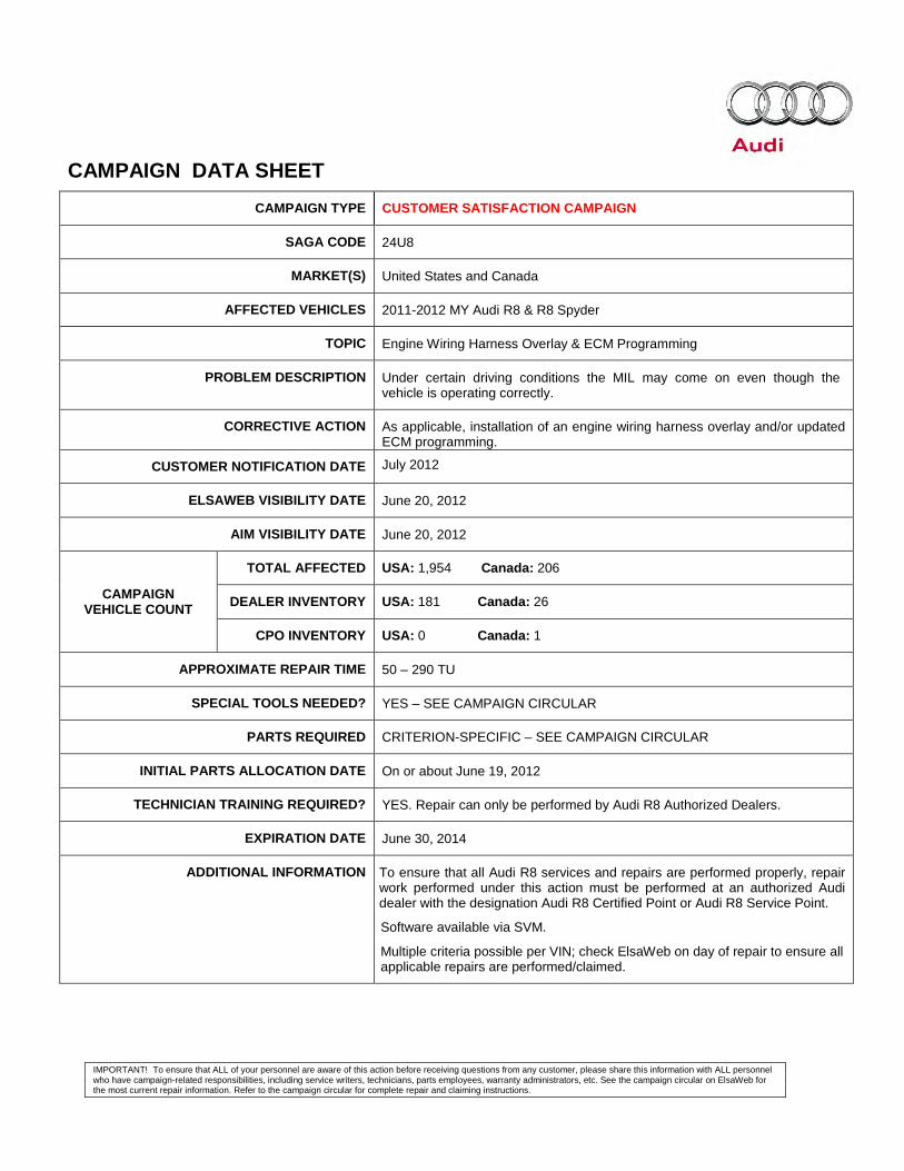
CAMPAIGN TYPE CUSTOMER SATISFACTION CAMPAIGN
SAGA CODE 24U8
MARKET(S) United States and Canada
AFFECTED VEHICLES 2011-2012 MY Audi R8 & R8 Spyder
TOPIC Engine Wiring Harness Overlay & ECM Programming
PROBLEM DESCRIPTION Under certain driving conditions the MIL may come on even though the vehicle is operating correctly.
CORRECTIVE ACTION As applicable, installation of an engine wiring harness overlay and/or updated ECM programming.
CUSTOMER NOTIFICATION DATE July 2012
ELSAWEB VISIBILITY DATE June 20, 2012
AIM VISIBILITY DATE June 20, 2012
CAMPAIGN VEHICLE COUNT
TOTAL AFFECTED USA: 1,954 Canada: 206
DEALER INVENTORY USA: 181 Canada: 26
CPO INVENTORY USA: 0 Canada: 1
APPROXIMATE REPAIR TIME 50 – 290 TU
SPECIAL TOOLS NEEDED? YES – SEE CAMPAIGN CIRCULAR
PARTS REQUIRED CRITERION-SPECIFIC – SEE CAMPAIGN CIRCULAR
INITIAL PARTS ALLOCATION DATE On or about June 19, 2012
TECHNICIAN TRAINING REQUIRED? YES. Repair can only be performed by Audi R8 Authorized Dealers.
EXPIRATION DATE June 30, 2014
ADDITIONAL INFORMATION To ensure that all Audi R8 services and repairs are performed properly, repair work performed under this action must be performed at an authorized Audi dealer with the designation Audi R8 Certified Point or Audi R8 Service Point.
Software available via SVM.
Multiple criteria possible per VIN; check ElsaWeb on day of repair to ensure all applicable repairs are performed/claimed.
IMPORTANT! This FAQ is intended to provide supplementary information regarding this action. For additional information, please refer to the campaign circular posted on ElsaWeb and ServiceNet. To ensure that ALL of your personnel are aware of this action before receiving questions from any customer, please share this information with ALL personnel who have campaign-related responsibilities, including service writers, technicians, parts employees, warranty administrators, etc.
Page 1 of 1 24U8/K9
Frequently Asked Questions (FAQ) Customer Satisfaction Campaign 24U8
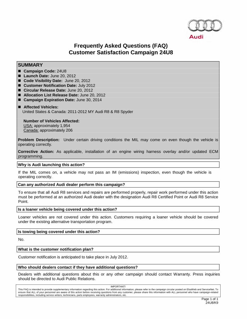
SUMMARY
Campaign Code: 24U8 Launch Date: June 20, 2012 Code Visibility Date: June 20, 2012 Customer Notification Date: July 2012 Circular Release Date: June 20, 2012 Allocation List Release Date: June 20, 2012 Campaign Expiration Date: June 30, 2014
Affected Vehicles: United States & Canada: 2011-2012 MY Audi R8 & R8 Spyder Number of Vehicles Affected: USA: approximately 1,954 Canada: approximately 206 Problem Description: Under certain driving conditions the MIL may come on even though the vehicle is operating correctly.
Corrective Action: As applicable, installation of an engine wiring harness overlay and/or updated ECM programming.
Why is Audi launching this action?
If the MIL comes on, a vehicle may not pass an IM (emissions) inspection, even though the vehicle is operating correctly.
Can any authorized Audi dealer perform this campaign?
To ensure that all Audi R8 services and repairs are performed properly, repair work performed under this action must be performed at an authorized Audi dealer with the designation Audi R8 Certified Point or Audi R8 Service Point.
Is a loaner vehicle being covered under this action?
Loaner vehicles are not covered under this action. Customers requiring a loaner vehicle should be covered under the existing alternative transportation program.
Is towing being covered under this action?
No.
What is the customer notification plan?
Customer notification is anticipated to take place in July 2012.
Who should dealers contact if they have additional questions? Dealers with additional questions about this or any other campaign should contact Warranty. Press inquiries should be directed to Audi Public Relations.
IMPORTANT INFORMATION Please inform and provide a copy of this document to every person in your dealership with campaign-related responsibilities, including Service, Parts and Accounting personnel. By law, dealers must correct, prior to delivery for sale or lease, any vehicle that fails to comply with an applicable Federal Motor Vehicle Safety Standard or that contains a defect relating to motor vehicle safety. If you have questions regarding this or any other campaign, please contact Warranty
The information in this document is intended for use only by skilled technicians who have the proper tools, equipment and training to correctly and safely maintain your vehicle. These procedures are not intended to be attempted by “do-it-yourselfers,” and you should not assume this document applies to your vehicle, or that your vehicle has the condition described. To determine whether this information applies, contact an authorized Audi dealer. 2012 Audi of America, LLC and Audi Canada. All Rights Reserved. June 2012 24U8/K9 Page 1 of 38
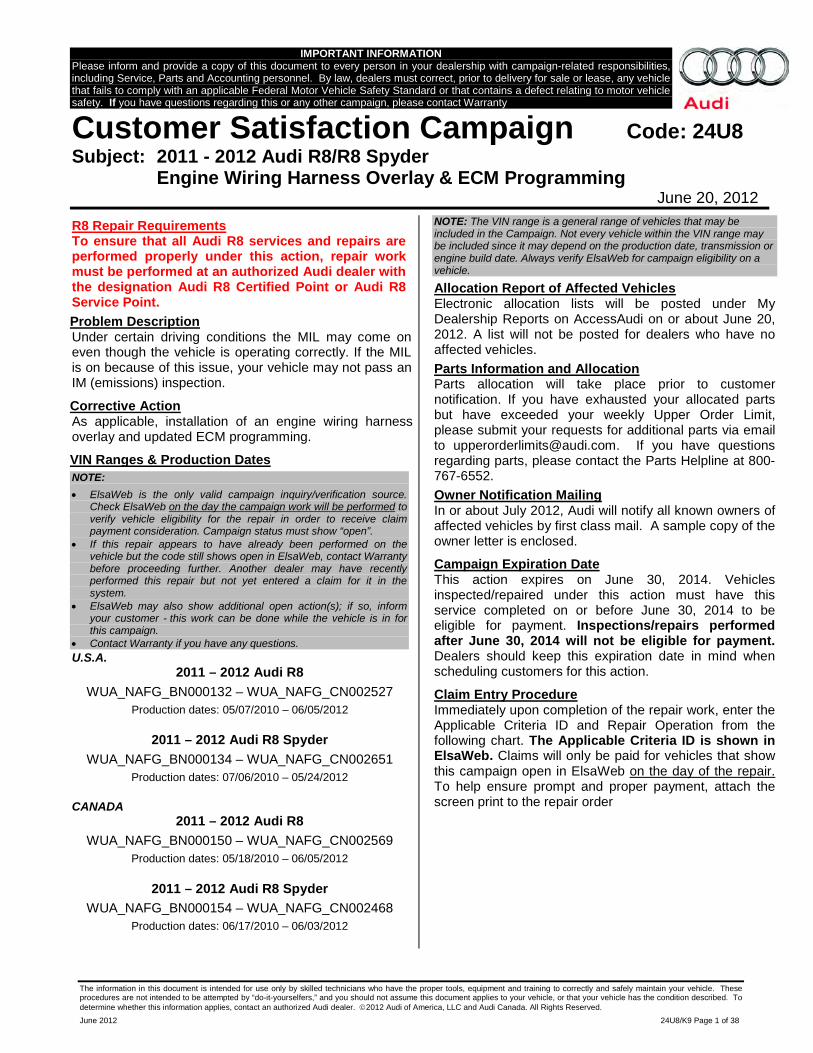
Customer Satisfaction Campaign Code: 24U8 Subject: 2011 - 2012 Audi R8/R8 Spyder Engine Wiring Harness Overlay & ECM Programming June 20, 2012
R8 Repair Requirements To ensure that all Audi R8 services and repairs are performed properly under this action, repair work must be performed at an authorized Audi dealer with the designation Audi R8 Certified Point or Audi R8 Service Point. Problem Description Under certain driving conditions the MIL may come on even though the vehicle is operating correctly. If the MIL is on because of this issue, your vehicle may not pass an IM (emissions) inspection.
Corrective Action As applicable, installation of an engine wiring harness overlay and updated ECM programming.
VIN Ranges & Production Dates NOTE: • ElsaWeb is the only valid campaign inquiry/verification source.
Check ElsaWeb on the day the campaign work will be performed to verify vehicle eligibility for the repair in order to receive claim payment consideration. Campaign status must show “open”.
• If this repair appears to have already been performed on the vehicle but the code still shows open in ElsaWeb, contact Warranty before proceeding further. Another dealer may have recently performed this repair but not yet entered a claim for it in the system.
• ElsaWeb may also show additional open action(s); if so, inform your customer - this work can be done while the vehicle is in for this campaign.
• Contact Warranty if you have any questions. U.S.A.
2011 – 2012 Audi R8 WUA_NAFG_BN000132 – WUA_NAFG_CN002527
Production dates: 05/07/2010 – 06/05/2012
2011 – 2012 Audi R8 Spyder WUA_NAFG_BN000134 – WUA_NAFG_CN002651
Production dates: 07/06/2010 – 05/24/2012
CANADA 2011 – 2012 Audi R8
WUA_NAFG_BN000150 – WUA_NAFG_CN002569 Production dates: 05/18/2010 – 06/05/2012
2011 – 2012 Audi R8 Spyder WUA_NAFG_BN000154 – WUA_NAFG_CN002468
Production dates: 06/17/2010 – 06/03/2012
NOTE: The VIN range is a general range of vehicles that may be included in the Campaign. Not every vehicle within the VIN range may be included since it may depend on the production date, transmission or engine build date. Always verify ElsaWeb for campaign eligibility on a vehicle. Allocation Report of Affected Vehicles Electronic allocation lists will be posted under My Dealership Reports on AccessAudi on or about June 20, 2012. A list will not be posted for dealers who have no affected vehicles. Parts Information and Allocation Parts allocation will take place prior to customer notification. If you have exhausted your allocated parts but have exceeded your weekly Upper Order Limit, please submit your requests for additional parts via email to [email protected]. If you have questions regarding parts, please contact the Parts Helpline at 800-767-6552. Owner Notification Mailing In or about July 2012, Audi will notify all known owners of affected vehicles by first class mail. A sample copy of the owner letter is enclosed.
Campaign Expiration Date This action expires on June 30, 2014. Vehicles inspected/repaired under this action must have this service completed on or before June 30, 2014 to be eligible for payment. Inspections/repairs performed after June 30, 2014 will not be eligible for payment. Dealers should keep this expiration date in mind when scheduling customers for this action.
Claim Entry Procedure Immediately upon completion of the repair work, enter the Applicable Criteria ID and Repair Operation from the following chart. The Applicable Criteria ID is shown in ElsaWeb. Claims will only be paid for vehicles that show this campaign open in ElsaWeb on the day of the repair. To help ensure prompt and proper payment, attach the screen print to the repair order
The information in this document is intended for use only by skilled technicians who have the proper tools, equipment and training to correctly and safely maintain your vehicle. These procedures are not intended to be attempted by “do-it-yourselfers,” and you should not assume this document applies to your vehicle, or that your vehicle has the condition described. To determine whether this information applies, contact an authorized Audi dealer. 2012 Audi of America LLC and Audi Canada. All Rights Reserved.
June 2012 24U8/K9 Page 2 of 38
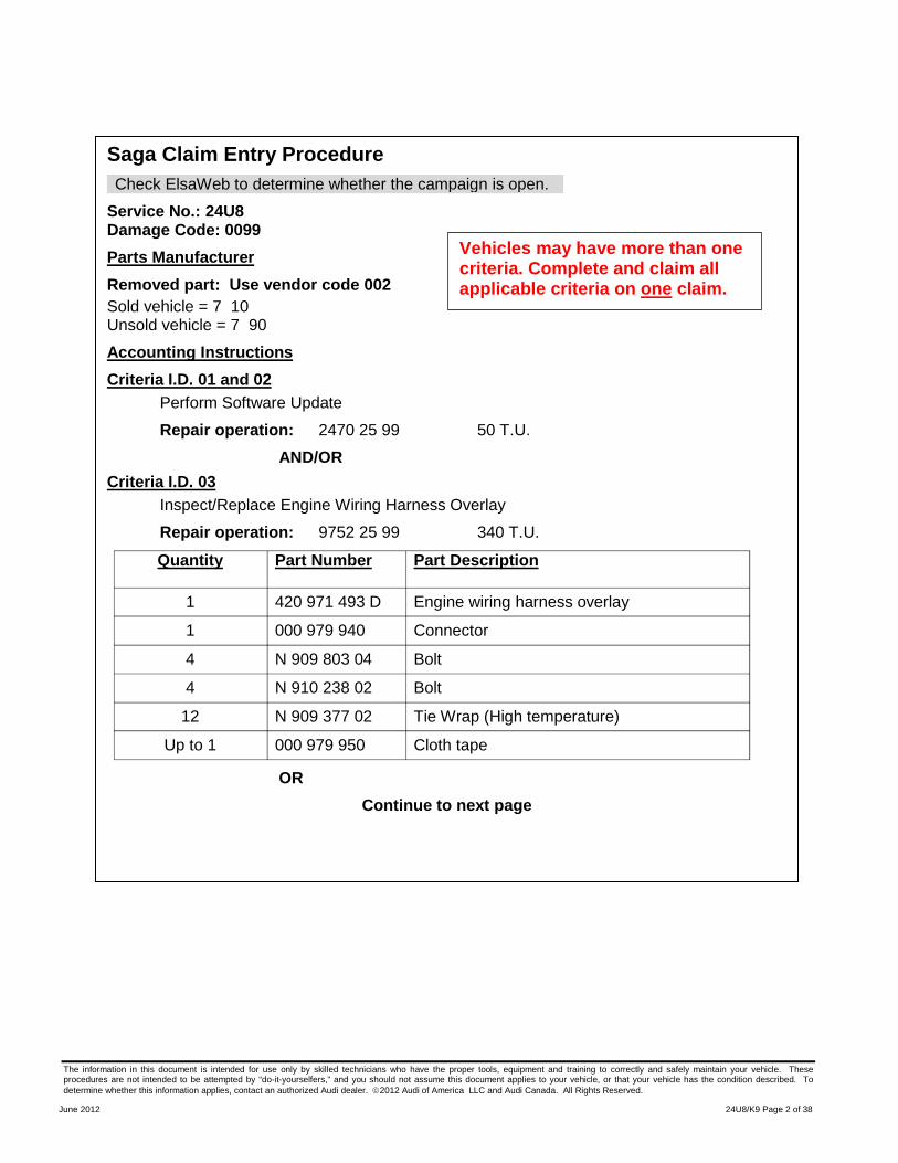
Saga Claim Entry Procedure Check ElsaWeb to determine whether the campaign is open.
Service No.: 24U8 Damage Code: 0099 Parts Manufacturer Removed part: Use vendor code 002 Sold vehicle = 7 10 Unsold vehicle = 7 90
Accounting Instructions Criteria I.D. 01 and 02
Perform Software Update
Repair operation: 2470 25 99 50 T.U. AND/OR
Criteria I.D. 03 Inspect/Replace Engine Wiring Harness Overlay
Repair operation: 9752 25 99 340 T.U. Quantity Part Number Part Description
1 420 971 493 D Engine wiring harness overlay
1 000 979 940 Connector
4 N 909 803 04 Bolt
4 N 910 238 02 Bolt
12 N 909 377 02 Tie Wrap (High temperature)
Up to 1 000 979 950 Cloth tape
OR Continue to next page
Vehicles may have more than one criteria. Complete and claim all applicable criteria on one claim.
The information in this document is intended for use only by skilled technicians who have the proper tools, equipment and training to correctly and safely maintain your vehicle. These procedures are not intended to be attempted by “do-it-yourselfers,” and you should not assume this document applies to your vehicle, or that your vehicle has the condition described. To determine whether this information applies, contact an authorized Audi dealer. 2012 Audi of America LLC and Audi Canada. All Rights Reserved.
June 2012 24U8/K9 Page 3 of 38
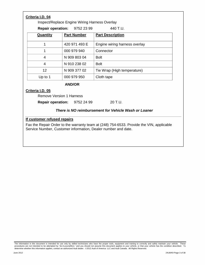
Criteria I.D. 04 Inspect/Replace Engine Wiring Harness Overlay
Repair operation: 9752 23 99 440 T.U.
Quantity Part Number Part Description
1 420 971 493 E Engine wiring harness overlay
1 000 979 940 Connector
4 N 909 803 04 Bolt
4 N 910 238 02 Bolt
12 N 909 377 02 Tie Wrap (High temperature)
Up to 1 000 979 950 Cloth tape
AND/OR Criteria I.D. 05
Remove Version 1 Harness
Repair operation: 9752 24 99 20 T.U.
There is NO reimbursement for Vehicle Wash or Loaner
If customer refused repairs Fax the Repair Order to the warranty team at (248) 754-6533. Provide the VIN, applicable Service Number, Customer information, Dealer number and date.
The information in this document is intended for use only by skilled technicians who have the proper tools, equipment and training to correctly and safely maintain your vehicle. These procedures are not intended to be attempted by “do-it-yourselfers,” and you should not assume this document applies to your vehicle, or that your vehicle has the condition described. To determine whether this information applies, contact an authorized Audi dealer. 2012 Audi of America LLC and Audi Canada. All Rights Reserved.
June 2012 24U8/K9 Page 4 of 38
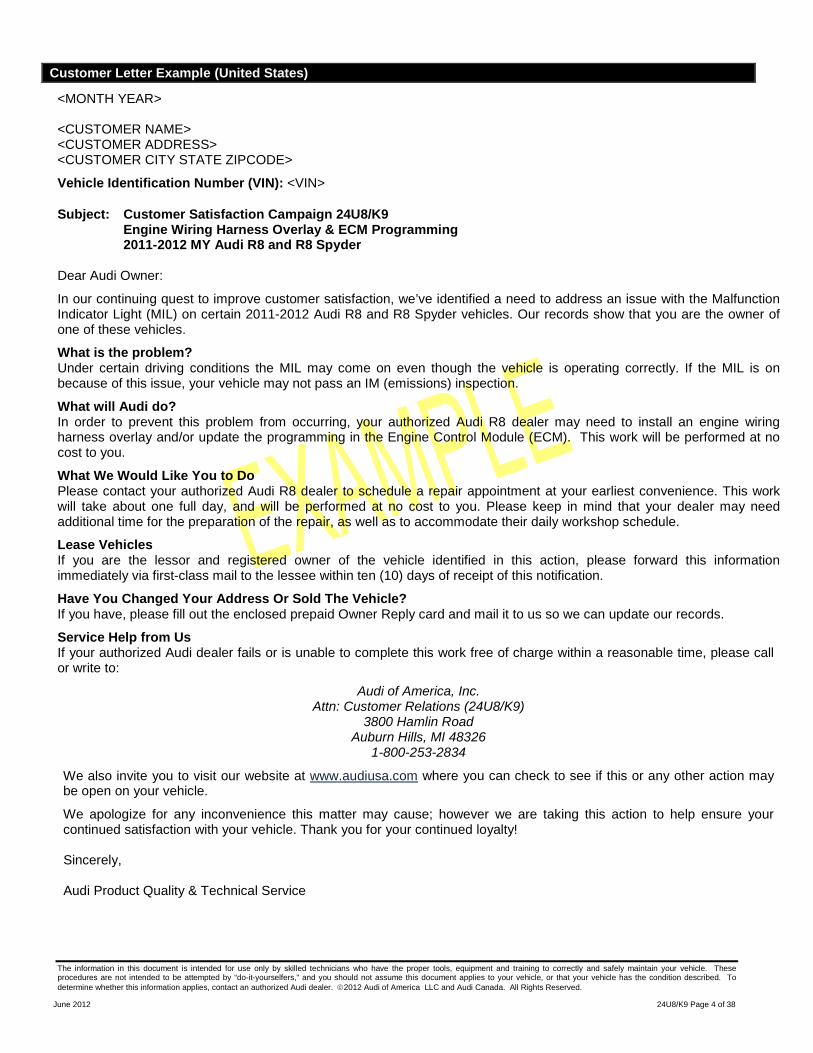
Customer Letter Example (United States)
<MONTH YEAR> <CUSTOMER NAME> <CUSTOMER ADDRESS> <CUSTOMER CITY STATE ZIPCODE>
Vehicle Identification Number (VIN): <VIN>
Subject: Customer Satisfaction Campaign 24U8/K9 Engine Wiring Harness Overlay & ECM Programming 2011-2012 MY Audi R8 and R8 Spyder
Dear Audi Owner:
In our continuing quest to improve customer satisfaction, we’ve identified a need to address an issue with the Malfunction Indicator Light (MIL) on certain 2011-2012 Audi R8 and R8 Spyder vehicles. Our records show that you are the owner of one of these vehicles.
What is the problem? Under certain driving conditions the MIL may come on even though the vehicle is operating correctly. If the MIL is on because of this issue, your vehicle may not pass an IM (emissions) inspection.
What will Audi do? In order to prevent this problem from occurring, your authorized Audi R8 dealer may need to install an engine wiring harness overlay and/or update the programming in the Engine Control Module (ECM). This work will be performed at no cost to you.
What We Would Like You to Do Please contact your authorized Audi R8 dealer to schedule a repair appointment at your earliest convenience. This work will take about one full day, and will be performed at no cost to you. Please keep in mind that your dealer may need additional time for the preparation of the repair, as well as to accommodate their daily workshop schedule.
Lease Vehicles If you are the lessor and registered owner of the vehicle identified in this action, please forward this information immediately via first-class mail to the lessee within ten (10) days of receipt of this notification.
Have You Changed Your Address Or Sold The Vehicle? If you have, please fill out the enclosed prepaid Owner Reply card and mail it to us so we can update our records.
Service Help from Us If your authorized Audi dealer fails or is unable to complete this work free of charge within a reasonable time, please call or write to:
Audi of America, Inc. Attn: Customer Relations (24U8/K9)
3800 Hamlin Road Auburn Hills, MI 48326
1-800-253-2834
We also invite you to visit our website at www.audiusa.com where you can check to see if this or any other action may be open on your vehicle.
We apologize for any inconvenience this matter may cause; however we are taking this action to help ensure your continued satisfaction with your vehicle. Thank you for your continued loyalty! Sincerely, Audi Product Quality & Technical Service
The information in this document is intended for use only by skilled technicians who have the proper tools, equipment and training to correctly and safely maintain your vehicle. These procedures are not intended to be attempted by “do-it-yourselfers,” and you should not assume this document applies to your vehicle, or that your vehicle has the condition described. To determine whether this information applies, contact an authorized Audi dealer. 2012 Audi of America LLC and Audi Canada. All Rights Reserved.
June 2012 24U8/K9 Page 5 of 38
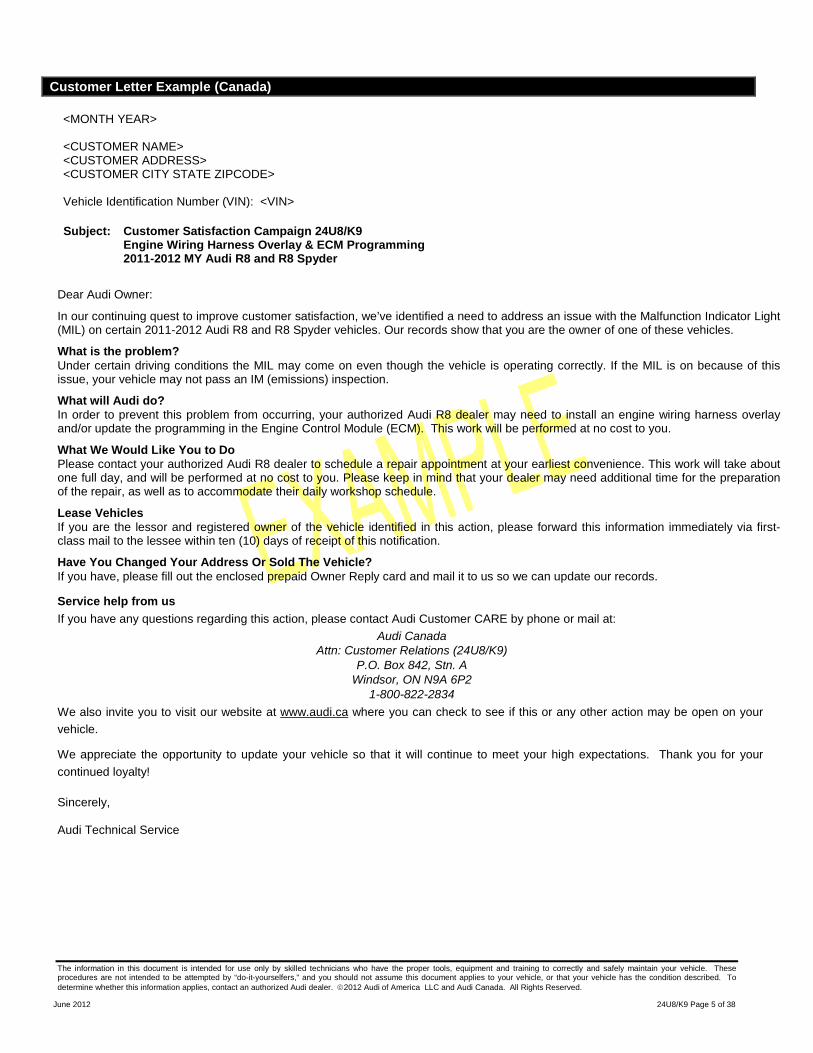
Customer Letter Example (Canada)
<MONTH YEAR> <CUSTOMER NAME> <CUSTOMER ADDRESS> <CUSTOMER CITY STATE ZIPCODE> Vehicle Identification Number (VIN): <VIN>
Subject: Customer Satisfaction Campaign 24U8/K9 Engine Wiring Harness Overlay & ECM Programming 2011-2012 MY Audi R8 and R8 Spyder
Dear Audi Owner:
In our continuing quest to improve customer satisfaction, we’ve identified a need to address an issue with the Malfunction Indicator Light (MIL) on certain 2011-2012 Audi R8 and R8 Spyder vehicles. Our records show that you are the owner of one of these vehicles.
What is the problem? Under certain driving conditions the MIL may come on even though the vehicle is operating correctly. If the MIL is on because of this issue, your vehicle may not pass an IM (emissions) inspection.
What will Audi do? In order to prevent this problem from occurring, your authorized Audi R8 dealer may need to install an engine wiring harness overlay and/or update the programming in the Engine Control Module (ECM). This work will be performed at no cost to you.
What We Would Like You to Do Please contact your authorized Audi R8 dealer to schedule a repair appointment at your earliest convenience. This work will take about one full day, and will be performed at no cost to you. Please keep in mind that your dealer may need additional time for the preparation of the repair, as well as to accommodate their daily workshop schedule.
Lease Vehicles If you are the lessor and registered owner of the vehicle identified in this action, please forward this information immediately via first-class mail to the lessee within ten (10) days of receipt of this notification.
Have You Changed Your Address Or Sold The Vehicle? If you have, please fill out the enclosed prepaid Owner Reply card and mail it to us so we can update our records.
Service help from us If you have any questions regarding this action, please contact Audi Customer CARE by phone or mail at:
Audi Canada Attn: Customer Relations (24U8/K9)
P.O. Box 842, Stn. A Windsor, ON N9A 6P2
1-800-822-2834 We also invite you to visit our website at www.audi.ca where you can check to see if this or any other action may be open on your vehicle.
We appreciate the opportunity to update your vehicle so that it will continue to meet your high expectations. Thank you for your continued loyalty! Sincerely, Audi Technical Service
The information in this document is intended for use only by skilled technicians who have the proper tools, equipment and training to correctly and safely maintain your vehicle. These procedures are not intended to be attempted by “do-it-yourselfers,” and you should not assume this document applies to your vehicle, or that your vehicle has the condition described. To determine whether this information applies, contact an authorized Audi dealer. 2012 Audi of America LLC and Audi Canada. All Rights Reserved.
June 2012 24U8/K9 Page 6 of 38
Campaign Work Procedure 24U8 Customer Satisfaction Campaign
If there are questions regarding the work procedure: • U.S. dealers, contact Warranty • Canadian dealers, open an ATA ticket using concern group “Compliance/Recall Assistance (C)”
Required Parts: Criteria I.D. 03 (Coupe)
Quantity Part Number Part Description
1 420 971 493 D Engine wiring harness overlay
1 000 979 940 Connector
4 N 909 803 04 Sheer bolt with locking compound
4 N 910 238 02 Sheer bolt without locking compound
12 N 909 377 02 Tie Wrap (High Temperature)
Up to 1 000 979 950 Cloth tape
Shop supply -- Shrink tubing
Shop supply N 103 113 04 Yellow tape in VAS 1978 B Tool kit
Shop supply -- Silicone sealant
Criteria I.D. 04 (Spyder)
Quantity Part Number Part Description
1 420 971 493 E Engine wiring harness overlay
1 000 979 940 Connector
4 N 909 803 04 Sheer bolt with locking compound
4 N 910 238 02 Sheer bolt without locking compound
12 N 909 377 02 Tie Wrap (High Temperature)
Up to 1 000 979 950 Cloth tape
Shop supply -- Shrink tubing
Shop supply N 103 113 04 Yellow tape in VAS 1978 B Tool kit
Shop supply -- Silicone sealant
The information in this document is intended for use only by skilled technicians who have the proper tools, equipment and training to correctly and safely maintain your vehicle. These procedures are not intended to be attempted by “do-it-yourselfers,” and you should not assume this document applies to your vehicle, or that your vehicle has the condition described. To determine whether this information applies, contact an authorized Audi dealer. 2012 Audi of America LLC and Audi Canada. All Rights Reserved.
June 2012 24U8/K9 Page 7 of 38
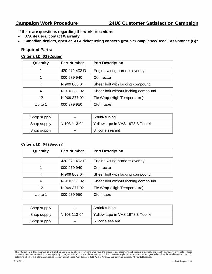
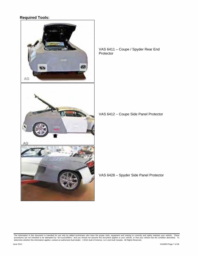
Required Tools:
VAS 6411 – Coupe / Spyder Rear End Protector
VAS 6412 – Coupe Side Panel Protector
VAS 6428 – Spyder Side Panel Protector
The information in this document is intended for use only by skilled technicians who have the proper tools, equipment and training to correctly and safely maintain your vehicle. These procedures are not intended to be attempted by “do-it-yourselfers,” and you should not assume this document applies to your vehicle, or that your vehicle has the condition described. To determine whether this information applies, contact an authorized Audi dealer. 2012 Audi of America LLC and Audi Canada. All Rights Reserved.
June 2012 24U8/K9 Page 8 of 38
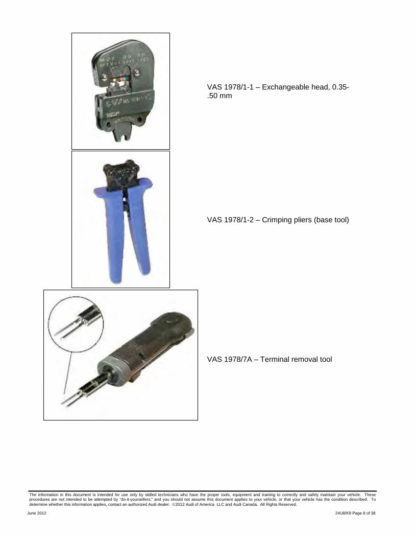
VAS 1978/1-1 – Exchangeable head, 0.35-.50 mm
VAS 1978/1-2 – Crimping pliers (base tool)
VAS 1978/7A – Terminal removal tool
The information in this document is intended for use only by skilled technicians who have the proper tools, equipment and training to correctly and safely maintain your vehicle. These procedures are not intended to be attempted by “do-it-yourselfers,” and you should not assume this document applies to your vehicle, or that your vehicle has the condition described. To determine whether this information applies, contact an authorized Audi dealer. 2012 Audi of America LLC and Audi Canada. All Rights Reserved.
June 2012 24U8/K9 Page 9 of 38
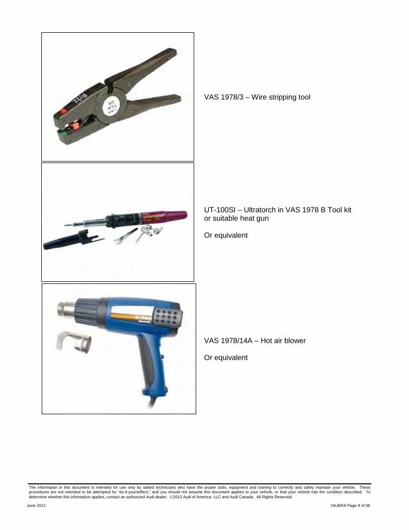
VAS 1978/3 – Wire stripping tool
UT-100SI – Ultratorch in VAS 1978 B Tool kit or suitable heat gun Or equivalent
VAS 1978/14A – Hot air blower Or equivalent
The information in this document is intended for use only by skilled technicians who have the proper tools, equipment and training to correctly and safely maintain your vehicle. These procedures are not intended to be attempted by “do-it-yourselfers,” and you should not assume this document applies to your vehicle, or that your vehicle has the condition described. To determine whether this information applies, contact an authorized Audi dealer. 2012 Audi of America LLC and Audi Canada. All Rights Reserved.
June 2012 24U8/K9 Page 10 of 38
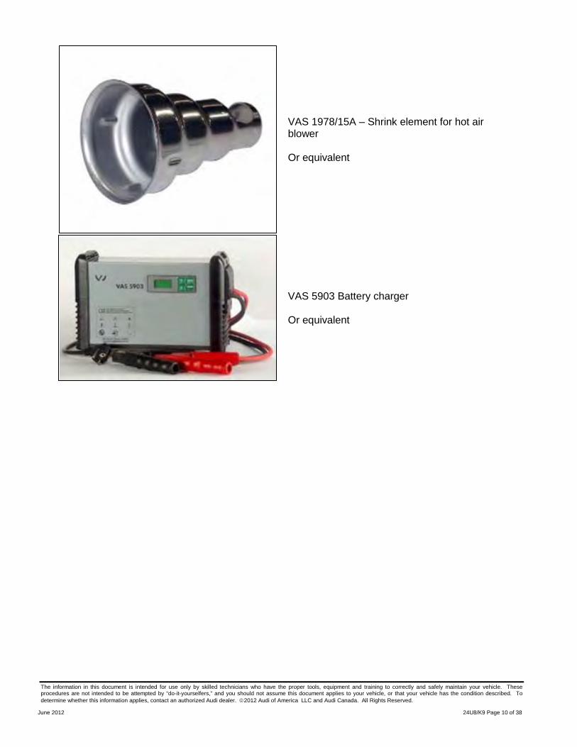
VAS 1978/15A – Shrink element for hot air blower Or equivalent
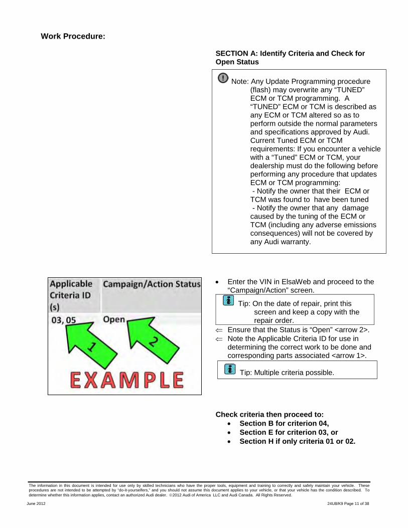
VAS 5903 Battery charger Or equivalent
The information in this document is intended for use only by skilled technicians who have the proper tools, equipment and training to correctly and safely maintain your vehicle. These procedures are not intended to be attempted by “do-it-yourselfers,” and you should not assume this document applies to your vehicle, or that your vehicle has the condition described. To determine whether this information applies, contact an authorized Audi dealer. 2012 Audi of America LLC and Audi Canada. All Rights Reserved.
June 2012 24U8/K9 Page 11 of 38
Work Procedure:
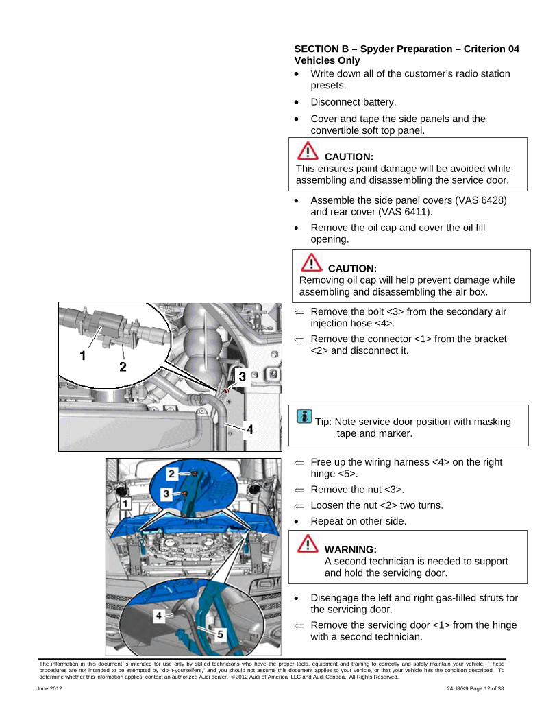
SECTION A: Identify Criteria and Check for Open Status
• Enter the VIN in ElsaWeb and proceed to the “Campaign/Action” screen.
Tip: On the date of repair, print this screen and keep a copy with the repair order.
⇐ Ensure that the Status is “Open” <arrow 2>. ⇐ Note the Applicable Criteria ID for use in
determining the correct work to be done and corresponding parts associated <arrow 1>.
Check criteria then proceed to: • Section B for criterion 04, • Section E for criterion 03, or • Section H if only criteria 01 or 02.
Note: Any Update Programming procedure (flash) may overwrite any “TUNED” ECM or TCM programming. A “TUNED” ECM or TCM is described as any ECM or TCM altered so as to perform outside the normal parameters and specifications approved by Audi. Current Tuned ECM or TCM requirements: If you encounter a vehicle with a “Tuned” ECM or TCM, your dealership must do the following before performing any procedure that updates ECM or TCM programming: - Notify the owner that their ECM or TCM was found to have been tuned - Notify the owner that any damage caused by the tuning of the ECM or TCM (including any adverse emissions consequences) will not be covered by any Audi warranty.
Tip: Multiple criteria possible.
The information in this document is intended for use only by skilled technicians who have the proper tools, equipment and training to correctly and safely maintain your vehicle. These procedures are not intended to be attempted by “do-it-yourselfers,” and you should not assume this document applies to your vehicle, or that your vehicle has the condition described. To determine whether this information applies, contact an authorized Audi dealer. 2012 Audi of America LLC and Audi Canada. All Rights Reserved.
June 2012 24U8/K9 Page 12 of 38
SECTION B – Spyder Preparation – Criterion 04 Vehicles Only
• Write down all of the customer’s radio station presets.
• Disconnect battery. • Cover and tape the side panels and the
convertible soft top panel.
• Assemble the side panel covers (VAS 6428) and rear cover (VAS 6411).
• Remove the oil cap and cover the oil fill opening.
⇐ Remove the bolt <3> from the secondary air injection hose <4>.
⇐ Remove the connector <1> from the bracket <2> and disconnect it.
⇐ Free up the wiring harness <4> on the right
hinge <5>. ⇐ Remove the nut <3>. ⇐ Loosen the nut <2> two turns. • Repeat on other side. • Disengage the left and right gas-filled struts for
the servicing door. ⇐ Remove the servicing door <1> from the hinge
with a second technician.
WARNING: A second technician is needed to support and hold the servicing door.
Tip: Note service door position with masking tape and marker.
CAUTION: This ensures paint damage will be avoided while assembling and disassembling the service door.
CAUTION: Removing oil cap will help prevent damage while assembling and disassembling the air box.
The information in this document is intended for use only by skilled technicians who have the proper tools, equipment and training to correctly and safely maintain your vehicle. These procedures are not intended to be attempted by “do-it-yourselfers,” and you should not assume this document applies to your vehicle, or that your vehicle has the condition described. To determine whether this information applies, contact an authorized Audi dealer. 2012 Audi of America LLC and Audi Canada. All Rights Reserved.
June 2012 24U8/K9 Page 13 of 38
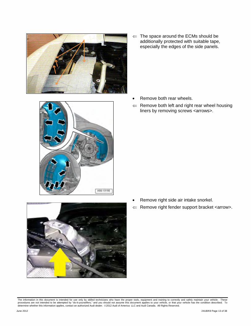
⇐ The space around the ECMs should be additionally protected with suitable tape, especially the edges of the side panels.
• Remove both rear wheels.
⇐ Remove both left and right rear wheel housing liners by removing screws <arrows>.
• Remove right side air intake snorkel.
⇐ Remove right fender support bracket <arrow>.
The information in this document is intended for use only by skilled technicians who have the proper tools, equipment and training to correctly and safely maintain your vehicle. These procedures are not intended to be attempted by “do-it-yourselfers,” and you should not assume this document applies to your vehicle, or that your vehicle has the condition described. To determine whether this information applies, contact an authorized Audi dealer. 2012 Audi of America LLC and Audi Canada. All Rights Reserved.
June 2012 24U8/K9 Page 14 of 38
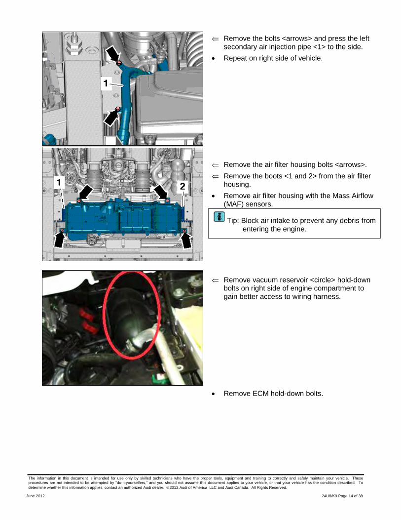
⇐ Remove the bolts <arrows> and press the left secondary air injection pipe <1> to the side.
• Repeat on right side of vehicle.
⇐ Remove the air filter housing bolts <arrows>. ⇐ Remove the boots <1 and 2> from the air filter
housing. • Remove air filter housing with the Mass Airflow
(MAF) sensors. •
⇐ Remove vacuum reservoir <circle> hold-down
bolts on right side of engine compartment to gain better access to wiring harness.
• Remove ECM hold-down bolts.
Tip: Block air intake to prevent any debris from entering the engine.
The information in this document is intended for use only by skilled technicians who have the proper tools, equipment and training to correctly and safely maintain your vehicle. These procedures are not intended to be attempted by “do-it-yourselfers,” and you should not assume this document applies to your vehicle, or that your vehicle has the condition described. To determine whether this information applies, contact an authorized Audi dealer. 2012 Audi of America LLC and Audi Canada. All Rights Reserved.
June 2012 24U8/K9 Page 15 of 38
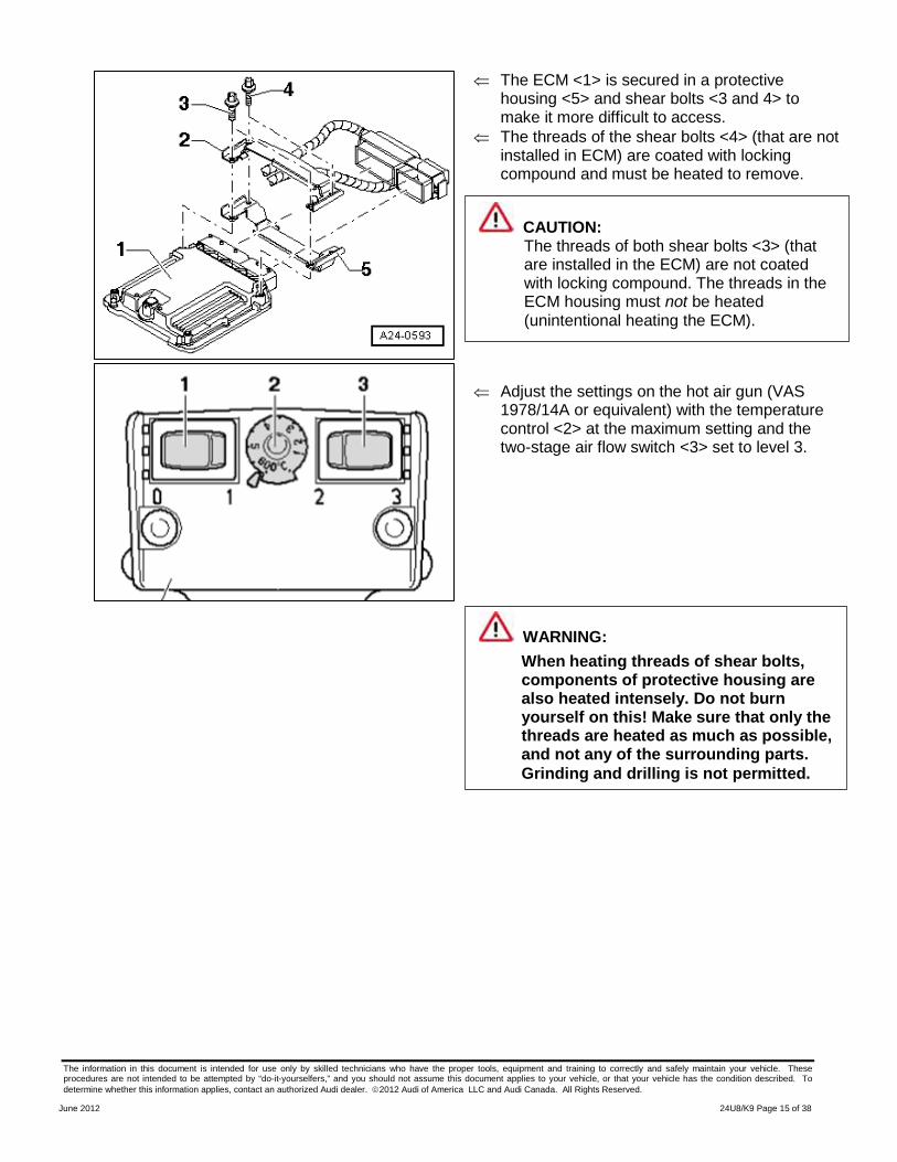
⇐ The ECM <1> is secured in a protective housing <5> and shear bolts <3 and 4> to make it more difficult to access.
⇐ The threads of the shear bolts <4> (that are not installed in ECM) are coated with locking compound and must be heated to remove.
⇐ Adjust the settings on the hot air gun (VAS
1978/14A or equivalent) with the temperature control <2> at the maximum setting and the two-stage air flow switch <3> set to level 3.
CAUTION: The threads of both shear bolts <3> (that are installed in the ECM) are not coated with locking compound. The threads in the ECM housing must not be heated (unintentional heating the ECM).
WARNING: When heating threads of shear bolts, components of protective housing are also heated intensely. Do not burn yourself on this! Make sure that only the threads are heated as much as possible, and not any of the surrounding parts.
Grinding and drilling is not permitted.
The information in this document is intended for use only by skilled technicians who have the proper tools, equipment and training to correctly and safely maintain your vehicle. These procedures are not intended to be attempted by “do-it-yourselfers,” and you should not assume this document applies to your vehicle, or that your vehicle has the condition described. To determine whether this information applies, contact an authorized Audi dealer. 2012 Audi of America LLC and Audi Canada. All Rights Reserved.
June 2012 24U8/K9 Page 16 of 38
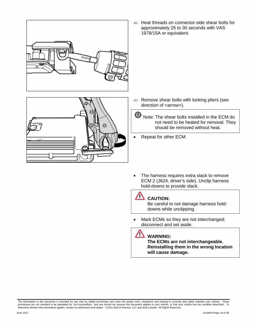
⇐ Heat threads on connector-side shear bolts for approximately 25 to 30 seconds with VAS 1978/15A or equivalent.
⇐ Remove shear bolts with locking pliers (see
direction of <arrow>).
• Repeat for other ECM.
• The harness requires extra slack to remove ECM 2 (J624, driver’s side). Unclip harness hold-downs to provide slack.
• Mark ECMs so they are not interchanged; disconnect and set aside.
Note: The shear bolts installed in the ECM do not need to be heated for removal. They should be removed without heat.
CAUTION: Be careful to not damage harness hold-downs while unclipping.
WARNING: The ECMs are not interchangeable. Reinstalling them in the wrong location will cause damage.
The information in this document is intended for use only by skilled technicians who have the proper tools, equipment and training to correctly and safely maintain your vehicle. These procedures are not intended to be attempted by “do-it-yourselfers,” and you should not assume this document applies to your vehicle, or that your vehicle has the condition described. To determine whether this information applies, contact an authorized Audi dealer. 2012 Audi of America LLC and Audi Canada. All Rights Reserved.
June 2012 24U8/K9 Page 17 of 38
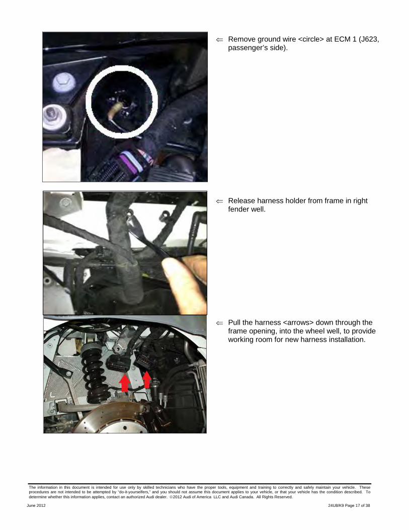
⇐ Remove ground wire <circle> at ECM 1 (J623, passenger’s side).
⇐ Release harness holder from frame in right
fender well.
⇐ Pull the harness <arrows> down through the frame opening, into the wheel well, to provide working room for new harness installation.
The information in this document is intended for use only by skilled technicians who have the proper tools, equipment and training to correctly and safely maintain your vehicle. These procedures are not intended to be attempted by “do-it-yourselfers,” and you should not assume this document applies to your vehicle, or that your vehicle has the condition described. To determine whether this information applies, contact an authorized Audi dealer. 2012 Audi of America LLC and Audi Canada. All Rights Reserved.
June 2012 24U8/K9 Page 18 of 38
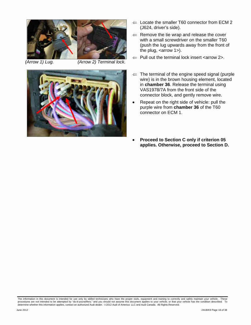
(Arrow 1) Lug. (Arrow 2) Terminal lock.
⇐ Locate the smaller T60 connector from ECM 2 (J624, driver’s side).
⇐ Remove the tie wrap and release the cover with a small screwdriver on the smaller T60 (push the lug upwards away from the front of the plug, <arrow 1>).
⇐ Pull out the terminal lock insert <arrow 2>.
⇐ The terminal of the engine speed signal (purple wire) is in the brown housing element, located in chamber 36. Release the terminal using VAS1978/7A from the front side of the connector block, and gently remove wire.
• Repeat on the right side of vehicle: pull the purple wire from chamber 36 of the T60 connector on ECM 1.
• Proceed to Section C only if criterion 05 applies. Otherwise, proceed to Section D.
The information in this document is intended for use only by skilled technicians who have the proper tools, equipment and training to correctly and safely maintain your vehicle. These procedures are not intended to be attempted by “do-it-yourselfers,” and you should not assume this document applies to your vehicle, or that your vehicle has the condition described. To determine whether this information applies, contact an authorized Audi dealer. 2012 Audi of America LLC and Audi Canada. All Rights Reserved.
June 2012 24U8/K9 Page 19 of 38
SECTION C – Remove Spyder Version 1 Harness – Criterion 05 Vehicles Only
• Follow the version 1 harness back from ECM 2 and remove any tie wraps that were installed securing overlay to main engine harness. Do this all the way to the D90 connection point.
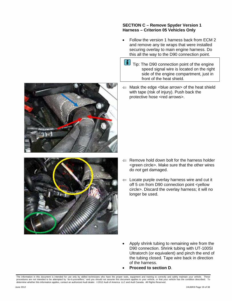
⇐ Mask the edge <blue arrow> of the heat shield with tape (risk of injury). Push back the protective hose <red arrows>.
⇐ Remove hold down bolt for the harness holder <green circle>. Make sure that the other wires do not get damaged.
⇐ Locate purple overlay harness wire and cut it
off 5 cm from D90 connection point <yellow circle>. Discard the overlay harness; it will no longer be used.
• Apply shrink tubing to remaining wire from the D90 connection. Shrink tubing with UT-100SI Ultratorch (or equivalent) and pinch the end of the tubing closed. Tape wire back in direction of the harness.
• Proceed to section D.
Tip: The D90 connection point of the engine speed signal wire is located on the right side of the engine compartment, just in front of the heat shield.
The information in this document is intended for use only by skilled technicians who have the proper tools, equipment and training to correctly and safely maintain your vehicle. These procedures are not intended to be attempted by “do-it-yourselfers,” and you should not assume this document applies to your vehicle, or that your vehicle has the condition described. To determine whether this information applies, contact an authorized Audi dealer. 2012 Audi of America LLC and Audi Canada. All Rights Reserved.
June 2012 24U8/K9 Page 20 of 38
SECTION D: Installing Version 2 Harness on Spyder – Criterion 04 Vehicles Only
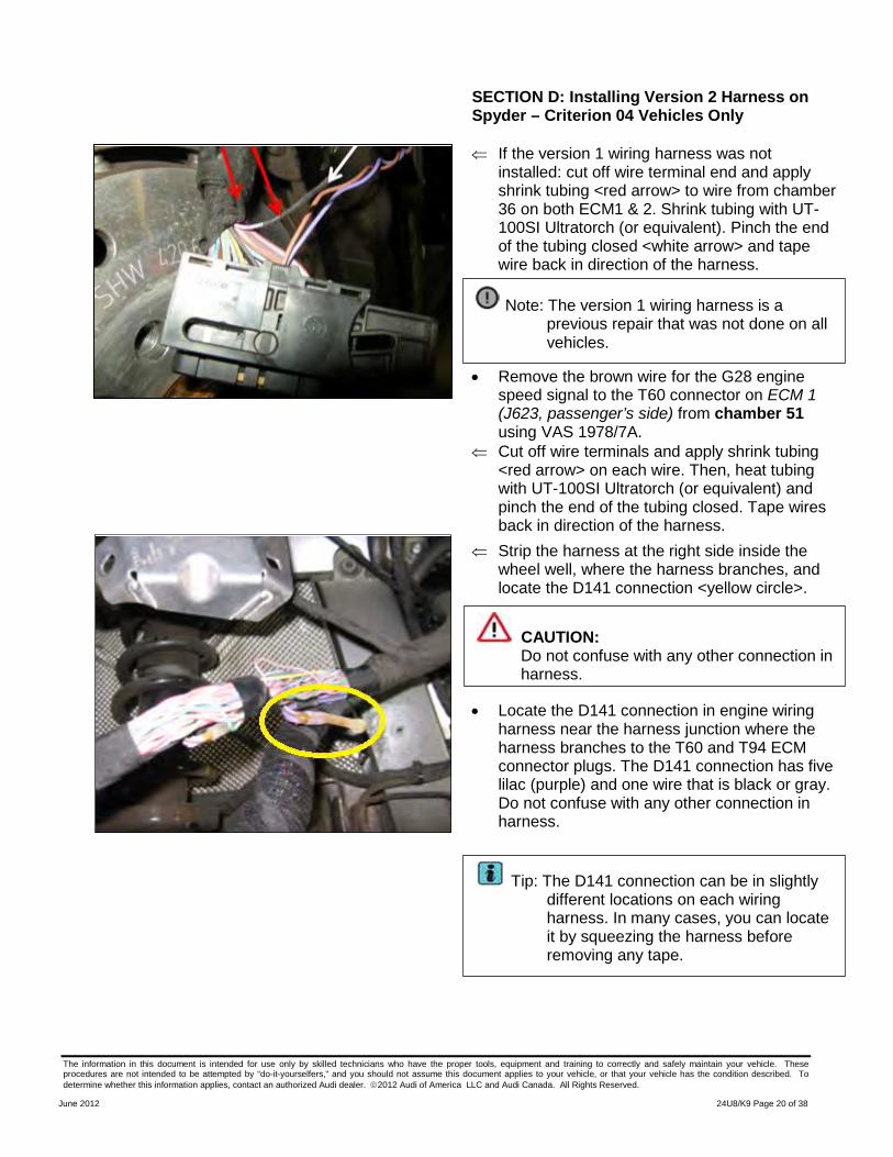
⇐ If the version 1 wiring harness was not installed: cut off wire terminal end and apply shrink tubing <red arrow> to wire from chamber 36 on both ECM1 & 2. Shrink tubing with UT-100SI Ultratorch (or equivalent). Pinch the end of the tubing closed <white arrow> and tape wire back in direction of the harness.
• Remove the brown wire for the G28 engine
speed signal to the T60 connector on ECM 1 (J623, passenger’s side) from chamber 51 using VAS 1978/7A.
⇐ Cut off wire terminals and apply shrink tubing <red arrow> on each wire. Then, heat tubing with UT-100SI Ultratorch (or equivalent) and pinch the end of the tubing closed. Tape wires back in direction of the harness.
⇐ Strip the harness at the right side inside the wheel well, where the harness branches, and locate the D141 connection <yellow circle>.
• Locate the D141 connection in engine wiring harness near the harness junction where the harness branches to the T60 and T94 ECM connector plugs. The D141 connection has five lilac (purple) and one wire that is black or gray. Do not confuse with any other connection in harness.
Note: The version 1 wiring harness is a previous repair that was not done on all vehicles.
Tip: The D141 connection can be in slightly different locations on each wiring harness. In many cases, you can locate it by squeezing the harness before removing any tape.
CAUTION: Do not confuse with any other connection in harness.
The information in this document is intended for use only by skilled technicians who have the proper tools, equipment and training to correctly and safely maintain your vehicle. These procedures are not intended to be attempted by “do-it-yourselfers,” and you should not assume this document applies to your vehicle, or that your vehicle has the condition described. To determine whether this information applies, contact an authorized Audi dealer. 2012 Audi of America LLC and Audi Canada. All Rights Reserved.
June 2012 24U8/K9 Page 21 of 38
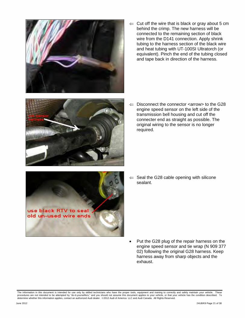
⇐ Cut off the wire that is black or gray about 5 cm behind the crimp. The new harness will be connected to the remaining section of black wire from the D141 connection. Apply shrink tubing to the harness section of the black wire and heat tubing with UT-100SI Ultratorch (or equivalent). Pinch the end of the tubing closed and tape back in direction of the harness.
⇐ Disconnect the connector <arrow> to the G28
engine speed sensor on the left side of the transmission bell housing and cut off the connecter end as straight as possible. The original wiring to the sensor is no longer required.
⇐ Seal the G28 cable opening with silicone
sealant.
• Put the G28 plug of the repair harness on the engine speed sensor and tie wrap (N 909 377 02) following the original G28 harness. Keep harness away from sharp objects and the exhaust.
The information in this document is intended for use only by skilled technicians who have the proper tools, equipment and training to correctly and safely maintain your vehicle. These procedures are not intended to be attempted by “do-it-yourselfers,” and you should not assume this document applies to your vehicle, or that your vehicle has the condition described. To determine whether this information applies, contact an authorized Audi dealer. 2012 Audi of America LLC and Audi Canada. All Rights Reserved.
June 2012 24U8/K9 Page 22 of 38
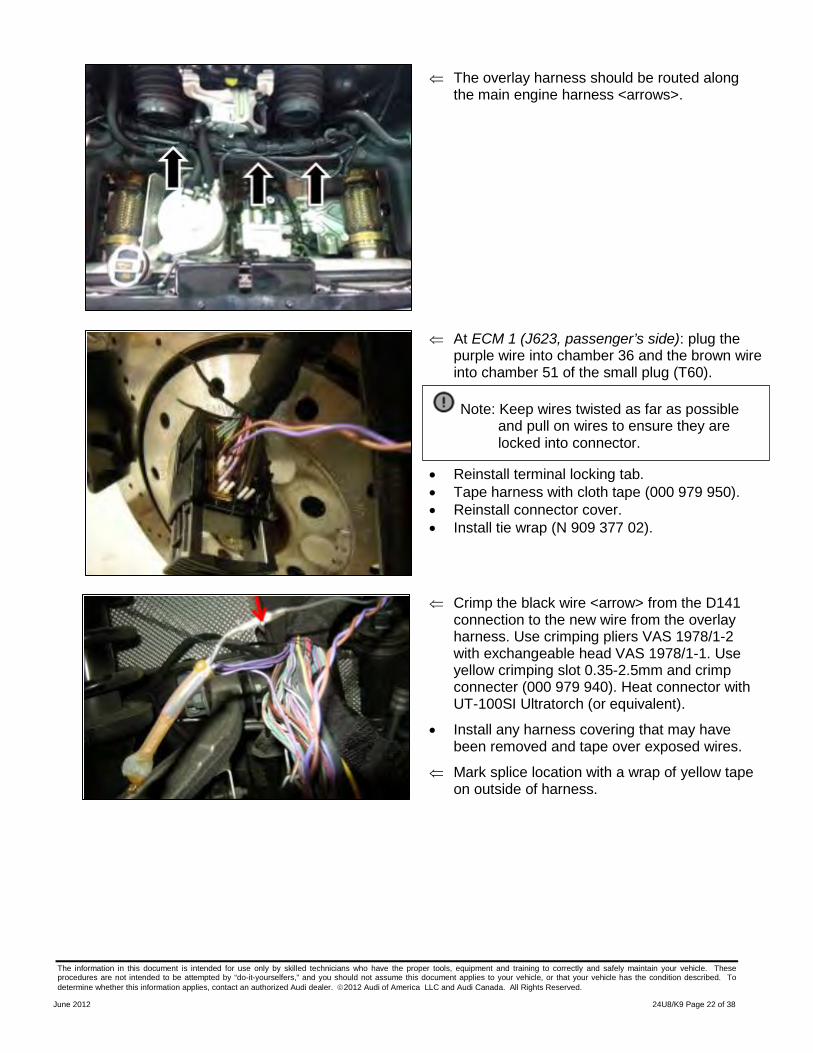
⇐ The overlay harness should be routed along the main engine harness <arrows>.
⇐ At ECM 1 (J623, passenger’s side): plug the
purple wire into chamber 36 and the brown wire into chamber 51 of the small plug (T60).
• Reinstall terminal locking tab. • Tape harness with cloth tape (000 979 950). • Reinstall connector cover. • Install tie wrap (N 909 377 02).
⇐ Crimp the black wire <arrow> from the D141
connection to the new wire from the overlay harness. Use crimping pliers VAS 1978/1-2 with exchangeable head VAS 1978/1-1. Use yellow crimping slot 0.35-2.5mm and crimp connecter (000 979 940). Heat connector with UT-100SI Ultratorch (or equivalent).
• Install any harness covering that may have been removed and tape over exposed wires.
⇐ Mark splice location with a wrap of yellow tape on outside of harness.
Note: Keep wires twisted as far as possible and pull on wires to ensure they are locked into connector.
The information in this document is intended for use only by skilled technicians who have the proper tools, equipment and training to correctly and safely maintain your vehicle. These procedures are not intended to be attempted by “do-it-yourselfers,” and you should not assume this document applies to your vehicle, or that your vehicle has the condition described. To determine whether this information applies, contact an authorized Audi dealer. 2012 Audi of America LLC and Audi Canada. All Rights Reserved.
June 2012 24U8/K9 Page 23 of 38
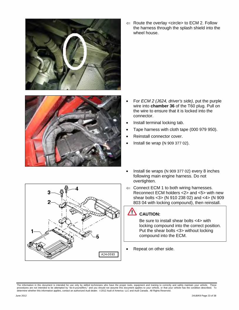
⇐ Route the overlay <circle> to ECM 2. Follow the harness through the splash shield into the wheel house.
• For ECM 2 (J624, driver’s side), put the purple
wire into chamber 36 of the T60 plug. Pull on the wire to ensure that it is locked into the connector.
• Install terminal locking tab. • Tape harness with cloth tape (000 979 950). • Reinstall connector cover. • Install tie wrap (N 909 377 02).
• Install tie wraps (N 909 377 02) every 8 inches following main engine harness. Do not overtighten.
⇐ Connect ECM 1 to both wiring harnesses. Reconnect ECM holders <2> and <5> with new shear bolts <3> (N 910 238 02) and <4> (N 909 803 04 with locking compound), then reinstall.
⇐ • Repeat on other side.
CAUTION: Be sure to install shear bolts <4> with locking compound into the correct position. Put the shear bolts <3> without locking compound into the ECM.
The information in this document is intended for use only by skilled technicians who have the proper tools, equipment and training to correctly and safely maintain your vehicle. These procedures are not intended to be attempted by “do-it-yourselfers,” and you should not assume this document applies to your vehicle, or that your vehicle has the condition described. To determine whether this information applies, contact an authorized Audi dealer. 2012 Audi of America LLC and Audi Canada. All Rights Reserved.
June 2012 24U8/K9 Page 24 of 38
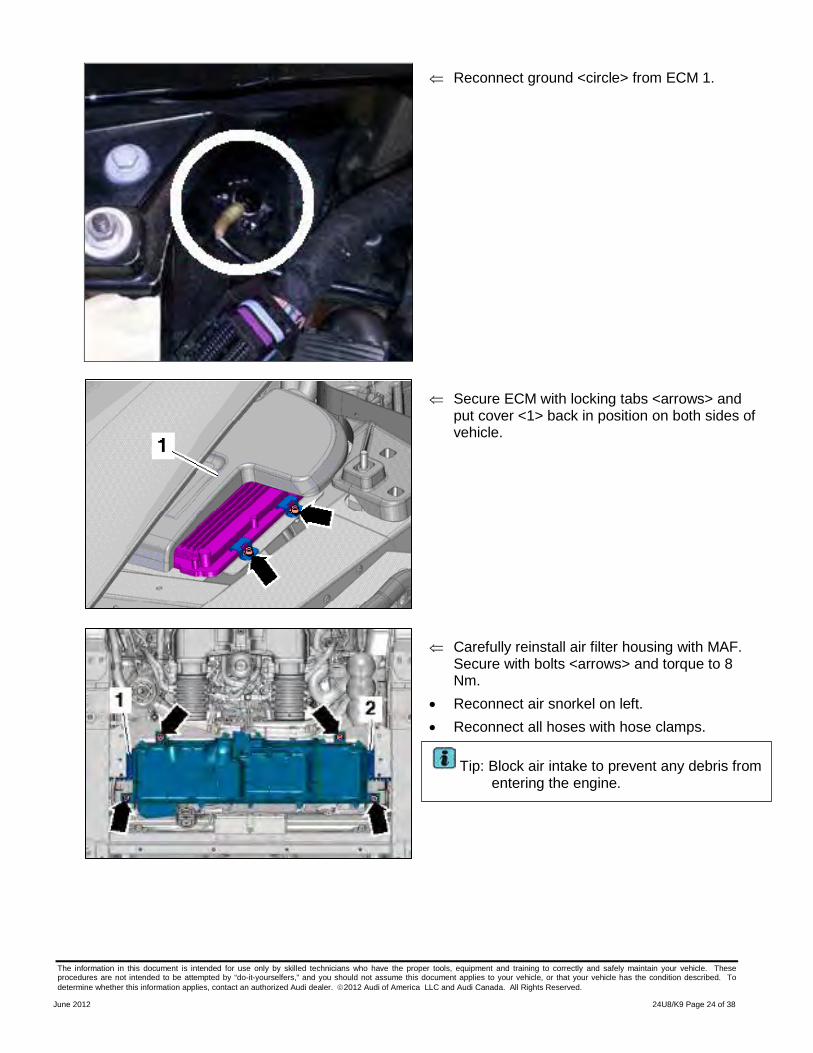
⇐ Reconnect ground <circle> from ECM 1.
⇐ Secure ECM with locking tabs <arrows> and
put cover <1> back in position on both sides of vehicle.
⇐ Carefully reinstall air filter housing with MAF.
Secure with bolts <arrows> and torque to 8 Nm.
• Reconnect air snorkel on left. • Reconnect all hoses with hose clamps.
Tip: Block air intake to prevent any debris from entering the engine.
The information in this document is intended for use only by skilled technicians who have the proper tools, equipment and training to correctly and safely maintain your vehicle. These procedures are not intended to be attempted by “do-it-yourselfers,” and you should not assume this document applies to your vehicle, or that your vehicle has the condition described. To determine whether this information applies, contact an authorized Audi dealer. 2012 Audi of America LLC and Audi Canada. All Rights Reserved.
June 2012 24U8/K9 Page 25 of 38
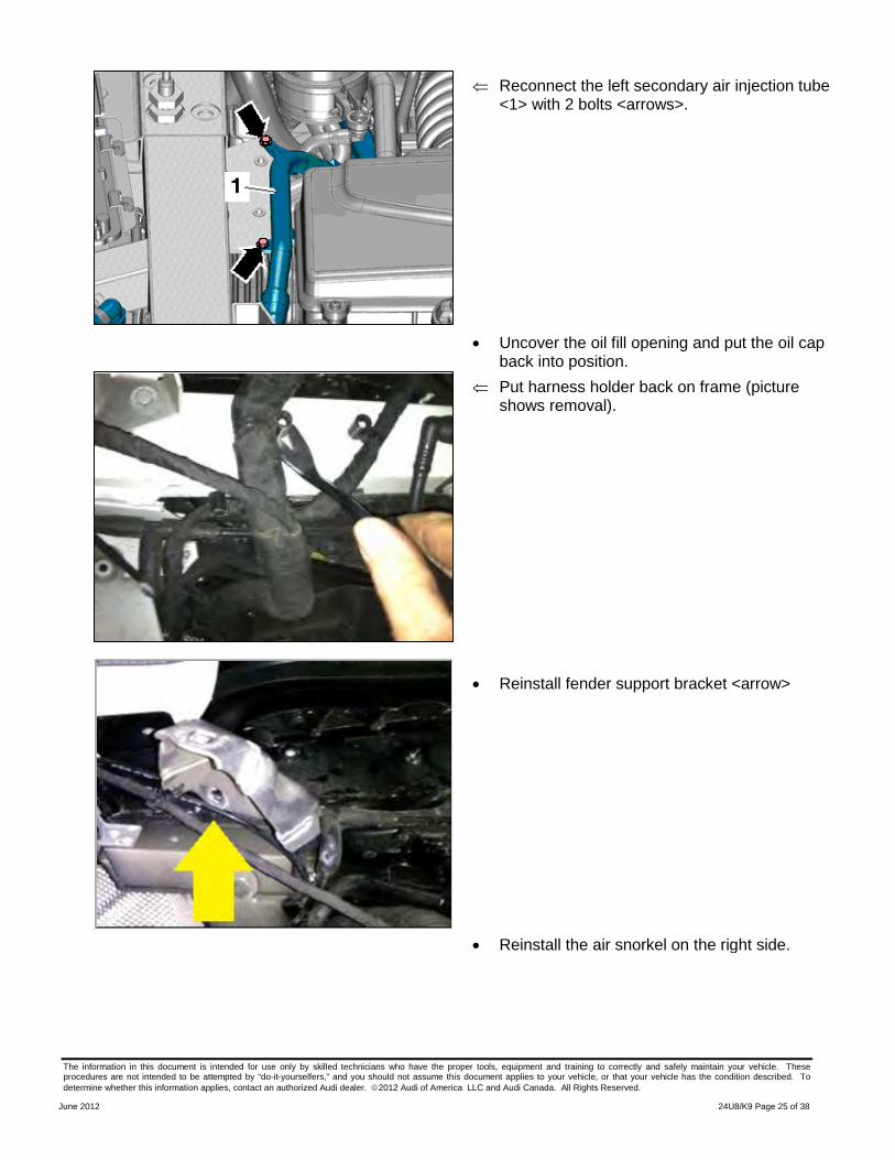
⇐ Reconnect the left secondary air injection tube <1> with 2 bolts <arrows>.
• Uncover the oil fill opening and put the oil cap back into position.
⇐ Put harness holder back on frame (picture shows removal).
• Reinstall fender support bracket <arrow>
• Reinstall the air snorkel on the right side.
The information in this document is intended for use only by skilled technicians who have the proper tools, equipment and training to correctly and safely maintain your vehicle. These procedures are not intended to be attempted by “do-it-yourselfers,” and you should not assume this document applies to your vehicle, or that your vehicle has the condition described. To determine whether this information applies, contact an authorized Audi dealer. 2012 Audi of America LLC and Audi Canada. All Rights Reserved.
June 2012 24U8/K9 Page 26 of 38
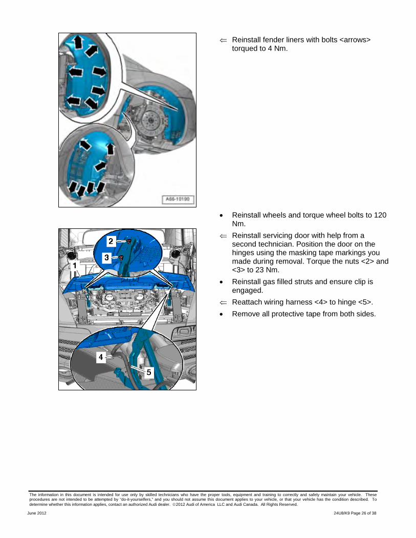
⇐ Reinstall fender liners with bolts <arrows> torqued to 4 Nm.
• Reinstall wheels and torque wheel bolts to 120 Nm.
⇐ Reinstall servicing door with help from a second technician. Position the door on the hinges using the masking tape markings you made during removal. Torque the nuts <2> and <3> to 23 Nm.
• Reinstall gas filled struts and ensure clip is engaged.
⇐ Reattach wiring harness <4> to hinge <5>. • Remove all protective tape from both sides.
The information in this document is intended for use only by skilled technicians who have the proper tools, equipment and training to correctly and safely maintain your vehicle. These procedures are not intended to be attempted by “do-it-yourselfers,” and you should not assume this document applies to your vehicle, or that your vehicle has the condition described. To determine whether this information applies, contact an authorized Audi dealer. 2012 Audi of America LLC and Audi Canada. All Rights Reserved.
June 2012 24U8/K9 Page 27 of 38
⇐ Reconnect connector <1>, then put back into bracket <2> ensuring that it is clipped into place.
⇐ Secure secondary air hose <4> with nut <3>.
• Remove protective covers (VAS 6411 and VAS 6428) and any remaining protective tape.
• Reconnect battery. • Re-set the customer’s preset radio stations and
window pinch protection. • Start engine and let idle for one minute to verify
vehicle is running correctly. • Proceed to Section H if vehicle meets
criterion 01. Otherwise, work complete.
SECTION E – Coupe Preparation – Criterion 03 Vehicles Only
• Write down all of the customer’s radio station presets.
• Disconnect battery. • Assemble the side panel covers (VAS 6412)
and rear cover (VAS 6411).
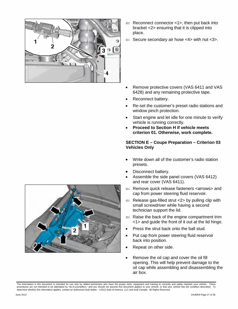
⇐ Remove quick release fasteners <arrows> and cap from power steering fluid reservoir.
⇐ Release gas-filled strut <2> by pulling clip with small screwdriver while having a second technician support the lid.
⇐ Raise the back of the engine compartment trim <1> and guide the front of it out at the lid hinge.
• Press the strut back onto the ball stud. • Put cap from power steering fluid reservoir
back into position. • Repeat on other side.
• Remove the oil cap and cover the oil fill opening. This will help prevent damage to the oil cap while assembling and disassembling the air box.
The information in this document is intended for use only by skilled technicians who have the proper tools, equipment and training to correctly and safely maintain your vehicle. These procedures are not intended to be attempted by “do-it-yourselfers,” and you should not assume this document applies to your vehicle, or that your vehicle has the condition described. To determine whether this information applies, contact an authorized Audi dealer. 2012 Audi of America LLC and Audi Canada. All Rights Reserved.
June 2012 24U8/K9 Page 28 of 38
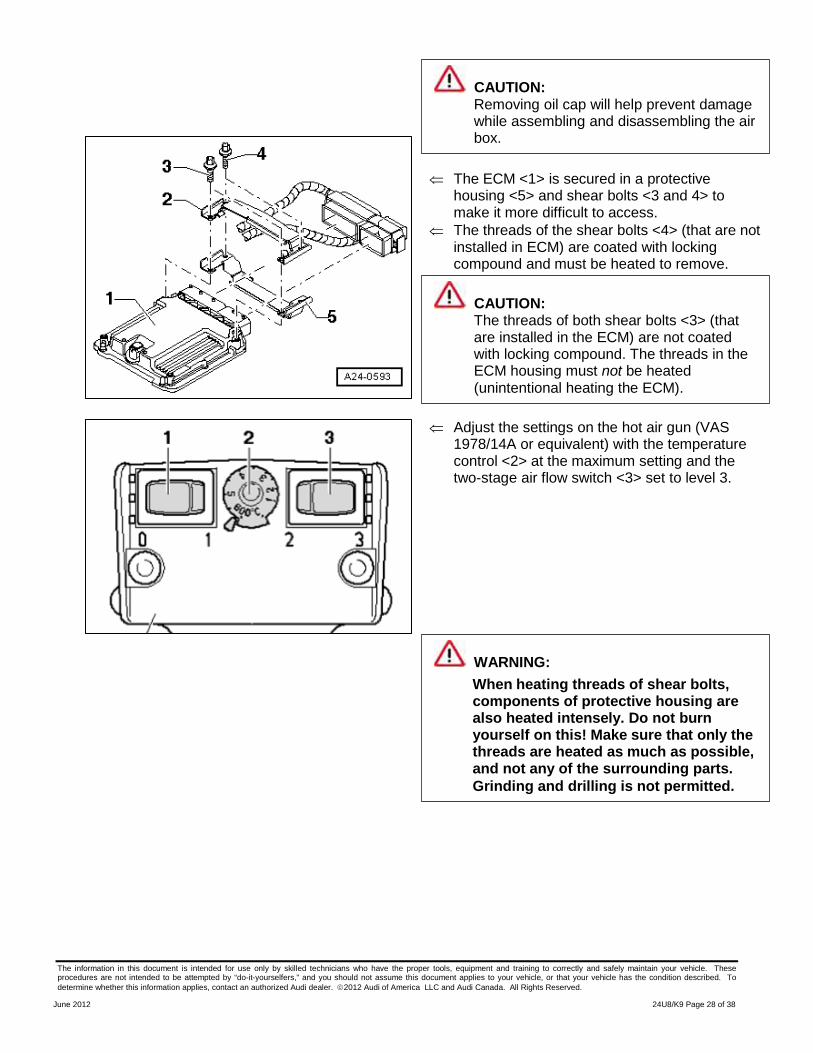
⇐ The ECM <1> is secured in a protective
housing <5> and shear bolts <3 and 4> to make it more difficult to access.
⇐ The threads of the shear bolts <4> (that are not installed in ECM) are coated with locking compound and must be heated to remove.
⇐ Adjust the settings on the hot air gun (VAS
1978/14A or equivalent) with the temperature control <2> at the maximum setting and the two-stage air flow switch <3> set to level 3.
CAUTION: The threads of both shear bolts <3> (that are installed in the ECM) are not coated with locking compound. The threads in the ECM housing must not be heated (unintentional heating the ECM).
CAUTION: Removing oil cap will help prevent damage while assembling and disassembling the air box.
WARNING: When heating threads of shear bolts, components of protective housing are also heated intensely. Do not burn yourself on this! Make sure that only the threads are heated as much as possible, and not any of the surrounding parts. Grinding and drilling is not permitted.
The information in this document is intended for use only by skilled technicians who have the proper tools, equipment and training to correctly and safely maintain your vehicle. These procedures are not intended to be attempted by “do-it-yourselfers,” and you should not assume this document applies to your vehicle, or that your vehicle has the condition described. To determine whether this information applies, contact an authorized Audi dealer. 2012 Audi of America LLC and Audi Canada. All Rights Reserved.
June 2012 24U8/K9 Page 29 of 38
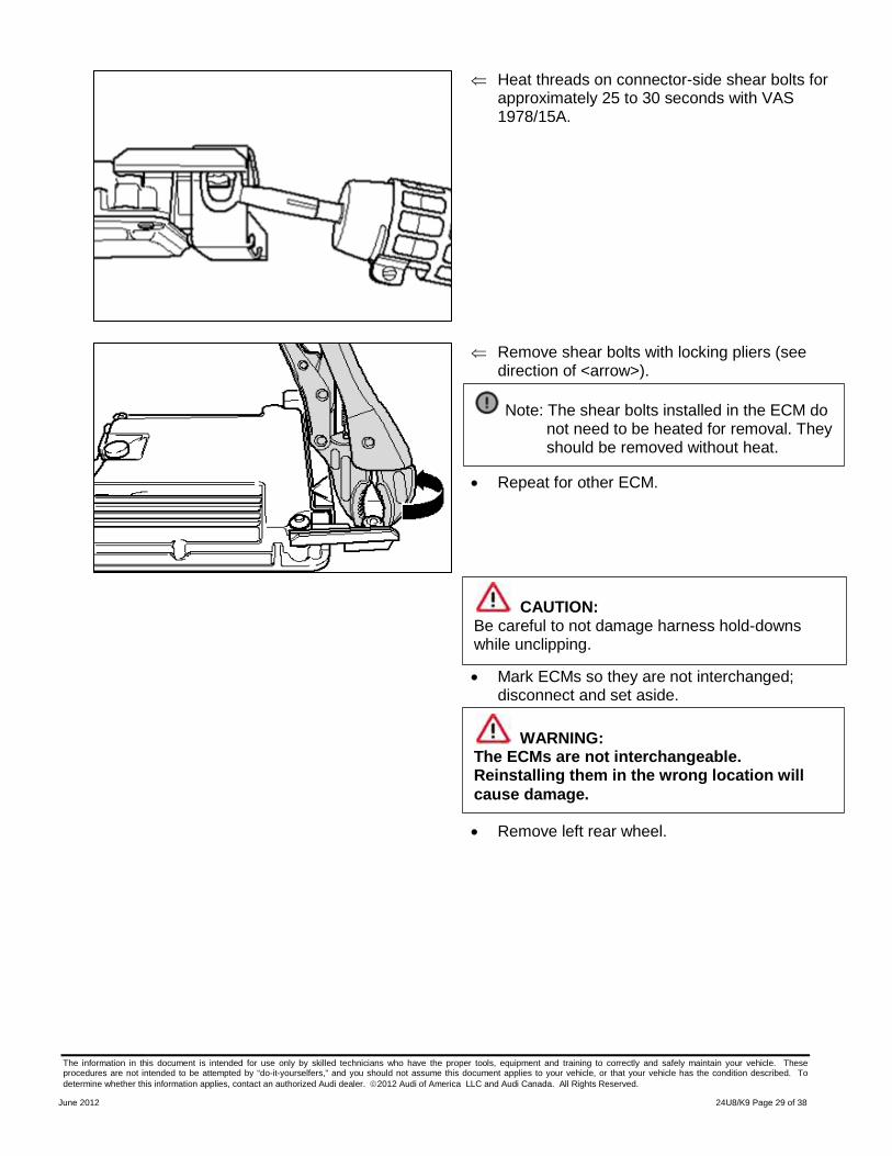
⇐ Heat threads on connector-side shear bolts for approximately 25 to 30 seconds with VAS 1978/15A.
⇐ Remove shear bolts with locking pliers (see
direction of <arrow>).
• Repeat for other ECM.
• Mark ECMs so they are not interchanged; disconnect and set aside.
• Remove left rear wheel.
Note: The shear bolts installed in the ECM do not need to be heated for removal. They should be removed without heat.
WARNING: The ECMs are not interchangeable. Reinstalling them in the wrong location will cause damage.
CAUTION: Be careful to not damage harness hold-downs while unclipping.
The information in this document is intended for use only by skilled technicians who have the proper tools, equipment and training to correctly and safely maintain your vehicle. These procedures are not intended to be attempted by “do-it-yourselfers,” and you should not assume this document applies to your vehicle, or that your vehicle has the condition described. To determine whether this information applies, contact an authorized Audi dealer. 2012 Audi of America LLC and Audi Canada. All Rights Reserved.
June 2012 24U8/K9 Page 30 of 38
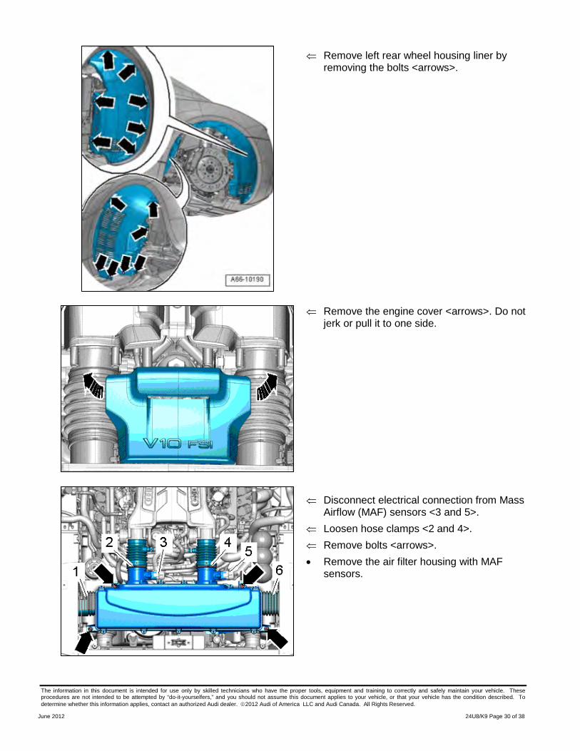
⇐ Remove left rear wheel housing liner by removing the bolts <arrows>.
⇐ Remove the engine cover <arrows>. Do not
jerk or pull it to one side.
⇐ Disconnect electrical connection from Mass
Airflow (MAF) sensors <3 and 5>. ⇐ Loosen hose clamps <2 and 4>. ⇐ Remove bolts <arrows>. • Remove the air filter housing with MAF
sensors.
The information in this document is intended for use only by skilled technicians who have the proper tools, equipment and training to correctly and safely maintain your vehicle. These procedures are not intended to be attempted by “do-it-yourselfers,” and you should not assume this document applies to your vehicle, or that your vehicle has the condition described. To determine whether this information applies, contact an authorized Audi dealer. 2012 Audi of America LLC and Audi Canada. All Rights Reserved.
June 2012 24U8/K9 Page 31 of 38
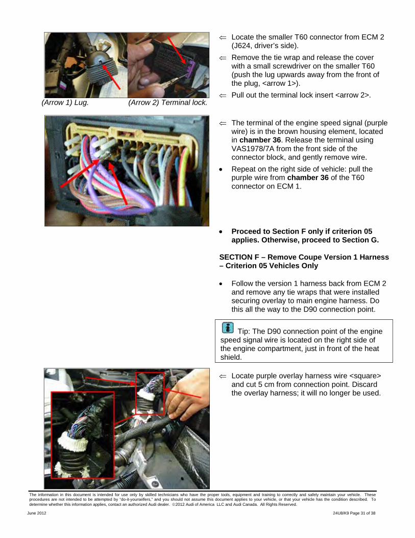
(Arrow 1) Lug. (Arrow 2) Terminal lock.
⇐ Locate the smaller T60 connector from ECM 2 (J624, driver’s side).
⇐ Remove the tie wrap and release the cover with a small screwdriver on the smaller T60 (push the lug upwards away from the front of the plug, <arrow 1>).
⇐ Pull out the terminal lock insert <arrow 2>.
⇐ The terminal of the engine speed signal (purple wire) is in the brown housing element, located in chamber 36. Release the terminal using VAS1978/7A from the front side of the connector block, and gently remove wire.
• Repeat on the right side of vehicle: pull the purple wire from chamber 36 of the T60 connector on ECM 1.
• Proceed to Section F only if criterion 05 applies. Otherwise, proceed to Section G.
SECTION F – Remove Coupe Version 1 Harness – Criterion 05 Vehicles Only
• Follow the version 1 harness back from ECM 2 and remove any tie wraps that were installed securing overlay to main engine harness. Do this all the way to the D90 connection point.
⇐ Locate purple overlay harness wire <square> and cut 5 cm from connection point. Discard the overlay harness; it will no longer be used.
Tip: The D90 connection point of the engine speed signal wire is located on the right side of the engine compartment, just in front of the heat shield.
The information in this document is intended for use only by skilled technicians who have the proper tools, equipment and training to correctly and safely maintain your vehicle. These procedures are not intended to be attempted by “do-it-yourselfers,” and you should not assume this document applies to your vehicle, or that your vehicle has the condition described. To determine whether this information applies, contact an authorized Audi dealer. 2012 Audi of America LLC and Audi Canada. All Rights Reserved.
June 2012 24U8/K9 Page 32 of 38
• Apply shrink tubing to remaining wire from the D90 connection. Shrink tubing with UT-100SI Ultratorch (or equivalent) and pinch the end of the tubing closed. Tape wire back in direction of the harness.
• Proceed to section G.
SECTION G: Installing Version 2 Harness on Coupe
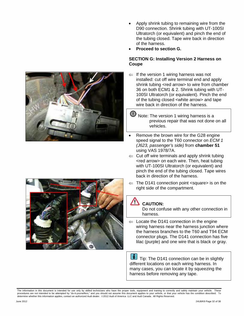
⇐ If the version 1 wiring harness was not installed: cut off wire terminal end and apply shrink tubing <red arrow> to wire from chamber 36 on both ECM1 & 2. Shrink tubing with UT-100SI Ultratorch (or equivalent). Pinch the end of the tubing closed <white arrow> and tape wire back in direction of the harness.
• Remove the brown wire for the G28 engine
speed signal to the T60 connector on ECM 1 (J623, passenger’s side) from chamber 51 using VAS 1978/7A.
⇐ Cut off wire terminals and apply shrink tubing <red arrow> on each wire. Then, heat tubing with UT-100SI Ultratorch (or equivalent) and pinch the end of the tubing closed. Tape wires back in direction of the harness.
⇐ The D141 connection point <square> is on the right side of the compartment.
⇐ Locate the D141 connection in the engine
wiring harness near the harness junction where the harness branches to the T60 and T94 ECM connector plugs. The D141 connection has five lilac (purple) and one wire that is black or gray.
CAUTION: Do not confuse with any other connection in harness.
Tip: The D141 connection can be in slightly different locations on each wiring harness. In many cases, you can locate it by squeezing the harness before removing any tape.
Note: The version 1 wiring harness is a previous repair that was not done on all vehicles.
The information in this document is intended for use only by skilled technicians who have the proper tools, equipment and training to correctly and safely maintain your vehicle. These procedures are not intended to be attempted by “do-it-yourselfers,” and you should not assume this document applies to your vehicle, or that your vehicle has the condition described. To determine whether this information applies, contact an authorized Audi dealer. 2012 Audi of America LLC and Audi Canada. All Rights Reserved.
June 2012 24U8/K9 Page 33 of 38
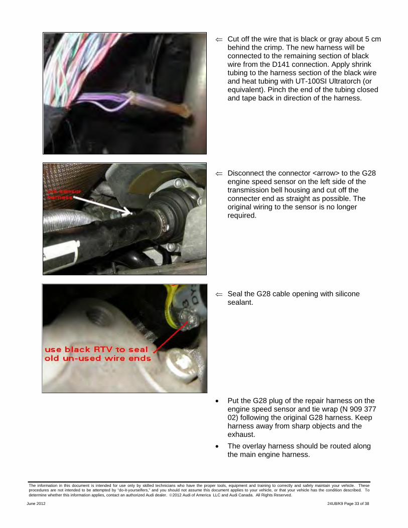
⇐ Cut off the wire that is black or gray about 5 cm behind the crimp. The new harness will be connected to the remaining section of black wire from the D141 connection. Apply shrink tubing to the harness section of the black wire and heat tubing with UT-100SI Ultratorch (or equivalent). Pinch the end of the tubing closed and tape back in direction of the harness.
⇐ Disconnect the connector <arrow> to the G28
engine speed sensor on the left side of the transmission bell housing and cut off the connecter end as straight as possible. The original wiring to the sensor is no longer required.
⇐ Seal the G28 cable opening with silicone
sealant.
• Put the G28 plug of the repair harness on the engine speed sensor and tie wrap (N 909 377 02) following the original G28 harness. Keep harness away from sharp objects and the exhaust.
• The overlay harness should be routed along the main engine harness.
The information in this document is intended for use only by skilled technicians who have the proper tools, equipment and training to correctly and safely maintain your vehicle. These procedures are not intended to be attempted by “do-it-yourselfers,” and you should not assume this document applies to your vehicle, or that your vehicle has the condition described. To determine whether this information applies, contact an authorized Audi dealer. 2012 Audi of America LLC and Audi Canada. All Rights Reserved.
June 2012 24U8/K9 Page 34 of 38
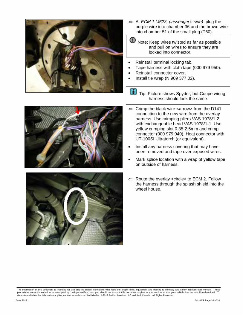
⇐ At ECM 1 (J623, passenger’s side): plug the purple wire into chamber 36 and the brown wire into chamber 51 of the small plug (T60).
• Reinstall terminal locking tab. • Tape harness with cloth tape (000 979 950). • Reinstall connector cover. • Install tie wrap (N 909 377 02).
⇐ Crimp the black wire <arrow> from the D141 connection to the new wire from the overlay harness. Use crimping pliers VAS 1978/1-2 with exchangeable head VAS 1978/1-1. Use yellow crimping slot 0.35-2.5mm and crimp connecter (000 979 940). Heat connector with UT-100SI Ultratorch (or equivalent).
• Install any harness covering that may have been removed and tape over exposed wires.
• Mark splice location with a wrap of yellow tape on outside of harness.
⇐ Route the overlay <circle> to ECM 2. Follow
the harness through the splash shield into the wheel house.
Note: Keep wires twisted as far as possible and pull on wires to ensure they are locked into connector.
Tip: Picture shows Spyder, but Coupe wiring harness should look the same.
The information in this document is intended for use only by skilled technicians who have the proper tools, equipment and training to correctly and safely maintain your vehicle. These procedures are not intended to be attempted by “do-it-yourselfers,” and you should not assume this document applies to your vehicle, or that your vehicle has the condition described. To determine whether this information applies, contact an authorized Audi dealer. 2012 Audi of America LLC and Audi Canada. All Rights Reserved.
June 2012 24U8/K9 Page 35 of 38
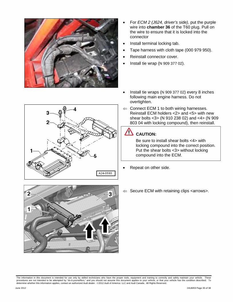
• For ECM 2 (J624, driver’s side), put the purple wire into chamber 36 of the T60 plug. Pull on the wire to ensure that it is locked into the connector
• Install terminal locking tab. • Tape harness with cloth tape (000 979 950). • Reinstall connector cover. • Install tie wrap (N 909 377 02).
• Install tie wraps (N 909 377 02) every 8 inches following main engine harness. Do not overtighten.
⇐ Connect ECM 1 to both wiring harnesses. Reinstall ECM holders <2> and <5> with new shear bolts <3> (N 910 238 02) and <4> (N 909 803 04 with locking compound), then reinstall.
• Repeat on other side.
⇐ Secure ECM with retaining clips <arrows>.
CAUTION: Be sure to install shear bolts <4> with locking compound into the correct position. Put the shear bolts <3> without locking compound into the ECM.
The information in this document is intended for use only by skilled technicians who have the proper tools, equipment and training to correctly and safely maintain your vehicle. These procedures are not intended to be attempted by “do-it-yourselfers,” and you should not assume this document applies to your vehicle, or that your vehicle has the condition described. To determine whether this information applies, contact an authorized Audi dealer. 2012 Audi of America LLC and Audi Canada. All Rights Reserved.
June 2012 24U8/K9 Page 36 of 38
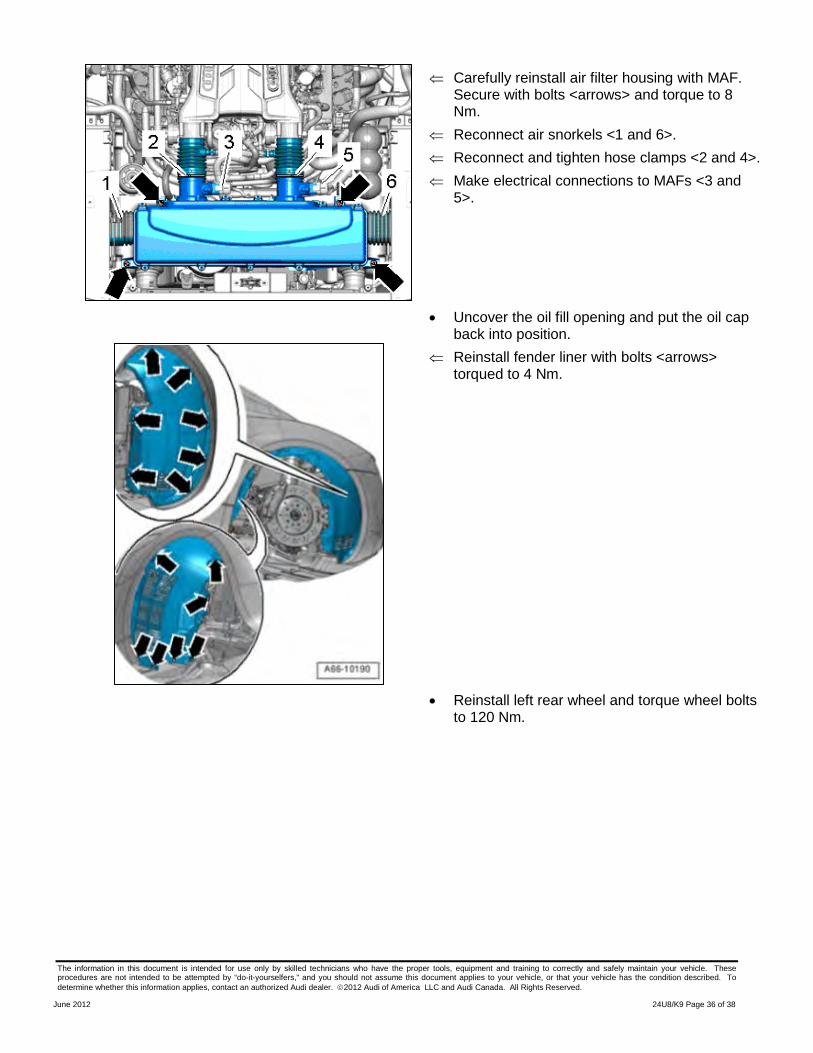
⇐ Carefully reinstall air filter housing with MAF. Secure with bolts <arrows> and torque to 8 Nm.
⇐ Reconnect air snorkels <1 and 6>. ⇐ Reconnect and tighten hose clamps <2 and 4>. ⇐ Make electrical connections to MAFs <3 and
5>.
• Uncover the oil fill opening and put the oil cap back into position.
⇐ Reinstall fender liner with bolts <arrows> torqued to 4 Nm.
• Reinstall left rear wheel and torque wheel bolts to 120 Nm.
The information in this document is intended for use only by skilled technicians who have the proper tools, equipment and training to correctly and safely maintain your vehicle. These procedures are not intended to be attempted by “do-it-yourselfers,” and you should not assume this document applies to your vehicle, or that your vehicle has the condition described. To determine whether this information applies, contact an authorized Audi dealer. 2012 Audi of America LLC and Audi Canada. All Rights Reserved.
June 2012 24U8/K9 Page 37 of 38
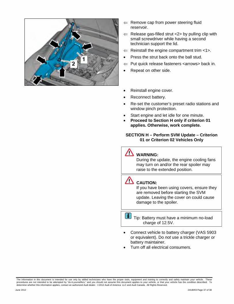
⇐ Remove cap from power steering fluid reservoir.
⇐ Release gas-filled strut <2> by pulling clip with small screwdriver while having a second technician support the lid.
⇐ Reinstall the engine compartment trim <1>. • Press the strut back onto the ball stud. ⇐ Put quick release fasteners <arrows> back in. • Repeat on other side.
• Reinstall engine cover. • Reconnect battery. • Re-set the customer’s preset radio stations and
window pinch protection. • Start engine and let idle for one minute.
• Proceed to Section H only if criterion 01 applies. Otherwise, work complete.
SECTION H – Perform SVM Update – Criterion
01 or Criterion 02 Vehicles Only
• Connect vehicle to battery charger (VAS 5903 or equivalent). Do not use a trickle charger or battery maintainer.
• Turn off all electrical consumers.
WARNING: During the update, the engine cooling fans may turn on and/or the rear spoiler may raise to the extended position.
CAUTION: If you have been using covers, ensure they are removed before starting the SVM update. Leaving the cover on could cause damage to the spoiler.
Tip: Battery must have a minimum no-load charge of 12.5V.
The information in this document is intended for use only by skilled technicians who have the proper tools, equipment and training to correctly and safely maintain your vehicle. These procedures are not intended to be attempted by “do-it-yourselfers,” and you should not assume this document applies to your vehicle, or that your vehicle has the condition described. To determine whether this information applies, contact an authorized Audi dealer. 2012 Audi of America LLC and Audi Canada. All Rights Reserved.
June 2012 24U8/K9 Page 38 of 38
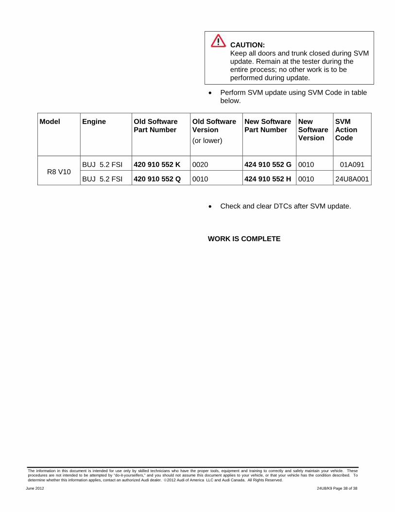
• Perform SVM update using SVM Code in table below.
Model Engine Old Software Part Number
Old Software Version (or lower)
New Software Part Number
New Software Version
SVM Action Code
R8 V10 BUJ 5.2 FSI 420 910 552 K 0020 424 910 552 G 0010 01A091
BUJ 5.2 FSI 420 910 552 Q 0010 424 910 552 H 0010 24U8A001 • Check and clear DTCs after SVM update. WORK IS COMPLETE
CAUTION: Keep all doors and trunk closed during SVM update. Remain at the tester during the entire process; no other work is to be performed during update.