Audi A8 Fitting Locations No. 802 / 1 - syntag · Audi A8 Fitting Locations No. 802 / 1 Edition...
42
Audi A8 Fitting Locations No. 802 / 1 Edition 04.2010 Fuses Overview of fuses 1 - Fuses (SB) on fuse holder, left dash panel Location → chapter Position of fuses, left-hand drive → chapter Position of fuses, right- hand drive → chapter 2 - Relay and fuse holder (S), in electronics box, in plenum chamber Position of fuses, left-hand drive → chapter Position of fuses, right- hand drive → chapter 3 - Relay and fuse holder (S), behind left dash panel Position of fuses, left-hand drive → chapter Position of fuses, right- hand drive → chapter 4 - Fuses (SC) on fuse holder, right dash panel Location → chapter Position of fuses, left-hand drive → chapter Position of fuses, right- hand drive → chapter Page 1 of 42 WI-XML 13.06.2013 file://C:\ElsaWin\docs\slp\A\en-GB\A00510200802.htm
Transcript of Audi A8 Fitting Locations No. 802 / 1 - syntag · Audi A8 Fitting Locations No. 802 / 1 Edition...

Audi A8 Fitting Locations No. 802 / 1Edition 04.2010
Fuses
Overview of fuses
1 - Fuses (SB) on fuse holder, left dash panel
Location → chapter
Position of fuses, left-hand drive → chapter
Position of fuses, right-hand drive → chapter
2 - Relay and fuse holder (S), in electronics box, in plenum chamber
Position of fuses, left-hand drive → chapter
Position of fuses, right-hand drive → chapter
3 - Relay and fuse holder (S), behind left dash panel
Position of fuses, left-hand drive → chapter
Position of fuses, right-hand drive → chapter
4 - Fuses (SC) on fuse holder, right dash panel
Location → chapter
Position of fuses, left-hand drive → chapter
Position of fuses, right-hand drive → chapter
Page 1 of 42WI-XML
13.06.2013file://C:\ElsaWin\docs\slp\A\en-GB\A00510200802.htm

Audi A8 Fitting Locations No. 802 / 2
5 - Fuses (S) on main fuse carrier, right A-pillar
Position of fuses → chapter
6 - Relay and fuse holder (S) in front right footwell
Position of fuses, left-hand drive → chapter
Position of fuses, right-hand drive → chapter
7 - Relay and fuse holder right in luggage compartment
Position of fuses → chapter
8 - Relay and fuse holder right in luggage compartment, fuses
Position of fuses → chapter
9 - Relay and fuse holder (SF) right in luggage compartment, fuses
Position of fuses, up to model year 2003 → chapter
Position of fuses, from model year 2004 → chapter
Position of fuses, right-hand drive → chapter
10 - Fuses (SD) on fuse holder, left in luggage compartment
Position of fuses, up to model year 2003 → chapter
Position of fuses, from model year 2004 → chapter
Position of fuses, right-hand drive → chapter
Page 2 of 42WI-XML
13.06.2013file://C:\ElsaWin\docs\slp\A\en-GB\A00510200802.htm
Audi A8 Fitting Locations No. 802 / 3
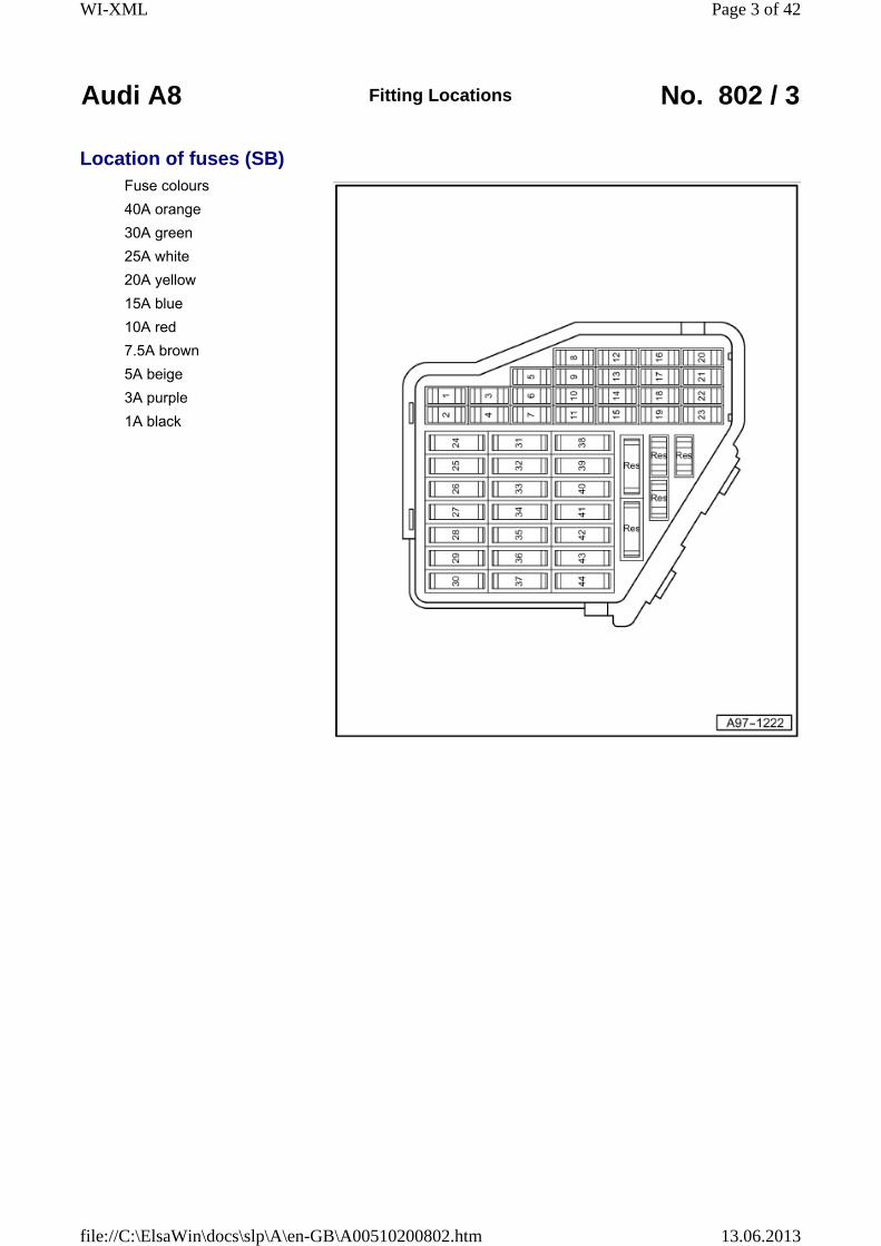
Location of fuses (SB)Fuse colours
40A orange
30A green
25A white
20A yellow
15A blue
10A red
7.5A brown
5A beige
3A purple
1A black
Page 3 of 42WI-XML
13.06.2013file://C:\ElsaWin\docs\slp\A\en-GB\A00510200802.htm
Audi A8 Fitting Locations No. 802 / 4
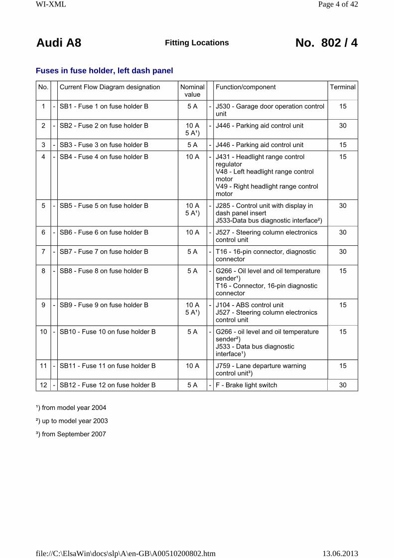
Fuses in fuse holder, left dash panel
No. Current Flow Diagram designation Nominal value
Function/component Terminal
1 - SB1 - Fuse 1 on fuse holder B 5 A - J530 - Garage door operation control unit
15
2 - SB2 - Fuse 2 on fuse holder B 10 A 5 A¹)
- J446 - Parking aid control unit 30
3 - SB3 - Fuse 3 on fuse holder B 5 A - J446 - Parking aid control unit 15
4 - SB4 - Fuse 4 on fuse holder B 10 A - J431 - Headlight range control regulator V48 - Left headlight range control motor V49 - Right headlight range control motor
15
5 - SB5 - Fuse 5 on fuse holder B 10 A 5 A¹)
- J285 - Control unit with display in dash panel insert J533-Data bus diagnostic interface²)
30
6 - SB6 - Fuse 6 on fuse holder B 10 A - J527 - Steering column electronics control unit
30
7 - SB7 - Fuse 7 on fuse holder B 5 A - T16 - 16-pin connector, diagnostic connector
30
8 - SB8 - Fuse 8 on fuse holder B 5 A - G266 - Oil level and oil temperature sender¹) T16 - Connector, 16-pin diagnostic connector
15
9 - SB9 - Fuse 9 on fuse holder B 10 A 5 A¹)
- J104 - ABS control unit J527 - Steering column electronics control unit
15
10 - SB10 - Fuse 10 on fuse holder B 5 A - G266 - oil level and oil temperature sender²) J533 - Data bus diagnostic interface¹)
15
11 - SB11 - Fuse 11 on fuse holder B 10 A J759 - Lane departure warning control unit³)
15
12 - SB12 - Fuse 12 on fuse holder B 5 A - F - Brake light switch 30
¹) from model year 2004
²) up to model year 2003
³) from September 2007
Page 4 of 42WI-XML
13.06.2013file://C:\ElsaWin\docs\slp\A\en-GB\A00510200802.htm

Audi A8 Fitting Locations No. 802 / 5
No. Current Flow Diagram designation Nominal value
Function/component Terminal
13 - SB13 - Fuse 13 on fuse holder B 10 A - J412 - Telephone operating electronics control unit J526 - Mobile telephone operating electronics control unit R36 - Telephone transmitter and receiver unit R115 - Chip card reader for telephone
30
5 A�) - R86 - Aerial amplifier for mobile telephone �) R126 - Telephone bracket�)
30
14 - SB14 - Fuse 14 on fuse holder B 5 A - J608 - Special vehicle control unit³) 30
15 - SB15 - Fuse 15 on fuse holder B 5 A - E408 - Entry and start authorisation button
30
16 - SB16 - Fuse 16 on fuse holder B 10 A - - Rear-Seat-Entertainment 15
17 - SB17 - Fuse 17 on fuse holder B 10 A 5 A¹)
- J428 - Adaptive cruise control unit Z47 - Sensor heater for adaptive cruise control system²)
15
18 - SB18 - Fuse 18 on fuse holder B 5 A - Z20 -Left washer jet heater element Z21 -Right washer jet heater element
75
19 - SB19 - Fuse 19 on fuse holder B 15 A 10 A³)
- J608 - Special vehicle control unit³) J711 - Washer fluid heater relay²)
30 75
20 - SB20 - Fuse 20 on fuse holder B 5 A - J502 - Tyre pressure monitor control unit 30
21 - SB21 - Fuse 21 on fuse holder B 5 A - J608 - Special vehicle control unit³) 15
22 - SB22 - Fuse 22 on fuse holder B 5 A - F47 - Brake pedal switch 87
23 - SB23 - Fuse 23 on fuse holder B 5 A - - Card system Italy (Telepass) - Preparation for mobile telephone³)
30
24 - SB24 - Fuse 24 on fuse holder B 15 A - H2 -Treble tone horn H7 - Bass tone horn J4 -Dual tone horn relay
30
¹) from model year 2004
²) up to model year 2004
³) from model year 2006
�) from September 2008
Page 5 of 42WI-XML
13.06.2013file://C:\ElsaWin\docs\slp\A\en-GB\A00510200802.htm

Audi A8 Fitting Locations No. 802 / 6
No. Current Flow Diagram designation Nominal value
Function/component Terminal
25 - SB25 - Fuse 25 on fuse holder B 40 A - J400 - Wiper motor control unit 30
26 - SB26 - Fuse 26 on fuse holder B 15 A³) 30 A²)
- J608 - Special vehicle control unit³) U18 - 12 V socket 2²) U19 - 12 V socket 3²)
30
27 - SB27 - Fuse 27 on fuse holder B 25 A - J104 - ABS control unit 30
28 - Vacant
29 - SB29 - Fuse 29 on fuse holder B 1 A - - Switch illumination 58s
30 - Vacant
31 - SB31 - Fuse 31 on fuse holder B 30 A - J519 - Onboard power supply control unit
30
32 - SB32 - Fuse 32 on fuse holder B 5 A�) - J685 - Display unit for front information display and operating unit control unit �)
30
33 - SB33 - Fuse 33 on fuse holder B 25 A - Z42-Rear left footwell heater element 75
34 - Vacant
35 - Vacant
36 - SB36 - Fuse 36 on fuse holder B 5 A J769 - Lane change assist control unit�)
15
37 - SB37 - Fuse 37 on fuse holder B 15 A - J698 - Refrigerator box³) 15
38 - SB38 - Fuse 38 on fuse holder B 30 A - J519 - Onboard power supply control unit
30
39 - SB39 - Fuse 39 on fuse holder B 15 A 7.5 A¹)
- J386 - Driver door control unit 30
¹) from model year 2004
²) up to model year 2004
³) from model year 2006
�) from September 2007
�) from September 2008
Page 6 of 42WI-XML
13.06.2013file://C:\ElsaWin\docs\slp\A\en-GB\A00510200802.htm

Audi A8 Fitting Locations No. 802 / 7
No. Current Flow Diagram designation Nominal value
Function/component Terminal
40 - SB40 - Fuse 40 on fuse holder B 25 A - J519 - Onboard supply control unit V123 - steering column vertical adjustment motor V124 - Steering column axial adjustment motor
30
41 - SB41 - Fuse 41 on fuse holder B 15 A 7.5 A¹)
- J388 - Rear left door control unit 30
42 - SB42 - Fuse 42 on fuse holder B 25 A - J518 - Entry and start authorisation control unit
30
43 - SB43 - Fuse 43 on fuse holder B 10 A - Left headlight with cornering lights²) 15
44 - SB44 - Fuse 44 on fuse holder B 10 A - - Right headlight with cornering lights²)
15
¹) from model year 2004
²) from model year 2006
Page 7 of 42WI-XML
13.06.2013file://C:\ElsaWin\docs\slp\A\en-GB\A00510200802.htm
Audi A8 Fitting Locations No. 802 / 8
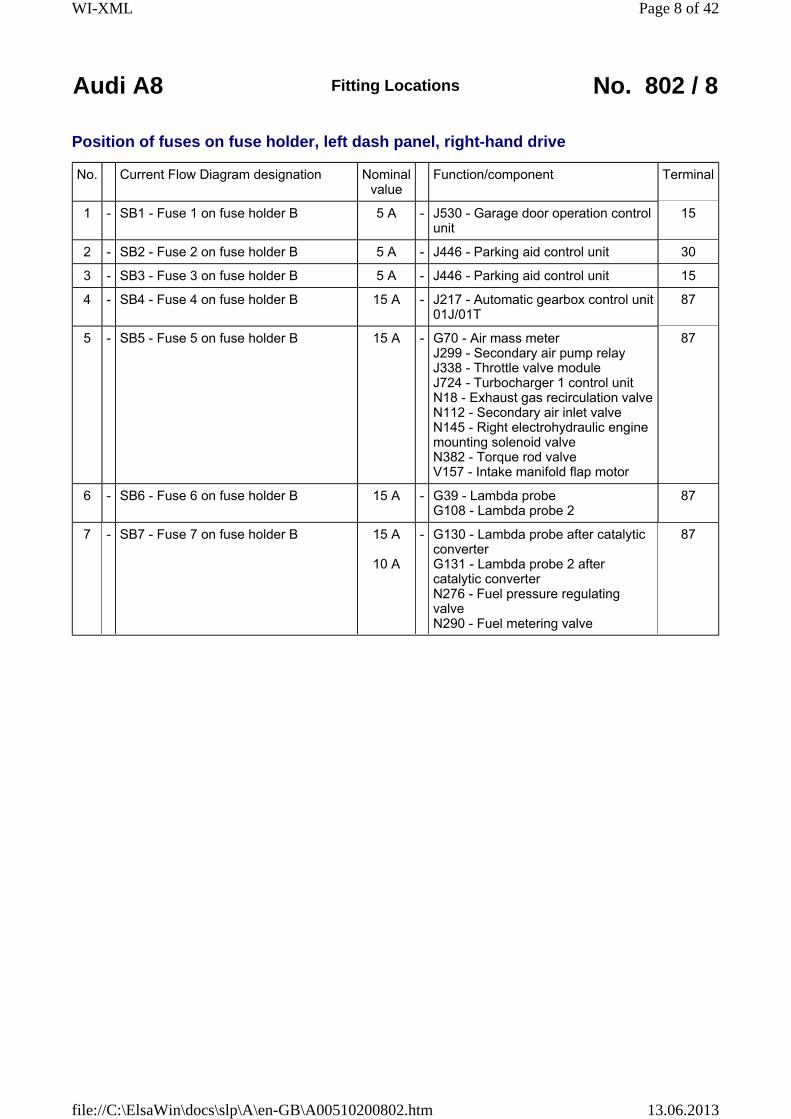
Position of fuses on fuse holder, left dash panel, right-hand drive
No. Current Flow Diagram designation Nominal value
Function/component Terminal
1 - SB1 - Fuse 1 on fuse holder B 5 A - J530 - Garage door operation control unit
15
2 - SB2 - Fuse 2 on fuse holder B 5 A - J446 - Parking aid control unit 30
3 - SB3 - Fuse 3 on fuse holder B 5 A - J446 - Parking aid control unit 15
4 - SB4 - Fuse 4 on fuse holder B 15 A - J217 - Automatic gearbox control unit 01J/01T
87
5 - SB5 - Fuse 5 on fuse holder B 15 A - G70 - Air mass meter J299 - Secondary air pump relay J338 - Throttle valve module J724 - Turbocharger 1 control unit N18 - Exhaust gas recirculation valve N112 - Secondary air inlet valve N145 - Right electrohydraulic engine mounting solenoid valve N382 - Torque rod valve V157 - Intake manifold flap motor
87
6 - SB6 - Fuse 6 on fuse holder B 15 A - G39 - Lambda probe G108 - Lambda probe 2
87
7 - SB7 - Fuse 7 on fuse holder B 15 A
10 A
- G130 - Lambda probe after catalytic converter G131 - Lambda probe 2 after catalytic converter N276 - Fuel pressure regulating valve N290 - Fuel metering valve
87
Page 8 of 42WI-XML
13.06.2013file://C:\ElsaWin\docs\slp\A\en-GB\A00510200802.htm

Audi A8 Fitting Locations No. 802 / 9
No. Current Flow Diagram designation Nominal value
Function/component Terminal
8 - SB8 - Fuse 8 on fuse holder B 10 A - J544 - Throttle valve module 2 J725 - Turbocharger 2 control unit N144 - Left electrohydraulic engine mounting solenoid valve N205 - Inlet camshaft control valve 1 N208 - Inlet camshaft control valve N213 - Exhaust gas recirculation valve 2 N321 - Exhaust flap 1 valve N382 - Torque rod valve V51 - Continued coolant circulation pump V275 - Intake manifold flap 2 motor
87
9 - SB9 - Fuse 9 on fuse holder B 5 A - J104 - ABS control unit J527 - Steering column electronics control unit
15
10 - SB10 - Fuse 10 on fuse holder B 10 A - J197 - Adaptive suspension control unit
15
11 - SB11 - Fuse 11 on fuse holder B 10 A - J759 - Lane departure warning control unit
15
12 - SB12 - Fuse 12 on fuse holder B 5 A
7.5 A¹)
- J523 - Front information display and operating unit control unit J794 - Control unit for information electronics 1¹)
30
13 - SB13 - Fuse 13 on fuse holder B 10 A - J412 - Telephone operating electronics control unit J526 - Mobile telephone operating electronics control unit R36 - Telephone transmitter and receiver unit R115 - Chip card reader for telephone - Preparation for mobile telephone
30
5 A¹) - R86 - Aerial amplifier for mobile telephone¹) R126 - Telephone bracket¹)
30
¹) from September 2008
Page 9 of 42WI-XML
13.06.2013file://C:\ElsaWin\docs\slp\A\en-GB\A00510200802.htm
Audi A8 Fitting Locations No. 802 / 10
No. Current Flow Diagram designation Nominal value
Function/component Terminal
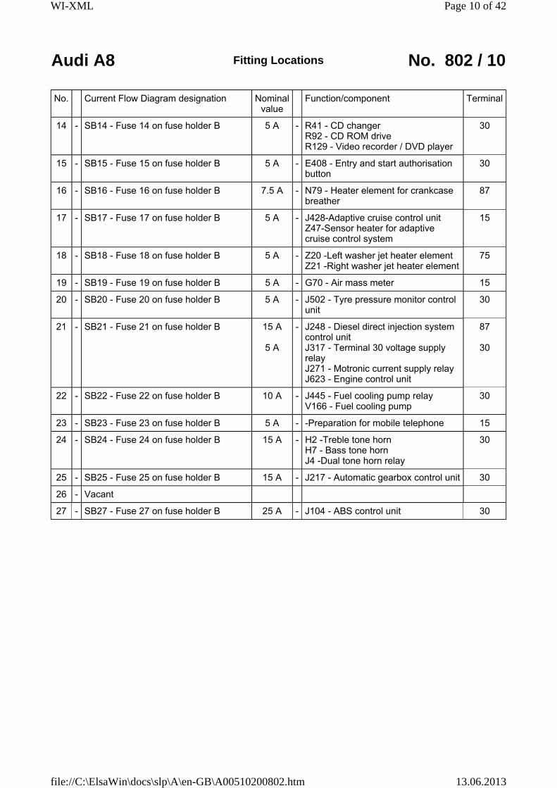
14 - SB14 - Fuse 14 on fuse holder B 5 A - R41 - CD changer R92 - CD ROM drive R129 - Video recorder / DVD player
30
15 - SB15 - Fuse 15 on fuse holder B 5 A - E408 - Entry and start authorisation button
30
16 - SB16 - Fuse 16 on fuse holder B 7.5 A - N79 - Heater element for crankcase breather
87
17 - SB17 - Fuse 17 on fuse holder B 5 A - J428-Adaptive cruise control unit Z47-Sensor heater for adaptive cruise control system
15
18 - SB18 - Fuse 18 on fuse holder B 5 A - Z20 -Left washer jet heater element Z21 -Right washer jet heater element
75
19 - SB19 - Fuse 19 on fuse holder B 5 A - G70 - Air mass meter 15
20 - SB20 - Fuse 20 on fuse holder B 5 A - J502 - Tyre pressure monitor control unit
30
21 - SB21 - Fuse 21 on fuse holder B 15 A
5 A
- J248 - Diesel direct injection system control unit J317 - Terminal 30 voltage supply relay J271 - Motronic current supply relay J623 - Engine control unit
87
30
22 - SB22 - Fuse 22 on fuse holder B 10 A - J445 - Fuel cooling pump relay V166 - Fuel cooling pump
30
23 - SB23 - Fuse 23 on fuse holder B 5 A - -Preparation for mobile telephone 15
24 - SB24 - Fuse 24 on fuse holder B 15 A - H2 -Treble tone horn H7 - Bass tone horn J4 -Dual tone horn relay
30
25 - SB25 - Fuse 25 on fuse holder B 15 A - J217 - Automatic gearbox control unit 30
26 - Vacant
27 - SB27 - Fuse 27 on fuse holder B 25 A - J104 - ABS control unit 30
Page 10 of 42WI-XML
13.06.2013file://C:\ElsaWin\docs\slp\A\en-GB\A00510200802.htm
Audi A8 Fitting Locations No. 802 / 11
No. Current Flow Diagram designation Nominal value
Function/component Terminal
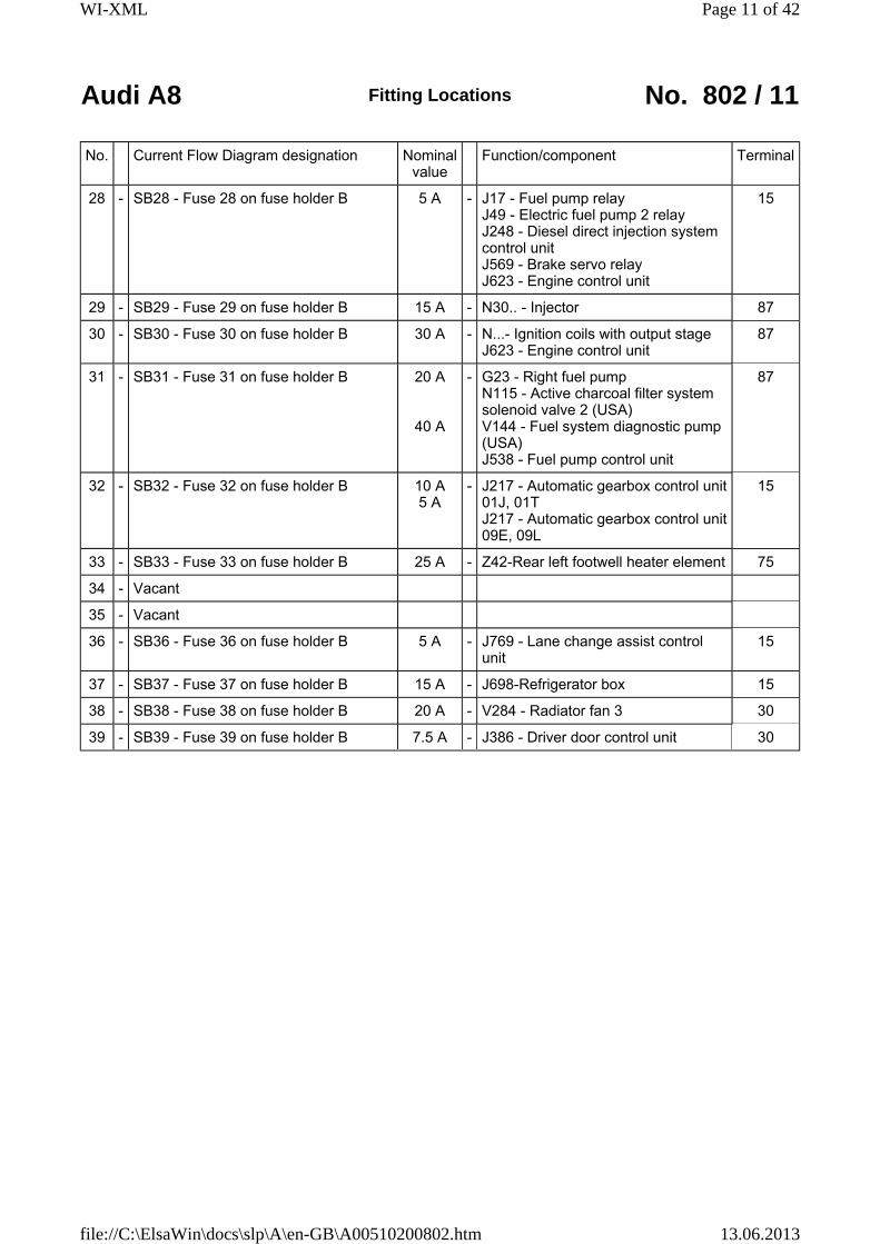
28 - SB28 - Fuse 28 on fuse holder B 5 A - J17 - Fuel pump relay J49 - Electric fuel pump 2 relay J248 - Diesel direct injection system control unit J569 - Brake servo relay J623 - Engine control unit
15
29 - SB29 - Fuse 29 on fuse holder B 15 A - N30.. - Injector 87
30 - SB30 - Fuse 30 on fuse holder B 30 A - N...- Ignition coils with output stage J623 - Engine control unit
87
31 - SB31 - Fuse 31 on fuse holder B 20 A
40 A
- G23 - Right fuel pump N115 - Active charcoal filter system solenoid valve 2 (USA) V144 - Fuel system diagnostic pump (USA) J538 - Fuel pump control unit
87
32 - SB32 - Fuse 32 on fuse holder B 10 A 5 A
- J217 - Automatic gearbox control unit 01J, 01T J217 - Automatic gearbox control unit 09E, 09L
15
33 - SB33 - Fuse 33 on fuse holder B 25 A - Z42-Rear left footwell heater element 75
34 - Vacant
35 - Vacant
36 - SB36 - Fuse 36 on fuse holder B 5 A - J769 - Lane change assist control unit
15
37 - SB37 - Fuse 37 on fuse holder B 15 A - J698-Refrigerator box 15
38 - SB38 - Fuse 38 on fuse holder B 20 A - V284 - Radiator fan 3 30
39 - SB39 - Fuse 39 on fuse holder B 7.5 A - J386 - Driver door control unit 30
Page 11 of 42WI-XML
13.06.2013file://C:\ElsaWin\docs\slp\A\en-GB\A00510200802.htm

Audi A8 Fitting Locations No. 802 / 12
No. Current Flow Diagram designation Nominal value
Function/component Terminal
40 - SB40 - Fuse 40 on fuse holder B 15 A - J569-Brake servo relay V192-Vacuum pump for brakes
30
41 - SB41 - Fuse 41 on fuse holder B 7.5 A - J388 - Rear left door control unit 30
42 - SB42 - Fuse 42 on fuse holder B 25 A - J518 - Entry and start authorisation control unit
30
43 - SB43 - Fuse 43 on fuse holder B 10 A - - Left headlight with cornering lights 15
44 - SB44 - Fuse 44 on fuse holder B 10 A - - Right headlight with cornering lights 15
Page 12 of 42WI-XML
13.06.2013file://C:\ElsaWin\docs\slp\A\en-GB\A00510200802.htm

Audi A8 Fitting Locations No. 802 / 13
Location of fuses (SC)Fuse colours
40A orange
30A green
25A white
20A yellow
15A blue
10A red
7.5A brown
5A beige
3A purple
1A black
Page 13 of 42WI-XML
13.06.2013file://C:\ElsaWin\docs\slp\A\en-GB\A00510200802.htm
Audi A8 Fitting Locations No. 802 / 14
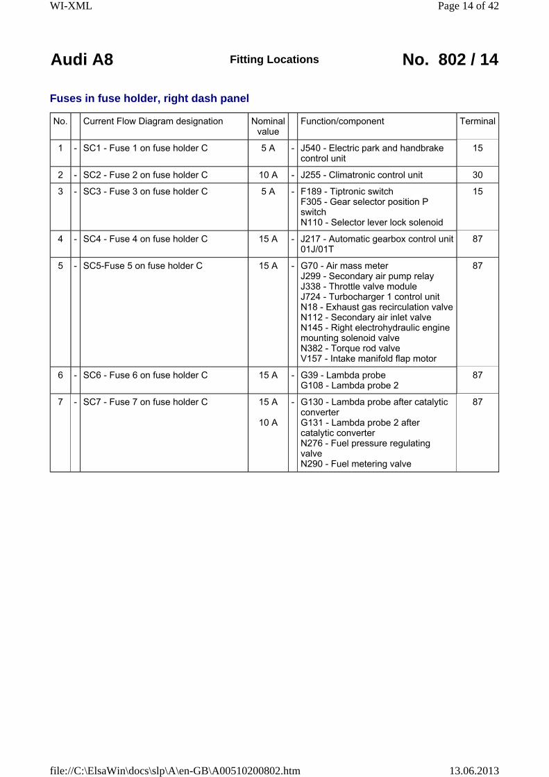
Fuses in fuse holder, right dash panel
No. Current Flow Diagram designation Nominal value
Function/component Terminal
1 - SC1 - Fuse 1 on fuse holder C 5 A - J540 - Electric park and handbrake control unit
15
2 - SC2 - Fuse 2 on fuse holder C 10 A - J255 - Climatronic control unit 30
3 - SC3 - Fuse 3 on fuse holder C 5 A - F189 - Tiptronic switch F305 - Gear selector position P switch N110 - Selector lever lock solenoid
15
4 - SC4 - Fuse 4 on fuse holder C 15 A - J217 - Automatic gearbox control unit 01J/01T
87
5 - SC5-Fuse 5 on fuse holder C 15 A - G70 - Air mass meter J299 - Secondary air pump relay J338 - Throttle valve module J724 - Turbocharger 1 control unit N18 - Exhaust gas recirculation valve N112 - Secondary air inlet valve N145 - Right electrohydraulic engine mounting solenoid valve N382 - Torque rod valve V157 - Intake manifold flap motor
87
6 - SC6 - Fuse 6 on fuse holder C 15 A - G39 - Lambda probe G108 - Lambda probe 2
87
7 - SC7 - Fuse 7 on fuse holder C 15 A
10 A
- G130 - Lambda probe after catalytic converter G131 - Lambda probe 2 after catalytic converter N276 - Fuel pressure regulating valve N290 - Fuel metering valve
87
Page 14 of 42WI-XML
13.06.2013file://C:\ElsaWin\docs\slp\A\en-GB\A00510200802.htm
Audi A8 Fitting Locations No. 802 / 15
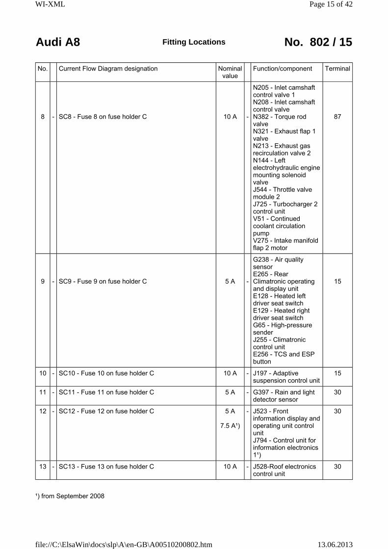
No. Current Flow Diagram designation Nominal value
Function/component Terminal
8
-
SC8 - Fuse 8 on fuse holder C
10 A -
N205 - Inlet camshaft control valve 1 N208 - Inlet camshaft control valve N382 - Torque rod valve N321 - Exhaust flap 1 valve N213 - Exhaust gas recirculation valve 2 N144 - Left electrohydraulic engine mounting solenoid valve J544 - Throttle valve module 2 J725 - Turbocharger 2 control unit V51 - Continued coolant circulation pump V275 - Intake manifold flap 2 motor
87
9
-
SC9 - Fuse 9 on fuse holder C
5 A -
G238 - Air quality sensor E265 - Rear Climatronic operating and display unit E128 - Heated left driver seat switch E129 - Heated right driver seat switch G65 - High-pressure sender J255 - Climatronic control unit E256 - TCS and ESP button
15
10 - SC10 - Fuse 10 on fuse holder C 10 A - J197 - Adaptive suspension control unit
15
11 - SC11 - Fuse 11 on fuse holder C 5 A - G397 - Rain and light detector sensor
30
12 - SC12 - Fuse 12 on fuse holder C 5 A
7.5 A¹)
- J523 - Front information display and operating unit control unit J794 - Control unit for information electronics 1¹)
30
13 - SC13 - Fuse 13 on fuse holder C 10 A - J528-Roof electronics control unit
30
¹) from September 2008
Page 15 of 42WI-XML
13.06.2013file://C:\ElsaWin\docs\slp\A\en-GB\A00510200802.htm
Audi A8 Fitting Locations No. 802 / 16
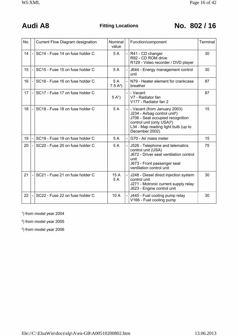
No. Current Flow Diagram designation Nominal value
Function/component Terminal
14 - SC14 - Fuse 14 on fuse holder C 5 A - R41 - CD changer R92 - CD ROM drive R129 - Video recorder / DVD player
30
15 - SC15 - Fuse 15 on fuse holder C 5 A - J644 - Energy management control unit
30
16 - SC16 - Fuse 16 on fuse holder C 5 A 7.5 A³)
- N79 - Heater element for crankcase breather
87
17 - SC17 - Fuse 17 on fuse holder C 5 A¹)
- - Vacant V7 - Radiator fan V177 - Radiator fan 2
87
18 - SC18 - Fuse 18 on fuse holder C 5 A - - Vacant (from January 2003) J234 - Airbag control unit²) J706 - Seat occupied recognition control unit (only USA)²) L34 - Map reading light bulb (up to December 2002)
15
19 - SC19 - Fuse 19 on fuse holder C 5 A - G70 - Air mass meter 15
20 - SC20 - Fuse 20 on fuse holder C 5 A - J526 - Telephone and telematics control unit (USA) J672 - Driver seat ventilation control unit J673 - Front passenger seat ventilation control unit
75
21 - SC21 - Fuse 21 on fuse holder C 15 A 5 A
- J248 - Diesel direct injection system control unit J271 - Motronic current supply relay J623 - Engine control unit
30
22 - SC22 - Fuse 22 on fuse holder C 10 A - J445 - Fuel cooling pump relay V166 - Fuel cooling pump
30
¹) from model year 2004
²) from model year 2005
³) from model year 2006
Page 16 of 42WI-XML
13.06.2013file://C:\ElsaWin\docs\slp\A\en-GB\A00510200802.htm

Audi A8 Fitting Locations No. 802 / 17
No. Current Flow Diagram designation Nominal value
Function/component Terminal
23 - SC23 - Fuse 23 on fuse holder C 5 A - F234 - Parking brake pressure switch 30
24 - SC24 - Fuse 24 on fuse holder C 20 A 10 A¹)
- J520 - Onboard supply control unit 2 30
25 - SC25 - Fuse 25 on fuse holder C 15 A - J217 - Automatic gearbox control unit 30
26 - SC26 - Fuse 26 on fuse holder C 15 A 10 A¹)
- E265-Rear Climatronic operating and display unit J255-Climatronic control unit
30
27 - SC27 - Fuse 27 on fuse holder C 20 A - J245 - Sliding sunroof adjustment control unit
30
28 - SC28 - Fuse 28 on fuse holder C 15 A 5 A¹)
- J17 - Fuel pump relay J49 - Electric fuel pump 2 relay J248 - Diesel direct injection system control unit J569 - Brake servo relay J623 - Engine control unit
15
29 - SC29 - Fuse 29 on fuse holder C 20 A 15 A¹)
- N30.. - Injector 87
30 - SC30 - Fuse 30 on fuse holder C 30 A - N...- Ignition coils with output stage J623 - Engine control unit
87
31 - SC31 - Fuse 31 on fuse holder C 20 A
40 A
- G23 - Right fuel pump N115 - Active charcoal filter system solenoid valve 2 (USA) V144 - Fuel system diagnostic pump (USA) J538 - Fuel pump control unit
87
32 - SC32 - Fuse 32 on fuse holder C 15 A 10 A¹) 5 A²)
- J217 - Automatic gearbox control unit 01J, 01T J217 - Automatic gearbox control unit 09E, 09L
15
¹) from model year 2004
²) from model year 2006
Page 17 of 42WI-XML
13.06.2013file://C:\ElsaWin\docs\slp\A\en-GB\A00510200802.htm
Audi A8 Fitting Locations No. 802 / 18
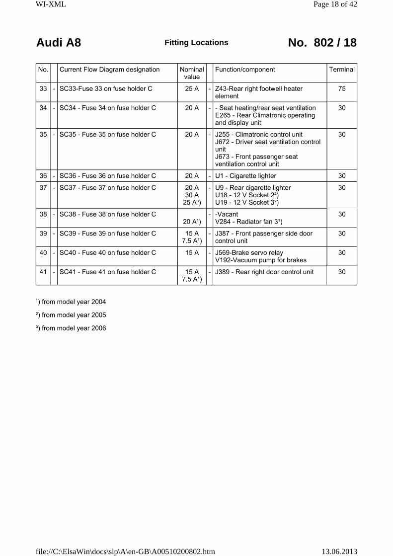
No. Current Flow Diagram designation Nominal value
Function/component Terminal
33 - SC33-Fuse 33 on fuse holder C 25 A - Z43-Rear right footwell heater element
75
34 - SC34 - Fuse 34 on fuse holder C 20 A - - Seat heating/rear seat ventilation E265 - Rear Climatronic operating and display unit
30
35 - SC35 - Fuse 35 on fuse holder C 20 A - J255 - Climatronic control unit J672 - Driver seat ventilation control unit J673 - Front passenger seat ventilation control unit
30
36 - SC36 - Fuse 36 on fuse holder C 20 A - U1 - Cigarette lighter 30
37 - SC37 - Fuse 37 on fuse holder C 20 A 30 A
25 A³)
- U9 - Rear cigarette lighter U18 - 12 V Socket 2²) U19 - 12 V Socket 3²)
30
38 - SC38 - Fuse 38 on fuse holder C 20 A¹)
- -Vacant V284 - Radiator fan 3¹)
30
39 - SC39 - Fuse 39 on fuse holder C 15 A 7.5 A¹)
- J387 - Front passenger side door control unit
30
40 - SC40 - Fuse 40 on fuse holder C 15 A - J569-Brake servo relay V192-Vacuum pump for brakes
30
41 - SC41 - Fuse 41 on fuse holder C 15 A 7.5 A¹)
- J389 - Rear right door control unit 30
¹) from model year 2004
²) from model year 2005
³) from model year 2006
Page 18 of 42WI-XML
13.06.2013file://C:\ElsaWin\docs\slp\A\en-GB\A00510200802.htm
Audi A8 Fitting Locations No. 802 / 19
No. Current Flow Diagram designation Nominal value
Function/component Terminal
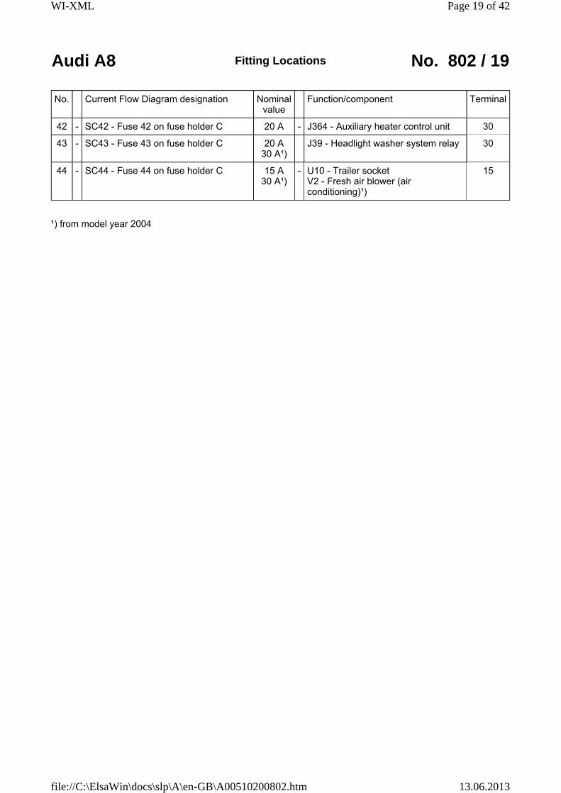
42 - SC42 - Fuse 42 on fuse holder C 20 A - J364 - Auxiliary heater control unit 30
43 - SC43 - Fuse 43 on fuse holder C 20 A 30 A¹)
J39 - Headlight washer system relay 30
44 - SC44 - Fuse 44 on fuse holder C 15 A 30 A¹)
- U10 - Trailer socket V2 - Fresh air blower (air conditioning)¹)
15
¹) from model year 2004
Page 19 of 42WI-XML
13.06.2013file://C:\ElsaWin\docs\slp\A\en-GB\A00510200802.htm

Audi A8 Fitting Locations No. 802 / 20
Position of fuses on fuse holder, right dash panel, right-hand drive
No. Current Flow Diagram designation Nominal value
Function/component Terminal
1 - SC1 - Fuse 1 on fuse holder C 5 A - J540 - Electric park and handbrake control unit
15
2 - SC2 - Fuse 2 on fuse holder C 10 A - J255 - Climatronic control unit 30
3 - SC3 - Fuse 3 on fuse holder C 5 A - F189 - Tiptronic switch F305 - Gear selector position P switch N110 - Selector lever lock solenoid
15
4 - SC4 - Fuse 4 on fuse holder C 10 A - J431 - Headlight range control regulator V48 - Left headlight range control motor V49 - Right headlight range control motor
15
5 - SC5-Fuse 5 on fuse holder C 5 A - J285-Control unit with display in dash panel insert J533-Data bus diagnostic interface
30
6 - SC6 - Fuse 6 on fuse holder C 10 A - J527 - Steering column electronics control unit
30
7 - SC7 - Fuse 7 on fuse holder C 5 A - T16 - 16-pin connector, diagnostic connector
30
8 - SC8 - Fuse 8 on fuse holder C 5 A - G266 - Oil level and oil temperature sender T16 - Connector, 16-pin diagnostic connector
15
9 - SC9 - Fuse 9 on fuse holder C 5 A - E128 - Heated rear left seat switch with regulator E129 - Heated rear right seat switch with regulator E256 - TCS and ESP button E265 - Rear Climatronic operating and display unit G65 - High-pressure sender G238 - Air quality sensor J255- Climatronic control unit
15
Page 20 of 42WI-XML
13.06.2013file://C:\ElsaWin\docs\slp\A\en-GB\A00510200802.htm
Audi A8 Fitting Locations No. 802 / 21
No. Current Flow Diagram designation Nominal value
Function/component Terminal
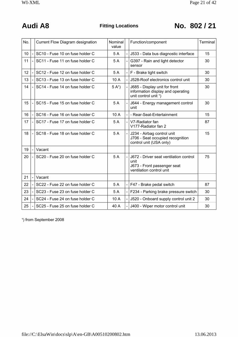
10 - SC10 - Fuse 10 on fuse holder C 5 A - J533 - Data bus diagnostic interface 15
11 - SC11 - Fuse 11 on fuse holder C 5 A - G397 - Rain and light detector sensor
30
12 - SC12 - Fuse 12 on fuse holder C 5 A - F - Brake light switch 30
13 - SC13 - Fuse 13 on fuse holder C 10 A - J528-Roof electronics control unit 30
14 - SC14 - Fuse 14 on fuse holder C 5 A¹) - J685 - Display unit for front information display and operating unit control unit ¹)
30
15 - SC15 - Fuse 15 on fuse holder C 5 A - J644 - Energy management control unit
30
16 - SC16 - Fuse 16 on fuse holder C 10 A - - Rear-Seat-Entertainment 15
17 - SC17 - Fuse 17 on fuse holder C 5 A - V7-Radiator fan V177-Radiator fan 2
87
18 - SC18 - Fuse 18 on fuse holder C 5 A - J234 - Airbag control unit J706 - Seat occupied recognition control unit (USA only)
15
19 - Vacant
20 - SC20 - Fuse 20 on fuse holder C 5 A - J672 - Driver seat ventilation control unit J673 - Front passenger seat ventilation control unit
75
21 - Vacant
22 - SC22 - Fuse 22 on fuse holder C 5 A - F47 - Brake pedal switch 87
23 - SC23 - Fuse 23 on fuse holder C 5 A - F234 - Parking brake pressure switch 30
24 - SC24 - Fuse 24 on fuse holder C 10 A - J520 - Onboard supply control unit 2 30
25 - SC25 - Fuse 25 on fuse holder C 40 A - J400 - Wiper motor control unit 30
¹) from September 2008
Page 21 of 42WI-XML
13.06.2013file://C:\ElsaWin\docs\slp\A\en-GB\A00510200802.htm

Audi A8 Fitting Locations No. 802 / 22
No. Current Flow Diagram designation Nominal value
Function/component Terminal
26 - SC26 - Fuse 26 on fuse holder C 10 A - E265-Rear Climatronic operating and display unit J255-Climatronic control unit
30
27 - SC27 - Fuse 27 on fuse holder C 20 A - J245 - Sliding sunroof adjustment control unit
30
28 - Vacant
29 - SC29 - Fuse 29 on fuse holder C 1 A - - Switch illumination 58s
30 - Vacant
31 - SC31 - Fuse 31 on fuse holder C 30 A - J519 - Onboard power supply control unit
30
32 - Vacant
33 - SC33-Fuse 33 on fuse holder C 25 A - Z43-Rear right footwell heater element
75
34 - SC34 - Fuse 34 on fuse holder C 20 A - - Seat heating/rear seat ventilation E265 - Rear Climatronic operating and display unit
30
35 - SC35 - Fuse 35 on fuse holder C 20 A - J255 - Climatronic control unit J672 - Driver seat ventilation control unit J673 - Front passenger seat ventilation control unit
30
36 - SC36 - Fuse 36 on fuse holder C 20 A - U1 - Cigarette lighter 30
37 - SC37 - Fuse 37 on fuse holder C 20 A 25 A
- U9 - Rear cigarette lighter U18 - 12 V Socket 2 U19 - 12 V Socket 3
30
38 - SC38 - Fuse 38 on fuse holder C 30 A - J519 - Onboard power supply control unit
30
Page 22 of 42WI-XML
13.06.2013file://C:\ElsaWin\docs\slp\A\en-GB\A00510200802.htm

Audi A8 Fitting Locations No. 802 / 23
No. Current Flow Diagram designation Nominal value
Function/component Terminal
39 - SC39 - Fuse 39 on fuse holder C 7.5 A - J387 - Front passenger side door control unit
30
40 - SC40 - Fuse 40 on fuse holder C 25 A - J519 - Onboard supply control unit V123 - steering column vertical adjustment motor V124 - Steering column axial adjustment motor
30
41 - SC41 - Fuse 41 on fuse holder C 7.5 A - J389 - Rear right door control unit 30
42 - SC42 - Fuse 42 on fuse holder C 20 A - J364 - Engine residual heat accumulator control unit
30
43 - SC43 - Fuse 43 on fuse holder C 30 A J39 - Headlight washer system relay 30
44 - SC44 - Fuse 44 on fuse holder C 30 A - V2 - Fresh air blower (air conditioning)
30
Page 23 of 42WI-XML
13.06.2013file://C:\ElsaWin\docs\slp\A\en-GB\A00510200802.htm
Audi A8 Fitting Locations No. 802 / 24
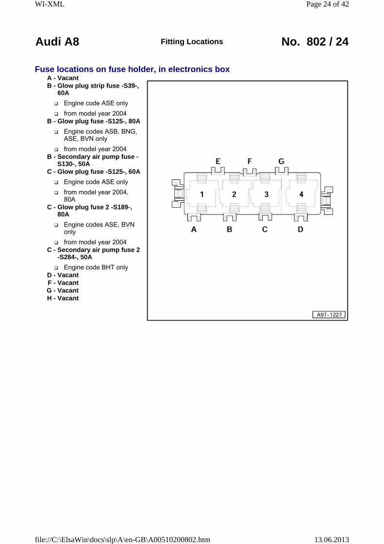
Fuse locations on fuse holder, in electronics boxA - VacantB - Glow plug strip fuse -S39-,
60A
Engine code ASE only
from model year 2004B - Glow plug fuse -S125-, 80A
Engine codes ASB, BNG, ASE, BVN only
from model year 2004B - Secondary air pump fuse -
S130-, 50AC - Glow plug fuse -S125-, 60A
Engine code ASE only
from model year 2004, 80A
C - Glow plug fuse 2 -S189-, 80A
Engine codes ASE, BVN only
from model year 2004C - Secondary air pump fuse 2
-S284-, 50A
Engine code BHT onlyD - VacantF - VacantG - VacantH - Vacant
Page 24 of 42WI-XML
13.06.2013file://C:\ElsaWin\docs\slp\A\en-GB\A00510200802.htm
Audi A8 Fitting Locations No. 802 / 25
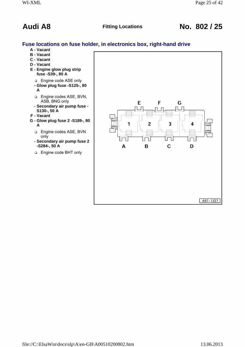
Fuse locations on fuse holder, in electronics box, right-hand driveA - VacantB - VacantC - VacantD - VacantE - Engine glow plug strip
fuse -S39-, 80 A
Engine code ASE only - Glow plug fuse -S125-, 80
A
Engine codes ASE, BVN, ASB, BNG only
- Secondary air pump fuse -S130-, 50 A
F - VacantG - Glow plug fuse 2 -S189-, 80
A
Engine codes ASE, BVN only
- Secondary air pump fuse 2 -S284-, 50 A
Engine code BHT only
Page 25 of 42WI-XML
13.06.2013file://C:\ElsaWin\docs\slp\A\en-GB\A00510200802.htm

Audi A8 Fitting Locations No. 802 / 26
Position of fuses on fuse holder, on left behind dash panelA - ABS control unit fuse 1 -
S123-, 60AB - Levelling system fuse -
S110- 40AC - Window regulator thermal
fuse -S43- 40A
from model year 2004, 30A
D - Seat adjustment thermal fuse 1 -S44-, 30A
E - Seat adjustment thermal fuse 2 -S45- 30A
F - VacantG - VacantH - Vacant
Page 26 of 42WI-XML
13.06.2013file://C:\ElsaWin\docs\slp\A\en-GB\A00510200802.htm
Audi A8 Fitting Locations No. 802 / 27
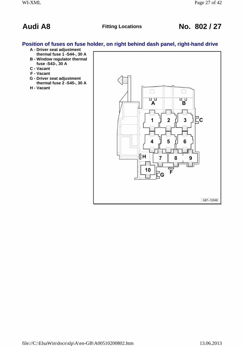
Position of fuses on fuse holder, on right behind dash panel, right-hand driveA - Driver seat adjustment
thermal fuse 1 -S44-, 30 AB - Window regulator thermal
fuse -S43-, 30 AC - VacantF - VacantG - Driver seat adjustment
thermal fuse 2 -S45-, 30 AH - Vacant
Page 27 of 42WI-XML
13.06.2013file://C:\ElsaWin\docs\slp\A\en-GB\A00510200802.htm
Audi A8 Fitting Locations No. 802 / 28
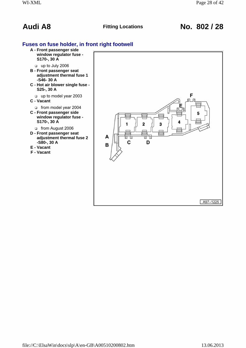
Fuses on fuse holder, in front right footwellA - Front passenger side
window regulator fuse -S170-, 30 A
up to July 2006B - Front passenger seat
adjustment thermal fuse 1 -S46- 30 A
C - Hot air blower single fuse -S25-, 30 A
up to model year 2003C - Vacant
from model year 2004C - Front passenger side
window regulator fuse -S170-, 30 A
from August 2006D - Front passenger seat
adjustment thermal fuse 2 -S80-, 30 A
E - VacantF - Vacant
Page 28 of 42WI-XML
13.06.2013file://C:\ElsaWin\docs\slp\A\en-GB\A00510200802.htm
Audi A8 Fitting Locations No. 802 / 29
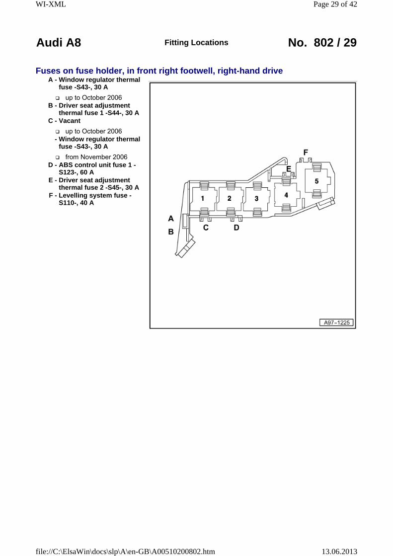
Fuses on fuse holder, in front right footwell, right-hand driveA - Window regulator thermal
fuse -S43-, 30 A
up to October 2006B - Driver seat adjustment
thermal fuse 1 -S44-, 30 AC - Vacant
up to October 2006 - Window regulator thermal
fuse -S43-, 30 A
from November 2006D - ABS control unit fuse 1 -
S123-, 60 AE - Driver seat adjustment
thermal fuse 2 -S45-, 30 AF - Levelling system fuse -
S110-, 40 A
Page 29 of 42WI-XML
13.06.2013file://C:\ElsaWin\docs\slp\A\en-GB\A00510200802.htm

Audi A8 Fitting Locations No. 802 / 30
Position of fuses on main fuse carrier, right A-pillar1 - Radiator fan single fuse -
S42-, 60A1A - Screw point radiator fan
2 - Radiator fan fuse for 2nd speed -S104-, 60A
2A - Screw point radiator fan fuse for 2nd speed
3 - Terminal 30 screw point (battery)
4 - Terminal 30 screw point (starter)
Page 30 of 42WI-XML
13.06.2013file://C:\ElsaWin\docs\slp\A\en-GB\A00510200802.htm
Audi A8 Fitting Locations No. 802 / 31
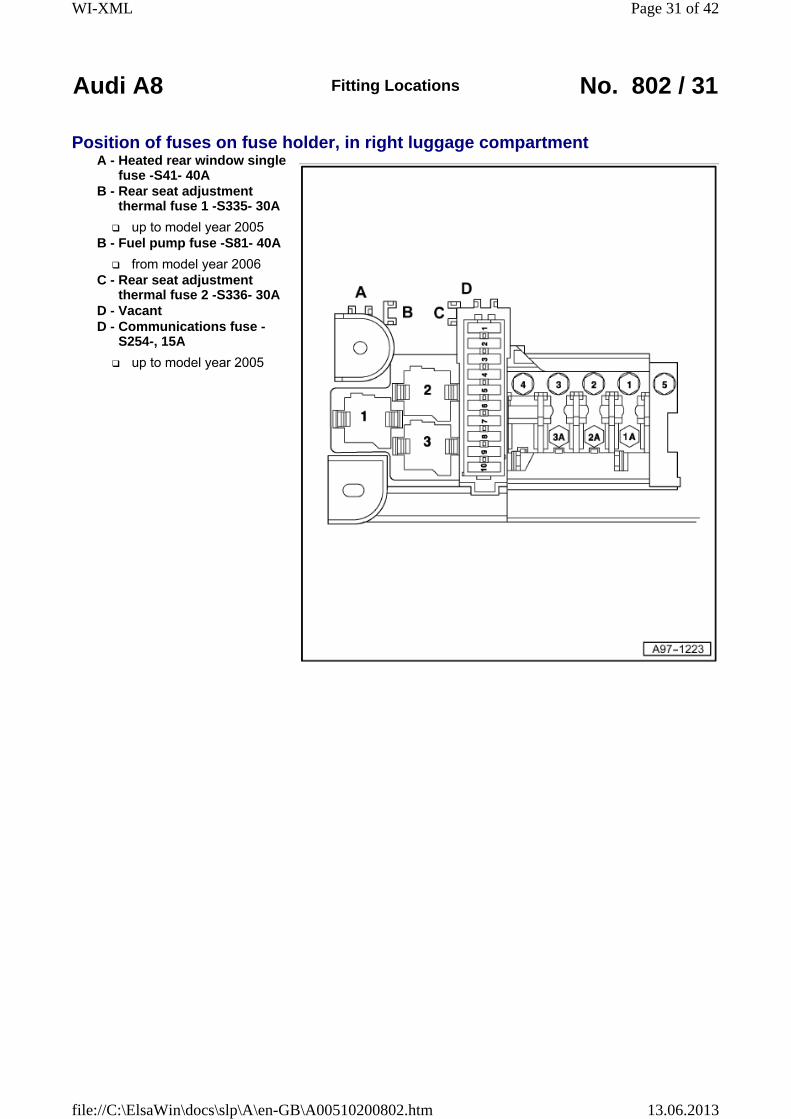
Position of fuses on fuse holder, in right luggage compartmentA - Heated rear window single
fuse -S41- 40AB - Rear seat adjustment
thermal fuse 1 -S335- 30A
up to model year 2005B - Fuel pump fuse -S81- 40A
from model year 2006C - Rear seat adjustment
thermal fuse 2 -S336- 30AD - VacantD - Communications fuse -
S254-, 15A
up to model year 2005
Page 31 of 42WI-XML
13.06.2013file://C:\ElsaWin\docs\slp\A\en-GB\A00510200802.htm
Audi A8 Fitting Locations No. 802 / 32
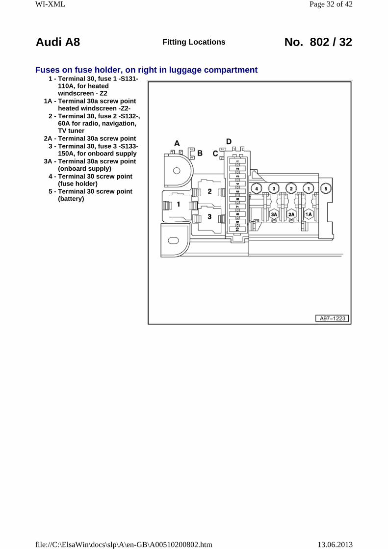
Fuses on fuse holder, on right in luggage compartment1 - Terminal 30, fuse 1 -S131-
110A, for heated windscreen - Z2
1A - Terminal 30a screw point heated windscreen -Z2-
2 - Terminal 30, fuse 2 -S132-, 60A for radio, navigation, TV tuner
2A - Terminal 30a screw point3 - Terminal 30, fuse 3 -S133-
150A, for onboard supply3A - Terminal 30a screw point
(onboard supply)4 - Terminal 30 screw point
(fuse holder)5 - Terminal 30 screw point
(battery)
Page 32 of 42WI-XML
13.06.2013file://C:\ElsaWin\docs\slp\A\en-GB\A00510200802.htm

Audi A8 Fitting Locations No. 802 / 33
Position of fuses (SF) on fuse holder, on right in luggage compartment, up to model year 2003
- SF1 - Convenience system central control unit -J393-, left light, 20A
SF2 - Convenience system central control unit -J393-, right light, 10A
- SF3 - Convenience system central control unit -J393-, power latching system, 20A
- SF4 - Electric park and handbrake control unit -J540-, left parking brake motor -V282-, 30A
- SF5 - Electric park and handbrake control unit -J540-, right parking brake motor -V283-, 30A
- SF6 - Trailer detector control unit -J345-, left light, 15A
- SF7 - Trailer detector control unit -J345-, right light, 15A
- SF8 - Trailer detector control unit -J345-, 10A
- SF9 - Fuel pump -G23-, 20A
- SF10 - Fuel system pressurisation pump -G6-, 20A
Page 33 of 42WI-XML
13.06.2013file://C:\ElsaWin\docs\slp\A\en-GB\A00510200802.htm
Audi A8 Fitting Locations No. 802 / 34
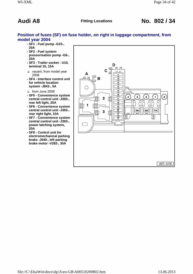
Position of fuses (SF) on fuse holder, on right in luggage compartment, from model year 2004
- SF1 - Fuel pump -G23-, 20A
- SF2 - Fuel system pressurisation pump -G6-, 20A
- SF3 - Trailer socket - U10, terminal 15, 15A
vacant, from model year 2006
- SF4 - Interface control unit for vehicle location system -J843-, 5A
from June 2008 - SF5 - Convenience system
central control unit -J393-, rear left light, 20A
- SF6 - Convenience system central control unit -J393-, rear right light, 10A
- SF7 - Convenience system central control unit -J393-, power latching system, 20A
- SF8 - Control unit for electromechanical parking brake -J540-, left parking brake motor -V282-, 30A
Page 34 of 42WI-XML
13.06.2013file://C:\ElsaWin\docs\slp\A\en-GB\A00510200802.htm
Audi A8 Fitting Locations No. 802 / 35
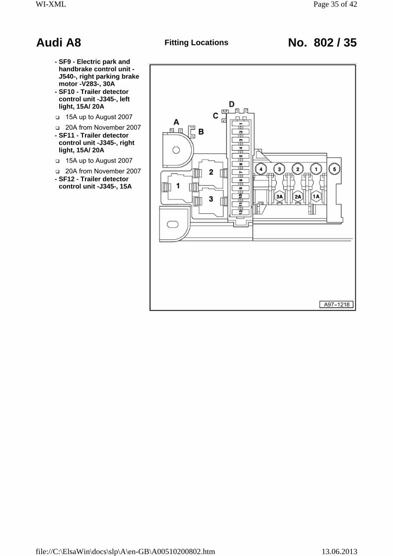
- SF9 - Electric park and handbrake control unit -J540-, right parking brake motor -V283-, 30A
- SF10 - Trailer detector control unit -J345-, left light, 15A/ 20A
15A up to August 2007
20A from November 2007 - SF11 - Trailer detector
control unit -J345-, right light, 15A/ 20A
15A up to August 2007
20A from November 2007 - SF12 - Trailer detector
control unit -J345-, 15A
Page 35 of 42WI-XML
13.06.2013file://C:\ElsaWin\docs\slp\A\en-GB\A00510200802.htm
Audi A8 Fitting Locations No. 802 / 36
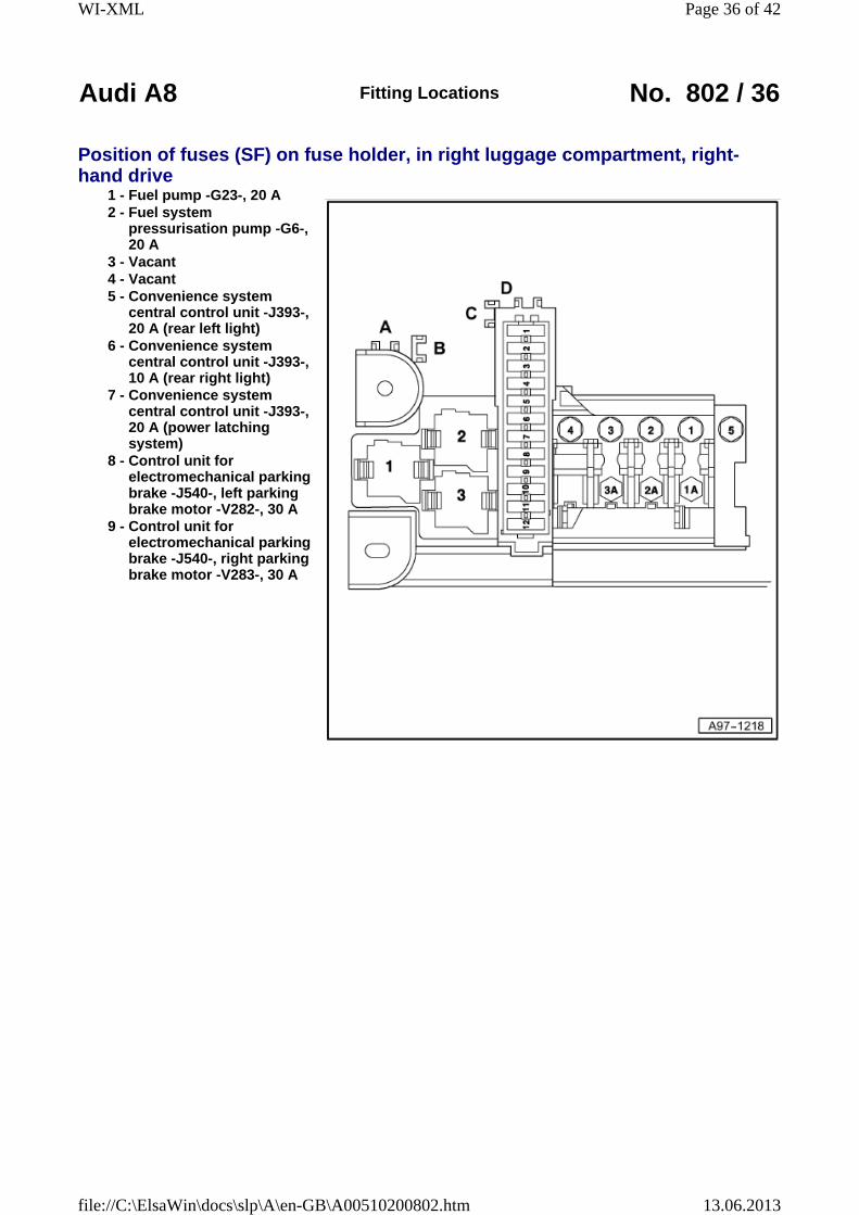
Position of fuses (SF) on fuse holder, in right luggage compartment, right-hand drive
1 - Fuel pump -G23-, 20 A2 - Fuel system
pressurisation pump -G6-, 20 A
3 - Vacant4 - Vacant5 - Convenience system
central control unit -J393-, 20 A (rear left light)
6 - Convenience system central control unit -J393-, 10 A (rear right light)
7 - Convenience system central control unit -J393-, 20 A (power latching system)
8 - Control unit for electromechanical parking brake -J540-, left parking brake motor -V282-, 30 A
9 - Control unit for electromechanical parking brake -J540-, right parking brake motor -V283-, 30 A
Page 36 of 42WI-XML
13.06.2013file://C:\ElsaWin\docs\slp\A\en-GB\A00510200802.htm

Audi A8 Fitting Locations No. 802 / 37
10 - Trailer detector control unit -J345-, 20A (left light)
11 - Trailer detector control unit -J345-, 20A (right light)
12 - Trailer detector control unit -J345-, 15 A
Page 37 of 42WI-XML
13.06.2013file://C:\ElsaWin\docs\slp\A\en-GB\A00510200802.htm
Audi A8 Fitting Locations No. 802 / 38
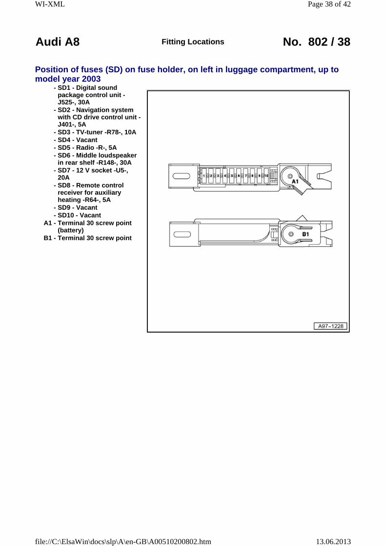
Position of fuses (SD) on fuse holder, on left in luggage compartment, up to model year 2003
- SD1 - Digital sound package control unit -J525-, 30A
- SD2 - Navigation system with CD drive control unit -J401-, 5A
- SD3 - TV-tuner -R78-, 10A - SD4 - Vacant - SD5 - Radio -R-, 5A - SD6 - Middle loudspeaker
in rear shelf -R148-, 30A - SD7 - 12 V socket -U5-,
20A - SD8 - Remote control
receiver for auxiliary heating -R64-, 5A
- SD9 - Vacant - SD10 - Vacant
A1 - Terminal 30 screw point (battery)
B1 - Terminal 30 screw point
Page 38 of 42WI-XML
13.06.2013file://C:\ElsaWin\docs\slp\A\en-GB\A00510200802.htm

Audi A8 Fitting Locations No. 802 / 39
Position of fuses (SD) on fuse holder, on left in luggage compartment, from model year 2004
- SD1 - Vacant - SD2 - Vacant - SD3 - Vacant - SD4 - Vacant - SD5 - Digital sound
package control unit -J525-, 30A
- SD6 - Navigation system with CD drive control unit -J401-, 5A
- SD7 - TV-tuner -R78-, digital TV tuner -R171-, 10A
- SD8 - Reversing camera system control unit -J772-, 5A
vacant, up to model year 2007
- SD9 - Radio -R-, digital radio -R147-, satellite radio -R146-, 5A
-R146- only USA
up to August 2008 - SD9 - Radio -R-, 25A
from September 2008 - SD10 - Middle loudspeaker
-R148-, 15A
Page 39 of 42WI-XML
13.06.2013file://C:\ElsaWin\docs\slp\A\en-GB\A00510200802.htm

Audi A8 Fitting Locations No. 802 / 40
- SD10 - Digital sound package control unit 2 -J787-, 30A
only BANG and OLUFSEN
- SD11 - 12 V socket -U5-, 20A
- SD12 - Remote control receiver for auxiliary heating -R64-, 5A
A1 - Terminal 30 screw point (battery)
B1 - Terminal 30 screw point (fuse holder)
Page 40 of 42WI-XML
13.06.2013file://C:\ElsaWin\docs\slp\A\en-GB\A00510200802.htm

Audi A8 Fitting Locations No. 802 / 41
Position fuse holder on left in luggage compartment, right-hand drive - SD1 - Vacant - SD2 - Vacant - SD3 - Vacant - SD4 - Vacant - SD5 - Digital sound
package control unit -J525-, 30A
- SD6 - Navigation system with CD drive control unit -J401-, 5A
- SD7 - TV-tuner -R78-, 10A - SD8 - Reversing camera
system control unit -J772-, 5A
- SD9 - Radio -R-, digital radio -R147-, satellite radio -R146-, 5A
-R146- only USA
up to August 2008 - SD9 - Radio -R-, 25A
from September 2008
Page 41 of 42WI-XML
13.06.2013file://C:\ElsaWin\docs\slp\A\en-GB\A00510200802.htm

Audi A8 Fitting Locations No. 802 / 42
- SD10 - Middle loudspeaker - R148, 15 A
- Digital sound package control unit 2 -J787-, 30 A
only BANG and OLUFSEN
- SD11 - 12 V socket -U5-, 20 A
- SD12 - Remote control receiver for auxiliary heating -R64-, 5 A
A1 - Terminal 30 screw point (battery)
B1 - Terminal 30 screw point (fuse holder)
Page 42 of 42WI-XML
13.06.2013file://C:\ElsaWin\docs\slp\A\en-GB\A00510200802.htm