Aubin Academy Master Series - Amazon S3 · 2019-10-20 · Appendix Preface to the Appendix WELCOME...
18
The Aubin Academy Master Series AutoCAD MEP Compatible with versions 2012, 2013 and beyond Appendix A Paul F Aubin Darryl McClelland, LEED AP Martin Schmid, PE Gregg Stanley G3B • Press
Transcript of Aubin Academy Master Series - Amazon S3 · 2019-10-20 · Appendix Preface to the Appendix WELCOME...
The Aubin Academy Master Series
AutoCAD MEP Compatible with versions 2012, 2013 and beyond
Appendix A
Paul F Aubin Darryl McClelland, LEED AP
Martin Schmid, PE Gregg Stanley
G3B • Press

The Aubin Academy Master Series: AutoCAD MEP compatible with versions 2012, 2013 and beyond Paul F. Aubin, Darryl McClelland, LEED AP, Martin Schmid, PE, and Gregg Stanley
© 2012 Paul F. Aubin
ALL RIGHTS RESERVED. No part of this work covered by the copyright herein may be reproduced, transmitted. stored. or used in any form or by any means graphic, electronic, or mechanical. including but not limited to photocopying, recording, scanning, digitizing, taping, Web distribution, information networks, or information storage and retrieval systems, except as permitted under Section 107 or 108 of the 1976 United States Copyright Act, Without the prior written permission of the publisher.
ISBN-13: 978-1479338979 ISBN-10: 1479338974
G3B Press c/o Paul F. Aubin Consulting Services P.O. Box 223 Oak Lawn, IL 60454 USA
To learn more about titles by G3B Press, the book’s authors and other offerings by Paul F Aubin Consulting Services, please visit www.paulaubin.com. Updates are posted to the blog section of the site. Please use Contact link to send email.
Notice to the Reader Publisher does not warrant or guarantee any of the products described herein or perform any independent analysis in connection with any of the product information contained herein. Publisher does not assume, and expressly disclaims, any obligation to obtain and include information other than that provided to it by the manufacturer. The reader is expressly warned to consider and adopt all safety precautions that might be indicated by the activities described herein and to avoid all potential hazards. By following the instructions contained herein, the reader willingly assumes all risks in connection with such instructions. The publisher makes no representations or warranties of any kind, including but not limited to, the warranties of fitness for particular purpose or merchantability, nor are any such representations implied with respect to the material set forth herein, and the publisher takes no responsibility with respect to such material. The publisher shall not be liable for any special, consequential, or exemplary damages resulting, in whole or part, from the readers’ use of, or reliance upon, this material. The views expressed herein are solely those of the authors/presenters and are not those of Autodesk, Inc., its officers, directors, subsidiaries, affiliates, business partners, or customers.
Contents of The Aubin Academy Master Series: AutoCAD MEP
Preface ............................................................................................................... xiii
SECTION I—INTRODUCTION AND METHODOLOGY
Chapter 1—The User Interface ............................................................................... 3
Chapter 2—Conceptual Underpinnings of AutoCAD MEP ..................................... 57
Chapter 3—Project Navigator for MEP ...............................................................113
SECTION II—WORKING WITH MEP OBJECTS
Chapter 4—Energy Analysis ...............................................................................187
Chapter 5—Mechanical Systems ........................................................................245
Chapter 6—Piping Systems ................................................................................313
Chapter 7—Electrical Systems Layout ................................................................399
Chapter 8—Conduit Systems..............................................................................475
SECTION III—CONTENT AND DISPLAY
Chapter 9—Content Creation—Styles .................................................................501
Chapter 10—Content Creation—Equipment .......................................................557
Chapter 11—Content Creation—Parametric Fittings...........................................593
Chapter 12—Display System ..............................................................................639
SECTION IV—DOCUMENTATION AND COORDINATION
Chapter 13—Sections ........................................................................................671
Chapter 14—Managing Updates and Interference Detection ..............................701
Chapter 15—Annotation, Property Sets, and Schedules .....................................723
Index..................................................................................................... 786

Appendix
Preface to the Appendix
WELCOME Thank you for downloading Appendix. This PDF accompanys The Aubin Academy Master Series: AutoCAD MEP and is not included in the physical book’s chapters. It is only available in this digital format. This chapter is authored in the 2012 version, but you will find it compatible with previous versions as well. There is no dataset needed for this appendix.
If you do not have a copy of The Aubin Academy Master Series: AutoCAD MEP, please consider visiting www.paulaubin.com to learn how to order a copy today. References are made in the text of this chapter to other chapters in the physical book. This appendix has been titled A and occurs after the physical book’s chapters. If you have a copy of the book, there are a few references to this appendix included. We hope you find this bonus appendix uesful.
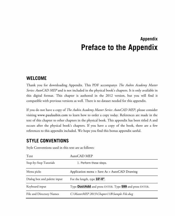
STYLE CONVENTIONS Style Conventions used in this text are as follows:
Text AutoCAD MEP
Step-by-Step Tutorials 1. Perform these steps.
Menu picks Application menu > Save As > AutoCAD Drawing
Dialog box and palette input For the length, type 10'-0".
Keyboard input Type DuctAdd and press ENTER. Type 599 and press ENTER.
File and Directory Names C:\MasterMEP 2013\Chapter11B\Sample File.dwg

2 | Preface to the Appendix
UNITS This book is written in Imperial units. Metric datasets and references are not provided.
BOOK DATASET FILES No files are referenced in this appendix.
WE WANT TO HEAR FROM YOU We welcome your comments and suggestions regarding this and and any of our books. Please visit www.paulaubin.com and click the Contact link to send an email using the form provided. You can reach all four authors using this form. Also be sure to visit the blog as updates to the book’s content will be posted there as soon as they become available.
ABOUT THE AUTHORS Paul F. Aubin is the author of many CAD and BIM book titles including the widely acclaimed: The Aubin Academy Mastering Series: Revit Architecture, AutoCAD Architecture, AutoCAD MEP and Revit MEP titles. Paul has also authored several video training courses for lynda.com (www.lynda.com/paulaubin). Paul is an independent architectural consultant who travels internationally providing Revit® Architecture and AutoCAD® Architecture implementation, training, and support services. Paul’s involvement in the architectural profession spans over 20 years, with experience that includes design, production, CAD management, mentoring, coaching and training. He is an active member of the Autodesk user community, and has been a top-rated speaker at Autodesk University (Autodesk’s annual user convention) for many years. Paul has also received high ratings at the Revit Technology Conference (RTC) in both the US and Australia and he spoke at the inaugural Central States Revit Workshop this year. His diverse experience in architectural firms, as a CAD manager, and as an educator gives his writing and his classroom instruction a fresh and credible focus. Paul is an associate member of the American Institute of Architects. He lives in Chicago with his wife and three children.
Darryl McClelland, LEED AP has 27 years of practical design experience in MEP engineering. Although his primary focus was the design of mechanical systems, he spent 11 of those 27 years designing electrical and plumbing systems as well. He also ran his own engineering business for eight years. His design experience ranges from complex research
Appendix

0 | 3
laboratories and institutional facilities to medical and professional office buildings, and everything in between. He is a graduate of Purdue University and an active member of ASHRAE, ASPE, and a LEED AP.
Martin J. Schmid, P.E. is focused on the application of model based design tools to facilitate analysis, and the adoption of such tools around the world. Mr. Schmid has worked in various roles in a variety of architecture and engineering firms, including electrical designer, engineering coordinator, and application developer. In addition to product and industry expertise, Mr. Schmid applies the API’s of Autodesk’s products to automate processes and solve customer problems. Mr. Schmid has presented internally to coworkers, at Autodesk University, industry conferences, and as a consultant to design firms and 3rd party application developers.
Gregg Stanley has over twenty years’ experience in Software and Water Wastewater treatment industries focused on providing clients complete solutions for their projects. Gregg’s extensive background in Mechanical Process design and construction coordination provides a customer focused approach to creating this book on AutoCAD MEP’s functionality. Gregg’s background is in Mechanical Process design and software testing, Design and Product management utilizing a customer focused approach. He is also an experienced instructor, teaching over 30 different courses for software implementation and use.
The views expressed herein are solely those of the authors/presenters and are not those of Autodesk, Inc., its officers, directors, subsidiaries, affiliates, business partners, or customers.
Cover Design: Michael Brumm
Author Illustrations: Ron Bailey
Cover Artwork: iStockphoto.com

Appendix A
Rise Drop Styles
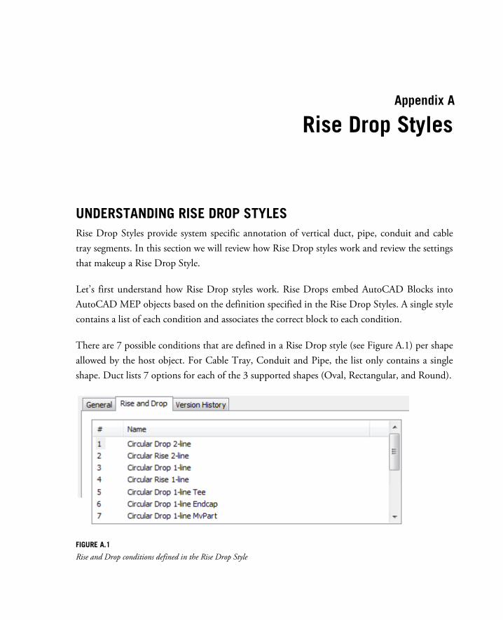
UNDERSTANDING RISE DROP STYLES Rise Drop Styles provide system specific annotation of vertical duct, pipe, conduit and cable tray segments. In this section we will review how Rise Drop styles work and review the settings that makeup a Rise Drop Style.
Let’s first understand how Rise Drop styles work. Rise Drops embed AutoCAD Blocks into AutoCAD MEP objects based on the definition specified in the Rise Drop Styles. A single style contains a list of each condition and associates the correct block to each condition.
There are 7 possible conditions that are defined in a Rise Drop style (see Figure A.1) per shape allowed by the host object. For Cable Tray, Conduit and Pipe, the list only contains a single shape. Duct lists 7 options for each of the 3 supported shapes (Oval, Rectangular, and Round).
FIGURE A.1
Rise and Drop conditions defined in the Rise Drop Style

6 | Rise Drop Styles
Each condition is defined by the settings in the Rise Drop Style. There are five groups of settings that need to be defined to specify a Rise Drop Style (see Figure A.2). Each will be described in a numbered heading that follows.
1. Symbol Definition 2. Shape 3. Define Rise or Drop condition 4. Override the scaling of the Rise / Drop block 5. Specify the relative scale for the Center Line block associated symbol.
FIGURE A.2
Rise and Drop conditions defined in the Rise Drop Style
Supplement to The Aubin Academy Master Series: AutoCAD MEP
Appendix | 7
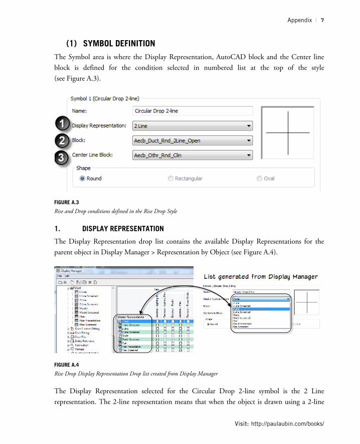
(1) SYMBOL DEFINITION The Symbol area is where the Display Representation, AutoCAD block and the Center line block is defined for the condition selected in numbered list at the top of the style (see Figure A.3).
FIGURE A.3
Rise and Drop conditions defined in the Rise Drop Style
1. DISPLAY REPRESENTATION
The Display Representation drop list contains the available Display Representations for the parent object in Display Manager > Representation by Object (see Figure A.4).
FIGURE A.4
Rise Drop Display Representation Drop list created from Display Manager
The Display Representation selected for the Circular Drop 2-line symbol is the 2 Line representation. The 2-line representation means that when the object is drawn using a 2-line
Visit: http://paulaubin.com/books/

8 | Rise Drop Styles
display representation and is in a drop condition (the object’s connector is pointing down) this symbol will be embedded into the object.
2. BLOCK
The block drop list contains all available blocks inside the current drawing. AutoCAD MEP templates contain multiple AutoCAD blocks to be used as Rise Drop Symbols. These blocks are formatted to be identified as Rise Drop blocks. The format used is (see Figure RD.A.5): Aecb_Domain_Shape_Display Representation_System Type_Condition.
The block used in the Rise Drop style will be embedded on the object and assigned to the Rise Drop Display Component associated with the object. For more information on the Display System, please refer to Chapter 12.
FIGURE A.5
Rise Drop blocks
The selected block will appear in the preview with the selected Center line block.
Supplement to The Aubin Academy Master Series: AutoCAD MEP
Appendix | 9
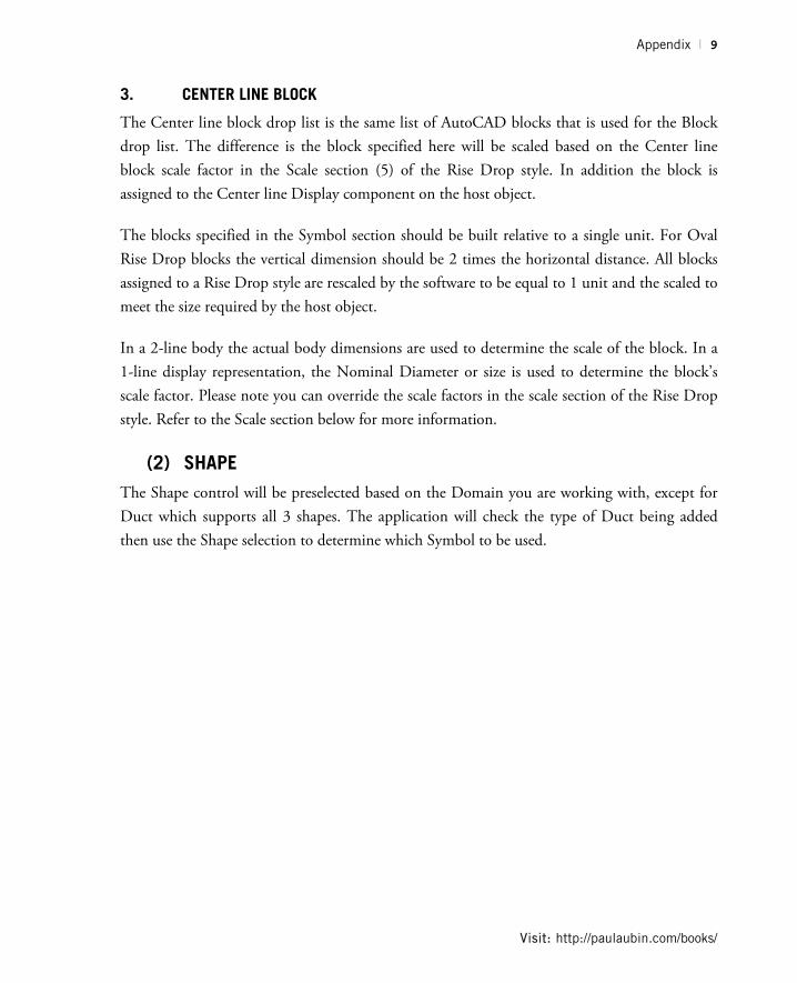
3. CENTER LINE BLOCK
The Center line block drop list is the same list of AutoCAD blocks that is used for the Block drop list. The difference is the block specified here will be scaled based on the Center line block scale factor in the Scale section (5) of the Rise Drop style. In addition the block is assigned to the Center line Display component on the host object.
The blocks specified in the Symbol section should be built relative to a single unit. For Oval Rise Drop blocks the vertical dimension should be 2 times the horizontal distance. All blocks assigned to a Rise Drop style are rescaled by the software to be equal to 1 unit and the scaled to meet the size required by the host object.
In a 2-line body the actual body dimensions are used to determine the scale of the block. In a 1-line display representation, the Nominal Diameter or size is used to determine the block’s scale factor. Please note you can override the scale factors in the scale section of the Rise Drop style. Refer to the Scale section below for more information.
(2) SHAPE The Shape control will be preselected based on the Domain you are working with, except for Duct which supports all 3 shapes. The application will check the type of Duct being added then use the Shape selection to determine which Symbol to be used.
Visit: http://paulaubin.com/books/
10 | Rise Drop Styles
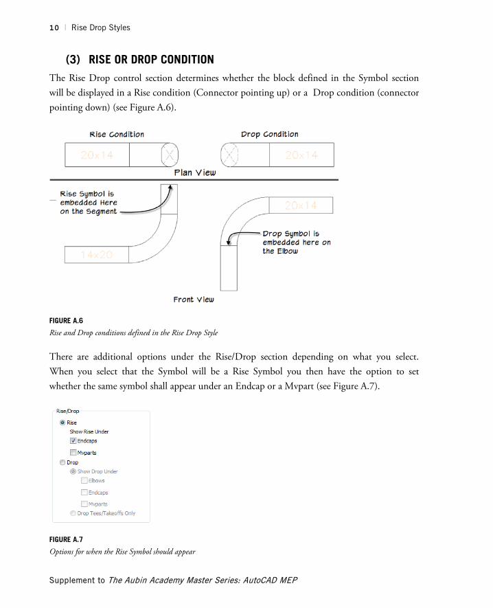
(3) RISE OR DROP CONDITION The Rise Drop control section determines whether the block defined in the Symbol section will be displayed in a Rise condition (Connector pointing up) or a Drop condition (connector pointing down) (see Figure A.6).
FIGURE A.6
Rise and Drop conditions defined in the Rise Drop Style
There are additional options under the Rise/Drop section depending on what you select. When you select that the Symbol will be a Rise Symbol you then have the option to set whether the same symbol shall appear under an Endcap or a Mvpart (see Figure A.7).
FIGURE A.7
Options for when the Rise Symbol should appear
Supplement to The Aubin Academy Master Series: AutoCAD MEP
Appendix | 11
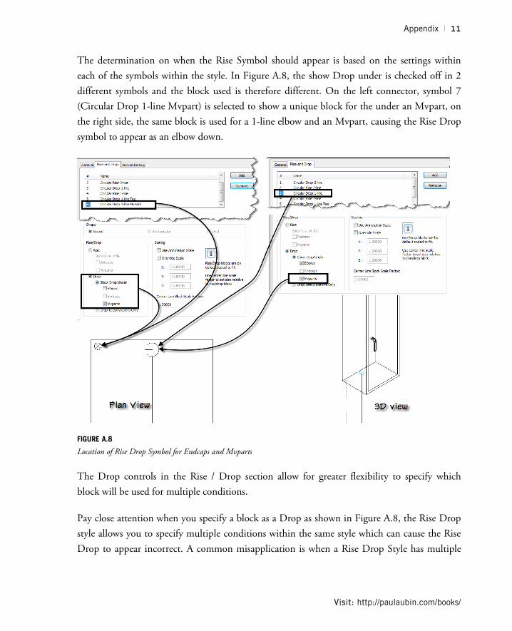
The determination on when the Rise Symbol should appear is based on the settings within each of the symbols within the style. In Figure A.8, the show Drop under is checked off in 2 different symbols and the block used is therefore different. On the left connector, symbol 7 (Circular Drop 1-line Mvpart) is selected to show a unique block for the under an Mvpart, on the right side, the same block is used for a 1-line elbow and an Mvpart, causing the Rise Drop symbol to appear as an elbow down.
FIGURE A.8
Location of Rise Drop Symbol for Endcaps and Mvparts
The Drop controls in the Rise / Drop section allow for greater flexibility to specify which block will be used for multiple conditions.
Pay close attention when you specify a block as a Drop as shown in Figure A.8, the Rise Drop style allows you to specify multiple conditions within the same style which can cause the Rise Drop to appear incorrect. A common misapplication is when a Rise Drop Style has multiple
Visit: http://paulaubin.com/books/
12 | Rise Drop Styles
conditions specified for Mvpart or Endcaps, causing two or more blocks to be nested within the display of a particular Rise Drop condition.
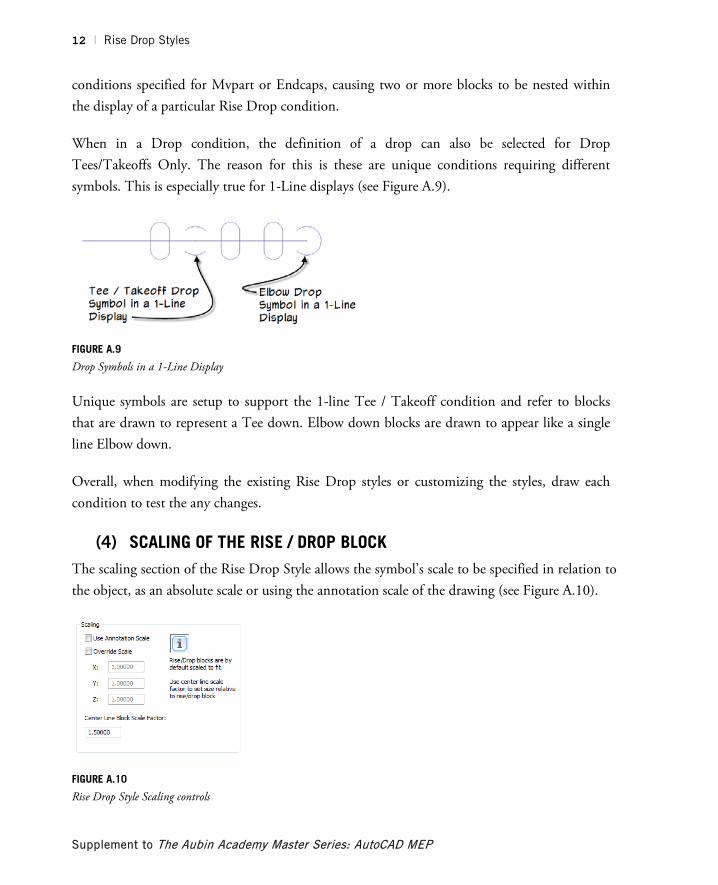
When in a Drop condition, the definition of a drop can also be selected for Drop Tees/Takeoffs Only. The reason for this is these are unique conditions requiring different symbols. This is especially true for 1-Line displays (see Figure A.9).
FIGURE A.9
Drop Symbols in a 1-Line Display
Unique symbols are setup to support the 1-line Tee / Takeoff condition and refer to blocks that are drawn to represent a Tee down. Elbow down blocks are drawn to appear like a single line Elbow down.
Overall, when modifying the existing Rise Drop styles or customizing the styles, draw each condition to test the any changes.
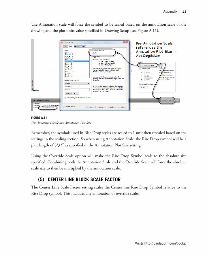
(4) SCALING OF THE RISE / DROP BLOCK The scaling section of the Rise Drop Style allows the symbol’s scale to be specified in relation to the object, as an absolute scale or using the annotation scale of the drawing (see Figure A.10).
FIGURE A.10
Rise Drop Style Scaling controls
Supplement to The Aubin Academy Master Series: AutoCAD MEP
Appendix | 13
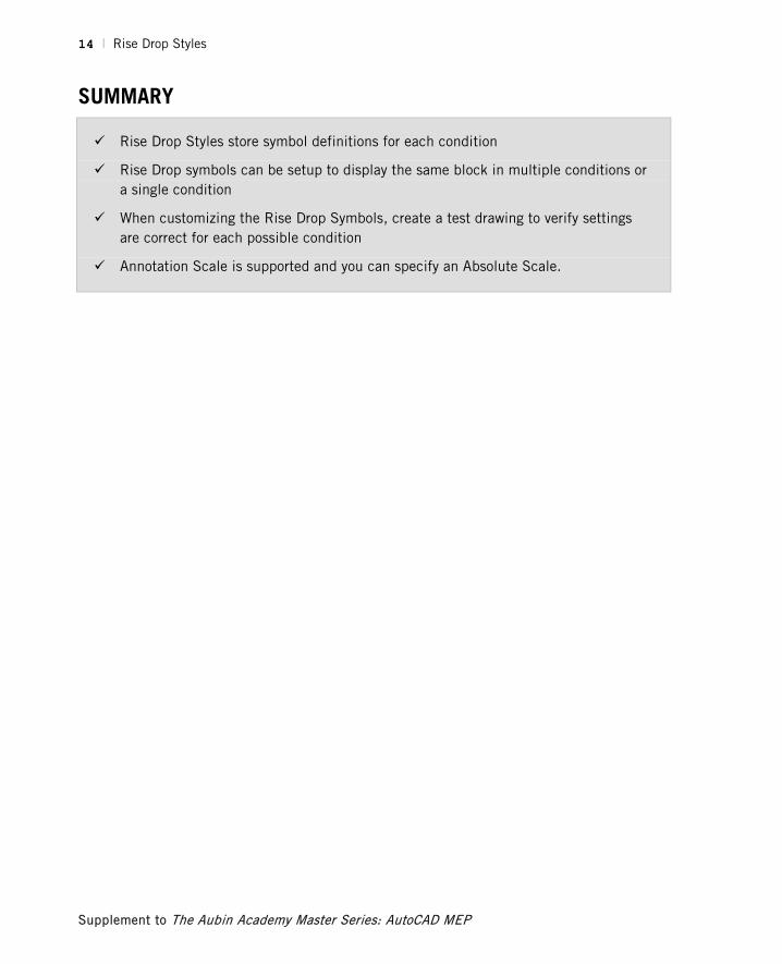
Use Annotation scale will force the symbol to be scaled based on the annotation scale of the drawing and the plot units value specified in Drawing Setup (see Figure A.11).
FIGURE A.11
Use Annotation Scale uses Annotation Plot Size
Remember, the symbols used in Rise Drop styles are scaled to 1 unit then rescaled based on the settings in the scaling section. So when using Annotation Scale, the Rise Drop symbol will be a plot length of 3/32” as specified in the Annotation Plot Size setting.
Using the Override Scale option will make the Rise Drop Symbol scale to the absolute size specified. Combining both the Annotation Scale and the Override Scale will force the absolute scale size to then be multiplied by the annotation scale.
(5) CENTER LINE BLOCK SCALE FACTOR The Center Line Scale Factor setting scales the Center line Rise Drop Symbol relative to the Rise Drop symbol, This includes any annotation or override scales
Visit: http://paulaubin.com/books/
14 | Rise Drop Styles
SUMMARY
Rise Drop Styles store symbol definitions for each condition
Rise Drop symbols can be setup to display the same block in multiple conditions or a single condition
When customizing the Rise Drop Symbols, create a test drawing to verify settings are correct for each possible condition
Annotation Scale is supported and you can specify an Absolute Scale.
Supplement to The Aubin Academy Master Series: AutoCAD MEP