ATTO FibreBridge Installation and Operation Manual · ATTO FibreBridge™ Installation and...
28
ATTO FibreBridge ™ Installation and Operation Manual ATTO FibreBridge 7500N 16-Gigabit Fibre Channel to 12-Gigabit SAS Storage Controller
Transcript of ATTO FibreBridge Installation and Operation Manual · ATTO FibreBridge™ Installation and...

ATTO FibreBridge™
Installation and Operation ManualATTO FibreBridge 7500N
16-Gigabit Fibre Channel to 12-Gigabit SAS Storage Controller

ATTO Technology, Inc.155 CrossPoint ParkwayAmherst, New York 14068 USA
www.attotech.com
Tel (716) 691-1999Fax (716) 691-9353
Sales support: [email protected] support: Please visit https://www.attotech.com/support/ for hours of operation.
[email protected] (716)691-1999 ext. 242
© 2015 ATTO Technology, Inc. All rights reserved. All brand or product names are trademarks of their respective holders. No part of this manual may be reproduced in any form or by any means without the express written permission of ATTO Technology, Inc.
12/2015.............................................................................................................................................. PRMA-0468-000MD

Contents
1.0 ATTO FibreBridge Overview .........................................................................1ATTO FibreBridge 7500N features, benefits
1.1 ATTO FibreBridge 7500N ...............................................................................2DimensionsCooling and airflowPower FibreChannel portsSAS portsManagement portsLED indicators
2.0 Install the FibreBridge ...................................................................................4Unpack the packing box, verify contents Install the FibreBridgeInstallation and Removal of Power Supply ModulesConfigure an Ethernet Management PortInternet Explorer setup
3.0 Configure the FibreBridge ............................................................................6Preliminary stepsPort configurationsModify passwordsSet Time & DateSet SNMP Trap Recipients
4.0 Interface options ............................................................................................9Using ExpressNAV System ManagerUsing the serial portUsing Telnet
5.0 Update Firmware ............................................................................................11Using ExpressNAVUsing FTP

Appendices
Appendix A Cabling ..............................................................................................iSerial port connectionsEthernet connections
Appendix B CLI provides ASCII-based Interface ...............................................iiCLI error messagesCLI summary referenceCommand explanations
Appendix C Standards and Compliances ...........................................................ixRegulatory NoticesFCC Notices (US only)Compliance with ICES-003Compliance with EN Regulations
Appendix D Warranty Information .......................................................................xi

1
1.0 ATTO FibreBridge Overview The ATTO FibreBridge™ is a performance tuned intelligent protocol translator which allows upstream initiators connected via Fibre Channel to communicate with downstream targets connected via SAS. FibreBridge products are fitted for rack mount integration.
Fibre Channel is a serial communications technology designed to transfer large amounts of data between a variety of hardware systems over long distances. It is a key technology for applications that require shared, high bandwidth access to storage.
Fibre Channel provides a logical point-to-point serial channel for the transfer of data between a buffer at a source device and a buffer at a destination device. It moves buffer contents from one port to another, without regard to the format or meaning of the data, so different upper level protocols are able to run over Fibre Channel hardware.
Serial Attached SCSI (SAS) is an industry standard specification whose architecture consists of a multi-layer definition including three transport protocols for supporting initiator communication with end-
point devices and SAS expanders. The SAS connection model enables aggregation of physical links forming a logical point-to-point serial channel for transfer of data between SAS initiators and target end-point devices. The physical layer supports data rates of 6Gb/s and 12 Gb/s.
The ATTO FibreBridge 7500N bridges upstream initiators connected via FC to downstream end-point devices connected via SAS. On the upstream side, direct attachment to vendor specified host system FC HBAs and fabric attachment to vendor specified FC switches are supported. On the downstream side, the FibreBridge 7500N supports vendor specified disk shelves attached via the SAS interface.
ATTO FibreBridge 7500N features, benefits The ATTO FibreBridge 7500N is a 16-Gigibit Fibre Channel to 12-Gigibit SAS bridge.
• Two independent 16Gb Fibre Channel ports which auto-negotiate to 4Gb, 8Gb or 16Gb Fibre Channel
• SFP+ Fibre Channel connectors included
• 12Gb mini-SAS HD connectors which auto-negotiate to 3Gb, 6Gb Or 12Gb
• ExpressNAV™ System Manager for remote configuration, management and diagnostic capabilities
• Supports SAS expanders
• Supports multiple shelves of SSD storage

1.1 ATTO FibreBridge 7500NThe ATTO FibreBridge 7500N is a high performance storage controller which adds 16-Gigabit Fibre Channel connectivity to 12-Gigabit SAS storage devices.
The FibreBridge 7500N is available in an industry standard 1U form factor for easy integration into racks and cabinets.
DimensionsWidth: 17 inches
Rackmount units have mounting hardware that will extend the width to fit a 19" rack.
Length: 11 inches
Height: 1.7 inches (1U)
Weight: 9.7 pounds (Unboxed), 12.9 pounds (Boxed)
Cooling and airflow Operating temperature: 5-40 °C external; 10,000 ft.
Max operating temperature: 90 °C
BTU: 205 BTU per hour
Humidity: 10-90% non-condensing
Airflow: 150 LFM
Air enters from the front and is exhausted out the rear (connector side). Ambient air near the inlets should not exceed 40°C. The unit automatically stops operation if the temperature goes beyond this threshold.
CAUTIONCAUTION
Do not block the enclosure’s vents. The FibreBridge does not allow data transfer if overheating occurs.
Note
Thermal monitoring of the bridge is available.
Power The 7500N features two hot swappable power supplies and can be operated with only a single power supply inserted. Each power supply has a standard IEC320 power receptacle and cooling fan. The power requirements of the ATTO FibreBridge 7500N plus the power draw of other equipment in the rack must not overload the supply circuit and or wiring of this rack.
Input voltage: 85-264 VAC; .5A; 47/63Hz.
Power Consumption: 0.5A for 110V (55 watts) Power Consumption: 0.25A for 220V (55 watts)
Fibre Channel ports The dual independent 16Gb/s Fibre Channel ports connect the FibreBridge 7500N to Fibre Channel hosts using optical SFP+ connectors and multimode fiber optic cable. Make sure all cables are anchored securely at both ends with the proper connectors.
SAS ports The four (x4) 12Gb/s SAS connectors connect storage devices into the Storage Area Network (SAN) using mini-SAS HD cable plug connectors.
Management portsManagement is provided using the dual 100/1000BASE-T Ethernet ports accessible from two right angle RJ-45 connectors, or the RS-232 serial header console port accessible from the serial RJ-45 connector.
LED indicators LED indicators can be viewed from the connector side and the front side of the FibreBridge 7500N.
LEDs on the connector side are:
Power Supplies: One LED for each supply. Blue indicates on and ready, while blinking Red indicates an unplugged or failed supply.
Ready/Alert: On one shared LED a lit green means ready, yellow indicates an alert condition.
Ethernet port connectors: A green LED embedded in each Ethernet port connector indicates Link/Activity, where green solid indicates link, blinking indicates activity and OFF means no link is present. A second green LED embedded in each Ethernet port connector indicates connection speed, where green solid indicates either a 100MbE or 1000MbE connection.
Fibre Channel port: A lit green LED indicates link, and OFF means no link. FC Port LEDs are located next to the SFP connectors.
2 ATTO Technology Inc. FibreBridge Installation and Operation Manual

SAS device: SAS LEDs are located below the mini-SAS HD connector. A lit green LED indicates a link has been established on at least one PHY, and OFF means there are no links.
Note
LEDs on the faceplate are:
Power: A lit green LED indicates power has been turned ON to the bridge.
Ready: A lit green LED indicates ready and OFF to show not ready.
Alert: A lit yellow LED indicates an alert condition.
Power Supplies: One LED for each supply. Green indicates on and ready while amber indicates an unplugged or failed supply.
Note
If both power supplies are on and both LEDs are yellow at the same time, this indicates a bad status connection. Status harnesses may not be connected.
Fibre Channel Port Activity: A lit green FC port activity LED indicates FC traffic on the port, and OFF indicates no port activity.
Fibre Channel Port Speed: A bi-color FC port speed LED is lit as follows: Yellow = 16Gb/s, Green = 8Gb/s, and OFF = 4Gb/s.
SAS Device Activity: A lit green LED for each SAS connector indicates port activity on at least one PHY in the connector, and OFF means no port activity.
Exhibit 1.1-1 7500N Connectors, LEDs and power receptacle on the connector side.
Exhibit 1.1-2 7500N LEDs on the faceplate.
3

2.0 Install the FibreBridgeUse the following instructions to install the FibreBridge.
Unpack the packing box; verify contents • The FibreBridge. Note the serial number of your
FibreBridge unit: ________________________ • “L” brackets for mounting in a 19” rack (pre-installed)
Install the FibreBridge 1 Mount the FibreBridge into a standard 19” rack
or cabinet ensuring air flow through the unit is unobstructed. Mount horizontally only.
Exhibit 2.0-1 Install the FibreBridge 7500N into a rack or cabinet.
2 Refer to cabling and power-up sequencing provided by the Storage Solutions vendor.
CAUTIONCAUTION
The power source must be connected to a protective earth ground and comply with local electrical codes. Improper grounding may result in an electrical shock or damage to the unit.
a. Properly ground the FibreBridge to the rack equipment. The earth ground connection must be maintained.b. The power requirements plus the power draw of the other equipment in the rack must not overload the supply circuit and/or wiring of the rack.
Installation and Removal of Power Supply Modules 1 To remove a power supply module, first remove
the power cord.
2 Press the side latch inward and pull out on the handle
3 To install a power module, insert module until you hear the latch click.
NoteNote Handle and latch should be on top
4 Install power cord.
Note
Remove the power source before removing the power supply module. Failure to do so may cause injury or damage the unit.
Configure an Ethernet Management Port
Note
Please use the supplied CAT7 Ethernet cable in order to maintain regulatory compliance.
Note
The FibreBridge is initially configured with DHCP enabled. It is best if you have access to a DHCP server. If you do not have a DHCP server, get an IP address, subnet mask and Gateway IP address from your network administrator.
1 To configure an Ethernet Management Port using the Command Line Interface (CLI) and the serial port connection, skip to step 8.
Note
When connecting to a Management Port (Ethernet 1 or 2), in the absence of network
4 ATTO Technology Inc. FibreBridge Installation and Operation Manual

connectivity an Ethernet cable can be used to connect the Ethernet port directly to a laptop or other computer.
2 The proper QuickNAV utility must be downloaded and resident on the setup computer before configuring the FibreBridge. Download either QuickNAV-windows.exe for Windows or QuickNAV-Mac for Mac OS X, depending on your operating system. The QuickNAV utility must be at version 3.5 or later for IPv6 support.
3 Work from the computer attached to the FibreBridge Ethernet port on the same broadcast domain. Run the QuickNav Utility QuickNAV-windows.exe for Windows or QuickNAV-Mac for Mac OS X.
CAUTIONCAUTION
Active VPN clients on the setup computer will cause QuickNAV to fail and not find the FibreBridge. VPN must be shutdown before using the QuickNAV utility.
4 Locate the FibreBridge with the serial number recorded earlier.
5 Click Next. If a DHCP server is available on your network, an address is assigned automatically by the server. Note the assigned address: ___________________________
If you do not have a DHCP server: refer to the IP address, subnet mask and Gateway address previously obtained from your network administrator, type it into the area provided and click Next. Select OK to restart the FibreBridge and wait 1 minute while the FibreBridge reboots. The Management Port that is directly connected to the computer is now configured and ready to be used.
6 Click on Launch Browser. Result: The ATTO ExpressNAV interface welcome screen appears.
NoteNote If the setup computer does not have its own IP address, ExpressNAV will not launch. Either enable DHCP and obtain an address from the DHCP server, or request an IP address from your network administrator. (The subnet mask and Gateway IP address should match the settings on the FibreBridge.)
Consult the Product Release Notes for your firmware version for a list of supported browsers.
7 Go to step 9.
8 To configure an Ethernet Management Port using CLI, connect a serial cable to the FibreBridge and enter the following commands. Use parameter mp1 to configure Management Port 1 and mp2 for Management Port 2. The ‘info’ command shows if the FibreBridge already has an IP address, subnet mask and Gateway address for the Management Port. If not, use the values obtained from your network administrator and enter the following commands:
set IPDHCP [mp1 | mp2] disabled set IPAddress [mp1 | mp2] xxx.xxx.xxx.xxx set IPSubnetMask [mp1 | mp2] xxx.xxx.xxx.xxx set IPGateway [mp1 | mp2] xxx.xxx.xxx.xxx SaveConfiguration RestartThen wait 1 minute while the FibreBridge reboots, and verify your changes with the 'info' command.
9 If you use Internet Explorer as a browser, you may continue on to the optional Internet Explorer setup below. If not, continue on to Configure the FibreBridge.
Internet Explorer setup 1 Open your browser
2 Select Internet Options.
3 In the Internet Options screen, select the Security tab.
4 Click on the Trusted Sites icon.
5 Click on the Sites button.
6 In the text box Add this web site to the zone, add the IP address of the appliance. You may use wild cards.
7 Click on Add.
8 Uncheck the Require server verification check box.
9 Click Close.
10 Select the Custom Level button.
11 Go to the Miscellaneous topic, select Allow META REFRESH setting and select Enable.
12 Click OK
13 At the bottom of the Internet Options box, click on OK and close the box.
5
3.0 Configure the FibreBridgeTo configure the ATTO FibreBridge, use ATTO ExpressNAV. Default values are appropriate for most configurations, but may be modified.
The best way to access the FibreBridge to view
and change settings is to use ATTO ExpressNAV System Manager, a browser-based graphical interface. Other methods are also available. Refer to
Interface Options on page 9.
Help is available from within ExpressNAV for many configuration settings. Mouse over a field name, which will turn into a selectable link if help is available. Click on the link to display help in a pop-up window. For more information on any of these parameters, refer to the specific CLI command in Command explanations of page iii of the Appendix.
You may make changes to several pages before
going to the Restart page and restarting the
FibreBridge to save the changes.
Preliminary steps1 If you are in the ExpressNAV interface welcome
screen, complete the following substeps; otherwise, go to step 2.
a. Click on Enter here.
b. Type in the default user name and password, then click OK.
Note
The default values are user name root and password Password. The user name is case insensitive and the password is case sensitive. It is best practice to change the default user name and password. Refer to Modify passwords on page 6.
Result: The ExpressNAV FibreBridge Status page appears. Go to step 3.
2 If you are not already in the ExpressNAV interface, complete the following substeps:
a. Type in the IP address of your FibreBridge in a standard browser as found in Using ExpressNAV System Manager on page 9.
b. Click on Enter here.
c. Type in the default user name and password, and then click OK.
3 The Status page appears. Choose one of
the following options:
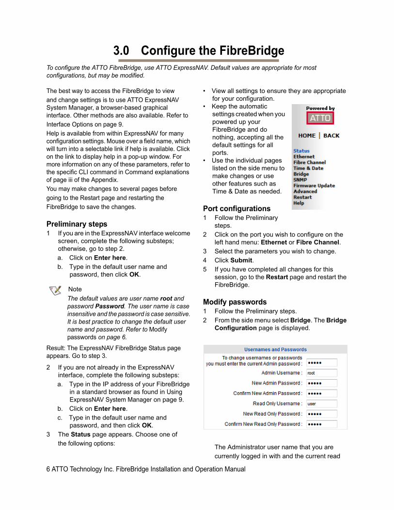
• View all settings to ensure they are appropriate for your configuration.
• Keep the automatic settings created when you powered up your FibreBridge and do nothing, accepting all the default settings for all ports.
• Use the individual pages listed on the side menu to make changes or use other features such as Time & Date as needed.
Port configurations1 Follow the Preliminary
steps.
2 Click on the port you wish to configure on the left hand menu: Ethernet or Fibre Channel.
3 Select the parameters you wish to change.
4 Click Submit.
5 If you have completed all changes for this session, go to the Restart page and restart the FibreBridge.
Modify passwords1 Follow the Preliminary steps.
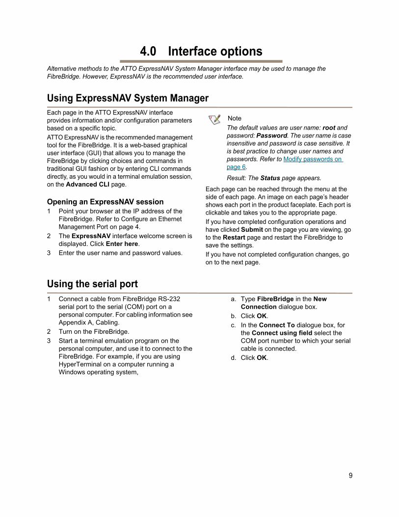
2 From the side menu select Bridge. The Bridge Configuration page is displayed.
The Administrator user name that you are
currently logged in with and the current read
6 ATTO Technology Inc. FibreBridge Installation and Operation Manual

only user name, if present, are displayed in
their text boxes.
3 Enter the Administrator (Admin) password where indicated.
4 Enter appropriate information into the New Admin Password, Confirm New Admin Password or New Read Only Password and Confirm New Read Only Password text boxes.
5 Click Submit.
6 If you have completed all changes for this session, go to the Restart page and restart the FibreBridge.
Set Time & Date1 Follow the Preliminary steps.
2 From the side menu select Time & Date. The Time & Date page is displayed.
3 In the section Manually Set Time/Date, enter the current time and date in the applicable fields, in the format specified.
4 Click Submit.
5 If you have completed changes for the session, go to the Restart page and restart the FibreBridge.
Set SNMP Trap RecipientsThe Simple Network Management Protocol (SNMP) facilitates the exchange of management information between network devices.
1) To get the ATTO MIB’s, you must set up your terminal emulation program (i.e. TeraTerm) to output terminal text to a text file (name it with the extention .MIB). a.Issue the “SNMPdumpMIB” CLI command. This needs to be done for all <TC | SMI | Bridge | Product> MIB’s. b.Open the output file and delete the 1st line (probably “SNMPdumpMIB”) and the last line (probably “Ready.”). Save the files as “ATTO-TC”; “ATTO-SMI”; “ATTO-BRIDGE-MIB”; “ATTO-PRODUCTS-MIB”
An agent residing in the FibreBridge takes information from the FibreBridge and translates it into a format compatible with SNMP. If certain conditions arise, the agent sends asynchronous notifications (traps) to a client.
Note
Consult your network administrator for further assistance with SNMP.
1 If you are not already in the ExpressNAV interface, type the IP address of your FibreBridge in a standard browser as found in Using ExpressNAV System Manager on page 9, click Enter Here, type in your user name and password, and click OK.
2 On the left hand menu, click SNMP. The SNMP page appears.
3 Click on the enabled radio button next to the SNMP heading.
4 Click on the appropriate radio button for SNMP Traps. SNMP Traps are notifications of SNMP events such as port transitions and temperature levels.
5 Enter the IP addresses of those who should receive messages (SNMP trap recipients) in the text boxes on the left.
6 Select the type of message you wish each recipient to receive from the drop down box next to each address.
7 Click Submit
7

Exhibit 3.0-1 Events triggering SNMP notification severity level and explanation.
EventSeverity
LevelExplanation
Temperature InfoThe unit’s internal temperature has increased or decreased to within standard operating ranges.
Temperature WarningThe unit’s internal temperature is at or above the unit’s maximum temperature warning threshold, or it is at or below the unit's minimum temperature warning threshold.
Temperature CriticalThe unit’s internal temperature has increased to or above the maximum operating temperature or decreased to or below the minimum operating temperature.
FC Port Transition
Info Fibre Channel port connectivity state has changed.
SAS Port Transition
Info SAS port connectivity state has changed.
SAS PHY Transition
Info SAS PHY connectivity state has changed.
Throughput InfoThroughput measurement indicates no data bottleneck. Data throughput is measured as aggregate completed I/O's per second on the Fibre Channel interfaces.
Throughput WarningIndicates that the bridge throughput has exceeded the warning threshold established for I/Os per second.
Power Supply Critical A power supply has gone offline.
Power Supply Info An offline power supply has come back online.
8 ATTO Technology Inc. FibreBridge Installation and Operation Manual
4.0 Interface optionsAlternative methods to the ATTO ExpressNAV System Manager interface may be used to manage the FibreBridge. However, ExpressNAV is the recommended user interface.
Using ExpressNAV System ManagerEach page in the ATTO ExpressNAV interface provides information and/or configuration parameters based on a specific topic.
ATTO ExpressNAV is the recommended management tool for the FibreBridge. It is a web-based graphical user interface (GUI) that allows you to manage the FibreBridge by clicking choices and commands in traditional GUI fashion or by entering CLI commands directly, as you would in a terminal emulation session, on the Advanced CLI page.
Opening an ExpressNAV session1 Point your browser at the IP address of the
FibreBridge. Refer to Configure an Ethernet Management Port on page 4.
2 The ExpressNAV interface welcome screen is displayed. Click Enter here.
3 Enter the user name and password values.
Note
The default values are user name: root and password: Password. The user name is case insensitive and password is case sensitive. It is best practice to change user names and passwords. Refer to Modify passwords on page 6.
Result: The Status page appears.
Each page can be reached through the menu at the side of each page. An image on each page’s header shows each port in the product faceplate. Each port is clickable and takes you to the appropriate page.
If you have completed configuration operations and have clicked Submit on the page you are viewing, go to the Restart page and restart the FibreBridge to save the settings.
If you have not completed configuration changes, go on to the next page.
Using the serial port 1 Connect a cable from FibreBridge RS-232
serial port to the serial (COM) port on a personal computer. For cabling information see Appendix A, Cabling.
2 Turn on the FibreBridge.
3 Start a terminal emulation program on the personal computer, and use it to connect to the FibreBridge. For example, if you are using HyperTerminal on a computer running a Windows operating system,
a. Type FibreBridge in the New Connection dialogue box.
b. Click OK.
c. In the Connect To dialogue box, for the Connect using field select the COM port number to which your serial cable is connected.
d. Click OK.
9

e. In the COM Properties dialogue box select the following values:
• Bits per second: 115200
• Data Bits: 8
• Parity: None
• Stop Bits: 1
• Flow Control: None
• Terminal type: ASCII
• Echo: on
f. Click OK.
4 After you connect to the FibreBridge, start-up messages are displayed. These messages are only displayed at start-up. The last line in the start-up message sequence is Ready.
5 In serial port sessions, there is no prompt on the line below the word Ready. Begin typing commands in the blank line where the cursor is resting. No user name or password is required for serial port access.
6 To verify that you have connected successfully, type help after the Ready prompt and press Enter.
• If a list of all available commands does not appear on the screen, review the steps in this section, check the cable, or contact service personnel until the problem is solved.
If you have difficulty using the serial port, verify that you have the correct settings and that your serial cable is less then two meters in length.
Using TelnetUp to three Telnet sessions can be conducted simultaneously. A serial port session can use the CLI while Telnet sessions are open. Whichever session issues the first set CLI command can continue to issue set commands, while the other sessions can only issue get commands or display information. Once a connection is established, refer to CLI provides ASCII-based Interface on page ii of the Appendix.
1 Connect to the FibreBridge from a computer on the same Ethernet network.
2 Start a Telnet session.
Note
There is more than one way to connect to the FibreBridge using a telnet program.Your telnet program may operate differently than in the following instructions.
3 At the telnet prompt, issue the open command where x.x.x.x is the IP address of the FibreBridge Management Port.
telnet > open x.x.x.x
4 If you have to specify a port type, enter the port type “telnet” and the terminal type “vt100”.
port type: telnet
terminal type: vt100
5 Enter the default values for the user name, root, and the password, Password, if you did not set new values in Modify passwords on page 6.
10 ATTO Technology Inc. FibreBridge Installation and Operation Manual

5.0 Update FirmwareThe ATTO FibreBridge has several processors which control the flow of data. The firmware to control these processors can be upgraded in the field. The preferred method is to use the ATTO ExpressNAV System Manager.
The FibreBridge firmware is distributed as a .zbd file available from your Storage Solutions provider. Download the file and note the filename.
Note
There is always a backup image in the FibreBridge, in case the flashing process fails. After updating the firmware, verify the correct program version is executing by viewing the status page and checking the firmware revision number.
Using ExpressNAV1 If you are not already in the ExpressNAV
interface, type the IP address of your FibreBridge in a standard browser as found in Using ExpressNAV System Manager on page 9, click Enter Here, type in your user name and password, and click OK.
2 Click on the Firmware Update menu item on the left-hand side of the page.
3 The Firmware Update page appears. Click Browse to locate the firmware you downloaded earlier.
4 Highlight the file.
5 Click Upload.
6 Wait until a new page is displayed that shows the status of each step of the download.
Result: Upon successful completion of the Flashing Firmware process, a notice will appear at the bottom of the page along with a 'Restart' button.
Note
The firmware update process is not complete until bridge is restarted, which loads and executes the new image.
7 Click the Restart button to load and execute the firmware flashed in step 6 above.
Result: Restarting Firmware page will appear and count down, returning you to the Status page. If the page does not count down or gets stuck, refer to Using ExpressNAV System Manager on page 5, and also ensure that your DHCP server has not changed the IP address of the bridge.
8 It is highly recommended that you repeat the firmware update process so that the backup image is replaced with up-to-date firmware.
Using FTP1 Establish an FTP link to the bridge that is to be
flashed using the Ethernet-attached computer or a computer directly connected to a FibreBridge Management Port.
Note
The FibreBridge does not support passive mode. The FTP connection must be set up for both active mode and binary mode for the transfer to complete.
2 Use the PUT command to download the firmware file to the bridge. For example:
PUT c:\bridge_firmware\FB750100.zbd 3 Once the download is complete, cycle power on
the FibreBridge to implement the new firmware.
Note
It is recommended that you use a stand-alone FTP client rather than a browser-based FTP client for firmware downloads to avoid time-outs and lost connections.
4 It is highly recommended that you repeat the firmware update process so that the backup image is replaced with up-to-date firmware.
11

12 ATTO Technology Inc. FibreBridge Installation and Operation Manual

i
Appendix A CablingUse an Ethernet connection to use the ATTO ExpressNAV System Manager interface. Make sure all cables are anchored securely at both ends with the proper connectors.
Serial port connectionsThe ATTO FibreBridge supports remote service operations over the RS-232 serial port using standard terminal emulation software available with most systems.
Connect a RJ45 to DB-9 serial cable (null modem, see Exhibit A-1) between the ATTO FibreBridge serial port and one of the computer's serial COM ports.
Ethernet connectionsThe 100/1000 BaseT Ethernet ports provide remote monitoring and management using the ATTO ExpressNAV interface.
Since the FibreBridge is set to auto mdix, there is no need for a crossover cable when connecting directly to a computer. The ATTO FibreBridge auto detects the Ethernet speed by default.
Exhibit A-1 Cable Pinouts
Note
Note: ATTO FibreBridge 7500N products are shipped with two 3 meter shielded Ethernet cables. These cables must be used to connect the Ethernet management ports to other Ethernet devices to provide proper EMI (Electro-Magnetic Interference) noise reduction and protection. These cables or equivalent must be used with this product.

Appendix B CLI provides ASCII-based InterfaceThe command line interface (CLI) provides access to the ATTO FibreBridge Services through a set of ASCII commands. CLI commands may be entered from the serial port connection or from the ExpressNAV System Manager Advanced page.
FibreBridge Services provide configuration and monitoring for the FibreBridge. The command line interface (CLI) is a set of ASCII-based commands which perform these tasks.
• CLI commands are context sensitive and generally follow a standard format:
[Get|Set] Command [Parameter1|Parameter2]
followed by the return or enter key• CLI commands are case insensitive: you may
type all upper or all lower case or a mixture. Upper and lower case in this manual and the help screen are for clarification only.
• Commands generally have three types of operation: get, set and immediate.
• The get form returns the value of a parameter or setting and is an informational command.
• Responses to get commands are followed by Ready.
• The set form is an action that changes the value of a parameter or configuration setting. It may require a SaveConfiguration command and a restart of the system before it is implemented. The restart can be accomplished as part of the SaveConfiguration command or by using a separate FirmwareRestart command. A number of set commands may be issued before the SaveConfiguration command.
• Responses to set commands are either an error message or Ready. *. The asterisk indicates you must use a SaveConfiguration command to finalize the set command. SaveConfiguration asks if you want to restart the system or not.
• Set commands which do not require a SaveConfiguration command, defined as Immediate commands, are executed.
• Responses to Immediate commands are either an error message or data results followed by Ready.
Symbols, typefaces and abbreviations used to indicate functions and elements of the command line interface used in this manual.
Command conventions
Symbol Indicates
[ ] Required entry
< > Optional entry
| pick one of
… Ellipses, repetition of preceding item
- a range (6 – 9 = 6, 7, 8, 9)
fp Fibre Channel port number (1 or 2)
mp Ethernet port used to manage the FibreBridge (mp1 or mp2)
SASconn SAS connector ID (A, B, C or D)
IP address IPv4 or IPv6 address
ii ATTO Technology Inc. FibreBridge Installation and Operation Manual

CLI error messagesThe following error messages may be returned by the Command line Interface
ERROR. Invalid Command. Type 'Help' for command list.
ERROR. Wrong/Missing Parameters
Usage: <usage string>
ERROR. Command Not Processed
CLI summary referenceA summary of the Command Line Interface commands and their defaults is given below. Only those commands which have a "set" component that can be stored in non-volatile memory have a default listed. Commands which have no default values associated with them have a blank entry in that column of the table. Commands which are not present in the specified unit list "N/A" in that column.
Command Default Example
BridgeModel get bridgemodel
BridgeName “ “ set bridgename Omega6
ClearEventLog cleareventlog
CoreDumpInfo coredumpinfo
Date 01/01/2000 set date 03/03/03
DumpConfiguration dumpconfiguration
DumpEventLog dumpeventlog
EthernetSpeed auto set ethernetspeed 100
Exit exit
FCConnMode PTP-LOOP set fcconnmode all ptp
FCDataRate auto get fcdatarate 1
FCPortDisable fcportdisable 1
FCPortEnable fcportenable 2
FCPortErrors get fcporterrors all
FCPortList fcportlist
FCPortReset fcportreset 1
FCSFPInfo get fcsfpinfo 2
FCWWName get fcwwname 1
FirmwareRestart firmwarerestart
FlashImages flashimages
Help help SAS Targets
IdentifyBridge disabled set identifybridge enabled
Info info
IPAddress 10.0.0.1 get ipaddress mp1
IPDHCP enabled set ipdhcp mp1 disabled
IPDNSServer 0.0.0.0 get ipdnsserver
iii

Command explanations
BridgeModelReports model and firmware information about the FibreBridge.
get BridgeModel
BridgeNameSpecifies the 32-character ASCII name assigned to the FibreBridge used to identify individual units. It is not the World Wide Name. The string is alphanumeric and can be up to 32 characters long. If the name contains spaces, it must be enclosed in quotation marks. Changes take effect immediately.
Default: “ “set BridgeName [name]get BridgeName
IPGateway 0.0.0.0 set ipgateway mp1 200.10.22.3
IPSubnetMask 255.255.0.0 get ipsubnetmask mp1
IPV6Prefix set IPV6Prefix all 32
Password Password set password
Ping ping mp1 192.42.155.155
ReadOnlyPassword Password get readonlypassword
ReadOnlyUsername user get readonlyusername
ResetFCPortErrors resetfcporterrors 1
RouteDisplay RouteDisplay FC
SASConnectorInfo get sasconnectorinfo all
SASPortDisable sasportdisable a
SASPortEnable sasportenable b
SASPortList sasportlist
SASPortReset sasportreset c
SASTargets sastargets
SaveConfiguration saveconfiguration restart
SerialNumber get serialnumber
SerialPortBaudRate 115200 set serialportbaudrate 19200
SNMP enabled set SNMP disabled
SNMPDumpMIB SNMPDumpMIB Bridge
SNMPTrapAddress 0.0.0.0 none set snmptrapaddress 6 192.42.155.155 all
SNMPTraps enabled set snmptraps enabled
SNTP enabled get sntp
SNTPServer 192.43.244.18 set sntpserver 129.6.15.28
Temperature get temperature
Time 00:00:00 set time 03:32:30
TimeZone EST set timezone pst
Uptime nothing Uptime
Username root set username Barbara
Command Default Example
iv ATTO Technology Inc. FibreBridge Installation and Operation Manual
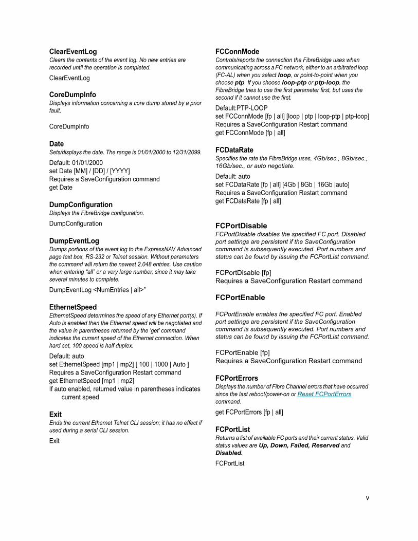
ClearEventLogClears the contents of the event log. No new entries are recorded until the operation is completed.
ClearEventLog
CoreDumpInfoDisplays information concerning a core dump stored by a prior fault.
CoreDumpInfo
DateSets/displays the date. The range is 01/01/2000 to 12/31/2099.
Default: 01/01/2000set Date [MM] / [DD] / [YYYY]Requires a SaveConfiguration commandget Date
DumpConfigurationDisplays the FibreBridge configuration.
DumpConfiguration
DumpEventLog Dumps portions of the event log to the ExpressNAV Advanced page text box, RS-232 or Telnet session. Without parameters the command will return the newest 2,048 entries. Use caution when entering “all” or a very large number, since it may take several minutes to complete.
DumpEventLog <NumEntries | all>”
EthernetSpeedEthernetSpeed determines the speed of any Ethernet port(s). If Auto is enabled then the Ethernet speed will be negotiated and the value in parentheses returned by the 'get' command indicates the current speed of the Ethernet connection. When hard set, 100 speed is half duplex.
Default: autoset EthernetSpeed [mp1 | mp2] [ 100 | 1000 | Auto ]Requires a SaveConfiguration Restart commandget EthernetSpeed [mp1 | mp2] If auto enabled, returned value in parentheses indicates
current speed
ExitEnds the current Ethernet Telnet CLI session; it has no effect if used during a serial CLI session.
Exit
FCConnMode Controls/reports the connection the FibreBridge uses when communicating across a FC network, either to an arbitrated loop (FC-AL) when you select loop, or point-to-point when you choose ptp. If you choose loop-ptp or ptp-loop, the FibreBridge tries to use the first parameter first, but uses the second if it cannot use the first.
Default:PTP-LOOPset FCConnMode [fp | all] [loop | ptp | loop-ptp | ptp-loop]Requires a SaveConfiguration Restart commandget FCConnMode [fp | all]
FCDataRateSpecifies the rate the FibreBridge uses, 4Gb/sec., 8Gb/sec., 16Gb/sec., or auto negotiate.
Default: autoset FCDataRate [fp | all] [4Gb | 8Gb | 16Gb |auto]Requires a SaveConfiguration Restart commandget FCDataRate [fp | all]
FCPortDisableFCPortDisable disables the specified FC port. Disabled port settings are persistent if the SaveConfiguration command is subsequently executed. Port numbers and status can be found by issuing the FCPortList command.
FCPortDisable [fp]Requires a SaveConfiguration Restart command
FCPortEnable
FCPortEnable enables the specified FC port. Enabled port settings are persistent if the SaveConfiguration command is subsequently executed. Port numbers and status can be found by issuing the FCPortList command.
FCPortEnable [fp]Requires a SaveConfiguration Restart command
FCPortErrorsDisplays the number of Fibre Channel errors that have occurred since the last reboot/power-on or Reset FCPortErrors command.
get FCPortErrors [fp | all]
FCPortListReturns a list of available FC ports and their current status. Valid status values are Up, Down, Failed, Reserved and Disabled.
FCPortList
v
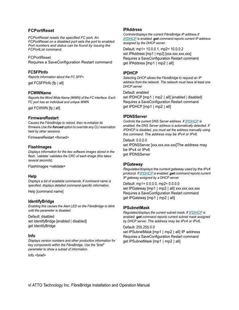
FCPortReset
FCPortReset resets the specified FC port. An FCPortReset on a disabled port sets the port to enabled. Port numbers and status can be found by issuing the FCPortList command.
FCPortResetRequires a SaveConfiguration Restart command
FCSFPInfoReports information about the FC SFP+.
get FCSFPInfo [fp | all]
FCWWName Reports the Word Wide Name (WWN) of the FC interface. Each FC port has an individual and unique WWN.
get FCWWN [fp | all]
FirmwareRestartCauses the FibreBridge to reboot, then re-initialize its firmware.Use the forced option to override any CLI reservation held by other sessions.
FirmwareRestart <forced>
FlashImagesDisplays information for the two software images stored in the flash. ‘validate’ validates the CRC of each image (this takes several seconds).
FlashImages <validate>
HelpDisplays a list of available commands. If command name is specified, displays detailed command-specific information.
Help [command name]
IdentifyBridgeEnabling this causes the Alert LED on the FibreBridge to blink until the parameter is disabled.
Default: disabledset IdentifyBridge [enabled | disabled]get IdentifyBridge
InfoDisplays version numbers and other production information for key components within the FibreBridge. Use the “brief” parameter to show a subset of information.
Info <brief>
IPAddressControls/displays the current FibreBridge IP address.If IPDHCP is enabled, get command reports current IP address assigned by the DHCP server.
Default: mp1= 10.0.0.1, mp2= 10.0.0.2set IPAddress [mp1 | mp2] [xxx.xxx.xxx.xxx]Requires a SaveConfiguration Restart commandget IPAddress [mp1 | mp2 | all]
IPDHCPSelecting DHCP allows the FibreBridge to request an IP address from the network. The network must have at least one DHCP server.
Default: enabledset IPDHCP [mp1 | mp2 | all] [enabled | disabled]Requires a SaveConfiguration Restart commandget IPDHCP [mp1 | mp2 | all]
IPDNSServerControls the current DNS Server address. If IPDHCP is enabled, the DNS Server address is automatically detected. If IPDHCP is disabled, you must set the address manually using this command. The address may be IPv4 or IPv6.
Default: 0.0.0.0set IPDNSServer [xxx.xxx.xxx.xxx]The address may be IPv4 or IPv6get IPDNSServer
IPGatewayRegulates/displays the current gateway used by the IPv4 protocol. If IPDHCP is enabled, get command reports current IP gateway assigned by a DHCP server.
Default: mp1= 0.0.0.0, mp2= 0.0.0.0set IPGateway [mp1 | mp2 | all] xxx.xxx.xxx.xxxRequires a SaveConfiguration Restart commandget IPGateway [mp1 | mp2 | all]
IPSubnetMaskRegulates/displays the current subnet mask. If IPDHCP is enabled, get command reports current subnet mask assigned by DHCP server. The address may be IPv4 or IPv6.
Default: 255.255.0.0set IPSubnetMask [mp1 | mp2 | all] IP addressRequires a SaveConfiguration Restart commandget IPSubnetMask [mp1 | mp2 | all]
vi ATTO Technology Inc. FibreBridge Installation and Operation Manual

IPV6PrefixIPV6Prefix controls the current IPV6 prefix length of any Ethernet port(s).
Default: Noneset IPV6Prefix [mp1 | mp2 | all] [Prefix length]Requires a SaveConfiguration Restart commandget IPV6Prefix [mp1 | mp2 | all]
PasswordSpecifies password for all non-serial sessions: Telnet, FTP and ExpressNAV interface. You are prompted for the current password, to enter the new password, and to confirm the new password. When the password is all 0s, Telnet and FTP do not validate the password and MD5 authentication is disabled.Configure an empty password by pressing the Enter key when prompted for the new password and the new password confirmation.Passwords are case sensitive and can be 1-32 characters long with no spaces.
Default: Passwordset Password Requires a SaveConfiguration command
PingSends an ICMP echo request to the specified host.
Ping [mp1 | mp2] [IP address] <count <size>>
ReadOnlyPasswordSpecifies read only password for all non-serial sessions: Telnet, FTP and ExpressNAV interface. ReadOnlyPassword is case sensitive, 0 to 32 characters, and cannot contain spaces.
Default: Passwordset ReadOnlyPassword Requires a SaveConfiguration command
ReadOnlyUsername Specifies read only user name for Telnet and ExpressNAV user management console sessions. Username is case insensitive, 1-32 characters, no spaces.
Default: Userset ReadOnlyUsername Requires a SaveConfiguration commandget ReadOnlyUsername
Reset FCPortErrorsResets all FC error counts for the specified port to zero. Refer to FCPortErrors command.
ResetFCPortErrors [fp | all]
RouteDisplay Displays a list of Fibre Channel to target device address mappings on the FibreBridge.
RouteDisplay FC
SASConnectorInfoSASConnectorInfo displays information about the specified SAS connector. Valid connector names are A through D.
get SASConnectorInfo [sasConn | all]
SASPortDisable SASPortDisable disables all 4 PHYs of the specified SAS port (connector). Port IDs and status can be found by issuing the SASPortList command.
SASPortDisable [sasConn]Requires a SaveConfiguration Restart command
SASPortEnable SASPortEnable enables all 4 PHYs of the specified SAS port (connector).Port IDs and status can be found by issuing the SASPortList command.
SASPortEnable [sasConn]Requires a SaveConfiguration Restart command
SASPortListLists the status of all SAS ports.
SASPortList
SASPortReset SASPortReset resets all 4 PHYs of the specified SAS port (connector). A SASPortReset on a disabled port sets the port to enabled. Port IDs and status can be found by issuing the SASPortList command.
SASPortReset [sasConn]
SASTargetsLists the physical devices that are connected to all SAS connectors and PHYs.
SASTargets
SaveConfigurationMany commands require a SaveConfiguration command to be executed as indicated by the return Ready. *. When you invoke a SaveConfiguration command, the current configuration is permanently saved in the FibreBridge and the new configuration becomes the active configuration. If a firmware restart is required to make the requested change permanent, you are asked to confirm the restart. You can override this request by indicating the override value on the
vii
command line. You may make several changes through commands before implementing the restart, but once you have restarted the FibreBridge, all the command changes created before the restart and save are implemented. If you select the restart option, the FibreBridge executes its complete start up cycle.
SaveConfiguration <Restart | NoRestart>
SerialNumberReports the FibreBridge serial number. The serial number, unique for each FibreBridge, is a 13-character field. The first seven alphanumeric characters are an abbreviation of the product name while the remaining six numbers are the individual FibreBridge board’s number.
get SerialNumber
SerialPortBaudRateConfigures/reports the baud rate for the FibreBridge RS-232serial port or header. The number of data bits per character isfixed at 8 with no parity.
Default: 115200set SerialPortBaudRate [9600 | 19200 | 38400 | 57600 | 115200]Requires a SaveConfiguration Restart commandget SerialPortBaudRate
SNMPControls whether or not SNMP functions on the FibreBridge.
Default: enabledset SNMP [enabled | disabled]Requires a SaveConfiguration Restart commandget SNMP
SNMPDumpMIBDisplays the contents of the ATTO FibreBridge private SNMP MIB to the current CLI session. Consult your network administrator for further assistance with SNMP.
SNMPDumpMIB <TC | SMI | Bridge | Product>
SNMPTrapAddressSets/displays the IP trap addresses and levels.Consult your network administrator for further assistance with SNMP.
Default: 0.0.0.0 noneset SNMPTrapAddress [Index] [IPAddress] [None | All | Warning | Critical ]Requires a SaveConfiguration commandget SNMPTrapAddress [index | all]Index: value between 1 and 6IPAddress: standard IP address for the host receiving messagesTrap Level: severity required for an event to trigger a trap:None: no traps are sent to the addressALL: all triggering events are sentWarning: warning and critical events are sentCritical: only critical events trigger a trap
SNMPTrapsControls SNMP trap functions.Consult your network administrator for further assistance with SNMP.
Default: enabledset SNMPTraps [enabled | disabled]Requires a SaveConfiguration commandget SNMPTraps
SNTPControls whether the FibreBridge contacts a specified SNTP time server to initialize or synchronize the time.
Default: enabledset SNTP [enabled | disabled]Requires a SaveConfiguration Restart commandget SNTP
SNTPServerControls/displays the main IP address of the SNTP time server. If the FibreBridge is unable to contact the specified SNTP time server within 30 seconds, the FibreBridge tries to contact the first auxiliary SNTP time server. If not successful, the FibreBridge tries to contact the second auxiliary server. If not successful, the FibreBridge continues to keep time based on the most recent SNTP time server, physical RTC or manual initialization or synchronization.
Default: 192.43.244.18set SNTPServer [IP address]Requires a SaveConfiguration Restart commandget SNTPServer
TemperatureDisplays the current internal temperature of the FibreBridge in degrees Celsius.
get Temperature
viii ATTO Technology Inc. FibreBridge Installation and Operation Manual

TimeControls/displays the time in a 24-hour format. The default time is 00:00:00 and is accurate until the FibreBridge is reset or power-cycled when it returns to the default.Time cannot be set if SNTP is enabled.
Default: 0:00:00set Time [HH :MM :SS]Requires a SaveConfiguration commandget Time
TimeZoneControls/displays the time zone. Setting may be EST, CST, MST PST or a numerical offset from GMT in the format +/- HH:MM. When SNTP is enabled, applies the time zone setting to the time retrieved from a specified SNTP time server to determine local time.
Default: ESTset TimeZone [EST | CST | MST | PST | [+ / - HH : MM]]Requires a SaveConfiguration commandget TimeZone
UptimeReturns the time [days hrs:min:sec] since the last FibreBridge reboot.
Uptime
UsernameSpecifies user name for all Telnet, FTP and ExpressNAV user management console sessions. Username is case insensitive, 1-32 characters, no spaces.
Default: rootset Username Requires a SaveConfiguration commandget Username
ix

Appendix C Standards and CompliancesThe equipment described in this manual generates and uses radio frequency energy. If this equipment is not used in strict accordance with the manufacturer’s instruction, it can and may cause interference with radio and television reception.
Regulatory Notices
Bureau of Standards, Metrology, and Inspections Notice (BSMI, Taiwan Only)
Translation of this BSMI notice: Warning: This is a Class A product. In a domestic environment this product may cause radio interference, in which case the user may be required to take adequate measures.
Voluntary Control Council for Interference by Information Technology Equipment (VCCI, Japan)
Translation of the VCCI-A notice: This is a Class A product based on the standard of the Voluntary Control Council for Interference by Information Technology Equipment (VCCI). If this equipment is used in a domestic environment, radio disturbance may arise. If such trouble occurs, the user may be required to take corrective actions.
Compliance Statement, Korea
Translation of Korean Compliance Statement: This is a Class A device and is registered for EMC requirements for industrial use. The seller or buyer should be aware of this. If this type was sold or purchased by mistake, it should be replaced with a residential-use type.
xi

The product has been certified and bears the Mark, as applicable, of the EMC and Product Safety authorities as indicated below:
Safety: TUV 72141224, EN 60950, CE, CSA 60950, UL 60950, CB IEC60950-1 (all national deviations)Emissions/Immunity: FCC Part 15 Class A, ICES-003, CE-EN55032, EN55024, IEC61000-3-2, IEC61000-3-3, KN22/KN24, VCCI, AS/NZS, BSMIMarks/Certificates: cTUVus, CE, SABS, SONCAP, IRAM, KCC, BSMI, RCM, EAC, Ukr-Sepro, KSA-SASO
FCC Notices (US only)
This equipment has been tested and found to comply with the limits for Class A digital devices,pursuant to Part 15 of the FCC Rules. These limits are designed to provide reasonable protectionagainst harmful interference when the equipment is operated in a commercial environment. Thisequipment generates, uses, and can radiate radio frequency energy and, if not installed and used inaccordance with the instruction manual, may cause harmful interference to radio communications.Operation of this equipment in a residential area is likely to cause harmful interference in which casethe user will be required to correct the interference at his own expense.
Compliance with ICES-003This Class A digital apparatus complies with Canadian ICES-003.Cet appareil numérique de la classe A conforme à la norme NMB-003 du Canada.
Compliance with EN RegulationsMarking by the symbol indicates compliance of this ATTO device to the EMC Directive and the LowVoltage Directive of the European Union.
The ATTO FibreBridge 7500N complies with Directive 2011/65/EC on the Restriction of the Use of Hazardous Substances in Electrical and Electronic Equipment RoHS2 (recast) and take the following exemptions:
6(c)- Copper allot containing up to 4% lead by weight.
7(a) -Lead in high melting temperature type solders (i.e. lead based alloys containing 85% by weight or more lead).
7(c)-l -Electrical and electronic components containing lead in a glass or ceramic other than dielectric ceramic in capacitors, e.g. piezoelectronic devices, or in glass or ceramic matrix compound.
13(a) - Lead in white glasses used for optical applications.
15 - Lead in solders to complete a viable electrical connection between semiconductor die and carrier within integrated circuit flip chip packages.
xii ATTO Technology Inc. FibreBridge Installation and Operation Manual

xi
Appendix D Warranty Information
ATTO Technology, Inc. limited warrantyATTO Technology, Inc. (“ATTO”) warrants to the original purchaser of this product (“Product”) that the Product is free from defects in material and workmanship for the term described for this specific Product on ATTO's website (www.attotech.com). ATTO's liability shall be limited to replacing or repairing any defective product at ATTO's option. There is no charge for parts or labor if ATTO determines that this product is defective.
PRODUCTS WHICH HAVE BEEN SUBJECT TO ABUSE, MISUSE, ALTERATION, NEGLECT, OR THOSE PRODUCTS THAT HAVE BEEN SERVICED, REPAIRED OR INSTALLED BY UNAUTHORIZED PERSONNEL WILL NOT BE COVERED UNDER THIS WARRANTY. DAMAGE RESULTING FROM INCORRECT CONNECTION OR AN INAPPROPRIATE APPLICATION OF THIS PRODUCT SHALL NOT BE THE RESPONSIBILITY OF ATTO. LIABILITY UNDER THIS LIMITED WARRANTY IS LIMITED TO ATTO PRODUCT(S). DAMAGE TO OTHER EQUIPMENT CONNECTED TO ATTO PRODUCT(S) IS THE CUSTOMER'S RESPONSIBILITY. THIS LIMITED WARRANTY IS MADE IN LIEU OF ANY OTHER WARRANTIES, EXPRESS OR IMPLIED. ATTO DISCLAIMS ANY IMPLIED WARRANTIES OF MERCHANTABILITY OR FITNESS FOR A PARTICULAR PURPOSE TO THE EXTENT IMPLIED WARRANTIES CANNOT BE EXCLUDED, SUCH IMPLIED WARRANTIES ARE LIMITED IN DURATION TO THE EXPRESS WARRANTY PERIOD APPLICABLE TO THE PRODUCT. BECAUSE SOME STATES OR JURISDICTIONS DO NOT ALLOW LIMITATIONS ON THE DURATION OF IMPLIED WARRANTIES, THE ABOVE MAY NOT BE APPLICABLE. ATTO'S RESPONSIBILITY TO REPAIR OR REPLACE A DEFECTIVE PRODUCT IS THE SOLE AND EXCLUSIVE REMEDY PROVIDED TO THE CUSTOMER FOR BREACH OF THIS WARRANTY.
ATTO IS NOT RESPONSIBLE FOR DAMAGE TO OR LOSS OF ANY DATA, PROGRAMS OR ANY MEDIA. THE PRODUCTS ARE NOT INTENDED FOR USE IN: (I) MEDICAL DEVICES OR THE MEDICAL FIELD; OR (II) USE IN RUGGED APPLICATIONS.
ATTO IS NOT LIABLE FOR ANY INDIRECT, SPECIAL, INCIDENTAL, OR CONSEQUENTIAL DAMAGES, IRRESPECTIVE OF WHETHER ATTO HAS BEEN ADVISED OF THE POSSIBILITY OF SUCH DAMAGES. NO ATTO DEALER, AGENT OR EMPLOYEE IS AUTHORIZED TO MAKE ANY MODIFICATION, EXTENSION OR ADDITION TO THIS WARRANTY.
This warranty gives you specific legal rights, and you may also have other rights which vary from state to state.