attachments System Troubleshooting Check Sheet - US07 ...
47
9/2/2020 Content creation stages KC-663 https://volvo-trkna-prod1.pegacloud.net/prweb/PRAuth/iNPUIKpeinqPJi2G0hH930k43USdE1gb*/!TABTHREAD13?pyActivity=%40baseclass.pzProces… 1/2 Emcon (Spark Assist) Engine Aftertreatment System Troubleshooting Check Sheet - US07 Emissions It has been found that on these older chassis it is best to eliminate all the basics prior to opening an eService case. Pressure test the complete intake and exhaust systems. There is zero tolerance for leaks in these systems. Next, go over all the wiring harnesses to see if there are crispy spots No rub spots, loose areas are tolerated. Next check the chassis air supply system to be sure the customer has been draining the air tanks nightly and servicing the air dryer every 6 months with a fresh COALESCING type air dryer cartridge. This DPF system cannot tolerate ANY water or oil moisture at all for it to function correctly and reliably. Repair any leaks, electrical and air system issues before starting to dig into the Aftertreatment system. Use the US07 Spark Assist Check Sheet (Click to open) to compare sensor and component values during fault tracing for spark assisted regeneration troubleshooting. Please refer to the reference documentation below. • TRU Regen Design and Function • EMCON System Training Overview Tags K25470463 SPARK ASSIST CHECKLIST CHECK SHEET CHECK LIST Related links and attachments US07 SYMPTOM BASED CHECK SHEET W2034.3 US07 EMCON TRAINING_System Overview US07 TRU Regeneration DESIGN AND FUNCTION_W1730.7 Internal Content : a
Transcript of attachments System Troubleshooting Check Sheet - US07 ...

9/2/2020 Content creation stages KC-663
https://volvo-trkna-prod1.pegacloud.net/prweb/PRAuth/iNPUIKpeinqPJi2G0hH930k43USdE1gb*/!TABTHREAD13?pyActivity=%40baseclass.pzProces… 1/2
Emcon (Spark Assist) Engine AftertreatmentSystem Troubleshooting Check Sheet - US07Emissions
It has been found that on these older chassis it is best to eliminate all thebasics prior to opening an eService case. Pressure test the completeintake and exhaust systems. There is zero tolerance for leaks in thesesystems. Next, go over all the wiring harnesses to see if there are crispyspots No rub spots, loose areas are tolerated. Next check the chassis airsupply system to be sure the customer has been draining the air tanksnightly and servicing the air dryer every 6 months with a freshCOALESCING type air dryer cartridge. This DPF system cannot tolerateANY water or oil moisture at all for it to function correctly and reliably.Repair any leaks, electrical and air system issues before starting to diginto the Aftertreatment system.
Use the US07 Spark Assist Check Sheet (Click to open) to comparesensor and component values during fault tracing for spark assistedregeneration troubleshooting.
Please refer to the reference documentation below.
• TRU Regen Design and Function
• EMCON System Training Overview
Tags
K25470463 SPARK ASSIST CHECKLIST
CHECK SHEET CHECK LIST
Related links andattachmentsUS07 SYMPTOM BASEDCHECK SHEET W2034.3
US07 EMCONTRAINING_SystemOverview
US07 TRU RegenerationDESIGN ANDFUNCTION_W1730.7
Internal Content:
a

9/2/2020 Content creation stages KC-663
https://volvo-trkna-prod1.pegacloud.net/prweb/PRAuth/iNPUIKpeinqPJi2G0hH930k43USdE1gb*/!TABTHREAD13?pyActivity=%40baseclass.pzProces… 2/2
Feedback
Give feedback to help improve the content of this article

DPF Regeneration Companion Sheet (SPN4094 v1730.7)
Spark Assist (Mack only US07)
Before starting diagnosing Regen issues with this system, a thorough investigation of the condition of the complete chassis needs to be done.
• Has the Chassis Air System been serviced correctly base on published service information? If not, correct the issues. The air dryer needs to be properly connected and the filter serviced with a recommended Coalescent cartridge. The pressure in the system needs to be regulated within the correct tolerances. If the dryer system comes in by-passed or inoperative, the air tanks and lines supplying the aftertreatment system may need to be cleaned out. Otherwise, the Air Atomization Module (even a new replacement) will not last at all.
• Has the fuel system been serviced correctly based on published service information? If not, inform the operator that the fuel system needs to be serviced.
• Is the engine air filter flowing correctly and not plugged? If not, inform the operator that the filter needs to be serviced.
Combustion Air Flow. 400+ LPM is required during Regen with idle set to 700 RPM for US07.
• US07 - The CAV has an arrow on it to show direction of flow. The orifice in the intake manifold should be 3/8”. There should be NO orifice at all in the CAV fitting boss at the combustor housing.
o There have been reported instances of replacement US07 combustor housings that had the US10 9/32”orifices in place at the Combustion Air inlet port of the Combustor Housing. Inspect new replacement Combustor Housings for an orifice.
Typically, the Spark Assist system will complete a Service Regen even when there is NO combustion air flow. It will only display Flame Temp readings of only around 1700*F where proper flame temperature is normally at 1850 – 2100*F. There is typically enough oxygen remaining in the exhaust stream to support combustion under Service Regeneration conditions. This has fooled many in the past giving the impression of successful Regens but when under load, on the road, the oxygen from the engine is all used up by the engine combustion process and Regens will fail under load. So it needs Combustion Air under these conditions to support successful combustion.
Note that any leaks in the intake or exhaust systems will cause issues. The best way to inspect for and diagnose leaks is with the smoke test machine. Repair all leaks before proceeding.

Air Atomization Module (AAM) flow chart
Fuel Supply System
100 PSI fuel pressure Nominal. Range is 95 to 105. 95 psi is at the extreme low limit. 94 or less will give you reliability issues. The fuel pressure is controlled by the Atomization Module (AAM) and not the pump.
o If fuel pressure is low, remove the fuel return line from the AAM to the fuel tank and look for the amount of return with the engine running and pump active. Remove the AAM return line at the fuel tank return tee and cap the tee.
o LOW fuel pressure – LOW return flow indicates a bad pump or restriction from the engine supply to the pump inlet.
o LOW fuel pressure – HIGH return flow indicates the pressure control valve in the AAM is stuck open.
o Another indication of the Atomization Module dumping fuel on the US07 engine platform, is in engine pressure sensor values during a Regen, fuel pressure lower than 40 psi, engine load higher than 15% and slightly lower boost pressure. These are indications of fuel starvation. This is more important on the US07 engine platform because the Atomization Modules in this platform do not have pressure sensors and the Regens are done at idle.
o Note: In some cases, drops in engine power have been reported when the system goes into auto Regens while driving. In most of these cases, the issue is engine fuel

starvation due to the Atomization Module pressure control valve stuck open and dumping fuel pressure. The engine fuel pump cannot keep up with the engine and DPF fuel demand with this condition, and the fuel pressure drops.
o HIGH fuel pressure – LOW flow indicates a blockage in the Atomization Module or the return line. Test the return flow again at the return fitting at the Atomization Module this time. If flow returns to normal, the issue is a blocked return line. If the flow remains low with high fuel pressure, the issues is a blockage within the Atomization Module.
Air Supply System
120 PSI air system air pressure to the AAM Nominal. 100 to 130 PSI is acceptable.
o Less than 100 PSI will cause issues. Pressures over 135 will cause issues. If the pressure is OK stationary (no Regen), and drops during Regen, there is a restriction in one of the lines, or a sticking pressure protection/supply valve, or a valve installed incorrectly, or the air supply was modified by the body builder (we have seen air taken from the wrong tank). The air system actually does not take all that much air. Atomization air is restricted through the orifices in the nozzle and the flow should decrease as fuel is injected (sharing the same holes).
o On the US07 system the Supplemental Air Valve should only activate momentarily on the initial system test ( 1 or 2 seconds ) then remain off for a Service Regen.
o When checking the fuel spray pattern at the nozzle, with Atomization Valve active and Injector control active, you should have a heavy white fog. Not a stream of fuel and not a light mist.
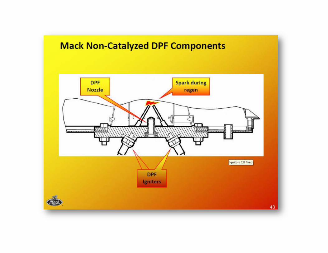
Spark Ignition System
o When checking for spark quality, it should be checked during an active Regen command, not with the Tech Tool test. For some reason, when tested with the Tech Tool, the pulse rate is lower (longer coil charge time) than it is during an active Regen. A good test tool to have handy is a straight in-line spark tester (the style with the light bulb and not the open gap type). Auto parts supply stores typically sell these for about $7.00.
General Electrical
o On the US07 system, it is recommended to monitor the Emcon module Battery and Ignition voltage during the system test period when all components are turned on and again during an active Regen.
o There should be no voltage drop at all compared to the battery voltage. The wires from fuses 54 and 64 are adequate but marginal and it does not take much of a resistance problem in the wires to cause Regen issues.
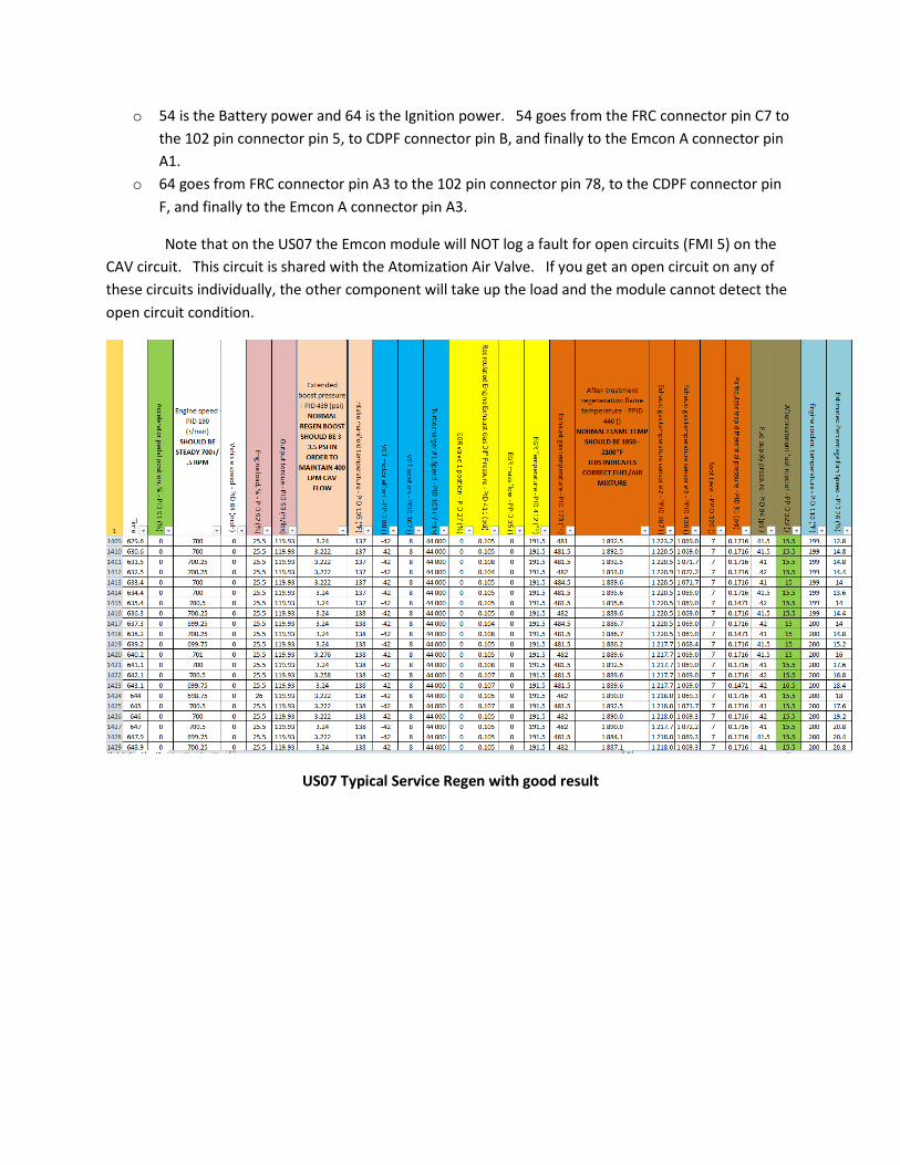
o 54 is the Battery power and 64 is the Ignition power. 54 goes from the FRC connector pin C7 to the 102 pin connector pin 5, to CDPF connector pin B, and finally to the Emcon A connector pin A1.
o 64 goes from FRC connector pin A3 to the 102 pin connector pin 78, to the CDPF connector pin F, and finally to the Emcon A connector pin A3.
Note that on the US07 the Emcon module will NOT log a fault for open circuits (FMI 5) on the CAV circuit. This circuit is shared with the Atomization Air Valve. If you get an open circuit on any of these circuits individually, the other component will take up the load and the module cannot detect the open circuit condition.
US07 Typical Service Regen with good result

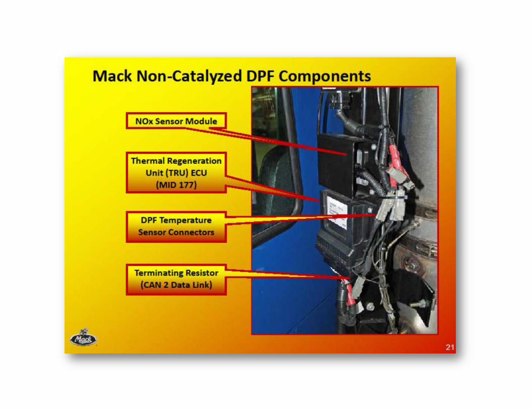
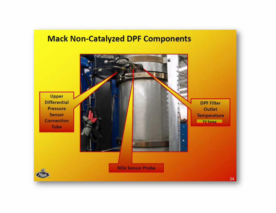
System Overview


T1 Temp
Flame T
T2 Temp
T3 Temp

T1 Temp
Flame T
T2 Temp
T3 Temp
T1
T2
T3
Flame


T2 Temp
T3 Temp


CHASSIS MODEL AND SERIAL NUMBER
1 SMART SWITCH INHIBITTED? Y N
2 FAULT CODES LOGGED MID PID SID PPID PSID FMI
CLEAR ALL FAULTS AND CONTINUE
3 IDLE SPEED SET TO? RPM
4 MID 177 SW PART NUMBER 21429010 OR HIGHER? Y N
5 All Air Tanks drained? Y N
6 Was there any signs of water or oil? Y N
7 Is the correct COALESCING Air Dryer intalled? Y N BRAND PART #
8 When was the air dryer last serviced?
9 DP SENSOR HOSES PER SB 234-020? Y N10 TEMP SENSORS CORRECTLY INSTALLED Y N
CASE NUMBER
OCCURRENCES
If the MID177 cannot be read J1587 wire may be removed per FSB258-011
US07 EMCON -- FAILED REGEN CHECK SHEET (W2034.3)
SHOULD BE SET TO 700 RPM
mm / dd / yyy
GUIDED DIAGNOSTICS SYMPTOM-BASED DIAGNOSIS FOR THE FOLLOWING STEPS

11Combustion Air Valve CORRECTLY ORIENTED AND NO LOOSE FITTINGS OR CONNECTOR - Coil on valve mounted tightly? OK NOK
12 CAV FLOW with engine running with Regen activated and CAV activated LPM
13 CAV FLOW with the outlet of the toot to ATMOSPHERE
LPM
14SPARK OBERVED IN NOZZLE HOLE (circle one) STEADY NONE
15
IF NO SPARK OR NOT STEADY - REMOVE 1 SPARK PLUG WIRE FROM THE COIL, INSTALL AN IN-LINE SPARK TESTER BETWEEN THE COIL AND THE
WIRE AND TEST AGAIN TO SEE IF THE BULB LIGHTS UP
STEADY NONE
16 FUEL LINES CORRECTLY INSTALLED? Y N17 FUEL PRESSURE INTO THE ATOMIZATION MODULE PSI
NONE A LITTLE A LOT( If NONE ) FUEL PRESSURE INTO FUEL SHUT OFF PSI( If only supply pressure ) VOLTS AT FUEL PUMP/VALVE VOLTS
18 FUEL SPRAY PATTERN (CHECK ONE) FUEL STREAMNO FUELWHITE FOG
19 AIR PRESSURE INTO THE ATOMIZATION MODULE PSI20 FUEL NOZZLE AIR PRESSURE PSI KEY OFF
PSINOTE: over 12 psi requires nozzle replacement
PSI
21 DPF DP READING KEY ON - ENGINE OFF PSI22 DPF DP READING AT IDLE PSI23 DPF DP READING AT HIGH IDLE PSI24 DPF DP READING UNDER HARD ACCEL PSI25 FLAME TEMP DURING SERVICE REGEN DEGREES F26 BOOST PRESSURE DURING SERVICE REGEN PSI
KEY ON - ENGINE RUNNING - MASTER AIR VALVE & CAV ON
KEY ON - ENGINE RUNNING (master air valve on)
INTERMITTENT
If fuel pressure is lower than min spec in GD (95 psi) - how much fuel is returning to the tank from the Atomization Module?
Per GD instructions
READ THE SCRIBE LINE IN THE MIDDLE OF THE BOBBER
Note: CAV and Atomization valve open with the same button
See FSB258-011 but do NOT activate the coil with the wires removed INTERMITTENT
TOOL PART NUMBER 85112577
DWYER VFC-132-EC CAN BE SUBSTITUTED
Engine Running - Regen Activated - Fuel Valve and Pump Active
FSB258-012
Note: During active Regen, Nozzle pressure should be around 60 psi

27 EGR DIFF. PRESS. KEY - ON ENGINE OFF PSI
28WITH INLET PIPE OFF OR FILTER REMOVED
SMOKE LEVEL TRANS IN GEAR - OPERATING ARM (CIRCLE ONE)
SLIGHT HAZE
SOME BLACK
FREIGHT TRAINBLACK
DIAGNOSTICS FOR 'FREIGHT TRAIN BLACK'29 WITH EGR VALVE UNPLUGGED STILL SMOKES?? YES NO
30 IN NO - DOES EGR DIFF PRESS READING GO UP AND DOWN IN EGR FUNCTION TEST?? YES NO
31IF NO TO ABOVE DISASSEMBLE THE EGR COLD SIDE PIPE - UNPLUG EGR VALVE AND FEEL FOR
FLOW AT IDLE - FEEL FLOW??YES NO
32IF NO TO ABOVE REMOVE EGR DIFF PRESS
SENSOR - TUBES - BLOCKS AND INSPECT FOR RESTRICTIONS - LEAKAGE - O-RING INTEGRITY
RESTRIC-TIONS LEAKAGE OK
33IF EGR SYSTEM OK - CUT OUT CYLINDERS WITH VCADS TO SEE IF THE SMOKE GOES AWAY WITH
ANY CYLINDER CUT OUT
DOES NOT CLEAR CLEARS
34 VOLTAGE AT EMCON 18 PIN / PIN A1* VOLTS35 VOLTAGE AT EMCON 18 PIN / PIN A2* VOLTS36 VOLTAGE AT EMCON 18 PIN / PIN A3* VOLTS
PART REPLACEDNOT
REPLACED INSPECTED
EMCONNOZZLEDPF DP SENSORFILTERELECTRODESINLET TEMP SENSORFLAME TEMP SENSOR
Check appropriate box
Manually input MID 128 PSID 57 FMI 4 in Guided Diagnostics for tools and connections for 43, 44, 45
* FOR 5 SECOND WHEN KEY IS FIRST CYCLED ON - this will load the circuit during the self test
THIS NEXT SECTION IS ONLY TO BE FOLLOWED IF THE SYSTEM DISPLAYS CONDITIONS OF EXTREMELY FAST SOOT RATIO INCREASE AND CHRONIC COMPLAINTS OF HIGH REGEN DEMAND
THIS SECTION TO BE FILLED OUT IF THE SYSTEM IS LOGGING ACTIVE PSID 249 FMI 9 FAULTS

PRE-FILTER TEMP SENSOROUTLET TEMP SENSOREMCON MODULEATOMIZATION MODULEFUEL PUMPFUEL SHUT OFF VALVEEMCON HARNESSCJBCOMBUSTION AIR VALVEJ1587 DISCONNECTED? Y / N
ENGINEEGR DP SENSOREGR VALVECHECKED INTAKE SYSTEM FOR LEAKS Y / NEGR DP TUBESVENTURIINJECTOR(S)INJECTOR PART NUMBERSBOOST PRESSURE/TEMP SENSOR PART NUMBERMID 128 REPROGRAMMED Y / NMID 177 REPROGRAMMED Y / N

REF PART NUMBER DESCRIPTION
12 85112577 COMBUSTION AIR FLOW GAUGE12 DWYER VFC-132-EC CAN BE SUBSTITUTED
17 / 19 85112576 TEE FITTING17 / 19 J48925 PRESSURE TRANSDUCER
34, 35, 36 85112578 EMCON BREAKOUT HARNESS34, 35, 36 85112579 BREAKOUT BOX COVER PLATE34, 35, 36 9998699 BREAKOUT BOX
85112706 16 PIN BREAK OUT85112733 OVERLAY85112931 COLD JUNCTION BLOCK BREAK OUT
26 9990216 BOOST SENSOR BREAKOUT BOX26 9996662 AIR PRESSURE REGULATOR26 9998538 BOOST SENSOR ADAPTER
88890147 ATOMIZATION MODULE BREAKOUT HARNESS
15 LOCAL PURCHASEIN-LINE BULB TYPE SPARK TESTER (auto supply stores or Harbor Freight carry these)
TOOLS
To test boost sensor accuracy