Attachment-retained restorations - mavraidopoulos.gr
24
Attachment-retained restorations ASTRA TECH Implant System ™ EV Clinical & laboratory manual
Transcript of Attachment-retained restorations - mavraidopoulos.gr
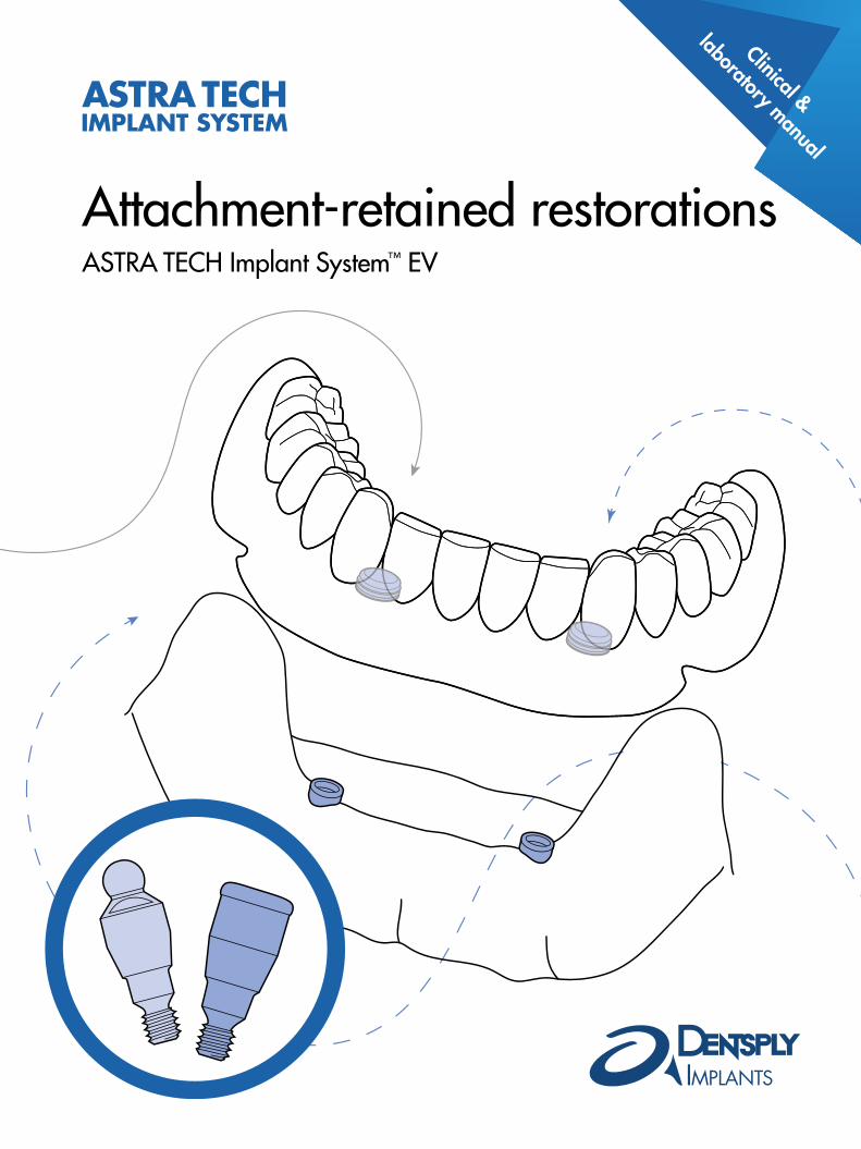
Attachment-retained restorationsASTRA TECH Implant System™ EV
Clinical &
laboratory manual
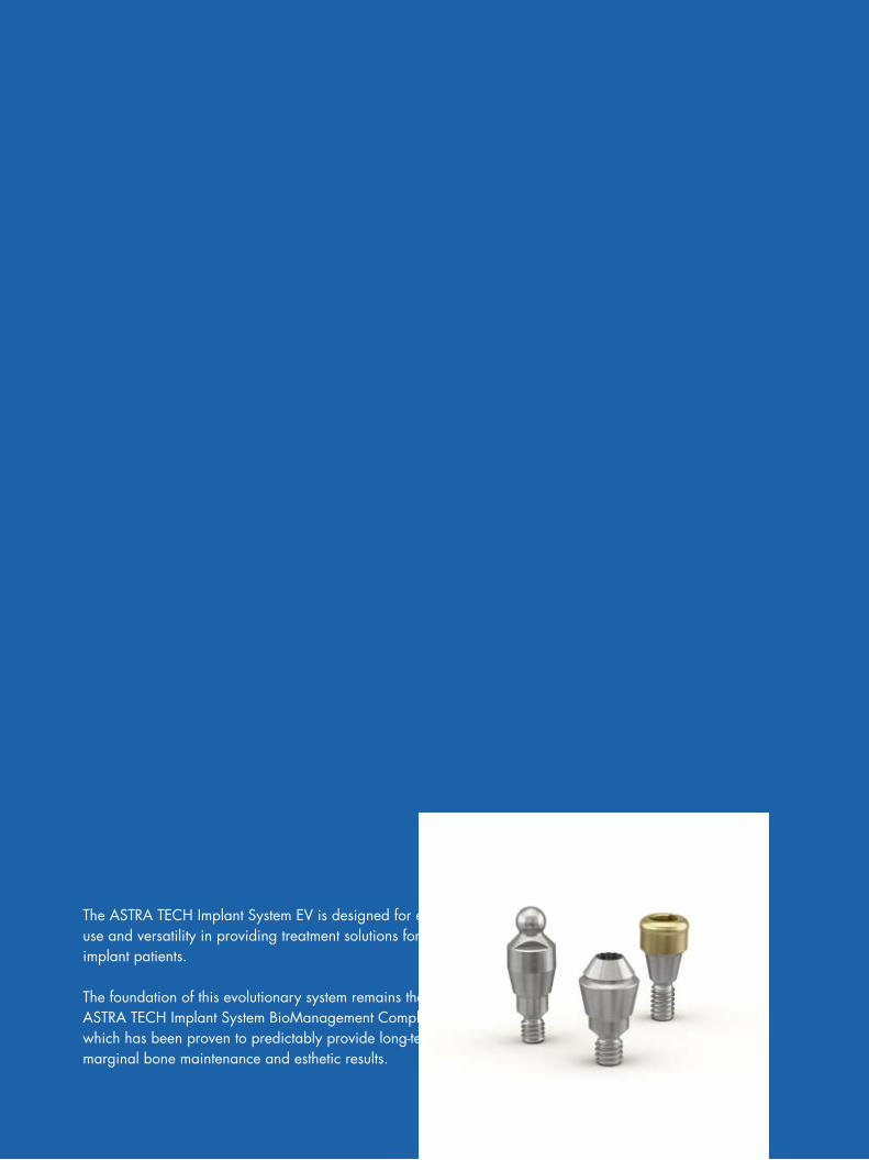
The ASTRA TECH Implant System EV is designed for ease of use and versatility in providing treatment solutions for your implant patients.
The foundation of this evolutionary system remains the unique ASTRA TECH Implant System BioManagement Complex, which has been proven to predictably provide long-term marginal bone maintenance and esthetic results.

CONTENTS
Introduction – ASTRA TECH Implant System™ EV
Restorative overview 4Abutment overview 5Implant-abutment interface connection 6Color coding 6Clinical application 7
Clinical and laboratory procedures
Complementary components 8Healing procedure – Healing Uni EV 9Final restoration – Locator™ Abutment EV 10 – Ball Abutment EV 12 – Uni Abutment EV/ATLANTIS™ ISUS 14 – Uni Abutment EV/OD Cylinder EV 16Torque Wrench EV – restorative handling 18Torque guide 20Cleaning and sterilization 21
References 23
For more information also follow the manufacturer’s instructions:
Zest Anchors– Instructions for use – LOCATOR® IMPLANT ATTACHMENT SYSTEM – LOCATOR® Implant Attachment System, Technique Manual for detailed
handling of the Locator™ Abutment
Cendres Métaux– Attachment for prosthetic dentistry for detailed handling of the Dalbo® -PLUS
Female part
This manual is designed for use by clinicians who have undergone at least basic prosthetic and in-clinic implant training. Staying current on the latest trends and treatment techniques in implant dentistry through continued education is the responsibility of the clinician.
All products may not be regulatory cleared/released/licensed in all markets. Please, contact the local DENTSPLY Implants sales office for current product assortment and availability.
To improve readability for our customers, DENTSPLY Implants does not use ® or ™ in body copy. However, DENTSPLY Implants does not waive any right to the trademark and nothing herein shall be interpreted to the contrary.
Product illustrations are not to scale.
3
Restorative overview
Restorative overview
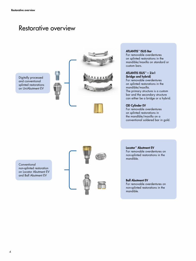
Digitally processed and conventional splinted restorations on UniAbutment EV
ATLANTIS™ ISUS BarFor removable overdentures on splinted restorations in the mandible/maxilla on standard or custom bars.
ATLANTIS ISUS™ – 2in1 (bridge and hybrid)For removable overdentures on splinted restorations in the mandible/maxilla.The primary structure is a custom bar and the secondary structure can either be a bridge or a hybrid.
OD Cylinder EVFor removable overdentures on splinted restorations in the mandible/maxilla on a conventional soldered bar in gold.
Locator™ Abutment EVFor removable overdentures on non-splinted restorations in the mandible.
Ball Abutment EVFor removable overdentures on non-splinted restorations in the mandible.
Conventional non-splinted restoration on Locator Abutment EV and Ball Abutment EV
4

Final abutments Indexing option Recommended application Features and benefits Page
Uni Abutment™ EVTitanium
Index free • Splinted restorations in the mandible/maxilla in combination with a bar
• Compatible with ATLANTIS ISUS• One prosthetic connection for all
implant interface connections
14–17
Locator™ Abutment EVTitanium
Index free • Non-splinted restorations in the mandible
• Implant interface connections (3.6–4.8 mm)
10–11
Ball Abutment EVTitanium
Index free • Non-splinted restorations in the mandible
• Implant interface connections (3.6–4.8 mm)
12–13
Abutment overview
ASTRA TECH Implant System EV includes an abutment assortment, including patient-specific abutments and a wide range of prefabricated abutments designed to satisfy all implant indications. The abutments are produced in different
materials in order to support varying loading conditions and choice of permanent restoration.Throughout this manual, symbols are used to illustrate the indexings options. Below is a comprehensive overview of the abutments and symbols.
Abutment overview
5
Introduction
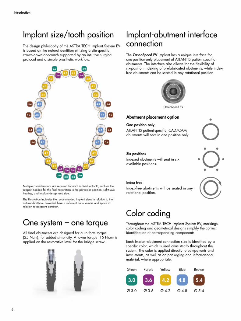
Color codingThroughout the ASTRA TECH Implant System EV, markings, color coding and geometrical designs simplify the correct identification of corresponding components.
Each implant-abutment connection size is identified by a specific color, which is used consistently throughout the system. The color is applied directly to components and instruments, as well as on packaging and informational material, where appropriate.
Ø 3.0
Green
Ø 3.6
Purple
Ø 4.2
Yellow
Ø 4.8
Blue
Ø 5.4
Brown
The design philosophy of the ASTRA TECH Implant System EV is based on the natural dentition utilizing a site-specific, crown-down approach supported by an intuitive surgical protocol and a simple prosthetic workflow.
Multiple considerations are required for each individual tooth, such as the support needed for the final restoration in the particular position, soft-tissue healing, and implant design and size.
The illustration indicates the recommended implant sizes in relation to the natural dentition, provided there is sufficient bone volume and space in relation to adjacent dentition.
Implant size/tooth position Implant-abutment interface connectionThe OsseoSpeed EV implant has a unique interface for one-position-only placement of ATLANTIS patient-specific abutments. The interface also allows for the flexibility of six-position indexing of prefabricated abutments, while index-free abutments can be seated in any rotational position.
Abutment placement option
One-position-only ATLANTIS patient-specific, CAD/CAM abutments will seat in one position only.
Six positionsIndexed abutments will seat in six available positions.
Index freeIndex-free abutments will be seated in any rotational position.
OsseoSpeed EV
One system – one torqueAll final abutments are designed for a uniform torque (25 Ncm), for added simplicity. A lower torque (15 Ncm) is applied on the restorative level for the bridge screw.
6
Introduction
The ASTRA TECH Implant System EV is designed to meet various clinical situations found in partially dentate and edentulous patients. It has been thoroughly investigated in numerous technical, experimental and prospective clinical studies, and the extensive research and documentation have yielded a simple, flexible and reliable implant system that is clinically proven to maintain marginal bone levels. A variety of prosthetic treatment options can be undertaken using implants as anchorage units.
There are several indications for overdenture treatment in connection with implant treatment. Functional, esthetic, phonetic and hygienic requirements in certain clinical situations support the use of the overdenture as a treatment option. The presence of at least one implant in each quadrant of the jaw, combined with a suitable attachment system, makes overdenture treatment a viable alternative when treating totally edentulous jaws.
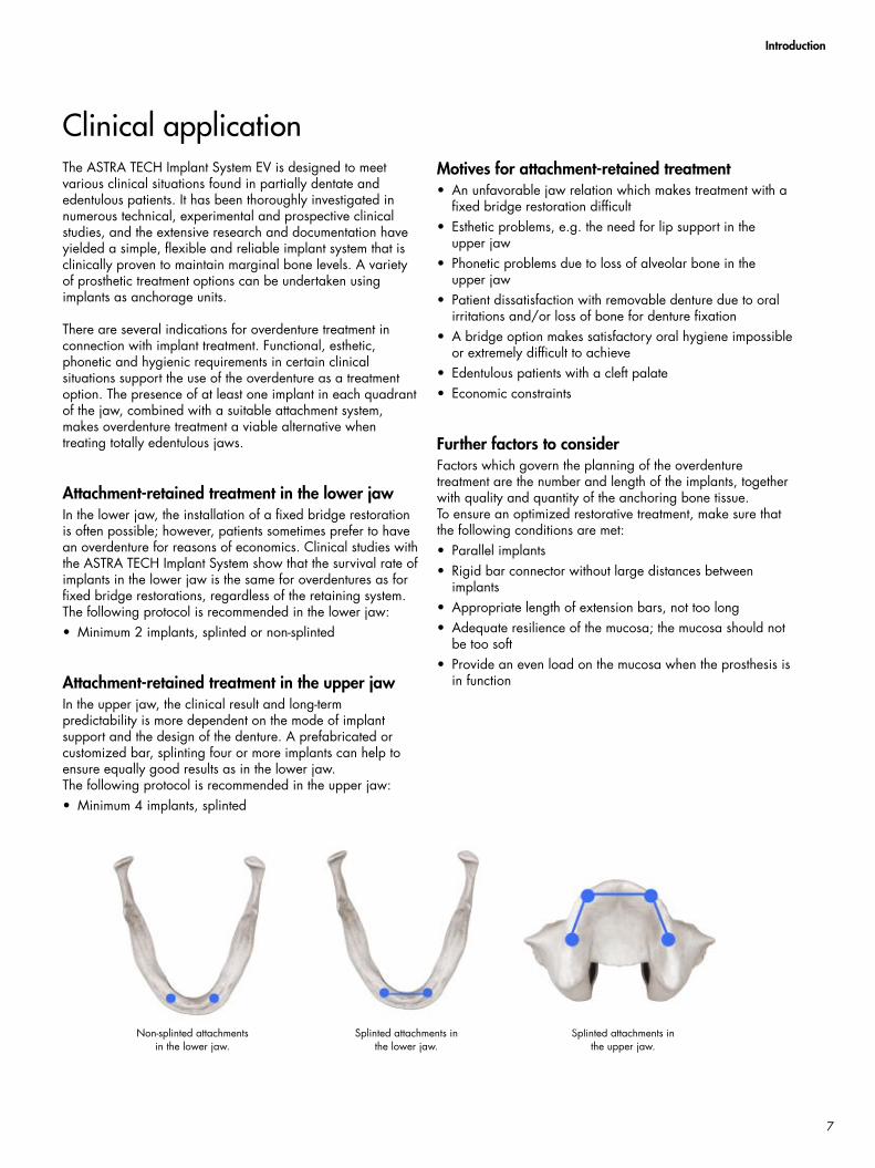
Attachment-retained treatment in the lower jaw In the lower jaw, the installation of a fixed bridge restoration is often possible; however, patients sometimes prefer to have an overdenture for reasons of economics. Clinical studies with the ASTRA TECH Implant System show that the survival rate of implants in the lower jaw is the same for overdentures as for fixed bridge restorations, regardless of the retaining system. The following protocol is recommended in the lower jaw: • Minimum 2 implants, splinted or non-splinted
Attachment-retained treatment in the upper jaw In the upper jaw, the clinical result and long-term predictability is more dependent on the mode of implant support and the design of the denture. A prefabricated or customized bar, splinting four or more implants can help to ensure equally good results as in the lower jaw. The following protocol is recommended in the upper jaw: • Minimum 4 implants, splinted
Motives for attachment-retained treatment• An unfavorable jaw relation which makes treatment with a
fixed bridge restoration difficult• Esthetic problems, e.g. the need for lip support in the
upper jaw• Phonetic problems due to loss of alveolar bone in the
upper jaw• Patient dissatisfaction with removable denture due to oral
irritations and/or loss of bone for denture fixation• A bridge option makes satisfactory oral hygiene impossible
or extremely difficult to achieve• Edentulous patients with a cleft palate• Economic constraints
Further factors to considerFactors which govern the planning of the overdenture treatment are the number and length of the implants, together with quality and quantity of the anchoring bone tissue.To ensure an optimized restorative treatment, make sure that the following conditions are met:• Parallel implants• Rigid bar connector without large distances between
implants• Appropriate length of extension bars, not too long• Adequate resilience of the mucosa; the mucosa should not
be too soft• Provide an even load on the mucosa when the prosthesis is
in function
Non-splinted attachments in the lower jaw.
Splinted attachments in the lower jaw.
Splinted attachments in the upper jaw.
Clinical application
7
Complementary components
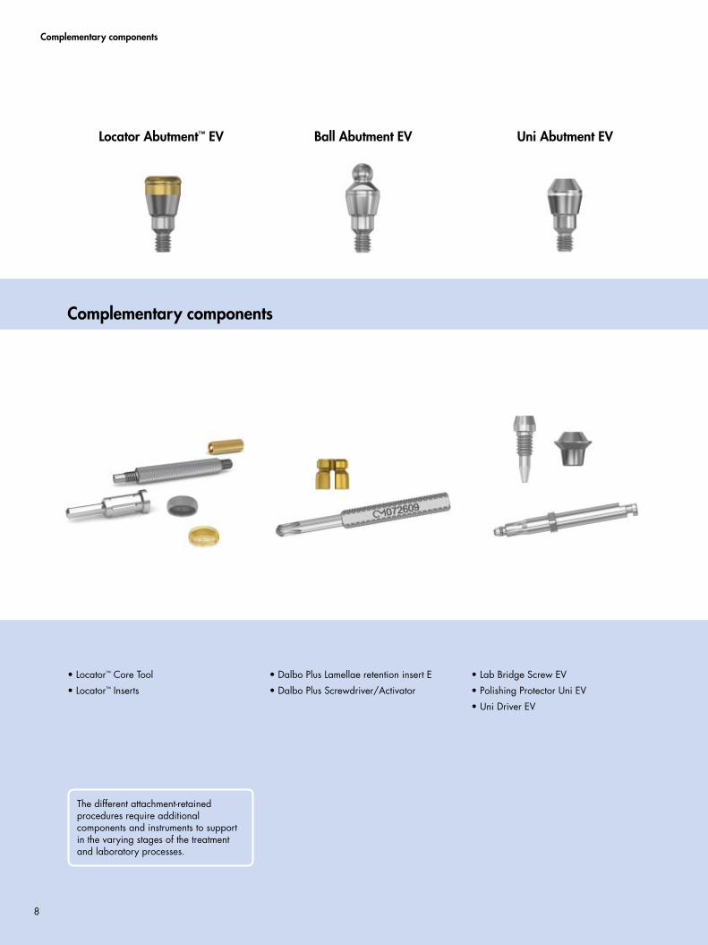
Locator Abutment™ EV Ball Abutment EV Uni Abutment EV
Complementary components
• Locator™ Core Tool
• Locator™ Inserts
• Dalbo Plus Lamellae retention insert E
• Dalbo Plus Screwdriver/Activator
• Lab Bridge Screw EV
• Polishing Protector Uni EV
• Uni Driver EV
The different attachment-retained procedures require additional components and instruments to support in the varying stages of the treatment and laboratory processes.
8
Healing procedure
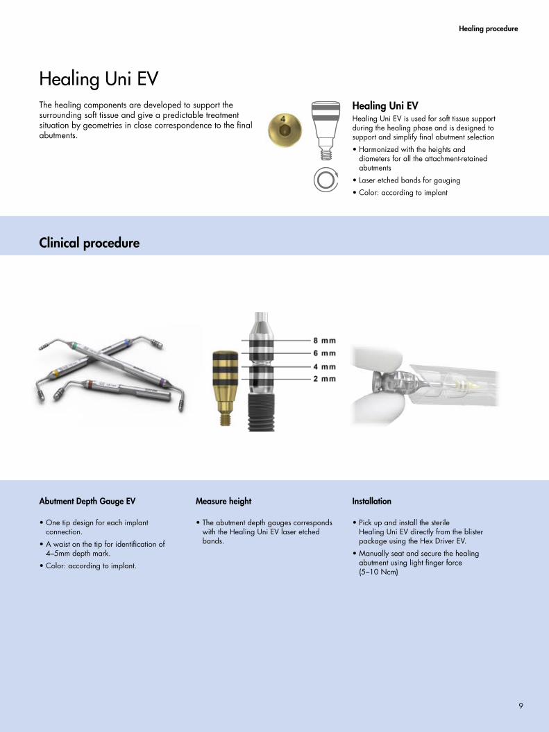
The healing components are developed to support the surrounding soft tissue and give a predictable treatment situation by geometries in close correspondence to the final abutments.
Healing Uni EVHealing Uni EV is used for soft tissue support during the healing phase and is designed to support and simplify final abutment selection
• Harmonized with the heights and diameters for all the attachment-retained abutments
• Laser etched bands for gauging
• Color: according to implant
Healing Uni EV
Clinical procedure
Installation
• Pick up and install the sterile Healing Uni EV directly from the blister package using the Hex Driver EV.
• Manually seat and secure the healing abutment using light finger force (5–10 Ncm)
Measure height
• The abutment depth gauges corresponds with the Healing Uni EV laser etched bands.
Abutment Depth Gauge EV
• One tip design for each implant connection.
• A waist on the tip for identification of 4–5mm depth mark.
• Color: according to implant.
9
Final restoration
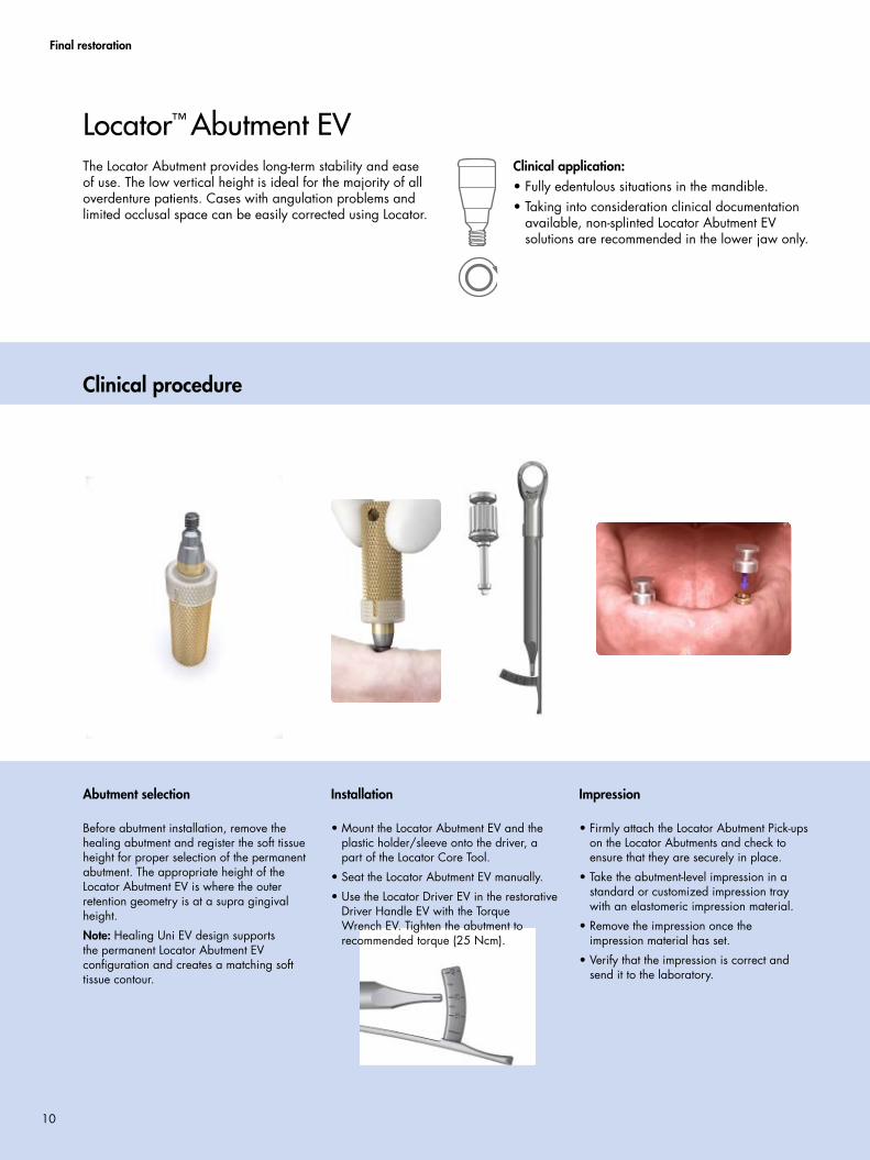
The Locator Abutment provides long-term stability and ease of use. The low vertical height is ideal for the majority of all overdenture patients. Cases with angulation problems and limited occlusal space can be easily corrected using Locator.
Clinical application:• Fully edentulous situations in the mandible.• Taking into consideration clinical documentation
available, non-splinted Locator Abutment EV solutions are recommended in the lower jaw only.
Locator™ Abutment EV
Abutment selection
Before abutment installation, remove the healing abutment and register the soft tissue height for proper selection of the permanent abutment. The appropriate height of the Locator Abutment EV is where the outer retention geometry is at a supra gingival height.
Note: Healing Uni EV design supports the permanent Locator Abutment EV configuration and creates a matching soft tissue contour.
Impression
• Firmly attach the Locator Abutment Pick-ups on the Locator Abutments and check to ensure that they are securely in place.
• Take the abutment-level impression in a standard or customized impression tray with an elastomeric impression material.
• Remove the impression once the impression material has set.
• Verify that the impression is correct and send it to the laboratory.
Clinical procedure
Installation
• Mount the Locator Abutment EV and the plastic holder/sleeve onto the driver, a part of the Locator Core Tool.
• Seat the Locator Abutment EV manually.
• Use the Locator Driver EV in the restorative Driver Handle EV with the Torque Wrench EV. Tighten the abutment to recommended torque (25 Ncm).
10
Final restoration
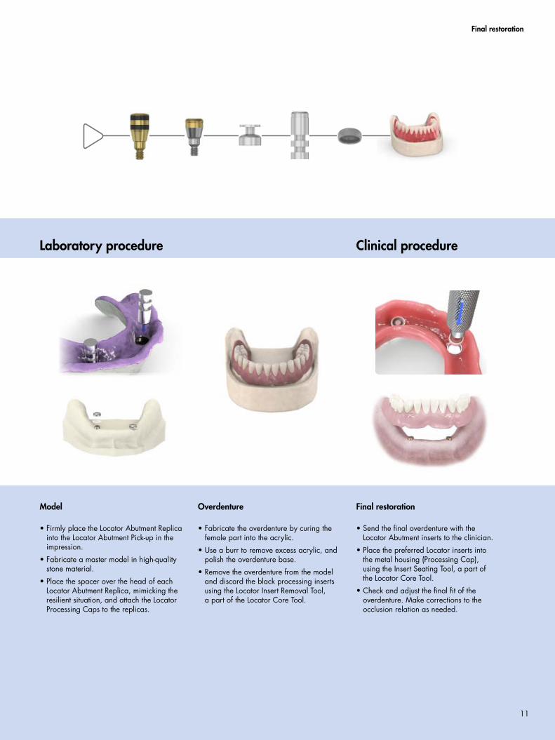
Model
• Firmly place the Locator Abutment Replica into the Locator Abutment Pick-up in the impression.
• Fabricate a master model in high-quality stone material.
• Place the spacer over the head of each Locator Abutment Replica, mimicking the resilient situation, and attach the Locator Processing Caps to the replicas.
Overdenture
• Fabricate the overdenture by curing the female part into the acrylic.
• Use a burr to remove excess acrylic, and polish the overdenture base.
• Remove the overdenture from the model and discard the black processing inserts using the Locator Insert Removal Tool, a part of the Locator Core Tool.
Final restoration
• Send the final overdenture with the Locator Abutment inserts to the clinician.
• Place the preferred Locator inserts into the metal housing (Processing Cap), using the Insert Seating Tool, a part of the Locator Core Tool.
• Check and adjust the final fit of the overdenture. Make corrections to the occlusion relation as needed.
Clinical procedure Laboratory procedure
11
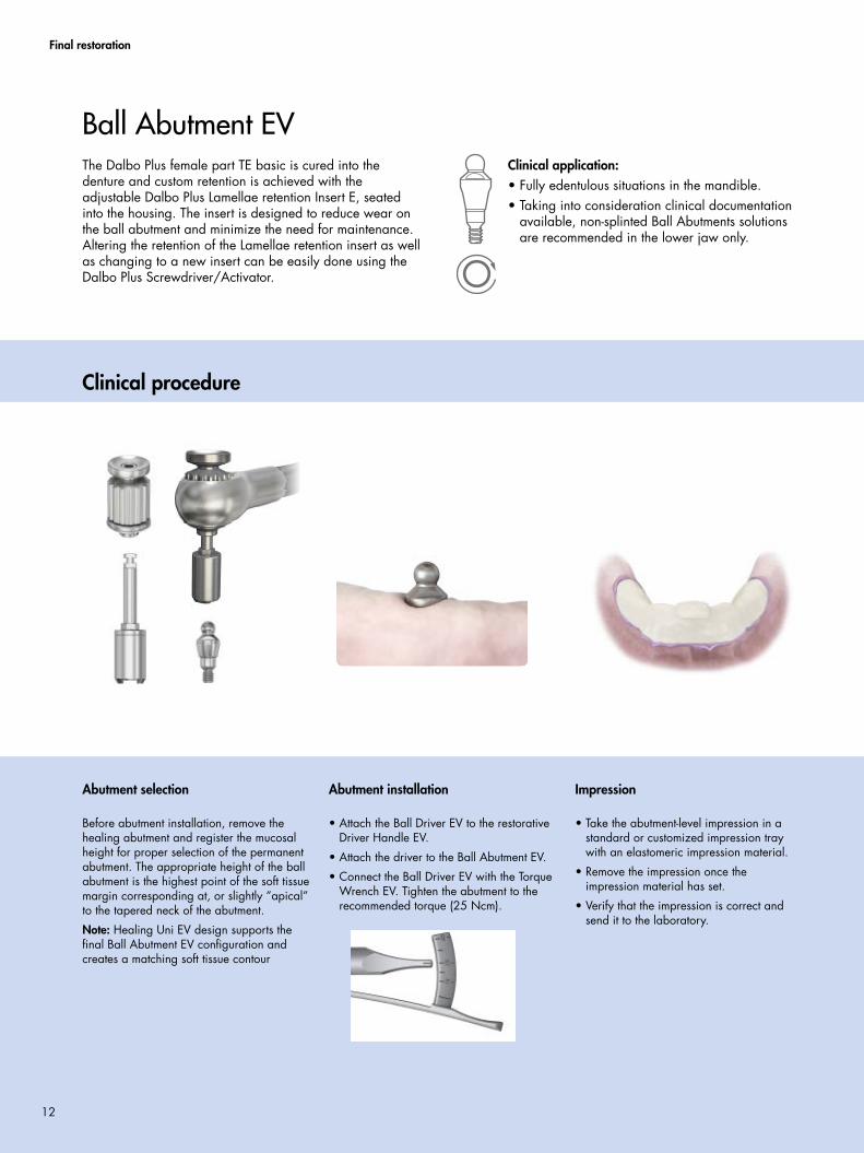
Abutment installation
• Attach the Ball Driver EV to the restorative Driver Handle EV.
• Attach the driver to the Ball Abutment EV.
• Connect the Ball Driver EV with the Torque Wrench EV. Tighten the abutment to the recommended torque (25 Ncm).
Impression
• Take the abutment-level impression in a standard or customized impression tray with an elastomeric impression material.
• Remove the impression once the impression material has set.
• Verify that the impression is correct and send it to the laboratory.
Abutment selection
Before abutment installation, remove the healing abutment and register the mucosal height for proper selection of the permanent abutment. The appropriate height of the ball abutment is the highest point of the soft tissue margin corresponding at, or slightly ”apical” to the tapered neck of the abutment.
Note: Healing Uni EV design supports the final Ball Abutment EV configuration and creates a matching soft tissue contour
Final restoration
The Dalbo Plus female part TE basic is cured into the denture and custom retention is achieved with the adjustable Dalbo Plus Lamellae retention Insert E, seated into the housing. The insert is designed to reduce wear on the ball abutment and minimize the need for maintenance. Altering the retention of the Lamellae retention insert as well as changing to a new insert can be easily done using the Dalbo Plus Screwdriver/Activator.
Clinical application:• Fully edentulous situations in the mandible.• Taking into consideration clinical documentation
available, non-splinted Ball Abutments solutions are recommended in the lower jaw only.
Ball Abutment EV
Clinical procedure
12
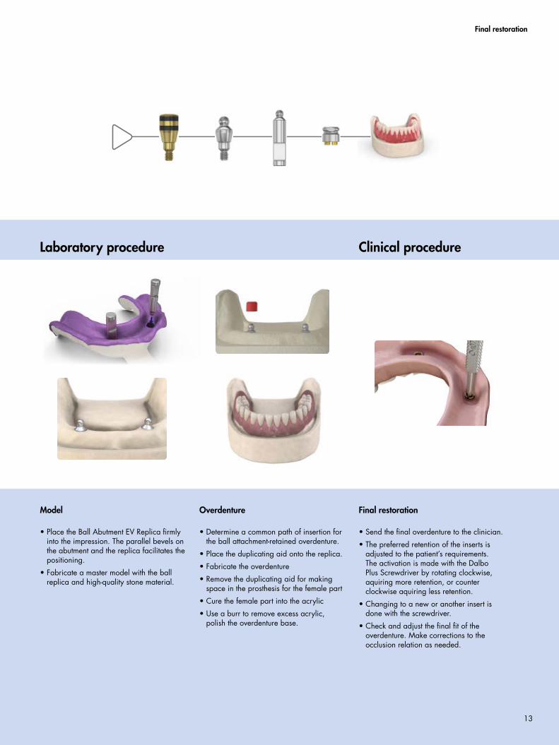
Model
• Place the Ball Abutment EV Replica firmly into the impression. The parallel bevels on the abutment and the replica facilitates the positioning.
• Fabricate a master model with the ball replica and high-quality stone material.
Final restoration
• Send the final overdenture to the clinician.
• The preferred retention of the inserts is adjusted to the patient’s requirements. The activation is made with the Dalbo Plus Screwdriver by rotating clockwise, aquiring more retention, or counter clockwise aquiring less retention.
• Changing to a new or another insert is done with the screwdriver.
• Check and adjust the final fit of the overdenture. Make corrections to the occlusion relation as needed.
Overdenture
• Determine a common path of insertion for the ball attachment-retained overdenture.
• Place the duplicating aid onto the replica.
• Fabricate the overdenture
• Remove the duplicating aid for making space in the prosthesis for the female part
• Cure the female part into the acrylic
• Use a burr to remove excess acrylic, polish the overdenture base.
Final restoration
Clinical procedureLaboratory procedure
13
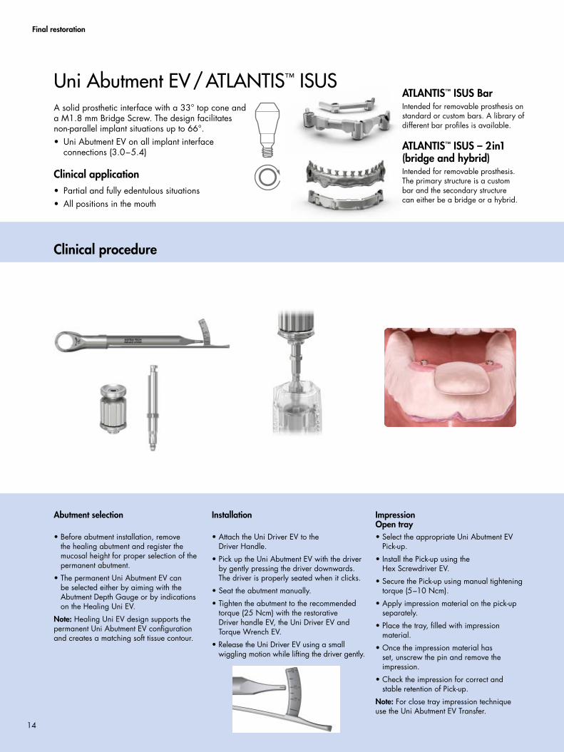
Installation
• Attach the Uni Driver EV to the Driver Handle.
• Pick up the Uni Abutment EV with the driver by gently pressing the driver downwards. The driver is properly seated when it clicks.
• Seat the abutment manually.
• Tighten the abutment to the recommended torque (25 Ncm) with the restorative Driver handle EV, the Uni Driver EV and Torque Wrench EV.
• Release the Uni Driver EV using a small wiggling motion while lifting the driver gently.
Impression Open tray• Select the appropriate Uni Abutment EV
Pick-up.
• Install the Pick-up using the Hex Screwdriver EV.
• Secure the Pick-up using manual tightening torque (5–10 Ncm).
• Apply impression material on the pick-up separately.
• Place the tray, filled with impression material.
• Once the impression material has set, unscrew the pin and remove the impression.
• Check the impression for correct and stable retention of Pick-up.
Note: For close tray impression technique use the Uni Abutment EV Transfer.
Abutment selection
• Before abutment installation, remove the healing abutment and register the mucosal height for proper selection of the permanent abutment.
• The permanent Uni Abutment EV can be selected either by aiming with the Abutment Depth Gauge or by indications on the Healing Uni EV.
Note: Healing Uni EV design supports the permanent Uni Abutment EV configuration and creates a matching soft tissue contour.
Clinical procedure
Uni Abutment EV/ATLANTIS™ ISUS
Final restoration
A solid prosthetic interface with a 33° top cone and a M1.8 mm Bridge Screw. The design facilitates non-parallel implant situations up to 66°.• Uni Abutment EV on all implant interface
connections (3.0–5.4)
Clinical application• Partial and fully edentulous situations• All positions in the mouth
ATLANTIS™ ISUS BarIntended for removable prosthesis on standard or custom bars. A library of different bar profiles is available.
ATLANTIS™ ISUS – 2in1 (bridge and hybrid)Intended for removable prosthesis. The primary structure is a custom bar and the secondary structure can either be a bridge or a hybrid.
14
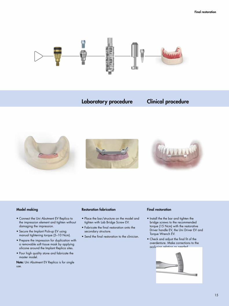
Restoration fabrication
• Place the bar/structure on the model and tighten with Lab Bridge Screw EV.
• Fabricate the final restoration onto the secondary structure.
• Send the final restoration to the clinician.
Model making
• Connect the Uni Abutment EV Replica to the impression element and tighten without damaging the impression.
• Secure the Implant Pick-up EV using manual tightening torque (5–10 Ncm).
• Prepare the impression for duplication with a removable soft tissue mask by applying silicone around the Implant Replica sites.
• Pour high quality stone and fabricate the master model.
Note: Uni Abutment EV Replica is for single use.
Final restoration
• Install the the bar and tighten the bridge screws to the recommended torque (15 Ncm) with the restorative Driver handle EV, the Uni Driver EV and Torque Wrench EV.
• Check and adjust the final fit of the overdenture. Make corrections to the occlusion relation as needed.
Laboratory procedure Clinical procedure
Final restoration
15
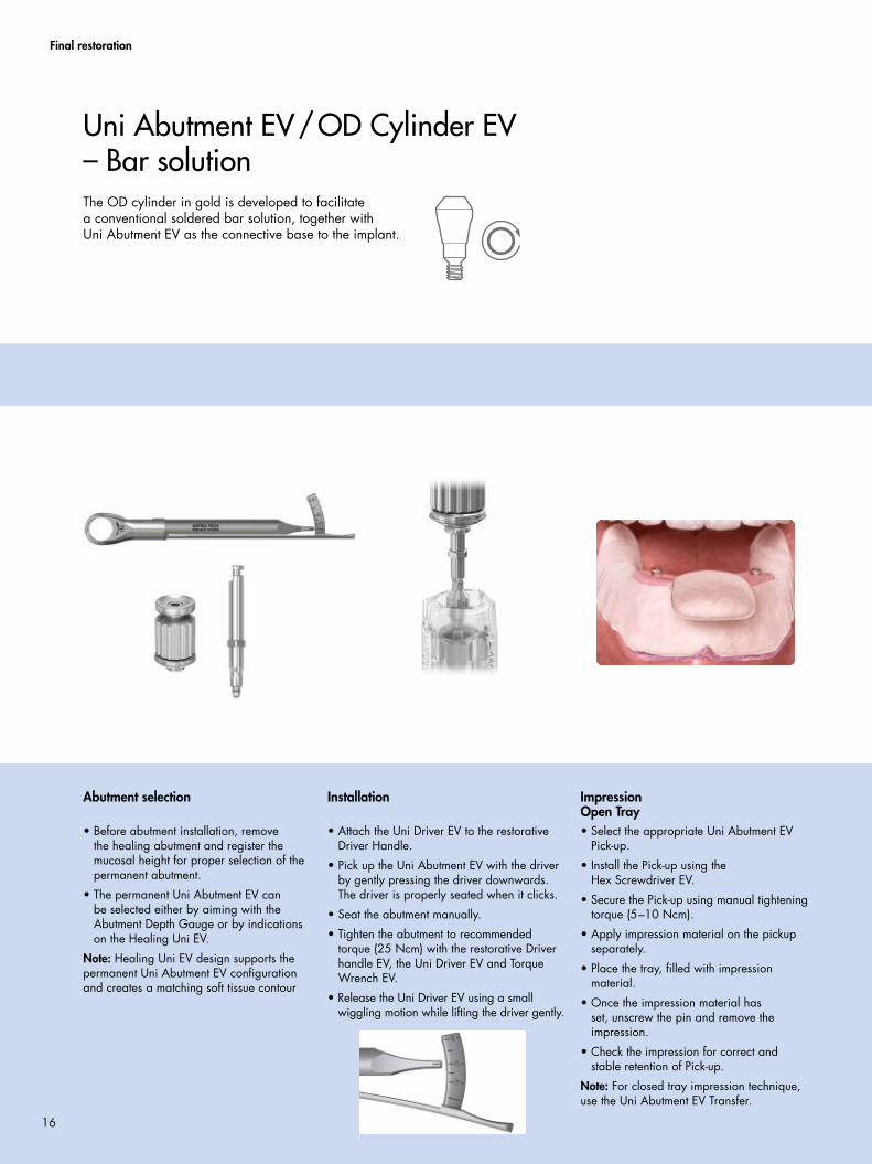
Impression Open Tray• Select the appropriate Uni Abutment EV
Pick-up.
• Install the Pick-up using the Hex Screwdriver EV.
• Secure the Pick-up using manual tightening torque (5–10 Ncm).
• Apply impression material on the pickup separately.
• Place the tray, filled with impression material.
• Once the impression material has set, unscrew the pin and remove the impression.
• Check the impression for correct and stable retention of Pick-up.
Note: For closed tray impression technique, use the Uni Abutment EV Transfer.
The OD cylinder in gold is developed to facilitate a conventional soldered bar solution, together with Uni Abutment EV as the connective base to the implant.
Uni Abutment EV/OD Cylinder EV – Bar solution
Final restoration
Installation
• Attach the Uni Driver EV to the restorative Driver Handle.
• Pick up the Uni Abutment EV with the driver by gently pressing the driver downwards. The driver is properly seated when it clicks.
• Seat the abutment manually.
• Tighten the abutment to recommended torque (25 Ncm) with the restorative Driver handle EV, the Uni Driver EV and Torque Wrench EV.
• Release the Uni Driver EV using a small wiggling motion while lifting the driver gently.
Abutment selection
• Before abutment installation, remove the healing abutment and register the mucosal height for proper selection of the permanent abutment.
• The permanent Uni Abutment EV can be selected either by aiming with the Abutment Depth Gauge or by indications on the Healing Uni EV.
Note: Healing Uni EV design supports the permanent Uni Abutment EV configuration and creates a matching soft tissue contour
16
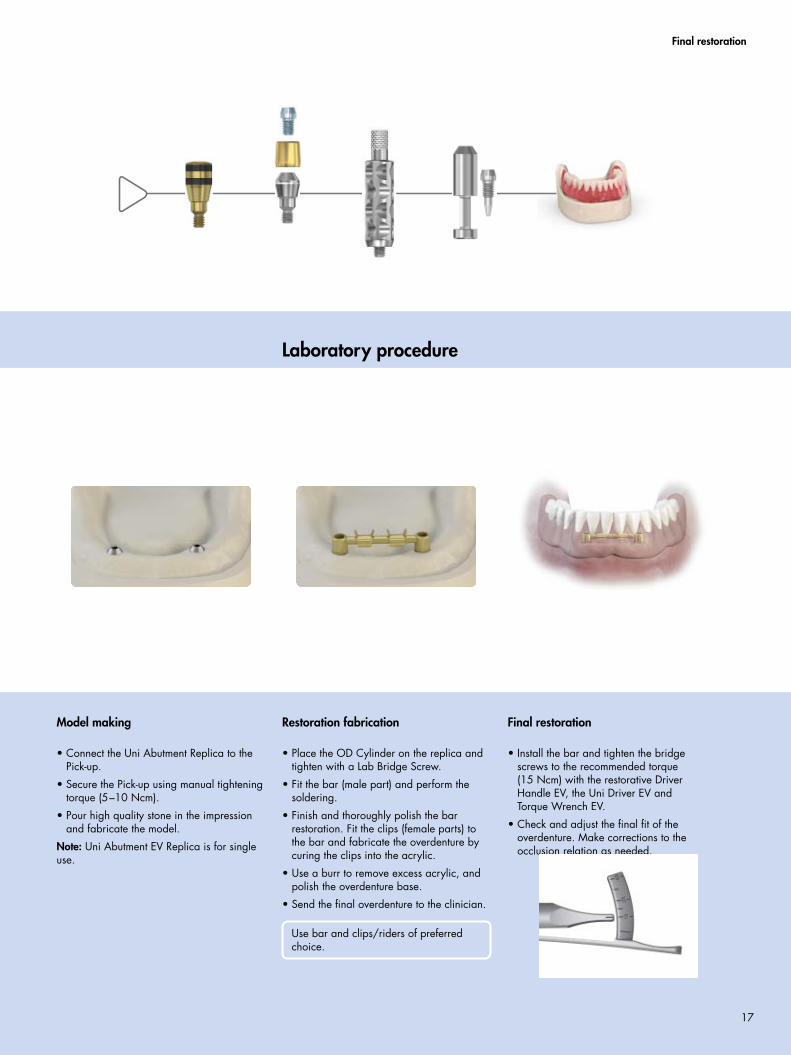
Laboratory procedure
Final restoration
Restoration fabrication
• Place the OD Cylinder on the replica and tighten with a Lab Bridge Screw.
• Fit the bar (male part) and perform the soldering.
• Finish and thoroughly polish the bar restoration. Fit the clips (female parts) to the bar and fabricate the overdenture by curing the clips into the acrylic.
• Use a burr to remove excess acrylic, and polish the overdenture base.
• Send the final overdenture to the clinician.
Use bar and clips/riders of preferred choice.
Model making
• Connect the Uni Abutment Replica to the Pick-up.
• Secure the Pick-up using manual tightening torque (5–10 Ncm).
• Pour high quality stone in the impression and fabricate the model.
Note: Uni Abutment EV Replica is for single use.
Final restoration
• Install the bar and tighten the bridge screws to the recommended torque (15 Ncm) with the restorative Driver Handle EV, the Uni Driver EV and Torque Wrench EV.
• Check and adjust the final fit of the overdenture. Make corrections to the occlusion relation as needed.
17
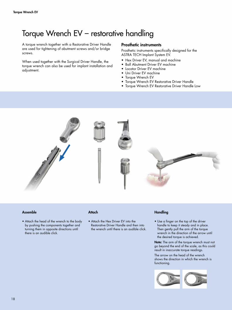
Torque Wrench EV
A torque wrench together with a Restorative Driver Handle are used for tightening of abutment screws and/or bridge screws.
When used together with the Surgical Driver Handle, the torque wrench can also be used for implant installation and adjustment.
Torque Wrench EV – restorative handlingProsthetic instrumentsProsthetic instruments specifically designed for the ASTRA TECH Implant System EV.• Hex Driver EV, manual and machine• Ball Abutment Driver EV machine• Locator Driver EV machine• Uni Driver EV machine• Torque Wrench EV• Torque Wrench EV Restorative Driver Handle• Torque Wrench EV Restorative Driver Handle Low
Handling
• Use a finger on the top of the driver handle to keep it steady and in place. Then gently pull the arm of the torque wrench in the direction of the arrow until the desired torque is achieved.
Note: The arm of the torque wrench must not go beyond the end of the scale, as this could result in inaccurate torque readings.
The arrow on the head of the wrench shows the direction in which the wrench is functioning.
Attach
• Attach the Hex Driver EV into the Restorative Driver Handle and then into the wrench until there is an audible click.
Assemble
• Attach the head of the wrench to the body by pushing the components together and turning them in opposite directions until there is an audible click.
18
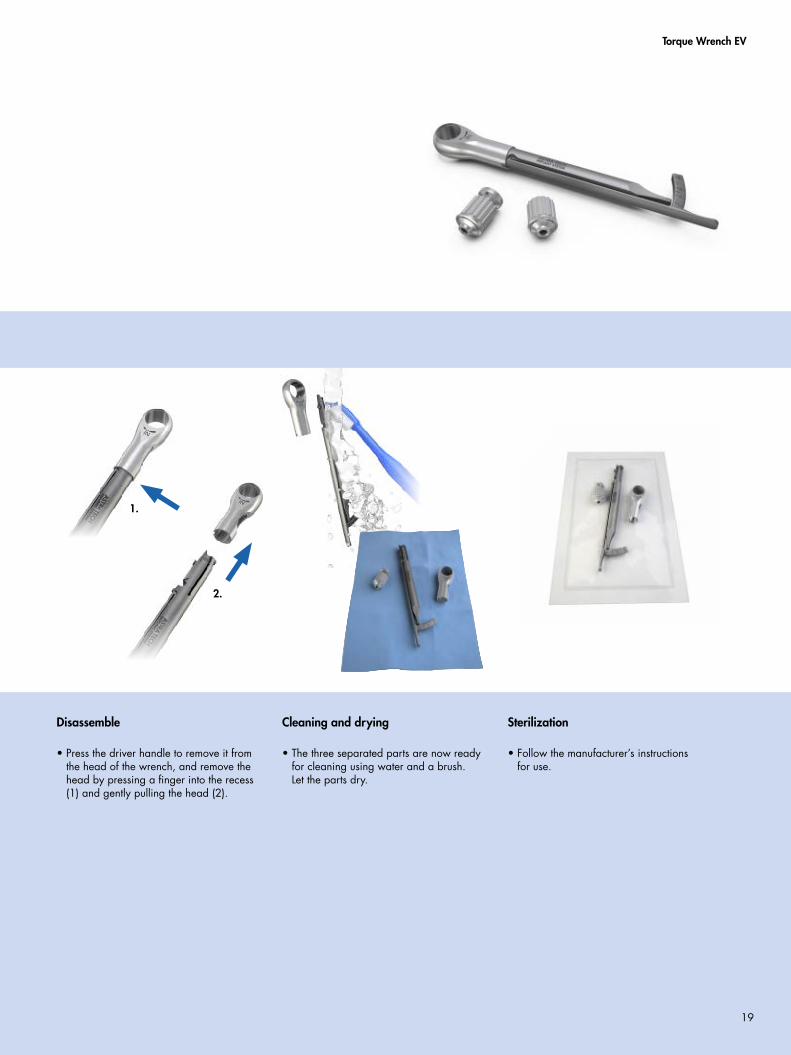
Torque Wrench EV
Sterilization
• Follow the manufacturer’s instructions for use.
Cleaning and drying
• The three separated parts are now ready for cleaning using water and a brush. Let the parts dry.
Disassemble
• Press the driver handle to remove it from the head of the wrench, and remove the head by pressing a finger into the recess (1) and gently pulling the head (2).
1.
2.
19
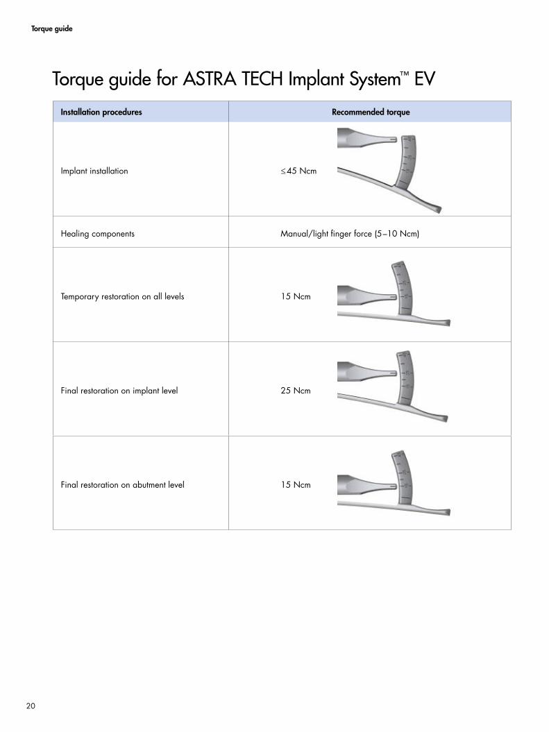
Torque guide
Installation procedures Recommended torque
Implant installation ≤45 Ncm
Healing components Manual/light finger force (5–10 Ncm)
Temporary restoration on all levels 15 Ncm
Final restoration on implant level 25 Ncm
Final restoration on abutment level 15 Ncm
Torque guide for ASTRA TECH Implant System™ EV
20
Cleaning and sterilization
All drills, except the single use Precision Drill EV, can be used approximately ten times. If drills are not reused, dispose them in a sharps container immediately after the implant procedure is completed.
Note: Single use products should not be reused.
Remove residual tissue or bone debris by immersing the used products in lukewarm water (<40°C/104°F). Do not use fixation agents or hot water as this could influence subsequent cleaning results. Products should be kept in a wet environment until the next step is initiated. For Direct Driver EV Ø 3.3, Ø 4 and Ball Abutment Driver EV storage in a wet environment is mandatory.
If cleaning is delayed more than 120 minutes, place the devices in a bath of a cleaning and disinfection solution to avoid drying of soil and/or debris, blood and other contaminations.
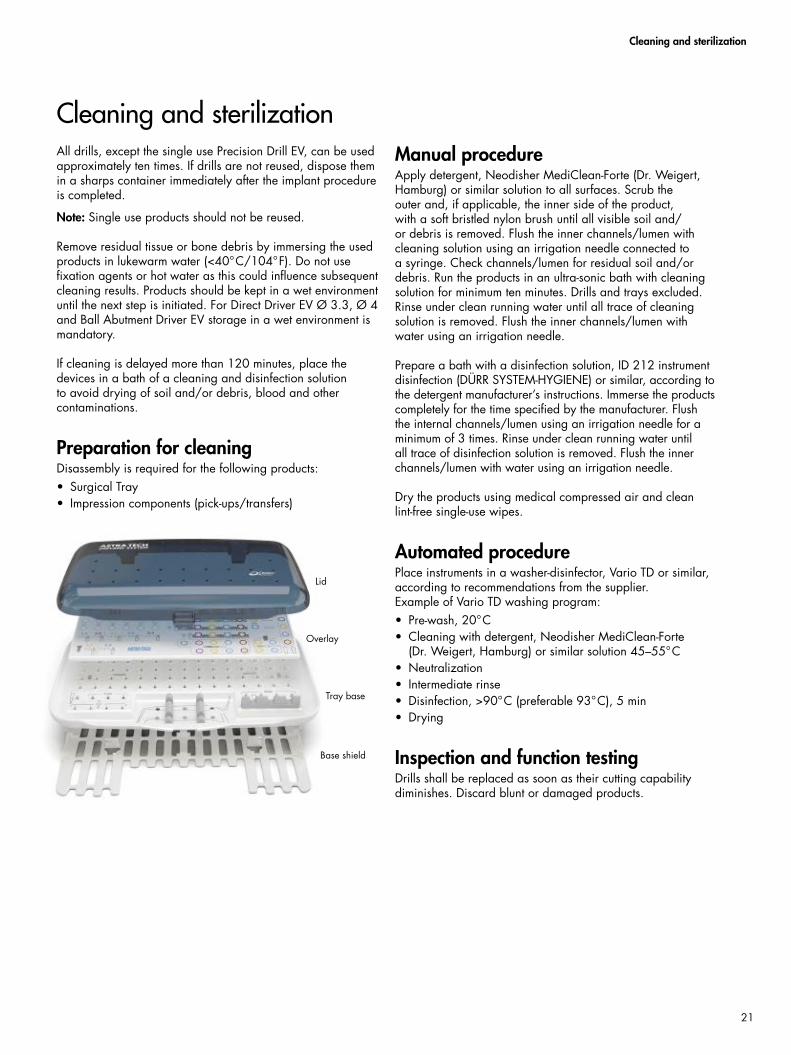
Preparation for cleaningDisassembly is required for the following products:• Surgical Tray• Impression components (pick-ups/transfers)
Manual procedureApply detergent, Neodisher MediClean-Forte (Dr. Weigert, Hamburg) or similar solution to all surfaces. Scrub the outer and, if applicable, the inner side of the product, with a soft bristled nylon brush until all visible soil and/or debris is removed. Flush the inner channels/lumen with cleaning solution using an irrigation needle connected to a syringe. Check channels/lumen for residual soil and/or debris. Run the products in an ultra-sonic bath with cleaning solution for minimum ten minutes. Drills and trays excluded. Rinse under clean running water until all trace of cleaning solution is removed. Flush the inner channels/lumen with water using an irrigation needle.
Prepare a bath with a disinfection solution, ID 212 instrument disinfection (DÜRR SYSTEM-HYGIENE) or similar, according to the detergent manufacturer’s instructions. Immerse the products completely for the time specified by the manufacturer. Flush the internal channels/lumen using an irrigation needle for a minimum of 3 times. Rinse under clean running water until all trace of disinfection solution is removed. Flush the inner channels/lumen with water using an irrigation needle.
Dry the products using medical compressed air and clean lint-free single-use wipes.
Automated procedurePlace instruments in a washer-disinfector, Vario TD or similar, according to recommendations from the supplier.Example of Vario TD washing program:• Pre-wash, 20°C• Cleaning with detergent, Neodisher MediClean-Forte
(Dr. Weigert, Hamburg) or similar solution 45–55°C• Neutralization• Intermediate rinse• Disinfection, >90°C (preferable 93°C), 5 min• Drying
Inspection and function testingDrills shall be replaced as soon as their cutting capability diminishes. Discard blunt or damaged products.
Cleaning and sterilization
Lid
Overlay
Base shield
Tray base
21
Cleaning and sterilization
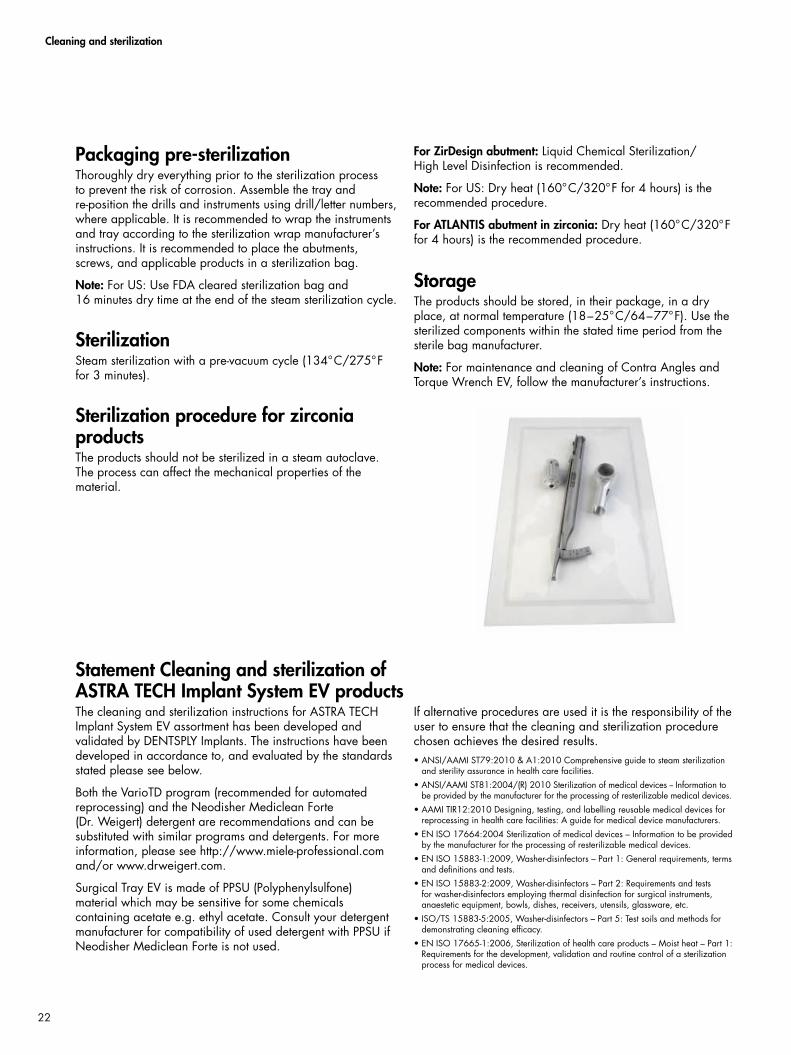
Packaging pre-sterilizationThoroughly dry everything prior to the sterilization process to prevent the risk of corrosion. Assemble the tray and re-position the drills and instruments using drill/letter numbers, where applicable. It is recommended to wrap the instruments and tray according to the sterilization wrap manufacturer’s instructions. It is recommended to place the abutments, screws, and applicable products in a sterilization bag.
Note: For US: Use FDA cleared sterilization bag and 16 minutes dry time at the end of the steam sterilization cycle.
SterilizationSteam sterilization with a pre-vacuum cycle (134°C/275°F for 3 minutes).
Sterilization procedure for zirconia productsThe products should not be sterilized in a steam autoclave. The process can affect the mechanical properties of the material.
For ZirDesign abutment: Liquid Chemical Sterilization/High Level Disinfection is recommended.
Note: For US: Dry heat (160°C/320°F for 4 hours) is the recommended procedure.
For ATLANTIS abutment in zirconia: Dry heat (160°C/320°F for 4 hours) is the recommended procedure.
StorageThe products should be stored, in their package, in a dry place, at normal temperature (18–25°C/64–77°F). Use the sterilized components within the stated time period from the sterile bag manufacturer.
Note: For maintenance and cleaning of Contra Angles and Torque Wrench EV, follow the manufacturer’s instructions.
Statement Cleaning and sterilization of ASTRA TECH Implant System EV productsThe cleaning and sterilization instructions for ASTRA TECH Implant System EV assortment has been developed and validated by DENTSPLY Implants. The instructions have been developed in accordance to, and evaluated by the standards stated please see below.
Both the VarioTD program (recommended for automated reprocessing) and the Neodisher Mediclean Forte (Dr. Weigert) detergent are recommendations and can be substituted with similar programs and detergents. For more information, please see http://www.miele-professional.com and/or www.drweigert.com.
Surgical Tray EV is made of PPSU (Polyphenylsulfone) material which may be sensitive for some chemicals containing acetate e.g. ethyl acetate. Consult your detergent manufacturer for compatibility of used detergent with PPSU if Neodisher Mediclean Forte is not used.
If alternative procedures are used it is the responsibility of the user to ensure that the cleaning and sterilization procedure chosen achieves the desired results.• ANSI/AAMI ST79:2010 & A1:2010 Comprehensive guide to steam sterilization
and sterility assurance in health care facilities.• ANSI/AAMI ST81:2004/(R) 2010 Sterilization of medical devices -- Information to
be provided by the manufacturer for the processing of resterilizable medical devices.• AAMI TIR12:2010 Designing, testing, and labelling reusable medical devices for
reprocessing in health care facilities: A guide for medical device manufacturers.• EN ISO 17664:2004 Sterilization of medical devices – Information to be provided
by the manufacturer for the processing of resterilizable medical devices.• EN ISO 15883-1:2009, Washer-disinfectors – Part 1: General requirements, terms
and definitions and tests. • EN ISO 15883-2:2009, Washer-disinfectors – Part 2: Requirements and tests
for washer-disinfectors employing thermal disinfection for surgical instruments, anaestetic equipment, bowls, dishes, receivers, utensils, glassware, etc.
• ISO/TS 15883-5:2005, Washer-disinfectors – Part 5: Test soils and methods for demonstrating cleaning efficacy.
• EN ISO 17665-1:2006, Sterilization of health care products – Moist heat – Part 1: Requirements for the development, validation and routine control of a sterilization process for medical devices.
22
References
Key references* supporting attachment-retained restorations with ASTRA TECH Implant System™
*For the complete reference list, see www.dentsplyimplants.com
23
Non-splinted restorationsCooper LF, Moriarty JD, Guckes AD, et al. Five-year prospective evaluation of mandibular overdentures retained by two microthreaded, TiOblast nonsplinted implants and retentive ball anchors. Int J Oral Maxi llofac Implants 2008;23(4):696-704.
De Bruyn H, Besseler J, Raes F, Vaneker M. Clinical outcome of overdenture treatment on two nonsubmerged and nonsplinted Astra Tech Microthread implants. Clin Impl Dent Rel Res 2009;11(2):81-9.
Geckili O, Bilhan H, Bilgin T. Impact of mandibular two-implant retained overdentures on life quality in a group of elderly Turkish edentulous patients. Arch Gerontol Geriatr 2011;53(2):233-6.
Geckili O, Bilhan H, Mumcu E, Bilgin T. Three-year radiologic follow-up of marginal bone loss around titanium dioxidegrit-blasted dental implants with and without fluoride treatment. Int J Oral Maxi llofac Implants 2011;26(2):319-24.
Splinted restorationsGulje F, Raghoebar GM, Ter Meulen JW, Vissink A, Meijer HJ. Mandibular overdentures supported by 6-mm dental implants: A 1-year prospective cohort study. Clin Impl Dent Rel Res 2011;14(Supplement 1):e59-e66.
Slot W, Raghoebar GM, Vissink A, Meijer HJ. Maxillary overdentures supported by four or six implants in the anterior region; 1-year results from a randomized controlled trial. J Clin Periodontol 2013;40(3):303-10.
Slot W, Raghoebar GM, Vissink A, Meijer HJ. Maxillary overdentures supported by anteriorly or posteriorly placed implants opposed by a natural dentition in the mandible: A 1-year prospective case series study. Clin Implant Dent Relat Res 2012;E-pub May 15, doi:10.1111/j.1708-8208.2012.00459.x.
Vroom MG, Sipos P, de Lange GL, et al. Effect of surface topography of screw-shaped titanium implants in humans on clinical and radiographic parameters: a 12-year prospective study. Clin Oral Implants Res 2009;20(11):1231-39.
Combination of attachment systemsBilhan H, Geckili O, Sulun T, Bilgin T. A quality-of-life comparison between self-aligning and ball attachment systems for two-implant-retained mandibular overdentures. J Oral Implantol 2010;37(sp1):167-73.
Geckili O, Bilhan H, Mumcu E. Clinical and radiographic evaluation of three-implant-retained mandibular overdentures: a 3-year retrospective study. Quintessence Int 2011;42(9):721-8.
Gotfredsen K, Holm B. Implant-supported mandibular overdentures retained with ball or bar attachments: a randomized prospective 5-year study. Int J Prosthodont 2000;13(2):125-30. ID No. 75355
Mumcu E, Bilhan H, Geckili O. The effect of attachment type and implant number on satisfaction and quality of life of mandibular implant-retained overdenture wearers. Gerodontology 2012;29(2):e618-23.
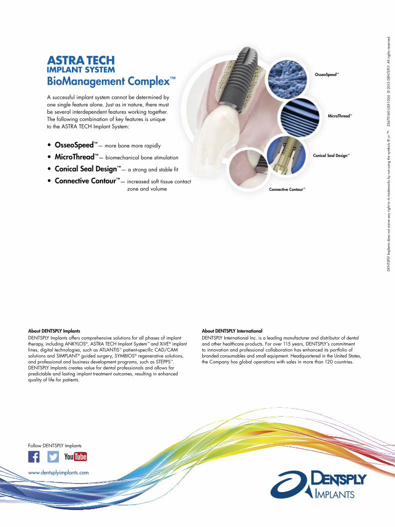
A successful implant system cannot be determined by one single feature alone. Just as in nature, there must be several interdependent features working together. The following combination of key features is unique to the ASTRA TECH Implant System:
• OsseoSpeed™— more bone more rapidly
• MicroThread™— biomechanical bone stimulation
• Conical Seal Design™— a strong and stable fit
• Connective Contour™— increased soft tissue contact zone and volume
OsseoSpeed™
MicroThread™
Conical Seal Design™
Connective Contour™
BioManagement Complex™
www.dentsplyimplants.com
About DENTSPLY ImplantsDENTSPLY Implants offers comprehensive solutions for all phases of implant therapy, including ANKYLOS®, ASTRA TECH Implant System™ and XiVE® implant lines, digital technologies, such as ATLANTIS™ patient-specific CAD/CAM solutions and SIMPLANT® guided surgery, SYMBIOS® regenerative solutions, and professional and business development programs, such as STEPPS™. DENTSPLY Implants creates value for dental professionals and allows for predictable and lasting implant treatment outcomes, resulting in enhanced quality of life for patients.
About DENTSPLY InternationalDENTSPLY International Inc. is a leading manufacturer and distributor of dental and other healthcare products. For over 115 years, DENTSPLY’s commitment to innovation and professional collaboration has enhanced its portfolio of branded consumables and small equipment. Headquartered in the United States, the Company has global operations with sales in more than 120 countries.
DEN
TSPL
Y Im
plan
ts d
oes
not w
aive
any
rig
ht to
its
trade
mar
ks b
y no
t usi
ng th
e sy
mbo
ls ®
or ™
. 32
6701
60-U
SX-1
504
© 2
015
DEN
TSPL
Y. A
ll rig
hts
rese
rved
Follow DENTSPLY Implants