ATTACHMENT F-5 O’HARE MODERNIZATION EIS RAILROAD NOISE … · O’HARE MODERNIZATION EIS RAILROAD...
21
Chicago O’Hare International Airport Final EIS Appendix F F-485 July 2005 ATTACHMENT F-5 O’HARE MODERNIZATION EIS RAILROAD NOISE AND VIBRATION TECHNICAL REPORT (10/2004)
Transcript of ATTACHMENT F-5 O’HARE MODERNIZATION EIS RAILROAD NOISE … · O’HARE MODERNIZATION EIS RAILROAD...
Chicago O’Hare International Airport Final EIS
Appendix F F-485 July 2005
ATTACHMENT F-5
O’HARE MODERNIZATION EIS RAILROAD NOISE AND VIBRATION TECHNICAL
REPORT (10/2004)

This page was intentionally left blank.
O’Hare Modernization EIS Railroad Noise and Vibration Technical Report October 2004 Jacobs Civil Inc. Mark F. Wegener, P.E.
Page 1
Table of Contents Overview............................................................................................................................. 2 Noise and Vibration Screening Procedures ........................................................................ 2 Inventory of Noise –Sensitive Sites.................................................................................... 3
Table 1 – Receivers and Receiver Clusters..................................................................... 3 Figure 1 – Proposed Plan ................................................................................................ 4 Figure 2 – Noise-Sensitive Areas and Receiver Locations............................................. 5
Estimates of Existing Noise Conditions ............................................................................. 6 Table 2 – Existing Noise Level Estimates ...................................................................... 6
Predictions of Project Noise................................................................................................ 7 Figure 3 – Project Noise as a Function of Distance from Rail Centerline...................... 8 Table 3 – Project Noise Levels ....................................................................................... 8
Noise Impact Criteria .......................................................................................................... 9 Noise Impact Assessment ................................................................................................... 9
Table 4 – Project Noise Impacts ..................................................................................... 9 Noise Mitigation ............................................................................................................... 10 Construction Noise Impacts.............................................................................................. 11 Conclusions....................................................................................................................... 11 References......................................................................................................................... 12 Appendix – FTA Manual Tables and Figures................................................................. A-1
Table 5-1 ..................................................................................................................... A-1 Figure 5-2.................................................................................................................... A-1 Table 5-2 ..................................................................................................................... A-2 Table 5-7 ..................................................................................................................... A-3 Figure 3-1.................................................................................................................... A-4 Table 3-1 ..................................................................................................................... A-5 Table 12-1 ................................................................................................................... A-6
Page 2
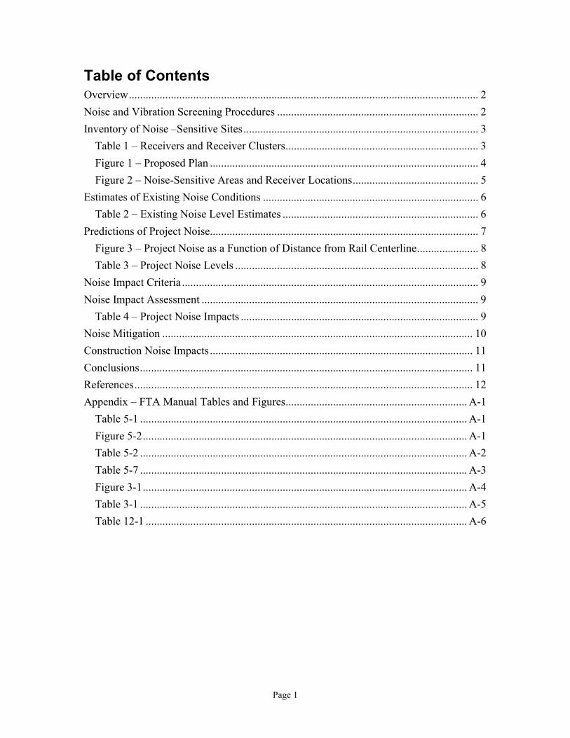
Overview Alternative C includes construction of new facilities that require the relocation of the Union Pacific Railroad (UPRR) tracks in the southwest corner of the airport property. The new facilities in the Build Alternative as proposed by the City of Chicago include runways 10L-28R, 10C-28C, and 10R-28L, a number of air carrier cargo and maintenance buildings, and the terminal on the west airfield that could affect the railroad tracks. The existing UPRR tracks are two parallel tracks that enter the proposed airport property from the south near the intersections of existing Irving Park Road and Taft Road. They curve to the west and exit the proposed airport property near the intersection of York Road and Thorndale Avenue, after which they continue north parallel to York Road. The relocated UPRR tracks would be further south and west of the existing tracks, so that they generally run parallel to and adjacent to the proposed Irving Park Road and York Road. A plan of the existing and relocated UPRR tracks is shown in Figure 1. The land that is between the existing and relocated UPRR tracks would be acquired by the airport so that all of the land north east of the relocated UPRR tracks would be airport property. The land south and west of the relocated tracks is currently and would continue to be used for rail yard, commercial, industrial, and residential purposes. This report presents an analysis of the effect of railroad noise on the lands surrounding the relocated tracks. This information will be used in the main body of the Environmental Impact Statement. The analysis follows the procedures of a “General Noise Assessment” specified in the FTA Manual called “Transit Noise and Vibration Impact Assessment,” which is referred to as the “FTA Manual,” in this document. The manual was created for analyzing noise from transit rail, but its methods also apply to freight rail. A number of tables and figures from the FTA Manual are referenced in this document and are copied in the Appendix. Design information on the proposed Relocated UPRR Railroad came from the set of engineering plans titled “O’Hare Modernization Program Conceptual Engineering, WA#20 Union Pacific Railroad Relocation,” issued by the City of Chicago Department of Procurement Services in November 2003. The plans are marked “Conceptual Design Not For Construction.” The plans are the source of Figures 1 and 2 of this report.
Noise and Vibration Screening Procedures Following the methods in the FTA Manual, noise and vibration screening procedures have been completed. The screening procedures prescribe screening distances for a project based on the type of project, which are used to define analysis areas surrounding the project. Next, any noise-sensitive and vibration-sensitive land uses that lie within the analysis areas are identified. Noise sensitive lands that have a clear straight-line path to the noise source are called “unobstructed,” and lands that have intervening rows of buildings in the path to the noise source are referred to as “obstructed.” The noise screening procedure specifies a screening distance of 750 feet for unobstructed areas, and a screening distance of 375 feet
Page 3
for obstructed areas. The results of the noise screening procedure found two unobstructed areas of noise-sensitive receivers near the intersection of Irving Park and York Roads that are within the noise screening distance of 750 feet from the relocated UPRR tracks, and no sensitive receivers within the screening distance of 375 feet for obstructed areas. The two unobstructed Noise-Sensitive Areas are labeled NSA1 and NSA2 on Figure 2. The results of the vibration screening procedure found no vibration-sensitive land uses within the vibration screening distance of 200 feet from the relocated UPRR tracks. This indicates that no land uses would be impacted by project vibration. No further vibration analysis will be performed for this report.
Inventory of Noise –Sensitive Sites The FTA Manual defines three Land Use Categories of noise-sensitive land uses; Category 1 includes “tracts of land where quiet is an essential element in their intended purpose,” Category 2 includes “residences and building where people normally sleep,” and Category 3 includes “institutional land uses with primarily daytime and evening use.” NSA1 and NSA2 are residential and fall into Land Use Category 2. All other land adjacent to the relocated UPRR tracks is airport-owned, industrial, commercial, or a rail yard, and therefore not considered to be noise-sensitive. There are no land uses in Categories 1 or 3 present. The two NSAs have been divided into five noise receiver “clusters” based on their distance from major noise sources, such as roadways and railroads. One receiver from each cluster was selected to represent that cluster. The receivers are shown as R1 – R5 on Figure 2 and described in Table 1.
Table 1 – Receivers and Receiver Clusters Receiver Cluster Location Cluster Description
1 South of W. Roosevelt Ave., between N. York Road and N. Center Street
Eastern half of condominium building – 30 units
2 South of W. Roosevelt Ave., between N. York Road and N. Center Street
Western half of condominium building – 29 units
3 West of N. York Road, between W. Irving Park Road and W. Roosevelt Ave.
12 houses
4 Along Brookwood Street, west of N. York Road, the eastern portion
2 houses
5 Along Brookwood Street, west of N. York Road, the western portion
2 houses
Figure 1
Alignment and SurveyControl Key Plan
Source: BPC Airport Partners [CCT], 2002.
Chicago
O'Hare
International
Airport
Environmental Impact StatementO'Hare Modernization
¨
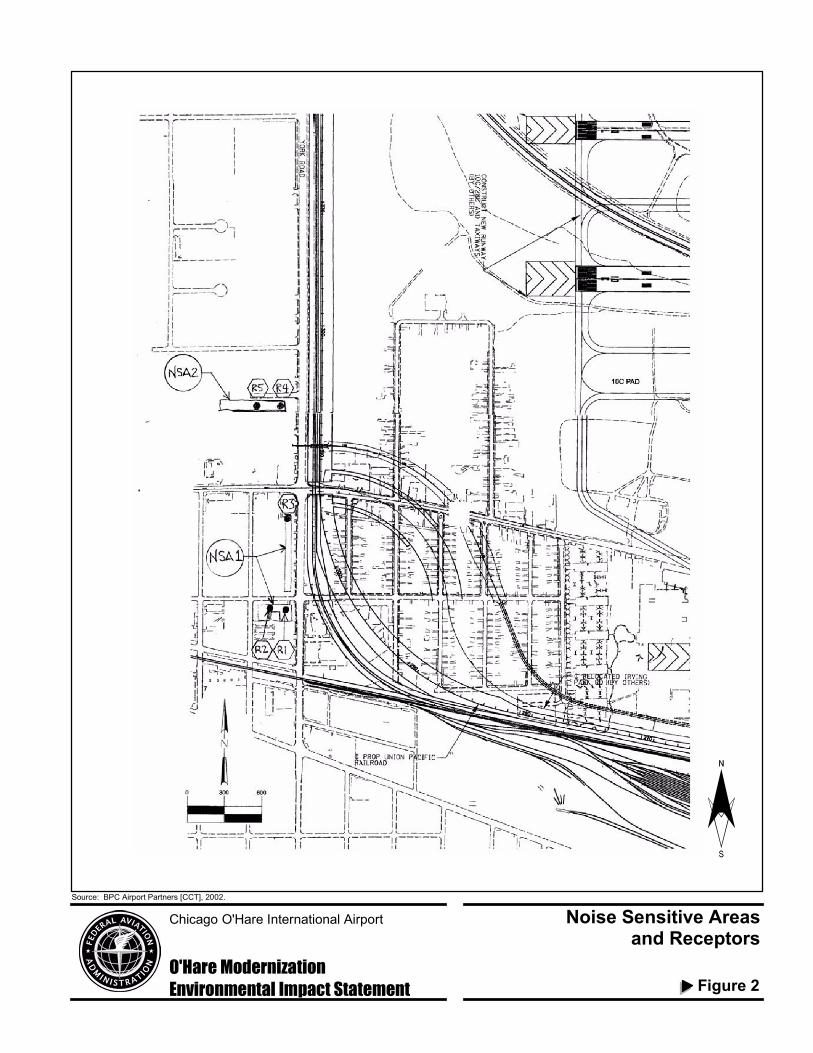
Figure 2
Noise Sensitive Areasand Receptors
Source: BPC Airport Partners [CCT], 2002.
Chicago O'Hare International Airport
Environmental Impact StatementO'Hare Modernization
¨
Page 6
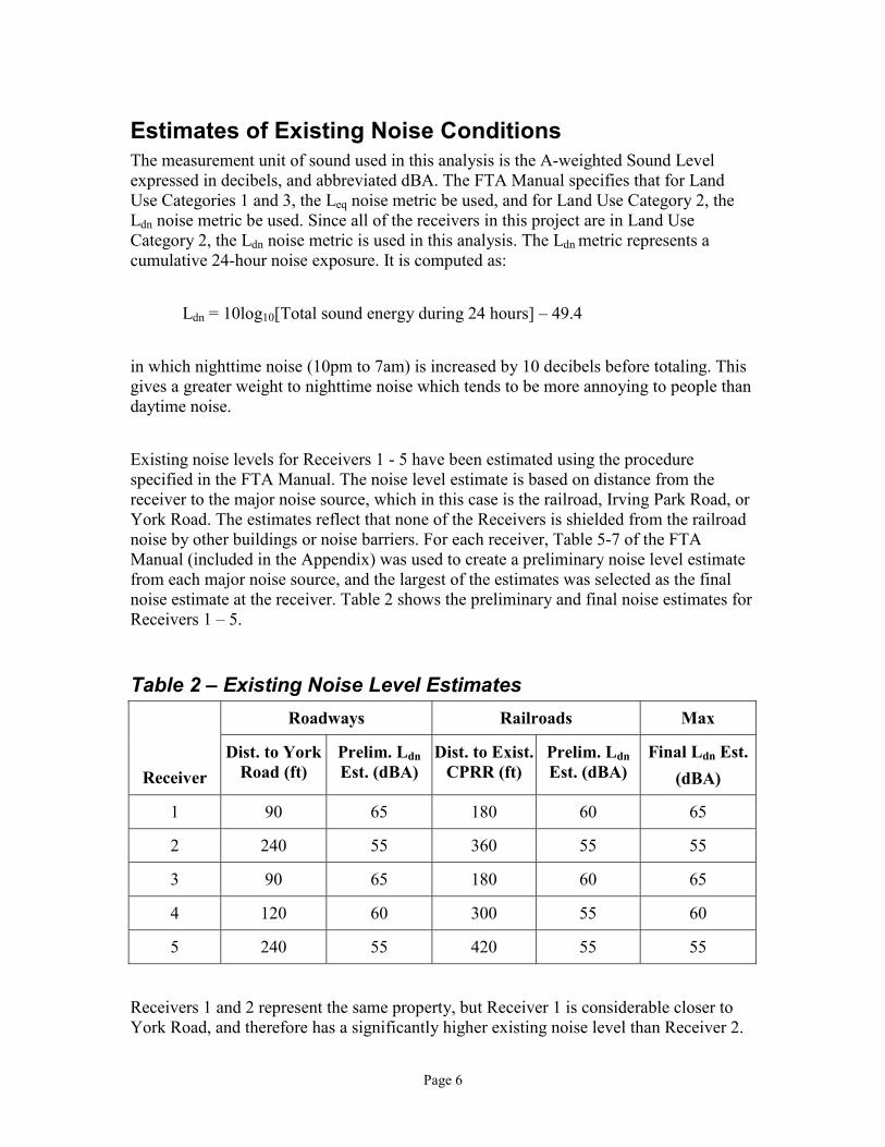
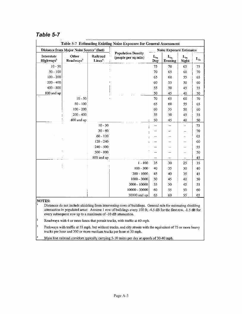
Estimates of Existing Noise Conditions The measurement unit of sound used in this analysis is the A-weighted Sound Level expressed in decibels, and abbreviated dBA. The FTA Manual specifies that for Land Use Categories 1 and 3, the Leq noise metric be used, and for Land Use Category 2, the Ldn noise metric be used. Since all of the receivers in this project are in Land Use Category 2, the Ldn noise metric is used in this analysis. The Ldn metric represents a cumulative 24-hour noise exposure. It is computed as: Ldn = 10log10[Total sound energy during 24 hours] – 49.4 in which nighttime noise (10pm to 7am) is increased by 10 decibels before totaling. This gives a greater weight to nighttime noise which tends to be more annoying to people than daytime noise. Existing noise levels for Receivers 1 - 5 have been estimated using the procedure specified in the FTA Manual. The noise level estimate is based on distance from the receiver to the major noise source, which in this case is the railroad, Irving Park Road, or York Road. The estimates reflect that none of the Receivers is shielded from the railroad noise by other buildings or noise barriers. For each receiver, Table 5-7 of the FTA Manual (included in the Appendix) was used to create a preliminary noise level estimate from each major noise source, and the largest of the estimates was selected as the final noise estimate at the receiver. Table 2 shows the preliminary and final noise estimates for Receivers 1 – 5.
Table 2 – Existing Noise Level Estimates Roadways Railroads Max
Receiver Dist. to York
Road (ft) Prelim. Ldn Est. (dBA)
Dist. to Exist. CPRR (ft)
Prelim. Ldn Est. (dBA)
Final Ldn Est.(dBA)
1 90 65 180 60 65
2 240 55 360 55 55
3 90 65 180 60 65
4 120 60 300 55 60
5 240 55 420 55 55
Receivers 1 and 2 represent the same property, but Receiver 1 is considerable closer to York Road, and therefore has a significantly higher existing noise level than Receiver 2.

Page 7
It should be noted that aircraft noise was not a factor in the existing noise level estimates because the FTA methodology does not include aircraft noise. This is a conservative tactic since the exclusion of aircraft noise makes the existing noise level estimates lower, which reduces the allowable amount of project noise.
Predictions of Project Noise The FTA Manual procedure for predicting railroad project noise is outlined below. Note that the procedure predicts project noise only, not noise from other sources.
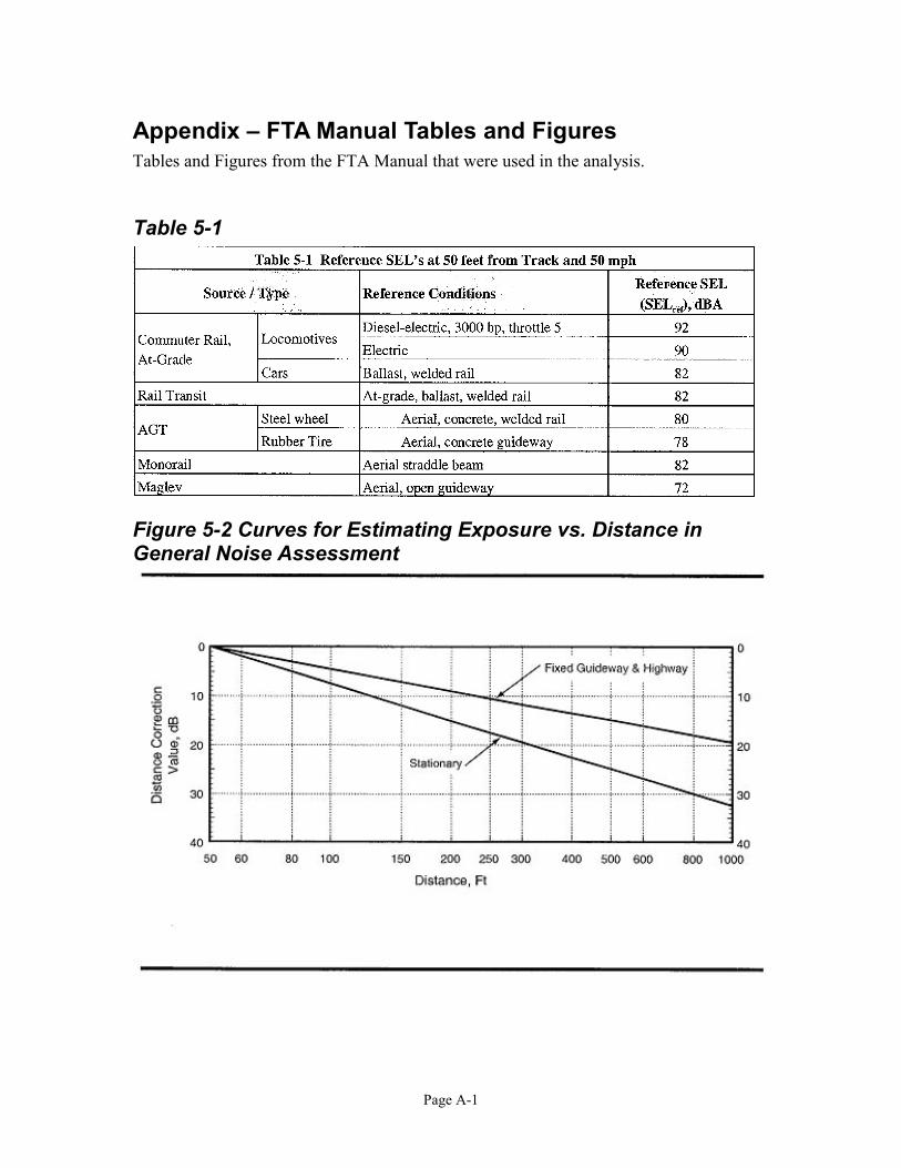
1) Determine the source reference noise levels, in terms of Sound Exposure Levels (SEL), at a given distance and a reference speed. These reference SELs are given in Table 5-1 in the FTA Manual (included in the Appendix).
For this project: The reference SELs for this project given by Table 5-1 are: Locomotive SELref = 92 dBA Rail car SELref = 82 dBA
2) Use the reference SELs to calculate project noise exposure in Ldn at 50 feet using the equations in Table 5-2 of the FTA Manual (included in the Appendix).
For this project: The design year Ldn was calculated using the reference SELs, the equations in Table 5-2, and the following design year project data, which has been provided by Union Pacific:
Number of trains daily, daytime (7am – 10pm) = 8 Number of trains daily, nighttime (10 – 7am) = 8 Average number of locomotives per train = 2 Average number of cars per train = 75 Maximum train speed (mph) = 20 – 30
Result: Ldn = 69.9 dBA
3) Use the Ldn at 50 feet and the appropriate Distance Correction Values from Figure 5-2 of the FTA manual (included in the Appendix) to create a noise exposure curve as a function of distance.
Page 8
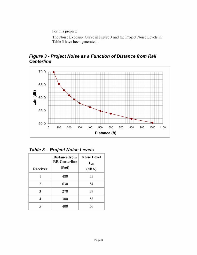
For this project: The Noise Exposure Curve in Figure 3 and the Project Noise Levels in Table 3 have been generated.
Figure 3 - Project Noise as a Function of Distance from Rail Centerline
50.0
55.0
60.0
65.0
70.0
0 100 200 300 400 500 600 700 800 900 1000 1100
Distance (ft)
Ldn
(dB
)
Table 3 – Project Noise Levels
Receiver
Distance from RR Centerline
(feet)
Noise Level Ldn
(dBA)
1 480 55
2 630 54
3 270 59
4 300 58
5 400 56
Page 9
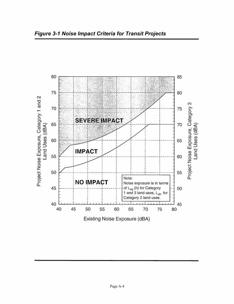
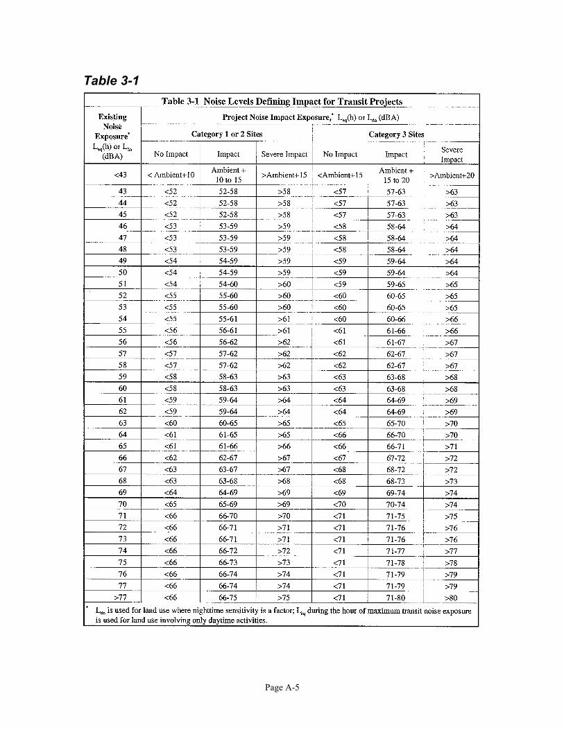
Noise Impact Criteria Rail noise impact criteria are defined in Chapter 3 of the FTA Manual. They are shown graphically in the Manual in Figure 3-1 and are tabulated in Table 3-1, which are included in the Appendix of this report. The foundation of the criteria is a comparison of the existing outdoor noise levels and the projected future outdoor noise levels due to the proposed project. They consider both the absolute noise levels caused by the project, and the changes to the noise environment caused by the project. Noise impacts are identified using either Figure 3-1 or Table 3-1 together with the existing noise exposure and the project noise exposure. Noise impacts are based on the number of people that would be expected to be highly annoyed by the project noise. In the No Impact range, the project noise is not likely to cause an increase in the number of people highly annoyed by the new noise. The Severe Impact level represents the level at which a significant percentage of people would be highly annoyed by the new noise. The Impact range in between represents levels that most people would notice as an increase, but may not be high enough to cause strong negative reactions.
Noise Impact Assessment Noise impacts have been determined using the noise criteria with the estimated existing noise and predicted project noise. The results are summarized in Table 4 and indicate that Receivers 4 and 5 are expected to experience noise impacts.
Table 4 – Project Noise Impacts
Receiver
Estimated Existing Ldn
(dBA)
Impact Level (dBA)
Severe Impact
Level (dBA)
Project Noise
Ldn (dBA) Impact
1 65 61 66 55 None
2 55 56 61 54 None
3 65 61 66 59 None
4 60 58 63 58 Impact
5 55 56 61 56 Impact
Project noise levels Receivers 4 and 5 are barely in the Impact range. At Receiver 4, the project noise level is 2 dBA lower than the existing level. As discussed earlier, these results are somewhat conservative because the existing noise level estimates do not include aircraft noise, which reduces the allowable amount of project noise. The identified impacts are based on the conceptual railroad plans listed in
Page 10
the references. If the proposed railroad geometry changes significantly, the railroad noise should be reanalyzed.
Noise Mitigation At sites with identified impacts, the FTA process calls for the project sponsor to consider noise reduction measures if they are reasonable: first in the form of alternative project locations or alignments, and second in the form of noise mitigation. The relocation of the UPRR tracks is required for the expansion of the airport, and the relocated tracks have been located in relation to a proposed runway and other improvements in the southwestern part of the airport. Changing the location or alignment of the proposed relocated UPRR tracks would have complex repercussions on the project and should be avoided if possible. The goal of noise mitigation efforts is to reduce noise by a substantial amount, not to simply reduce the noise levels to below the severe impact threshold. Noise mitigation can occur at three locations: 1) at the noise source, 2) along the path between the source and the receiver, or 3) at the receiver.
1) Mitigation measures at the noise source generally involve the tracks or rail car equipment. The track measures include avoiding sharp curves with radii less than 1000 feet, and eliminating corrugated rail and unnecessary joints, which are already being met by this project. The rail car measures are practical in situations in which a relatively small number of rail cars are used, and don’t apply well to this project.
2) Path mitigation measures involve features that reflect or absorb sound as it travels
from the source to the receiver, such as noise barriers or buffer zones. Buffer zones are areas of land between noise sources and receivers that are reserved for non-noise-sensitive uses, that are maintained with sound-absorptive features, such as vegetation. Sound-reflective surfaces such as paving materials or water are poor choices for buffer zones. Sound barriers can be located anywhere along the path between source and receivers, although they are usually most effective when placed close to the source or receiver, not in the middle.
3) Mitigation at the receiver involves “soundproofing” buildings by improving
building insulation or installing sound-insulated windows. These measures can be very effective and they have the benefit of reducing noise from all outside sources, not just one project. However, they obviously do not reduce noise for outdoor settings, such as a backyard.
Page 11
The noise mitigation measures that would be most effective for this project appear to be construction of a noise barrier next to the tracks and soundproofing the receivers. The following paragraphs discuss the two mitigation measures. Construction of a noise barrier next to the tracks can reduce noise levels from the railroad by 6 to 10 dBA and can likely be accomplished without acquiring additional right-of-way. However, for the proposed project, the potential for noise reduction at the Receivers is severely limited by the presence of other significant nearby noise sources, such as York Road, Irving Park Road, Chicago - O’Hare International Airport, and the Canadian Pacific Railroad tracks next to York Road. A barrier next to the UPRR tracks would not reduce the significant noise from these other sources, and likely would not have a very significant effect at the Receivers. Soundproofing the impacted buildings would be a more effective mitigation measure because it would reduce the noise from all sources, not just the UPRR tracks. However, it would not reduce the noise in outdoor settings, such as backyards. According to the O’Hare Community Noise Resource Center website (http://www.ohare.com/images/cnrc/ohare/rsip_2002.jpg), the homes on Brookwood Street near Receivers 4 and 5 are part of the O’Hare Residential Sound Insulation Program, and have either already been insulated against noise, or their owners have declined to participate in the program. These homes are presumably already insulated against current and future rail noise. Given that project noise levels at both of the impacted Receivers are barely in the impact range and that the impacted houses are already part of the O’Hare Residential Sound Insulation Program, we do not recommend mitigation measures for the proposed Relocated UPRR Railroad.
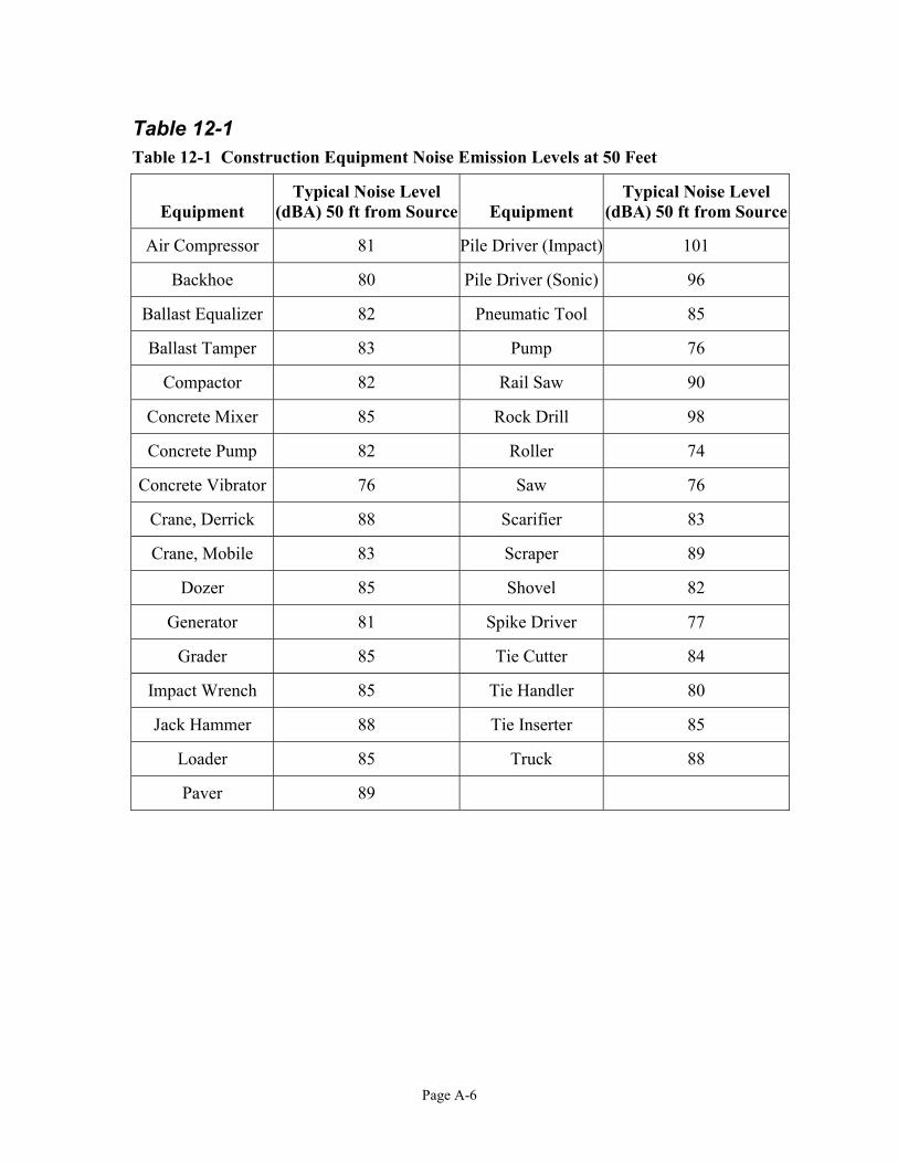
Construction Noise Impacts The major construction elements of this project are expected to be earth removal, hauling, grading, paving, and bridge construction. General construction noise impacts, such as temporary speech interference for passerby and those individuals living or working near the project, can be expected, particularly from earth moving equipment during grading operations, paving operations, and pile driving. Table 12-1 in the Appendix lists some typical peak operating noise levels at a distance of 50 feet. For this project, the Receivers would range from about 200 feet to about 550 feet from the construction, which would lower the construction sound levels by approximately 9 to 15 dBA, according to Figure 5-2. Considering the relatively short-term nature of construction noise, impacts are not expected to be substantial.
Conclusions The conclusion of this General Noise Assessment is that the proposed Relocated UPRR tracks would not severely affect the noise in the project area. The four houses represented by Receivers 4 and 5 would experience impacts, while those represented by Receivers 1, 2, and 3 are not likely to experience noise impacts as defined by the FTA process.

Page 12
Given that project noise levels at both of the impacted Receivers are barely in the impact range and that the four impacted houses are already part of the O’Hare Residential Sound Insulation Program, we do not recommend mitigation measure for the proposed Relocated UPRR Railroad.
References 1. U.S. Department of Transportation, Federal Transit Administration, “Transit
Noise and Vibration Impact Assessment,” Final Report, DOT-T-95-16, April 1995.
2. City of Chicago, Department of Procurement Services, “O’Hare Modernization Program Conceptual Engineering, WA#20 Union Pacific Railroad Relocation,” Conceptual Design Not For Construction, November 2003.
Page A-1
Appendix – FTA Manual Tables and Figures Tables and Figures from the FTA Manual that were used in the analysis.
Table 5-1
Figure 5-2 Curves for Estimating Exposure vs. Distance in General Noise Assessment

Page A-2
Table 5-2
Page A-3
Table 5-7
Page A-4
Figure 3-1 Noise Impact Criteria for Transit Projects
Page A-5
Table 3-1
Page A-6
Table 12-1 Table 12-1 Construction Equipment Noise Emission Levels at 50 Feet
Equipment Typical Noise Level
(dBA) 50 ft from Source Equipment Typical Noise Level
(dBA) 50 ft from Source
Air Compressor 81 Pile Driver (Impact) 101
Backhoe 80 Pile Driver (Sonic) 96
Ballast Equalizer 82 Pneumatic Tool 85
Ballast Tamper 83 Pump 76
Compactor 82 Rail Saw 90
Concrete Mixer 85 Rock Drill 98
Concrete Pump 82 Roller 74
Concrete Vibrator 76 Saw 76
Crane, Derrick 88 Scarifier 83
Crane, Mobile 83 Scraper 89
Dozer 85 Shovel 82
Generator 81 Spike Driver 77
Grader 85 Tie Cutter 84
Impact Wrench 85 Tie Handler 80
Jack Hammer 88 Tie Inserter 85
Loader 85 Truck 88
Paver 89


![Welcome [jdasoc.files.wordpress.com]...Suburban O’Hare Commission Noise Study WORLD CLASS SOC TEAM: 1. Dr. Sanford Fidell 2. Dr. Antonio Trani 3. Dr. David Dubbink 4. Craig Burzych](https://static.fdocuments.net/doc/165x107/603e6d6e59bc35598c2a11ac/welcome-suburban-oahare-commission-noise-study-world-class-soc-team-1.jpg)