
ATTACHMENT C1 MANAGEMENT STRUCTURE AND ORGANISATION CHART · The organisation chart is presented...
30
Q/CE07/253/01/WLA Attachments ANNEX – Standard Forms ATTACHMENT C1 MANAGEMENT STRUCTURE AND ORGANISATION CHART Site Management Structure The day to day management of the facility and supervision of waste activities are the responsibility of the Facility Manager, nominated Deputy Manager(s) and the site operatives. The positions and names of the persons who provide management and supervision are set out below: - • Facility Manager, Michael Murray • Deputy Facility Manager, Daphne Walshe-Deacon • Sales Manager, William Deacon • Yard Manager, John Murray • Drivers, Michael Murray, James Harris, Thomas Guinnan, Karl Sweeney, Russell Burke • Yard Operatives, Mieczyslaw B Leszczynski, Wronowski Przemyslaw, Krzysztof Solak, Roman Stankiewicz, Iveneusz Solak, Piotr Chmiel, Andrew Murray • Administrator, Dawn Porter • Administrative assistant, Jennifer Breen, Karen Kehoe The organisation chart is presented overleaf. For inspection purposes only. Consent of copyright owner required for any other use. EPA Export 26-07-2013:03:50:15
Transcript of ATTACHMENT C1 MANAGEMENT STRUCTURE AND ORGANISATION CHART · The organisation chart is presented...

Q/CE07/253/01/WLA Attachments ANNEX – Standard Forms
ATTACHMENT C1 MANAGEMENT STRUCTURE AND ORGANISATION CHART
Site Management Structure The day to day management of the facility and supervision of waste activities are the responsibility of the Facility Manager, nominated Deputy Manager(s) and the site operatives. The positions and names of the persons who provide management and supervision are set out below: -
• Facility Manager, Michael Murray • Deputy Facility Manager, Daphne Walshe-Deacon • Sales Manager, William Deacon • Yard Manager, John Murray • Drivers, Michael Murray, James Harris, Thomas Guinnan, Karl Sweeney, Russell Burke • Yard Operatives, Mieczyslaw B Leszczynski, Wronowski Przemyslaw, Krzysztof Solak,
Roman Stankiewicz, Iveneusz Solak, Piotr Chmiel, Andrew Murray • Administrator, Dawn Porter • Administrative assistant, Jennifer Breen, Karen Kehoe
The organisation chart is presented overleaf.
For
insp
ectio
n pur
pose
s only
.
Conse
nt of
copy
right
owne
r req
uired
for a
ny ot
her u
se.
EPA Export 26-07-2013:03:50:15

Q/CE07/253/01/WLA Attachments ANNEX – Standard Forms
FIGURE 1 ORGANISATION CHART SHOWING ON-SITE MANAGEMENT STRUCTURE
Facility Manager
Managing Director Mr. Michael Murray
Overall Responsibility ~ Contingency Arrangements ~ Environment
Performance & Protection ~ Day to Day Operations ~ Waste Acceptance
Deputy Facility Manager Office Manager
Ms. Daphne Walshe-Deacon
Deputising for the Facility Manager in his absence ~ Office Management ~
Responsibility for the preparation of all matters pertaining to the waste and
environmental control.
Yard Manager
Mr. John Murray Daily Management of all activities in the yard ~ Management of all loads entering and exiting the
facility ~ Waste Inspection
Lorry Drivers x 4
Driving Skip Loaders ~ Waste
Inspection
Artic Driver X 1
Transporting Material for
further recycling,
recovery and disposal ~
Driving Skip/Hook
Loader when necessary
General Operatives
x 7 Waste
Acceptance & Sorting ~ General
Maintenance
Administrator Weighbridge
Operator
Ms. Dawn Porter Weighing ~ Maintaining
Records ~ Day to day Administration
~ First Aid
Administrative Assistant X 2
Weighing ~ Assisting in the day to day Administration
Sales Manager
Mr. William Deacon Sales Management and cover for the
yard manager.
For
insp
ectio
n pur
pose
s only
.
Conse
nt of
copy
right
owne
r req
uired
for a
ny ot
her u
se.
EPA Export 26-07-2013:03:50:15

Q/CE07/253/01/WLA Attachments ANNEX – Standard Forms
Responsibilities Murray Waste Recycling Ltd is responsible for ensuring that the requisite resources are provided to operate the facility in accordance with the objective of the Environmental Management Plan (EMP) and the Waste Licence conditions.
• The General Manager or nominated Deputy is responsible for ensuring that the day to day operation of the facility is carried out in accordance with the EMP, the Waste Licence conditions and the Operating Procedures.
• The General Manager or nominated Deputy is responsible for ensuring that the environmental monitoring programme is carried out and reports are submitted to the Agency in accordance with the schedule in the EMP and the Waste Licence conditions.
• The General Manager or nominated Deputy is responsible for arranging that the specified engineering works and the restoration programmes are properly implemented.
• The General Manager or nominated Deputy is responsible for ensuring that the Corrective Action Procedures, Emergency Response Procedures and Contingency Arrangements specified in the EMP and the Waste Licence are implemented.
• The General Manager or nominated Deputy is responsible for arranging appropriate training programmes for all facility personnel and for maintaining training records.
• The General Manager, nominated Deputy and designated staff are responsible for implementing the waste acceptance procedures, including the assessment of suitability of the waste for disposal and recording the data specified in the Waste Licence. They are responsible for receiving and recording complaints from members of the public at the facility and informing the Facility Manager or nominated Deputy of the complaints.
• The General Manager, nominated Deputy, Yard Manager and designated staff are responsible for ensuring compliance with conditions relating to waste inspection, placement and nuisance control (e.g. litter, dust, vermin and birds).
Staff Training Any facility staff performing duties which involve interpretation of monitoring results or site inspections receive the appropriate training by the General Manager or nominated deputy, prior to carrying out such duties. All facility staff will receive further training in their individual areas of activity. This training will comprise theoretical sessions as well as practical training. All such training will be recorded and documented in individual training files.
For
insp
ectio
n pur
pose
s only
.
Conse
nt of
copy
right
owne
r req
uired
for a
ny ot
her u
se.
EPA Export 26-07-2013:03:50:15

Q/CE07/253/01/WLA Attachments ANNEX – Standard Forms
ATTACHMENT C2 ENVIRONMENTAL MANAGEMENT SYSTEM (EMS)
The Environmental Management System was prepared in accordance with the requirements of the waste permit and based on ISO 14001. This system is not externally accredited. A copy of the EMS will be submitted in accordance with the waste licence.
For
insp
ectio
n pur
pose
s only
.
Conse
nt of
copy
right
owne
r req
uired
for a
ny ot
her u
se.
EPA Export 26-07-2013:03:50:15

Q/CE07/253/01/WLA Attachments ANNEX – Standard Forms
ATTACHMENT C3 HOURS OF OPERATION
(a) Proposed hours of operation
The proposed hours for waste management operations are
• 06:30 to 21:00, Monday to Saturday and Bank Holidays
(b) Proposed hours of waste acceptance/handling The proposed hours for waste acceptance are
• 07:30 to 20:00, Monday to Saturday and Bank holidays
(c) Proposed hours of any construction and development works at the facility and timeframes
The proposed hours for construction/maintenance operations are:
• 07:00 to 20:00, Monday to Friday • 07:30 to 18:00, Saturday
(d) Any other relevant hours of operation expected Not applicable
For
insp
ectio
n pur
pose
s only
.
Conse
nt of
copy
right
owne
r req
uired
for a
ny ot
her u
se.
EPA Export 26-07-2013:03:50:15

Q/CE07/253/01/WLA Attachments ANNEX – Standard Forms
ATTACHMENT D1 INFRASTRUCTURE
D.1.a Facility Security Arrangements The facility operation can be seen in Drawing CE07-253-01_206 which illustrates the layout of the site. Access to the facility will be restricted by means of existing gates and constructed 1 m stone wall. An additional second set of gates is set approximately 70 m back from the site boundary. The height of the stone wall and gates at this entrance is approximately 2.5 m. The recycling building will remain secured when the facility is unsupervised. Palladin fencing or similar will be used around the southern and western boundaries as shown in Drawing CE07-253-01_206. This fencing will tie in to the existing boundary fence where applicable, making the site secure. The existing boundary fence consists of stone embankment with mature hedgerow and trees. An existing chain link runs between the dwelling and the facility in the northeast corner of the site. Any defect in the gates and/or fencing shall be temporarily repaired by the end of the working day and reinstated fully within one week. Site infrastructure is shown in Drawing CE07-253-01_206. D.1.b Site roads The site is located approximately 2 km south east of Ferns via the R745. The facility office and recycling building is accessed via a concrete road with surface water draining to oil/water interceptor gullies on the roadway. The area outside the recycling building is currently hardcore, however it is planned to concrete this area upon completion of an extension to the recycling building as shown in Drawing CE07-253-01_206. D.1.c Specifications of Hard Standing Areas The concrete hard standing area runs from the main gate to the recycling building. The area to front of the recycling building is currently hardcore, which stores empty waste skips. It is planned that this area and the area reserved for C&D recovery will be finished with concrete with provision for surface water drainage to the full oil/water interceptor on site. D.1.d Plant The plant at the site will consist of the following: - Computerised Weighbridge An electronically controlled weighbridge is installed at the facility. It is 18.0 metre in length and is controlled by Enterprise-Advanced Weighbridge software. Trommel Viper (40’ x 10’) trommel and 4 bay picking station Trailers 1 no. ejector trailer (BMI 110 cubic yard - BD10025) Loading Shovel 1 no. Volvo L90 loading shovel 1 no Atlas 1705 Rubber duck with sorting grab Excavator 1 no. Hitachi EX200 360 degree excavator and 2 x JCB backhoe excavator
For
insp
ectio
n pur
pose
s only
.
Conse
nt of
copy
right
owne
r req
uired
for a
ny ot
her u
se.
EPA Export 26-07-2013:03:50:15

Q/CE07/253/01/WLA Attachments ANNEX – Standard Forms
Skip Lorries 4 no. skip lorries and 2 no roll on/off lorries (MERC 1823, IVECO 180E24, DAF FA55, DAF 85, VOLVO FM 9, HINO 700) Tractor 1 no articulated tractor unit (Volvo FM 12 (6 x 4)) Timber shredder 2 no timber shredders Baler 1 no. Gradeall 600 horizontal baler Fork lift 1 no. fork lift truck Road Cleansing 1 no. road sweeper Mobile Concrete Crusher and Screener On an intermittent basis, 1 no. Terex Mobile Jaw Crusher and Screener (or similar) D.1.e Wheel Cleaner There is no wheel wash installed at the facility. It is not proposed to install a wheel wash. All HGV’s entering and exiting the site traverse on concrete hard standing. In addition there is a considerable length of concrete road within the site that allows for detritus matter to fall from the HGV wheels. D.1.f Laboratory Facilities There are no laboratory facilities on site. D.1.g Fuel Storage The following quantity of fuels is stored on site: Derv (Road Diesel) 15,000 litres Marked Gas (Agri Diesel) 10,000 litres Diesel Additive AdBlue 1,000 litres Kerosene 1,000 litres With the exception of the kerosene tank, which is used for heating the administration building, all fuels are stored in a concrete bunded area, located to the rear of the recycling building. Fuel dispensing pumps and nozzles are located within the concrete bund wall. The location of the bunded area is shown in Drawing CE0725301_206. D.1.h Waste Quarantine Area A waste quarantine area has been designated in the current recycling building. The location of the waste quarantine area is shown in the site layout plan.
For
insp
ectio
n pur
pose
s only
.
Conse
nt of
copy
right
owne
r req
uired
for a
ny ot
her u
se.
EPA Export 26-07-2013:03:50:15

Q/CE07/253/01/WLA Attachments ANNEX – Standard Forms
D.1.i Waste Inspection Area Waste characterisation and inspection is conducted in accordance with the Waste Acceptance Procedures (January 2009), contained in Attachment H of the application. D.1.j Traffic Control All traffic entering the site will be from the local road R745. The location of the site entrance is clearly shown by the Murray Waste Recycling sign which was erected in accordance with the waste permit. An automatic barrier is provided for allowing access onto and off the weighbridge. Parking is provided for adjacent to the site office and caters for approximately 20 no. vehicles. It is envisaged that future developments at the site may also consist of a civic amenity facility at the site. An area has been reserved for such a facility to the north end of the site. D.1.k Surface Water Drainage and Sewerage Infrastructure Prior to discharge of rain water from the roof, the water from the existing roof will keep the fire water retention supply tank topped up. The roof water and the overflow from the fire water supply tank will discharge to the stream. Surface water generated from concrete hardstanding areas of the site drain to surface water gullies from the road way to a full oil/water interceptor at the western boundary of the site, prior to discharge to the stream. Details of this oil water interceptor are attached overleaf. Foul water is generated from the onsite toilets and canteen in the administration building. This foul water firstly settles out in a sludge settlement tank adjacent to the site office. The effluent from this settlement tank discharges to an oil water interceptor at the western end of the site and this effluent discharges to Bio-Crete Wastewater and Sewage Treatment System. The effluent from the WWTP discharges to a raised percolation bed. Details of this system are provided overleaf. It is intended to install an underground effluent holding tank for any leachate emanating from the waste and from wash down water used for cleaning the floor of the recycling building. The effluent tank will be capable of holding approximately 6,000 litres of effluent. The effluent (emanating from inside the recycling building) will be sent off site to a WWTP. The WWTP for the treating of the leachate will be agreed in advance with the Agency. The location of the drainage network and wastewater treatment system is shown in Drawings CE07-253-01-205 (existing) and CE07-253-01-206. D.1.l All Other Services Site services are shown in Drawing CE0725301_205. Electricity is mains supplied. On site water is from an onsite groundwater well located in a shed near the main entrance as shown in Drawing CE0725301_206. The site has telephone and broadband connection.
For
insp
ectio
n pur
pose
s only
.
Conse
nt of
copy
right
owne
r req
uired
for a
ny ot
her u
se.
EPA Export 26-07-2013:03:50:16

For
insp
ectio
n pur
pose
s only
.
Conse
nt of
copy
right
owne
r req
uired
for a
ny ot
her u
se.
EPA Export 26-07-2013:03:50:16
lizy
Text Box
Figure 2: Details of Surface Water Oil/Water Interceptor

For
insp
ectio
n pur
pose
s only
.
Conse
nt of
copy
right
owne
r req
uired
for a
ny ot
her u
se.
EPA Export 26-07-2013:03:50:16
lizy
Text Box
Figure 3: Details of Foul Line Treatment System

IRISHAGRÉMENT
BOARDBUILDING PRODUCT CERTIFICATION
CERTIFICATE No. 01/0120
(52.3)
Cl/SfB
Bio-Crete, Delaney Concrete Limited, Clonroche, Co. Wexford, Ireland.Tel: 053 9244767 Fax: 053 9244764
e-mail: [email protected]
Bio-Crete Wastewater & SewageTreatment System
Systémes de Traitement des Eaux Résiduaires. Abwasser Aufbereitung
Readers are advised to check that this Certificate has not been withdrawn or superseded by a later issue by contacting:Irish Agrément Board, NSAI, Glasnevin, Dublin 9
The Irish Agrément Board is designated by Government to issue European Technical Approvals.
Irish Agrément Board Certificates establish proof that the certified products are ‘proper materials’ suitable for their intended use under Irish site conditions, and in accordance with the Building Regulations 1997 to 2000.
The Irish Agrément Board operates in association withthe National Standards Authority of Ireland (NSAI) as the National Member of UEAtc.
PRODUCT DESCRIPTIONThe Bio-Crete Wastewater & Sewage Treatment Systemfor Single Dwellings is a combined aerobic/anaerobicsystem to serve a population equivalent of up to 10persons. It is manufactured from a nylon fibre reinforcedconcrete, is rectangular in shape and has five operatingzones. It is designed to treat all liquid wastewater fromthe household (bathroom toilet, kitchen and laundry).After treatment the clear liquid is discharged by gravityto a percolation area or pumped if a raised bedpercolation system is required.
MANUFACTURE AND MARKETINGThe product is manufactured and marketed by:
Bio-CreteDelaney Concrete LimitedClonrocheCo. Wexford, Ireland.Tel: (053) 9244767 Fax: (053) 9244764
USEThe product is for use in sewage treatment systems andfor sewage collection systems designed in accordancewith BS 6297: 1983 Code of practice for design andinstallat ion of small sewage treatment works andcesspools, for the collection of domestic sewage.
For
insp
ectio
n pur
pose
s only
.
Conse
nt of
copy
right
owne
r req
uired
for a
ny ot
her u
se.
EPA Export 26-07-2013:03:50:16

1.1 ASSESSMENTIn the opinion of the Irish Agrément Board (lAB), Bio-Crete Wastewater & Sewage Treatment System forSingle Dwellings is satisfactory for the purpose definedabove, and meets the requirements of the BuildingRegulations 1997 to 2000 as indicated in Section 1.2 ofthis Certificate.
1.2 BUILDING REGULATIONS 1997 to 2000
Requirement:
PART D - MATERIALS AND WORKMANSHIP.
D3 – Bio-Crete Wastewater & Sewage TreatmentSystem for Single Dwellings as certified in this lrishAgrément Board Certificate, is composed of "propermaterials" and is fit for its intended use (see Part 4 ofthis Certificate).D1 – Bio-Crete Wastewater & Sewage TreatmentSystem for Single Dwellings, used in accordance withthis Irish Agrément Board Certificate, meets therequirements for materials and workmanship.
PART H - DRAINAGE AND WASTE DISPOSAL
H1 Drainage Systems:The Bio-Crete Wastewater & Sewage Treatment Systemfor Single Dwellings is easily installed and incorporatedwith soil percolation to meet Building Regulationrequirements.
H2 Septic Tanks:The Bio-Crete Wastewater & Sewage Treatment Systemfor Single Dwell ings has been designed for use inwastewater treatment systems, for the collection andtreatment of domestic wastewater when installed inaccordance with the recommendations of BS 6297:1983:Code of practice for design and installation of smallsewage treatment works and cesspools and the EPAwastewater treatment manual –Treatment Systems forSingle Houses.
The quality of treated wastewater from Bio-CreteWastewater & Sewage Treatment System for SingleDwellings exceeds that of the eff luent from a septictank and wil l meet the Building Regulationrequirements.
Information on the design capacity, ventilation, safetyand location requirements is given in this IrishAgrément Certificate (see sections 2.4, 3.2 and 4.6 ofthis certificate). The Bio-Crete Wastewater & SewageTreatment System for Single Dwellings can be used indomestic situations where septic tank systems are notacceptable, where sites do not comply with therecommendations of S.R.6. 1991 Septic Tank SystemsRecommendations for Domestic Effluent Treatment andDisposal from a Single Dwelling House and/or whereseptic tank systems have been known to fail.
TECHNICAL SPECIFICATION AND CONTROL DATA
PAR
T
2.1 DESCRIPTIONThe Bio-Crete Wastewater & Sewage Treatment Systemfor Single Dwellings is a combined aerobic/anaerobicsystem to serve a population equivalent of up to 10persons. It is manufactured from a nylon fibre reinforcedconcrete, rectangular in shape, has a low profile designand has five operating zones. It is designed to treat allliquid wastewater from the household (bathroom, toilet,kitchen and laundry). After treatment the clear liquid isdischarged to a percolation area either by gravity orpumping.
The inlet and outlet pipes are 110mm diameter and theinternal pipework system is constructed from 19mmdiameter PVC-U except for the air supply for the sludgereturn which is a 10mm flexible pipe. The air blower isfitted in a chamber which is attached to the concretecover of the system. The control unit for the system islocated in the dwelling being served by the system.
Table 1. Bio-Crete Wastewater Treatment System— basic information
Capacity (litres) Total 4900
Primary Tank (litres) 2600
Aeration (twin zone) litres 1080
Clarifier (litres) 1040
Population served 10
Weight (kg) 4930
Inlet invert pipe depth ± 80 mm on entry ofsewer pipe
Tank bottom 1580 mm below invert
Outlet pipe depth below 50 mminvert of inlet
Overall width (mm) 1200
Overall length (mm) 3400
Overall height (mm) 1930
Discharge pump rating (required 300Wfor raised percolation only)
2
CERTIFICATIONPA
RT 1
For
insp
ectio
n pur
pose
s only
.
Conse
nt of
copy
right
owne
r req
uired
for a
ny ot
her u
se.
EPA Export 26-07-2013:03:50:16

Figure 1:Schematic layout of theBio-Crete WastewaterTreatment System.
Ancillary Items:Pre assembled plumbingAirpumpDiffusersMedialn-house control unitDistribution BoxSump pump (required for raised percolation bed only)Air hoseSealantsSS AnchorsSS Hose clipsConnections and internal tee’sPVC-U inlet and outlet socketsPVC-U underground drain pipes and fittingsDistribution chamberConnection to vitrified clay pipes (where required)Connections and ventilating pipes
The waste treatment is carried out in five stages in thevarious sections of the system as follows:
Section 1 is a septic settlement and sludge storagezone where normal anaerobic reduction in biochemicaloxygen demand (BOD) takes place. It is fitted withbaffles and a scum board.Section 2 is an active biological aeration zone fortreatment of residual solids and further reduction inBOD.Section 3 is a further active biological aeration zonewhich effects nitrification and the conversion ofammonia to nitrate. Oxygen is fed to Sections 2 and 3using fine bubble diffusers.Section 4 is a clarification zone where the convertedactivated sludge/solids are allowed to settle out and theclear liquid discharged. The settled activated sludge iscontinual ly re-circulated by airl ift to the primarychamber.Section 5 is an anoxic zone designed to encouragedenitrification by heterothopic bacteria. Disposal to theirrigation system is normally by gravity but may also bepumped where this is deemed necessary.
The Bio-Crete Wastewater Treatment System isdesigned for below ground installation and the tank issupplied with removable covers to permit inspectionand maintenance. A schematic layout of the system isshown in figure 1.
The system is supplied with f loat switch operatedalarms that indicate both pump failure and high waterlevel.
2.2 MANUFACTURE
The Bio-Crete tank unit is rectangular in shape and ismanufactured in a single pour from nylon fibrereinforced concrete and the cover is manufactured fromconventional reinforced concrete. When the tank iscured the divider walls are inserted, chemically sealedand mechanically anchored. All plumbing joints aremechanically abraded and solvent sealed. Pre jig cutmedia are assembled at the works and the cover fittedand sealed. The air pump is fitted in the cover with itsair hoses and stainless steel hose clips. The concretetank is checked by visual inspection and the plumbingassemblies are l ive tested under working pressurebefore installation in the tank.
Quality ControlQuality control includes industry standard cube testing,wall thickness checks on concrete components, and thechecking of bought-in components against specifica-tion. Each completed unit is inspected before delivery.
2.3 DELIVERY, STORAGE AND MARKING
The tanks are completed ready for del ivery at themanufacturer’s works. The Bio-Crete WastewaterTreatment System must be lifted with slings at thepoints recommended by the manufacturer. Off-loadingmust be carefully supervised using chains, steel cablesor l ifting bars rated in excess of 5 tonnes. Liftingequipment should be selected by taking into accountthe unit weight, dimensions and the distance of liftrequired. The weight of each unit empty is given in
For
insp
ectio
n pur
pose
s only
.
Conse
nt of
copy
right
owne
r req
uired
for a
ny ot
her u
se.
EPA Export 26-07-2013:03:50:16

Table 1 and should conform with the requirements ofthe Safety Health and Welfare at Work Act, 1989. Themanufacturer’s instructions must be followed to avoiddamage to the tanks during off-loading and placing inthe excavation. A crane or other suitable l iftingequipment must be employed. It is the manufacturer’spolicy to deliver and install each unit using factorytransport complete with a lifting crane.
The product bears the manufacturer’s name, labelsdenoting the inlet and outlet, a list of all the itemssupplied, installation and operating instructions, theproduct specification code, serial number and theinspection date. An external label indicates the lABidentification mark incorporating the certificate number.
2.4 INSTALLATION PROCEDURE
2.4.1 GENERALDelaney Concrete Limited provide a service for thedesign, site survey and instal lation of Bio-CreteWastewater Treatment System units. They will alsoadvise cl ients of the instal lation requirements, orprovide supervision of instal lations carried out byothers.
Electrical connections to the Bio-Crete WastewaterTreatment System from the control box must be carriedout by a competent qualified person using materialsuitable for the purpose.
Electrical connections must be in strict accordance withthe manufacturers instructions and must comply withThe National Rules For Electrical lnstallations (ETCI),published by the ‘Electro-Technical Council of Ireland(Document No. ET101 : 2000).
The electrical control panel is located in the dwellingserved by the unit. However, electric cables to the unitmust be protected from accidental damage by a suitableconduit or other means of protection.
The Bio-Crete Wastewater Treatment System must notbe installed in areas liable to localised flooding withoutadequate protection as specified by the manufacturers.
Also storm water drainage from the dwelling must beexcluded from the unit.
It is essential to take precautions to prevent damage bysite traffic.
Superimposed loads from vehicles etc. should not bepermitted within a distance equal to the depth ofexcavation, unless suitable structural reinforcement isprovided. A suitable fence should be erected to preventvehicles and farm animals from approaching too closeto the unit.
The Bio-Crete Wastewater Treatment Unit may beinstalled buried up to 2m below ground level (modularrisers are available when the unit is installed at depthsbelow 1m). The excavation must be large enough foreasy placement of the unit, to permit subsequentbackfil l ing and to allow timbering and sheeting asrequired to meet The Safety, Health and Welfare at WorkAct, 1989.
The units may be bedded on firm excavated ground orwhere necessary onto concrete, which is haunched up
around the base of the unit. The concrete must be ofsufficient thickness (minimum 150mm) and grade 25Nto ensure that the unit is adequately supported withdue regard to sub-soil conditions and loads imposed bythe Bio-Crete Wastewater Treatment System when full.(Care must be taken to eliminate voids). All water andboulders must be removed from the excavation beforeinstallation of the unit. When installed the top flangemust be level .
The backfill must be carefully consolidated around theBio-Crete unit with all large stones/boulders removed toensure even transfer of ground loads and to preventlocalised stress concentrations. The Bio-CreteWastewater Treatment System should be ballastedwhile backfilling with water keeping the water level justabove the backfill level as work progresses.
Pipe ConnectionsThe tank is connected to 110mm PVC-U pipes asrequired at the inlet and outlet. For other types of pipesuch as vitrified clayware etc. suitable adapters areused with short lengths of PVC-U pipe as necessary. Ashort length of pipe with flexible joints must be usedadjacent to the Bio-Crete Wastewater TreatmentSystem, to allow for differential movement between thetank unit and adjacent pipe runs.
2.4.2 LOCATIONThe Bio-Crete Wastewater Treatment System locationshould be chosen so that adequate access is availablefor site installation and subsequent maintenance anddesludging of the unit. Desludging should be carriedout by means of a desludging tanker which requiresaccess to within 10m of the unit, whilst maintainingappropriate separation distances from the Bio-CreteWastewater Treatment System unit and the eff luentpercolation system given in Table 2. Ventilation must beprovided in accordance with the Building Regulations1997 to 2000.
2.4.3 TREATED WASTEWATER DISPOSAL
General PrinciplesThe Bio-Crete Wastewater Sewage Treatment Systemfor single dwell ings produces treated water, (BOD20mg/l, suspended solids < 30mg/l), which is moreeasily absorbed into soil strata than septic tank effluent.
Figure 2: Showing a cross-sectionthrough a percolation trench.
For
insp
ectio
n pur
pose
s only
.
Conse
nt of
copy
right
owne
r req
uired
for a
ny ot
her u
se.
EPA Export 26-07-2013:03:50:16

Estimated maximum number Required length of trench Required length of trenchof people in the house based in (m) for “T” values 21-50* in (m) for “T” values 5-20††
on number of bedrooms (loading at 25 l/m2.d) (loading at 50 l/m2.d)
(2 persons per bedroom) Trench width Trench width
450mm 1m 450mm 1m
4 64 29 32 14
6 96 43 48 22
8 128 58 64 29
10 160 72 80 36
Table 3: Guidance for sizing of percolation area (in linear metres of percolation pipe)
The choice of disposal method wil l be largelydetermined by the percolation characteristics of the sitesoil which can be quantified by various criteria notablythe “T” value resulting from a percolation test, as setout in SR6: 1991.
There are three possible methods for disposal of thetreated wastewater
a) Sub-Surface percolation, orb) Raised percolation bed, orc) Discharge to surface water, either directly or
fol lowing a polishing filter. (A licence must beobtained from the relevant local authority if thisoption is chosen).
In the event of the site failing the “T” test it may benecessary to construct a raised percolation area.
In any event a site suitability report including a detailedvisual inspection of the site, inspection of a trial hole forsoil profile, depth of water table, and percolation value,should be carried out together with local knowledge as
appropriate. This report should be used to ascertain thesize and type of percolation area required.
The results of this assessment will enable the selectionof the most suitable method for disposing of the finaltreated effluent, having regard to soil type, percolationcharacteristics, water table level and other factors. Thedisposal method wil l be either to sub-surfacepercolation, raised percolation area or direct to surfacewaters by licence. This licence should be obtained fromthe relevant local authority. Reference should also bemade to the following publications:
(a) Wastewater Treatment Manual – Treatment Systemsfor Single Houses published by the EPA.
(b) Ground Water Protection Responses for On-SiteWastewater Systems for Single Houses published byEPA/DOELG/GSI (2001).
Guidance for sizing of the percolation area is set out inTable 3. Treated wastewater is discharged from the Bio-Crete Wastewater Treatment System by gravity or bypumping if a raised bed facility is required.
(a) Sub-surface percolationWhere sub-surface irrigation is to be used the extent ofthe treated wastewater disposal area will be based onthe results of percolation tests.
The treated wastewater discharges, by gravity, into anetwork of perforated 110mm diameter pipes laid instone fi l led trenches (see Fig. 2 and Fig. 3). Theobjective is to spread the treated wastewater as evenlyas possible over the required land area, thus minimisingthe possibility of the ground becoming over-saturated.
The discharge from the Bio-Crete WastewaterTreatment System has minimal suspended solids and is,therefore, much more readily absorbed than septic tankeff luent. The extent of the irrigation system may bedetermined by the site assessment, taking into accountthe soil type and percolation test results, as well as thepopulation to be served. The values listed in Table 3are given for guidance only, the layout and size of thepercolation area should be established on the basis of theresults of a site survey carried out by a competent person.
The percolation area will be equivalent to the linearpipe length as shown in Table 3.
Trenches are generally 450-1000mm wide with the pipeslaid on 250mm of clean 15-25mm stone and coveredwith a polyethylene or geo-textile soil barrier. Layout of
(1) The depth of excavation to accommodate the Bio-Crete Unit must betaken into account when determining this distance. The separationdistance should be such that the excavation does not undermine adjacentbuildings, roads or walls. This distance should be not less than 1.5 timesthe excavation depth.
(2) The separation distance should be not less than 30 metres except inthe case of very free draining soils or gravels, where a minimum distanceof 40 metres should be maintained. The irrigation area should be downhill of any nearby well. Where this is not possible, a separation distanceof at least 100 metres must be maintained.
(3) These are minimum permissible distances. However, where the sitepermits, irrigation areas should be located at greater distances from thedwelling. Also where practicable on sloping sites the irrigation areashould slope from the dwelling.
FEATURE MINIMUM SEPARATION (m)
Bio-Crete Irrigation Area
Dwelling served 7(1) 10(3)
Adjacent dwelling 7(1) 10(3)
WaIl 3(1) 3
Road 4(1) 4
Site boundary 3(1) 3
Potable water source 10 30—100(2)
Watercourse 10 10
Table 2
†† For percolation values “T” <5
* For percolation values “T” >50 } consult the manufacturer for details of the percolation area required.
For
insp
ectio
n pur
pose
s only
.
Conse
nt of
copy
right
owne
r req
uired
for a
ny ot
her u
se.
EPA Export 26-07-2013:03:50:16

the trenches will be determined by site topography, theoverall fall of the pipes should be not more than 1 in200. The pipes should be at least 1 metre above thehighest water table level, fissured rock strata orimpermeable soil layer.
(b) Raised percolation bedWhere the irrigation pipes have to be above existingground level: e.g. thin topsoils and/or rock or watertable close to the surface, a raised or banked-upirrigation system may be suitable. In this situation apumped discharge would be required (see Figure 3).
(c) Discharge to a watercourseWhere poor soil percolation or other factors make asubsurface irrigation system impractical; discharge to awatercourse may be considered. This will require alicence from the relevant local authority, setting theminimum acceptable discharge quality. The treatedwastewater is filtered through a layer of sand or topsoilbefore passing to the watercourse.
Inspection access to all treated wastewater irrigationsystems should be provided at the end of thepercolation system via a suitably constructed inspectionchamber.
Further treatmentIn some instances (e.g. proximity to a drinking watersource), the wastewater may require ‘polishing’ beforedischarge to reduce coliform bacteria levels. Acommonly used method is to pass the dischargethrough a stratified sand fi lter. The Bio-CreteWastewater Treatment System discharge is pumped tothe filter. Polishing filters can be provided on request asan additional item with the system
2.5 COMMISSIONING
Commissioning by a competent person should becarried out after installation and this service is availablefrom the installer or designated service provider.
DESIGN DATA
PAR
T 33.1 GENERAL
The Bio-Crete Wastewater Treatment System is suitablefor the collection and treatment of domestic sewage andshould be instal led in accordance with themanufacturer’s instructions and to conform with therecommendations of BS 6297: 1983 Code of practice forthe design installation of small sewage treatment worksand cesspools. It is important that the loadings arebased on the maximum population to be served.
Bio-Crete Wastewater Treatment System should be sitedin accordance with the relevant Building Regulations.
Ground water and flood levels should always be belowplant outlet level.
The discharge from the Bio-Crete WastewaterTreatment System must be to a suitable sub-soilpercolation system, raised percolation bed, orwatercourse to the requirements of the Local Authority.
The treated wastewater resulting from the sewagetreated by the Bio-Crete Wastewater Treatment Systemwill normally have the characteristics shown in Table 4(i.e. suspended solids content less than 30 mg per litreand Biochemical Oxygen Demand (BOD) less than 20mg per l itre) provided that the hydraulic and BODloadings are within the limits recommended by themanufacturer for the unit installed (180 litres per headper day and 60 grammes per head per day, respectively).Under certain unusual conditions the resultingwastewater may be in excess of this. This is normal forany biological sewage treatment process, and can becaused by unusual hydraulic or BOD loading, weatherconditions, contamination by excessive quantities of (a)offal and grease, (b) household disinfectants, (c)detergents or poisoning of microbiological f lora andfauna by other chemicals.
Figure 3. Section through a banked-uppercolation trench.
For
insp
ectio
n pur
pose
s only
.
Conse
nt of
copy
right
owne
r req
uired
for a
ny ot
her u
se.
EPA Export 26-07-2013:03:50:16

TECHNICAL INVESTIGATIONS
PAR
T 4
3.2 DESIGN BASIS
The relevant dimensions and capacities of the Bio-CreteWastewater Treatment system covered by this IrishAgrément Board certificate are shown in Table 1.
System Alarm – Water levelAll units are fitted with a warning device, connected toan alarm. This alarm system will be activated by apower surge, power failure or high water level withinthe unit.
A short period of acclimatisation must be allowed aftercommissioning of the unit before a full level of treat-ment can be expected. This period is generally a fewweeks and is normal for any biological treatment plant.
3.2.1 WASTEWATER QUALITY
Table 4: Treated wastewater characteristics:
Standard
pH 6 - 9
Biochemical Oxygen Demand <20 mg/l
Suspended Solids <30 mg/I
Ammonia <10 mg/IN
Total Phosphorus 5mg/lP *
E. coli (by soil treatment or disinfection)
4.1 ENVIRONMENTAL ASSESSMENTThe treated wastewater from a number of workinginstallations has been comprehensively monitored for 12months. The test results show that values stated for theparameters listed in Table 4 are consistently achievableover a range of operating conditions.
4.2 STRENGTHThe manufacturer’s design has been assessed assatisfactory. The tank has adequate resistance towithstand impacts during handling and placing andshould prove satisfactory when installed in accordancewith this Certificate. The manhole covers are suitablefor pedestrian traffic.
4.3 LIQUID WATER PENETRATIONThe tank with its pipe connections, when correctlyinstal led, has been assessed as ful ly capable ofpreventing seepage either into or from the surroundingsoil. The pipe joints, when correctly made, wil l bewatertight.
4.4 DURABILITYThe Bio-Crete Wastewater Treatment System wheninstalled, used and maintained in accordance with therequirements of this Irish Agrément Board Certificate,will have a life in excess of 60 years in normal soilconditions. Sites with aggressive soil conditions such aslandfill sites or sulphate bearing soils will require anappropriate cement type and content, reinforcementtype and concrete strength as specified by themanufacturer.
4.5 CLEANING AND MAINTENANCECleaning and maintenance should be carried out inaccordance with the Operation and MaintenanceInstructions supplied by Delaney Concrete Ltd. Themanufacturers also provides a maintenance contract.
Summary of maintenance instructionsThe Bio-Crete Wastewater Treatment System is desludgedby a suction tanker. Care must be taken to avoid damageby the hose nozzle. The primary settlement zone onlymust be desludged in accordance with the manu-facturer’s recommendation. For the average dwelling thismay require cleaning once every 12 months.
4.6 SAFETY
4.6.1 SAFETY OF PERSONNELThe tank cover is securely fixed to prevent unauthorisedaccess. The cover must not be left off an unattendedtank. Tanks are potentially dangerous, particularly whenbeing desludged. Desludging must never be carried outalone. Tank entry should not be attempted except bytrained personnel. Naked f lames, which can causeexplosions, must not be used in the vicinity at the tanks.
All Bio-Crete Wastewater Sewage Treatment systemsshould be located, positioned and marked to preventsuperimposed loading or accidental impact by vehicles.
4.6.2 SAFETY OF SYSTEMThe Bio-Crete Wastewater Treatment System has aholding capacity of 1.8m3 to cater for breakdown. AllBio-Crete Wastewater Treatment units are fitted with awarning and alarm system. The alarm will be activatedby a power surge, power failure or high water levelwithin the unit.
4.7 TESTS AND ASSESSMENTS WERE CARRIEDOUT TO DETERMINE
Watertightness. Strength of covers.Resistance of units to hydrostatic and ground pressure.Resistance to flotationEnvironmental performance
4.8 OTHER INVESTIGATIONS(i) Existing data on the history of use of previous
installations.(ii) The manufacturing process was examined including
the methods adopted for quality control, and detailswere obtained of the quality and composition of thematerials used.
(iii) Site visits were conducted to assess thepracticability of an installation.
(iv) A user survey and visits to established sites wereconducted to evaluate environmental performance inuse.
(v) To date no failures of the product in use have beenreported to the lAB.
* This number will depend on the use and quantities ofdetergents used in the dwelling served by the system andcould result in a higher figure.
For
insp
ectio
n pur
pose
s only
.
Conse
nt of
copy
right
owne
r req
uired
for a
ny ot
her u
se.
EPA Export 26-07-2013:03:50:16

IRISHAGRÉMENT
BOARDBUILDING PRODUCT CERTIFICATION
Irish Agrément Board,NSAI,Glasnevin,Dublin 9.Ireland.Telephone: (01) 807 3800.Telefax: (01) 807 3842.
This Certificate No. 01/0120 has been granted by theNSAI to Bio-Crete, Delaney Concrete Limited on behalfof The Irish Agrément Board.
DATE OF ISSUE: April 2001.
Signed:
Chief Executive, NSAI
Readers may check that the status of this Certificatehas not changed by contacting the
Irish Agrément Board, NSAI, Glasnevin, Dublin 9. Ireland.
Telephone: (01) 807 3800. Telefax: (01) 807 3842.
THE IRISH AGRÉMENT BOARD
CONDITIONSPA
RT
5.1 CONDITIONS OF CERTIFICATIONThe National Standards Authority of Ireland (“NSAI”)following consultation with the Irish Agrément Board(“IAB”) has assessed the performance and method ofinstallation of the product/process and the quality ofthe materials used in its manufacture and certifies theproduct/process to be fit for the use for which it iscertified provided that it is manufactured, installed,used and maintained in accordance with thedescriptions and specifications set out in thiscertificate and in accordance with the manufacturer’sinstructions and usual trade practice. This certificateshall remain valid so long as:(a) the specification of the product is unchanged;(b) the Building Regulations, 1997 to 2000 and any
other regulation or standard applicable to theproduct/process, its use or installation remainunchanged;
(c) the product continues to be assessed for thequality of its manufacture and marking by NSAI;
(d) no new information becomes available, which inthe opinion of the NSAI would preclude thegranting of the certificate;
(e) the product or process continues to bemanufactured, installed, used and maintained inaccordance with the description, specificationsand safety recommendations set out in thiscertificate.
5.2 The IAB mark and certification number may only beused on or in relation to products/processes inrespect of which a valid certificate exists. If thecertificate becomes invalid, the certificate holdermust not use the IAB mark and certification numberand must remove them from products alreadymarked.
5.3 In granting this certificate, the NSAI makes norepresentation as to:
(a) the presence or absence of patent rightssubsisting in the product/process; or
(b) the legal right of the certificate holder to market,install or maintain the product/process; or
(c) whether individual products have beenmanufactured or installed by the certificate holderin accordance with the descriptions andspecifications set out in this certificate.
5.4 This certificate does not comprise instal lationinstructions and does not replace the manufacturer’sdirections or any professional or trade advice relatingto use and installation which may be appropriate.
5.5 Any recommendations contained in this certificaterelating to the safe use of the certified product orprocess are preconditions to the val idity of thecertificate. However, the NSAI does not certify thatthe manufacture or installation of the certified productor process in accordance with the descriptions andspecifications set out in this certificate will satisfy therequirements of the Safety, Health and Welfare atWork Act, 1989 or of any other current or futurestatute or current or future common law duty of careowed by the manufacturer or by the certificate holder.
5.6 The NSAI is not responsible to any person or body forloss or damage, including personal injury, arising as adirect or indirect result of the use of this product orprocess.
5.7 Where reference is made in this certificate to any Actof the Oireachtas, regulation made thereunder,statutory instrument, code of practice, nationalstandards, manufacturer’s instructions or similarpublication, it shall be construed as reference to suchpublication in the form in which it is in force at thedate of this certification.
5
For
insp
ectio
n pur
pose
s only
.
Conse
nt of
copy
right
owne
r req
uired
for a
ny ot
her u
se.
EPA Export 26-07-2013:03:50:16

Q/CE07/253/01/WLA Attachments ANNEX – Standard Forms
D.1.m Plant sheds, garages and equipment compound Currently static plant is located within the recycling building. A container may be used for the storage of minor plant equipment and storing maintenance equipment. The location of any proposed plant sheds or containers will be agreed in advanced with the Agency. D.1.n Site Accommodation and Compounds The office building is located adjacent to the weighbridge. The administration area includes for a reception area, office areas, conference room, a canteen and toilet facilities. Drawing CE0725301_206 Site Plan provides details. D.1.o Fire Control Systems It is intended to use fire extinguishers on site and provision of a firewater retention supply tank on site for fire fighting purposes. The proposed location of this tank is to the rear of the recycling building. This tank will be kept topped up using rainwater from the roof of the recycling building. It is proposed to supply fire hydrants for fire fighting purposes from this tank. D.1.p Civic Amenity Site and Location To facilitate local demand, it is proposed in the future that a civic amenity facility for general public use be provided for to the rear of the administration building. The area will consist of an designated area (agreed with the Agency) for the recovery of timber, metal, plastics, glass, textiles paper, cardboard, WEEE, batteries, minor residual household hazardous waste, and residual waste. Metal and timber will be deposited in open ended covered skips. Glass recycling banks will be provided for bottles. Textile recovery will be in dedicated units. Plastics and residual waste will be stored in 600 to 1,000 litre covered bins. All residual waste bins will be removed to the recycling shed and returned empty the following day. Waste oil, batteries and household hazardous waste will be stored in an enclosed container. The waste oil container will be bunded. Opening hours for the civic amenity facility will be 08:00 to 17:00, Monday to Saturday. D.1.q Any other waste recovery infrastructure A trommel will be used to separate recoverable, organic fractions of waste/recyclables. A timber shredding machine is used on site to shred timber. Baling of metals, cardboard, paper and plastics is also undertaken at the site where they are stockpiled prior to removal off site. D.1.r Composting Infrastructure Not applicable D.1.s Construction and Demolition Waste Infrastructure C&D waste will be deposited on the floor of the recycling building. Waste will be separated accordingly by sorting larger items by mechanical grab, screening material using the static trommel and picking line, crushing and sorting to remove large items, screening and removal of light oversized items from the heavier oversize items. The clean concrete, shredded timber, soil and stone fraction will be temporarily stored outdoors and processed for recycling and recovery in the area demarcated for C&D recovery as shown in Drawing CE07-253-01-206. D.1.t Incineration Infrastructure Not applicable
For
insp
ectio
n pur
pose
s only
.
Conse
nt of
copy
right
owne
r req
uired
for a
ny ot
her u
se.
EPA Export 26-07-2013:03:50:16

Q/CE07/253/01/WLA Attachments ANNEX – Standard Forms
D.1.u Incineration Infrastructure Not applicable
For
insp
ectio
n pur
pose
s only
.
Conse
nt of
copy
right
owne
r req
uired
for a
ny ot
her u
se.
EPA Export 26-07-2013:03:50:16

Q/CE07/253/01/WLA Attachments ANNEX – Standard Forms
ATTACHMENT D2 FACILITY OPERATION
This Waste Licence Application relates to the existing recycling building and the proposed extension to the existing Material Recovery Facility (MRF). Currently Murray Waste Recycling Ltd. (MWR) operates a MRF from their site in Coolatore, Ferns, Co. Wexford. The site infrastructure consists of an office building, internal access road and recycling building. It is proposed that an extension to existing recycling building and a centre for the public to conduct recycling and associated works be undertaken in the near future. An annual intake of 24,500 tonnes per annum is proposed at the facility. It is envisaged that the maximum annual tonnage will be reached in 2011. Currently material entering the facility can be broken down as the following approximate figures: • 498 tonnes of metal waste • 50 tonnes of plastic/rubber waste • 181 tonnes of cardboard waste • 3,848 tonnes of C&D waste • 214 tonnes of plasterboard • 117 tonnes of biological compostable waste • 17 tonnes of glass waste • 3,325 tonnes of mixed dry recyclables • 6,571 tonnes of mixed municipal waste and residual • 2,075 tonnes of wood waste • 3 tonnes of textiles Details on the Site Plan and the internal layout of the MRF building are shown on Drawing CE07-253-01-206. It is proposed that the processing of mixed municipal waste will take place in the recycling building. Source separated waste (mixed dry recyclable) will be stockpiled on site pending further recovery using the picking line. The baling of plastics and metal recovery will take place within the recycling building. Waste skips will be tipped out onto the floor of the recycling building and recoverable materials mechanically removed. Residual waste from the skips will be shovelled into the articulated lorry for disposal to landfill. C&D recovery will take place on the proposed hardstanding area at the western side of the site, as shown in Drawing CE07-253-01-206. The following describes the facility operation in greater detail.
For
insp
ectio
n pur
pose
s only
.
Conse
nt of
copy
right
owne
r req
uired
for a
ny ot
her u
se.
EPA Export 26-07-2013:03:50:16

Q/CE07/253/01/WLA Attachments ANNEX – Standard Forms
Mixed Solid Waste Mixed solid waste will be tipped on the floor of the MRF building from the refuse collection vehicle. The waste will be inspected for non conforming waste on the floor of the recycling building. The remainder of the material will then be transferred to a bag opener and screener (trommel) where it will be mechanically and manually sorted. The three waste outputs will be organic fines, dry recyclables and residual waste. The organic fines and dry recyclables will be sent to permitted/licensed facility. Residual waste will be sent to licensed facility for disposal. The mixed municipal waste stream treatment process is described in the attached flow diagram.
FIGURE 4 DETAILS OF MIXED SOLID WASTE STREAM TREATMENT PROCESS
For
insp
ectio
n pur
pose
s only
.
Conse
nt of
copy
right
owne
r req
uired
for a
ny ot
her u
se.
EPA Export 26-07-2013:03:50:16

Q/CE07/253/01/WLA Attachments ANNEX – Standard Forms
Mixed Dry Recyclables This material will be tipped onto the floor of the MRF building for inspection. The dry recyclables will be sorted either by mechanical and/or by manual means. The different fractions of dry recyclables will be sent to a baler to produce bales of dry recyclables or stockpiled for removal to a recovery facility. The process for treatment of dry recyclables is shown below.
FIGURE 5 DETAILS OF MIXED DRY RECYCLABLES STREAM TREATMENT PROCESS
For
insp
ectio
n pur
pose
s only
.
Conse
nt of
copy
right
owne
r req
uired
for a
ny ot
her u
se.
EPA Export 26-07-2013:03:50:16
Q/CE07/253/01/WLA Attachments ANNEX – Standard Forms
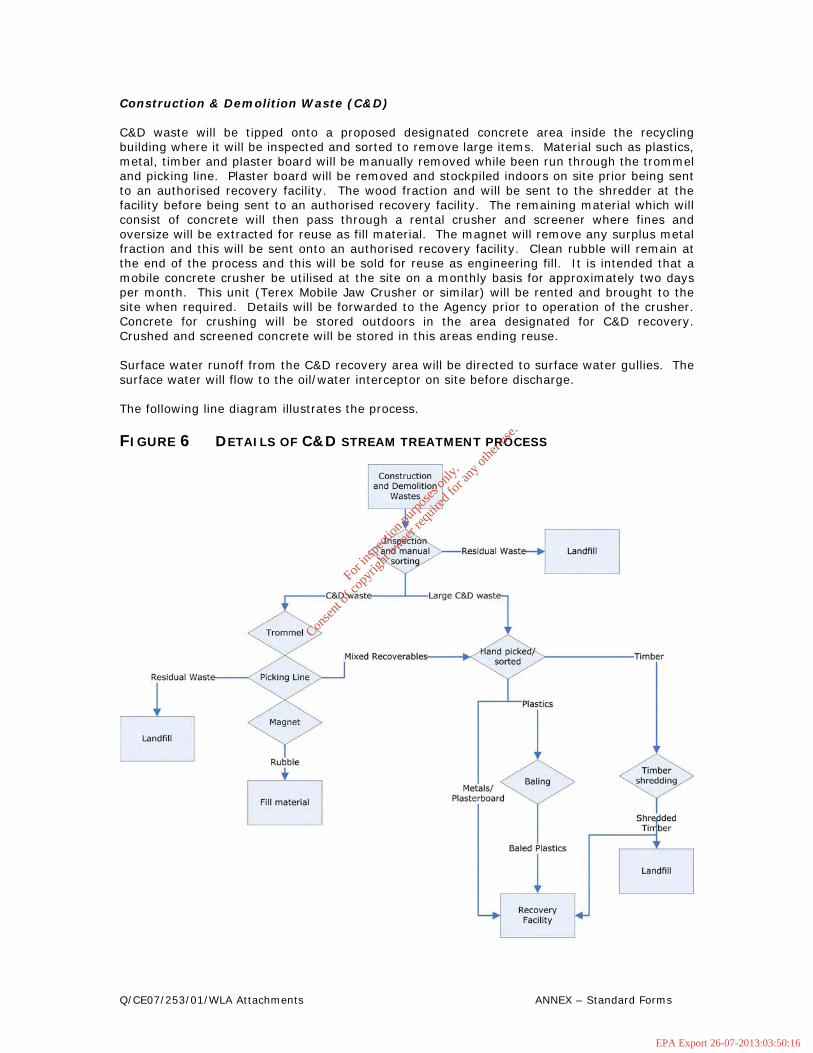
Construction & Demolition Waste (C&D) C&D waste will be tipped onto a proposed designated concrete area inside the recycling building where it will be inspected and sorted to remove large items. Material such as plastics, metal, timber and plaster board will be manually removed while been run through the trommel and picking line. Plaster board will be removed and stockpiled indoors on site prior being sent to an authorised recovery facility. The wood fraction and will be sent to the shredder at the facility before being sent to an authorised recovery facility. The remaining material which will consist of concrete will then pass through a rental crusher and screener where fines and oversize will be extracted for reuse as fill material. The magnet will remove any surplus metal fraction and this will be sent onto an authorised recovery facility. Clean rubble will remain at the end of the process and this will be sold for reuse as engineering fill. It is intended that a mobile concrete crusher be utilised at the site on a monthly basis for approximately two days per month. This unit (Terex Mobile Jaw Crusher or similar) will be rented and brought to the site when required. Details will be forwarded to the Agency prior to operation of the crusher. Concrete for crushing will be stored outdoors in the area designated for C&D recovery. Crushed and screened concrete will be stored in this areas ending reuse. Surface water runoff from the C&D recovery area will be directed to surface water gullies. The surface water will flow to the oil/water interceptor on site before discharge. The following line diagram illustrates the process.
FIGURE 6 DETAILS OF C&D STREAM TREATMENT PROCESS
For
insp
ectio
n pur
pose
s only
.
Conse
nt of
copy
right
owne
r req
uired
for a
ny ot
her u
se.
EPA Export 26-07-2013:03:50:16

Q/CE07/253/01/WLA Attachments ANNEX – Standard Forms
D2C EMISSIONS
There is potential for the following emissions;
• Air (dust and odour) • Noise from operational plant traffic and construction plant • Leachate from stored waste • Uncontrolled emission to surface or ground from spillages • Litter from transport of waste
Comprehensive environmental controls and monitoring are presently in operation to mitigate the occurrence of any of the above emissions. The mitigation measures are described in attachment F Control and monitoring. D2d Laboratory There is no laboratory on site; however, Murray Waste Recycling Ltd employs contract laboratories to undertake routine analyses of surface water, groundwater, and air (dust) in compliance with the permit. D2e Incineration
This section is not applicable.
For
insp
ectio
n pur
pose
s only
.
Conse
nt of
copy
right
owne
r req
uired
for a
ny ot
her u
se.
EPA Export 26-07-2013:03:50:16

Q/CE07/253/01/WLA Attachments ANNEX – Standard Forms
ATTACHMENT E EMISSIONS
Emission points are presented in Drawing CE07-253-01_207. E1 Emissions to Atmosphere The main potential environmental emissions to air from the facility are:
• Odour • Dust
The waste recycling building is a fugitive odour emission point. Municipal solid waste will be trommellled upon arrival at the facility. The recoverable fraction will be removed. Residual waste will be placed in an ejector trailer for shipping to landfill. The ejector trailer will be stored indoors. It is envisaged that the ejector trailer with waste will not be stored for period’s greater than 48 hours, thus keeping odour build up to a minimum. The yard is a fugitive dust emission area. Monitoring of total dust deposition will be conducted in accordance with the waste licence. Any noticeable dust emissions at the site will be dealt with immediately by either removing the source of the dust or spraying water. There is also a minor emission from the boiler used to heat the administration offices on site. E2 Emissions to Surface water There are two surface water emission points at the site. There is one emission point for surface water from the oil/water interceptor (SW3). There is another emission point (SW4) which discharges the roof water from the recycling building to the stream running adjacent to the recycling building. The locations of these emission points are shown on Drawing CE07-253-01_207 and detailed in Table E.2 (i). Potential emissions to surface water include:
• Suspended solids • Leachate-related contamination • Fuel and other oils-related contamination
With the exception of roof water, all surface water generated on site is routed through an oil-water interceptor prior to discharge. The leachate drainage system in the shed will be completely isolated from the surface water drainage network and will be routed to a leachate collection tank, pending collection to an off site approved WWTP. All roads and parking areas flow to the interceptor thus any spillages are held back from the stream. The on-site diesel tanks are fully bunded.
For
insp
ectio
n pur
pose
s only
.
Conse
nt of
copy
right
owne
r req
uired
for a
ny ot
her u
se.
EPA Export 26-07-2013:03:50:16
Q/CE07/253/01/WLA Attachments ANNEX – Standard Forms
E3 Emissions to sewer There is no mains sewer connection therefore no discharge to sewer. E4 Emissions to Groundwater There is one emission to groundwater at the site (GWE1) as shown in Drawing CE07-253-01_207. This is a raised percolation area from the on site WWTP. This WWTP deals only with the wastewater from the administration building toilets, and canteen. The location of the WWTP and associated infrastructure is shown in Drawing CE07-253-01_206. The specification of the treatment system is shown in Attachment D1. E5 Noise emissions
• Noise o On-site machinery (Timber shredder, Baler, Trommel and Picking Line, C&D
recovery plant) o Delivery vehicles o Construction plant
There are two potential noise emission points. These are N1 and N2 as shown in Drawing CE07-253-01-207 and refer to the concrete crusher/screener and the wood shredder respectively. The concrete crusher/screener will be used on an intermittent basis (approximately 2 days per month) and the wood shredder approximately two days per week depending on quantities accepted on site. The equipment will be maintained to manufactures standards and the plant will not be operated at unreasonable hours. This standard extends to hired-in plant; any unduly noisy plant is prohibited from site. Noise from delivery vehicles is mitigated by speed control and also by the presence and continuing development of screening mounds. Noise monitoring has been conducted at the facility in accordance with the waste permit. These results are summarised in Tables I6 in attachment I. Attachment E6 Environmental Nuisance E.6.1 Bird Control Birds will not pose a significant risk at the facility as the final products are of low nutritional value to macro-organisms. Municipal solid waste material will be processed and stored inside the recycling building. Residual waste will be stored in an ejector trailer in the truck bay inside the building until it is ready for transfer to a licensed landfill or other appropriate licensed facility. E.6.2 Dust Control Internal access road is concrete and all waste activities will be conducted on concrete hardstanding areas. Any dust arising on the access road on site will be suppressed with water and swept with a road sweeper with dust suppression system. Mist air dust suppression systems are utilised within the main recycling building to minimise dust. Any dust arising from the recovery of C&D material at the site will be minimised by the used of dust suppression sprays as deemed necessary. Monitoring of total dust deposition levels will continue.
For
insp
ectio
n pur
pose
s only
.
Conse
nt of
copy
right
owne
r req
uired
for a
ny ot
her u
se.
EPA Export 26-07-2013:03:50:16

Q/CE07/253/01/WLA Attachments ANNEX – Standard Forms
E.6.3 Fire Control Emergency response procedures are in place as part of the Environmental Management Programme. All site operator and staff will be made aware of the dangers of fires and how to treat them. A fire Safety Certificate application is currently with the Wexford County Council fire safety officer. Provision has been made for the supply of a 240m3 fire water supply tank. The location of this tank is shown in drawing CE07-253-01-206. Precautions to be taken in order to ensure fire safety:
• All operatives will receive basic instructions on fire safety and protocol. • A number of operatives are to attend fire officer training courses. At least one of these
fire officers will be on-site at all operational times. • A Fire Safety Drill and a Code of Practice will be developed by the site management.
All staff will be fully trained with this code. • The phone number of the local fire station will be posted in prominent positions
throughout the various buildings on site. E.6.4 Odour control Operations at the facility involve the collection of recyclable material and the compaction and transfer of solid waste. No liquids, agricultural or sewage sludges will be accepted at the site. Waste accepted at the facility will have generally undergone relatively little decomposition and so will have little potential for odour generation. For the fraction of domestic/municipal waste that is deposited on site which does have odour generation potential, odour is actively controlled at the recycling building with odour neutralising spray mist. Waste is stored in the building and is removed from site every two days to minimise potential for odour generation. E.6.5 Litter control Implementation of the following control measures will minimise the potential for litter problems:
• All waste handling and processing (with the exception of C&D recovery) will be carried out in the enclosed facility only.
• All incoming and outgoing vehicles carrying waste will be covered. • A daily litter patrol of the site and nearby roads will be carried out by a site
operator, and a daily inspection sheet completed. • Regular sweeping of the tipping floor and good housekeeping practices will
prevent windblown materials. • Waste will be baled, tied and placed in enclosed articulated lorries or
appropriately covered vehicles before exiting the facility. E.6.6 Traffic The traffic management system will include speed restrictions and warning notices. The traffic will be separated by means of road markings to ensure vehicles stay within their designated movement streams and lanes.
For
insp
ectio
n pur
pose
s only
.
Conse
nt of
copy
right
owne
r req
uired
for a
ny ot
her u
se.
EPA Export 26-07-2013:03:50:16

Q/CE07/253/01/WLA Attachments ANNEX – Standard Forms
The following additional measures will be used to control the traffic into and out of the site.
• The weighbridge operator will monitor the access and egress of vehicles. • There are adequate parking spaces on the site of the facility. • The traffic control point is set back from the main entrance which will prevent
the queuing of vehicles on the entrance road. • A clean and well serviced fleet will be maintained at all times.
E.6.7 Vermin control Vermin will not pose a significant risk at the facility as the materials are of low nutritional value to macro-organisms. A pest control management system will be implemented. Murray Waste Recycling Ltd. currently employs a subcontractor (Rentokil) to be responsible for pest control on the site. They visit the site on a monthly basis. Insecticide will be used if necessary to control fly infestations that may occur. Residual waste is removed from site within 48 hours to prevent the attraction of vermin to the site. Emission points are presented in drawing CE07-253-01-207.
For
insp
ectio
n pur
pose
s only
.
Conse
nt of
copy
right
owne
r req
uired
for a
ny ot
her u
se.
EPA Export 26-07-2013:03:50:16

For
insp
ectio
n pur
pose
s only
.
Conse
nt of
copy
right
owne
r req
uired
for a
ny ot
her u
se.
EPA Export 26-07-2013:03:50:16