The DeepRoot Silva Cell Integrating Trees, Soil & Stormwater for Sustainable Development.

1
Attachment 1
Manufactured Treatment Device (MTD) Registration 1. Manufactured Treatment Device Name:
Silva Cell Suspended Pavement System with Bioretention 2. Company Name:
DeepRoot Green Infrastructure 101 Montgomery Street, Suite 2850 San Francisco, CA 94104
Company Profile:
DeepRoot Green Infrastructure develops solutions to enhance urban forests and surrounding watersheds in city streets, parking lots, campuses and heavily paved areas. Silva Cell, our flagship product, is an underground framework for containing lightly compacted soil that supports large trees and absorbs stormwater runoff, improving air and water quality, reducing energy demand, mitigating head island effect and nurturing trees for a long life in their communities. Headquartered in San Francisco with location in Vancouver and London, DeepRoot has more than forty years of experience helping trees thrive in cities, nurturing over 500 blocks of urban treescape in the built environment around the world.
DeepRoot was founded in 1976 when an industrial designer tripped on an uprooted sidewalk and ruined a new pair of shoes. This eventually led him to develop the first commercially available tree root barriers. From that simple start, we are now a leading urban landscape products and ecosystem services supplier, focused primarily on integrating trees, soil, and stormwater into the urban environment. Our products include Silva Cell, Root Barrier, Geomembranes (Water Barrier/Bamboo Barrier), and ArborTie staking and guying material. Our vision is to create thriving, resilient urban ecosystems comprised of mature, vigorous trees and healthy watersheds. We are committed to enhancing the built environment with innovative and quality products and services that create green infrastructure. We believe this is essential to the creation of healthy and thriving urban spaces.
2
3. Contact Name (to whom questions should be addressed):
Brenda Guglielmina DeepRoot Southeast Account Manager
46 Sunrise Drive Asheville, North Carolina 28806 (t) 404.378.9390 (m) 404.358.6306 [email protected] www.deeproot.com
4. Technology
Activities associated with urbanization compact soils, which greatly reduces tree canopy height and width, root growth, and life span (Yung, 1993). Structural soils were proposed to offset the effects of compacted urban soils by distributing the surface load over a coarse aggregate base with tree planting soil mixed into the aggregate void space (Smiley et al., 2006). However, laboratory and field evaluations have shown that most street trees still do not reach maturity when planted in structural soils because there is not enough soil available within the aggregate to sustain growth (Smiley et al., 2006). To improve upon the principles of structural soils, DeepRoot Green Infrastructure developed a product called the “Silva Cell™”. The Silva Cell™ creates a suspended pavement system, which transfers the static and active loads above the Silva Cells to a compacted aggregate sub-grade. Silva Cells are a plastic composite grid structures with 92% void space that support load up to AASHTO H-20 standards (Figure 4-1). Stormwater runoff can be routed through the Silva Cell’s soil and tree root matrix, thus creating a vegetated subsurface bioretention treatment system. The design and sizing process of the Silva Cell Suspended Pavement System with Bioretention can remain the same as the guidance described in VA DCR Stormwater Design Specification No. 9 (VA DEQ, 2013). Stormwater runoff may be stored above the filter media contained within the Silva Cell™ unit and within the aggregate layer above the decks similar to “bowl” storage in standard bioretention.
DeepRoot manufactures the Silva Cell product, including the recently released Silva Cell 2, designed to be more efficient to manufacture, ship and install (Figure 4-2). DeepRoot and select contractors provide technical support, installation guidance and design review on an as needed basis to engineers and landscape architects using the product for stormwater management and urban forestry.

3
Figure 4-1: Silva Cell conceptual rendering (left) and components (right)
Figure 4-2: Silva Cell 2 Product from DeepRoot Green Infrastructure
Simply described, the Silva Cell allows a bioretention system to be used underground and beneath pavements. Bioretention systems maintain or restore pre-development hydrology by providing depressional storage and infiltration, which enhances ground water recharge and natural base flow to streams (Davis et al., 2009; DeBusk et al., 2011). Hydrologically, these systems tend to perform better under warm and dry conditions (i.e., low antecedent moisture conditions and high potential evapotranspiration) (Hunt et al., 2006; Davis, 2008; Li et al. 2009). The ability of a bioretention system to mitigate peak discharge is directly linked to the infiltration rate and water-free pore space of the fill media, and bioretention systems have been shown to reduce peak discharges by up to 96% for events that do not overtop the bowl (Dietz and Clausen, 2005; Hunt et al., 2008). In several studies bioretention systems eliminated runoff

4
entirely from storms less than the water quality volume (Dietz and Clausen, 2005; Hunt et al, 2006; Davis, 2008; Brown and Hunt, 2011). bioretention systems with greater volumes of fill media are better suited to capture runoff volumes from larger rainfall events (Li et al., 2009).
Water quality evaluations have shown particulate pollutants are effectively removed by the soil media. The water quality benefits of a bioretention systems are driven by hydrology as dramatic reductions in mass export are observed frequently with less substantial concentration reductions reported (Li and Davis, 2009; Brown and Hunt, 2011). Heavy metals and total suspended solids (TSS) have consistently been retained well by bioretention systems through filtration, sedimentation and adsorption; mass load reductions of TSS, copper (Cu), lead (Pb) and zinc (Zn) are usually greater than 85% (Hunt et al., 2008; Li and Davis, 2009; Brown and Hunt, 2011). Hunt et al. (2006) found that phosphorus (P) retention in BRSs is highly dependent upon the P-index (P content) of the fill media and TSS retention. Particle bound P (PBP) is captured without difficulty at the soil media surface, but a low P-index in necessary to ensure (dissolved) orthophosphate (O-PO4
3-) is not exported (Hunt et al., 2006; Hatt et al., 2009). Retention of O-PO4
3- is important in nutrient sensitive freshwater ecosystems because excess P can cause algal blooms and lead to eutrophication in lakes (Schindler, 1975). In some instances, particle bound P separated from Fe or Al oxides in bioretention systems soil media under reduced redox potentials (Dietz and Clausen, 2006; Hunt et al., 2006).
Nitrogen (N) retention within bioretention systems is influenced by particulate capture, vegetation uptake and biological transformations. Organic nitrogen (ON) and total ammoniacal nitrogen (TAN) (thus, TKN) are typically retained well by BRSs, but nitrate-nitrogen (NO2,3-N) is retained poorly (Davis et al., 2003, Dietz and Clausen, 2005; Dietz, 2007; Hunt et al., 2008; Brown and Hunt, 2011). Unless specifically designed otherwise, BRSs are predominantly aerobic systems and transformations of ON and TAN to NO2,3-N occur readily through mineralization, ammonification and nitrification during inter-event dry periods (Kim et al., 2003; Lucas and Greenway, 2011; Hunt et al., 2012). NO2,3-N stored in the soil media is then flushed from the system during the next precipitation event, resulting in higher effluent concentrations of NO2,3-N than were observed in untreated influent runoff (Kim et al., 2003; Davis et al. 2001, 2006; Hunt et al. 2006, 2008; Hatt et al. 2009). Hunt (2003) and Kim et al. (2003) proposed the internal water storage zone (IWS) to increase NO2,3-N retention by maintaining a saturated layer of soil within BRSs, and several studies have shown improved NO2,3-N retention with the simple design modification (Passeport et al., 2009; Brown and Hunt, 2011; Luell et al., 2011; Lucas and Greenway, 2011). IWS also substantially improves runoff volume reduction when underlying soils are sandy (Passeport et al., 2009; Brown and Hunt, 2011).
Street surfaces are sources of stormwater runoff volume and pollutants as well as pathways for the transport of runoff from adjoining land areas (Bannerman et al., 1993). Most municipal streets and roadways are directly connected to conventional storm sewer networks with curb and gutter drainage systems. The subsurface channelization of runoff in urban watersheds has been shown to increase peak discharges and reduce lag times (Leopold, 1968). Directly connected impervious areas (DCIA) rapidly convey runoff to the watershed outlet and are the primary contributor of storm flow during small rainfall events (<1 in) (Walsh, 2000; Walsh, 2004; Flint and Davis, 2007). Walsh (2004) suggested DCIA is a more appropriate predictor of stormwater impacts to surface waters than total impervious area (TIA) of a watershed, and DCIA is particularly important in watersheds with sandy soils (Lee and Heaney, 2001).
5
Utilizing the proven treatment processes of bioretention with the Silva Cell™ suspended pavement system, some of the hydrologic and water quality impacts of DCIA in ultra-urban environments can be mitigated by creating subsurface storage and treatment of runoff beneath paved surfaces. Specific size/capacity of MTD assessed (include units): Table 8-1 outlines the site specific components of the field performance evaluation. Range of drainage areas served by MTD (acres): The Silva Cell Suspended Pavement System with Bioretention has been used to capture and treat runoff from urban drainage areas ranging in size from 0.01 ac to 0.5 ac. The two contributing drainage areas included in the field performance evaluation were 0.10 ac and 0.12 ac.
Include sizing chart or describe sizing criteria: The Silva Cell units are manufactured in standard sizes as described by Figure 4-2. Sizing of the system and the number of Silva Cell units needed is dependent upon the volume of runoff the designer must capture and treat. For a system that incorporates 6” of volume storage above the filter media, one (1) Silva Cell Unit would be needed for every 4 ft3 of runoff. Similarly, for a system with 12” of volume storage above the filter media, one (1) Silva Cell Unit would be needed for every 8 ft3 of runoff. Intended application: on-line or offline: The Silva Cell Suspended Pavement System with Bioretention is typically an offline application. Runoff may be conveyed to the bioretention zone of the system in a variety of ways that may include, but is not limited to: a new catch basin with distribution pipe, a tree well with high flow material at the opening and a vertical stand or overflow pipe or via flow through permeable pavement and the associate aggregate layer. Other configurations may be considered. One of the strengths of the Silva Cell Suspended Pavement System with Bioretention is it’s flexibility in configuration for each individual project. Media used (if applicable): The filter media used in the field performance test followed the recommended VA DEQ bioretention filter media. Table 8-1 outlines the filter media used for the performance test. Recommended filter media is described below per VA DEQ.
Additional information on the field performance evaluation and the filter media used is included in Section 8.

6
5. Warranty Information (describe, or provide web address):
Official warranty information on company letterhead has been attached to this application. 6. Treatment Type
Hydrodynamic Structure Filtering Structure Manufactured Bioretention System Provide Infiltration Rate (in/hr):
Other (describe):
As described above, the Silva Cell™ Suspended Pavement System with Bioretention allows a typical bioretention system (Level 1 or Level II as described by VA DEQ) to be used below grade and contained within the modular structure of the Silva Cell™ unit. The design and sizing process may remain the same as the guidance described in VA DCR Stormwater Design Specification No. 9 (VA DEQ, 2013) for permitting and approval. The treatment process and pollutant removal mechanisms remain the same as a standard bioretention system.
7. Water Quality Treatment Mechanisms (check all that apply)
Sedimentation/settling Infiltration Filtration (specify filter media)
The filter media used in the field performance test followed the recommended VA DEQ bioretention filter media. Table 8-1 outlines the filter media used for the performance test. Recommended filter media is described below per VA DEQ.
From VA DCR Stormwater Design Specification No. 9 (VA DEQ, 2013) recommended VA
DEQ bioretention media:
General Filter Media Physical Composition. The mineral soil texture of the bioretention
soil mix should be loamy coarse sand with no more than 10% clay and at least 10% but no more than 20% silt + clay; at least 75% of the sand fraction should be coarse or very coarse sand.
To allow for appropriate Cation Exchange Capacity (CEC) and nutrient removal, the mix
should contain at least 10% soil fines (silt + clay) while meeting the overall texture specification above. The particle size analysis must be conducted on the mineral fraction only or after following appropriate treatments to remove organic matter before the particle size analysis.
The Filter Media should contain 3% to 5% organic matter, as determined by the conventional Walkley-Black soil organic matter determination method or a similar analysis. Soil organic matter is expressed on a dry weight basis and does not include coarse particulate (visible) components.
7
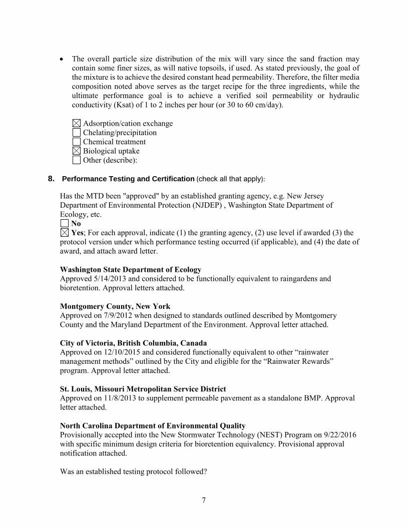
The overall particle size distribution of the mix will vary since the sand fraction may
contain some finer sizes, as will native topsoils, if used. As stated previously, the goal of the mixture is to achieve the desired constant head permeability. Therefore, the filter media composition noted above serves as the target recipe for the three ingredients, while the ultimate performance goal is to achieve a verified soil permeability or hydraulic conductivity (Ksat) of 1 to 2 inches per hour (or 30 to 60 cm/day).
Adsorption/cation exchange Chelating/precipitation Chemical treatment Biological uptake Other (describe):
8. Performance Testing and Certification (check all that apply):
Has the MTD been "approved" by an established granting agency, e.g. New Jersey Department of Environmental Protection (NJDEP) , Washington State Department of Ecology, etc.
No Yes; For each approval, indicate (1) the granting agency, (2) use level if awarded (3) the
protocol version under which performance testing occurred (if applicable), and (4) the date of award, and attach award letter. Washington State Department of Ecology Approved 5/14/2013 and considered to be functionally equivalent to raingardens and bioretention. Approval letters attached. Montgomery County, New York Approved on 7/9/2012 when designed to standards outlined described by Montgomery County and the Maryland Department of the Environment. Approval letter attached. City of Victoria, British Columbia, Canada Approved on 12/10/2015 and considered functionally equivalent to other “rainwater management methods” outlined by the City and eligible for the “Rainwater Rewards” program. Approval letter attached. St. Louis, Missouri Metropolitan Service District Approved on 11/8/2013 to supplement permeable pavement as a standalone BMP. Approval letter attached. North Carolina Department of Environmental Quality Provisionally accepted into the New Stormwater Technology (NEST) Program on 9/22/2016 with specific minimum design criteria for bioretention equivalency. Provisional approval notification attached. Was an established testing protocol followed?

8
No Yes, (1) Provide name of testing protocol followed, (2) list any protocol deviations:
Was an established testing protocol followed? The TARP Protocol for Stormwater BMP Demonstrations was followed for the field performance study. Provide the information below and provide a performance report (attach report):
For field tests:
i. Provide the address, average annual rainfall and characterized rainfall pattern,
and the average annual number of storms for the field-test location:
See Table 8-1 and Section 8 below.
ii. Provide the total contributing drainage area for the test site, percent of impervious area in the drainage area, and percentages of land uses within the drainage area (acres):
See Table 8-1 and Section 8 below.
iii. Describe pretreatment, bypass conditions, or other special circumstances at the test site:
At the test sites, a new stormwater catch basin was installed with a 6” pipe to route runoff from the street surface to the interior of the system. A Trashgaurd insert was installed over the inlet of the pipe as pre-treatment to prevent sediment, leaf litter, woody debris and trash from being conveyed to the interior of the system. Bypass did occur during the study as the system is designed to function offline. When bypass occurs, runoff continues flowing down the curb line to the next stormwater catch basin. Additional detail is included in Table 8-1 and Section 8 below.
iv. Provide the number of storms monitored and describe the monitored storm events
(amount of precipitation, duration, etc.):
The Silva Cell™ retrofits were monitored from June 2012 through July 2013. Over the monitoring period 59 storms above 0.10 in were recorded for a total of 47.6 in, which was 11% below normal (Table 8-2). For water quality, 21 and 19 sets of paired water quality samples were collected from the Ann Street and Orange Street sites, respectively. Additional detail is provided in Table 8-2 and Section 8 below.
v. Describe whether or not monitoring examined seasonal variation in MTD
performance:
Seasonal variations were not considered in this field performance evaluation. However, if seasonal variations in water quality treatment performance exist, they will follow those of bioretention. Some seasonal variations in TN and NO2,3-N removal have been

9
reported in several bioretention studies, where denitrifying bacteria are more active and treatment capacity is higher during spring and summer.
vi. If particle size distribution was determined for monitored runoff and/or sediment
collected by the MTD, provide this information:
PSD data not available for field performance evaluation.
The field scale evaluation of two (2) Silva Cell™ Suspended Pavement Systems with Bioretetion is described below. Additionally, a peer reviewed journal article detailing the study and published in Ecological Engineering is also attached. Plansheets from the project are also attached to this application.
The study site is located in Wilmington, NC. Wilmington is located in the southern coastal plain between the Cape Fear River and the Atlantic Ocean. On average, Wilmington International Airport receives 57 in of rainfall annually. The study site is part of the Burnt Mill Creek watershed of the Cape Fear River Basin. The Burnt Mill Creek watershed is on North Carolina’s 303(d) list, with toxicity and sedimentation cited as the primary causes of impairment (NCDENR, 2004). Two small urban drainage areas in Wilmington, North Carolina were selected for Silva Cell™ retrofits (Figure 13-1). The DCIA (street surface) of the Orange Street and Ann Street retrofit sites was similar at 0.10 ac and 0.12 ac, respectively (Table 2). Average slopes of the contributing drainage areas were similar at 2.5% and 1.8%.
Figure 8-1: Research site contributing drainage areas

10
Table 8-1: Research Site Summary
Parameter Orange Street Ann Street DCIA (ft2) 4,360 (0.10 ac) 5,231 (0.12 ac) % Imperviousness 100% 100% Slope 2.5% 1.8% SCM Location N 34.233660 W 77.936588 N 34.232327 W 77.936459 Receiving Water Body Burnt Mill Creek River Basin Cape Fear
Silva Cell™ Design Summary Silva Cell™ Frames 68 Silva Cell™ Decks (units)
34
Surface Area 297 ft2 Soil Volume 750 ft3 Street Surface Area (DCIA)
4,360 ft2 5,231 ft2
Loading Ratioa 15:1 18:1 Design Storm Depth
Soil Media Compositionb Gravel 4.5% 0.0% Sand 87.4% 87.3% Silt 7.0% 8.7% Clay 1.1% 4.0% Organic Matter 3% 6% aDCIA/SCM surface area bGravel, sand, silt and clay gradations are by volume; organic matter is by weight
Installation of the two Silva Cell™ retrofit sites occurred from mid-June to mid-July 2012. Each Silva Cell™ retrofit was constructed with 68 frames for 34 total units in a two-layer system. Each frame is 48 in long by 24 in wide by 16 in high; with the two-layer system the total media depth is 32 in. The frames were laid out four across with two additional units placed sideways at one end of the excavated area. Above the upper layer of frames, a set of decks was installed to distribute the loading from the sidewalk above.
To begin construction, the retrofit sites were excavated to an average depth of 4.3 ft such that the base was flat (Figure 8-2). A geotextile was then installed over the bottom of the excavated area to prevent ripping of the geomembrane (pond liner, impermeable to water), which was installed above the geotextile. Another geotextile was placed on top of the geomembrane, followed by 4 in of ASTM #57 stone (8-2). This stone layer was compacted with three passes of a plate compactor and screeded until level (flat). The first layer of frames was then installed, spaced approximately 1.75 in apart. Underdrains were installed along the bottom of the frames and covered with a 2 in rock collar (Figure 8-3). The soil media was then installed up to the level of the top of the first set of frames. The second layer of frames was installed, followed by additional soil media, and the 6 in diameter distribution pipes (Figure 8-3). The distribution pipes were encased in a 2 in rock collar and zip tied to the decks. The decks were screwed onto the upper set of frames and the geomembrane was sealed around the whole system (Figure 8-

11
4). Influent runoff could only leave the system through outflow or evapotranspiration (i.e. no exfiltration into the in situ soils). The geomembrane was used for the purposes of the study and is atypical from other Silva Cell™ installations, as it is usually desirable to exfiltrate as much influent runoff as possible from SCMs. The geomembrane was used to isolate the Silva Cell™ systems and to ensure adequate water quality samples were collected. A 4 in layer of ASTM #57 stone was place on top of the sealed system. The excavated area was back filled to the existing grade and the sidewalk was reinstalled (Figure 8-4). Finally, a crape myrtle (Lagerstroemia indica x fauriei) was installed in the remaining tree opening such that its roots could spread out into the uncompacted soil (Figure 8-5, 8-6).
Figure 8-2: Excavation completed with geomembrane and geotextile in place (left); frames placed over sub-grade with underdrains being installed (right)
Figure 8-3: First lift of media placed within frames (left); distribution pipes and rock collar installed over second lift of media (right)

12
Figure 8-4: First lift of media placed within frames (left); distribution pipes and rock collar installed over second lift of media (right)
Figure 8-5: Decks installed (left); site is backfilled and sidewalk is replaced with tree opening intact (right)

13
Figure 8-6: Completed Silva Cell™ retrofit at Orange Street with tree installed
Runoff was routed through the Silva Cell™ retrofits by installing a new catch basin at the edge-of-curb on the upslope end of each system (Figure 9). A single 6 in diameter PVC pipe (with a debris rack to prevent clogging) was installed from the catch basin to provide conveyance. Upon entering the Silva Cells™, the single inlet pipe was split to two perforated 6 in diameter PVC pipes, located at the top of the cross section. Influent runoff then passed vertically through the uncompacted soil media, which acted as a filter. Three 4 in perforated PVC underdrains were used to drain the system between storm events. The underdrains were fitted with a 90 degree upturned elbow to create an IWS zone with 16 in of ponding, and tied into the storm sewer network via existing catch basins down slope of the retrofits. This configuration also allowed for storm flows above the design flowrate to be bypassed along the existing curb line. The Silva Cell™ retrofits were monitored from June 2012 through July 2013. Over the monitoring period 59 storms above 0.10 in were recorded for a total of 47.6 in, which was 11% below normal (Table 8-2). For water quality, 21 and 19 sets of paired water quality samples were collected from the Ann Street and Orange Street sites, respectively. At the Ann Street inlet, 32.7 in of runoff was observed and 23.5 in (68%) was treated by the Silva Cell™ retrofit (Figure 15). Thus, 32% of the cumulative runoff observed at the inlet bypassed the system and 40% (21 of 53) of the rainfall events generated bypass. Bypass typically occurred when 5-minute peak rainfall intensities were greater than 2 in/hour. There are two factors that likely contributed to runoff bypassing the system: (1) trash, leaf litter, and woody debris that restricted flow from the new catch basins to the distribution pipes (Figure 16) and (2) high

14
hydrologic loading ratios that lead to greater flow rates than the soil media in the Silva Cell™ retrofits was able to hydraulically convey. Table 8-2: Precipitation summary
N Range Mean Median Total
59 0.10 – 2.82 0.79 0.60 46.7 From June 2012 to July 2013, 21 and 19 sets of paired water quality samples were collected from the Ann Street and Orange Street sites, respectively. Event mean concentrations (EMCs) and percent removals on a concentration basis at both sites are included in Table 8-3. In general, influent pollutant concentrations at Orange Street were greater than those observed at Ann Street, and all pollutants sampled at both sites significantly decreased from inlet to outlet. TKN concentrations at the Ann Street and Orange Street sites decreased significantly by 71% and 84%. Respectively. Mean effluent TKN concentrations at Ann Street were 0.22 mg/L and 0.33 mg/L at Orange Street, which are very similar to effluent concentrations reported in the most recent bioretention system study in North Carolina (Luell et al., 2011). The decrease in TKN concentrations is primarily due to particulate ON retention, though TAN concentrations decreased significantly at both sites.
Table 8-3: EMCs, percent removals and statistical findings for 2012 – 2013 study
Pollutant Ann Street Orange Street Effluent
Comparison n IN OUT Change (%) n IN OUT Change (%)
TKN 21 0.75 0.22 -71%T* 18 1.99 0.33 -84% T* p=0.0056* NO2,3-N 21 0.08 0.05 -35%T* 18 0.17 0.07 -60% T* p=0.3322 TAN 21 0.11 0.03 -73% T* 18 0.33 0.08 -76% T* p=0.0082* TN 21 0.82 0.27 -66% T* 18 2.17 0.40 -82% T* p=0.0158* ON 21 0.64 0.19 -70%T* 18 1.67 0.25 -85%T* p=0.0287* O-PO43- 20 0.03 0.01 -70% T* 19 0.18 0.03 -82% T* p<0.0001* TP 21 0.12 0.03 -72% T* 18 0.41 0.11 -74% T* p=0.0002* PBP 20 0.09 0.02 -73% T* 18 0.23 0.08 -67% T* p<0.0001* TSS 21 45 6 -86% S* 19 101 8 -92% T* p=0.4292 Cua 21 14.3 2.1 -85% T* 19 10 1.4 -86% T* p=0.1590 Pba 21 9.8 1.0 -90% S* 19 16 1.0 -94% T* NA Zna 21 64 11 -83% T* 19 82 11 -76% T* p=0.9760 *Significantly different (α=0.05) aHeavy metals concentrations in units of μg/L bAll effluent Pb concentrations were below PQL, statistical analysis not available SSign test used for statistical comparison TPaired t test used for statistical comparison “-“ negative sign inmdicates a decrease in pollutant concentration
At the Orange Street site, NO2,3-N concentrations significantly decreased by 60% from 0.17 mg/L to 0.07 mg/L. A lesser, but still significant, 35% decrease in NO2,3-N concentration occurred at Ann Street from 0.08 to 0.05 mg/L, which is likely due to lower influent NO2,3-N concentrations. There was no statistical difference in effluent NO2,3-N concentrations despite varying the organic

15
matter content at the Ann Street and Orange Street sites at 6% and 3%, respectively. Effluent NO2,3-N concentrations were very low compared to other studies of BRSs in the peer-reviewed literature (Davis et al., 2006; Hunt et al., 2008; Brown and Hunt, 2011). NO2,3-N is dissolved and retained poorly by sandy characteristic of filter media. Inclusion of the IWS layer and impermeable geomembrane likely enhanced conversion of NO2,3-N to N2 through denitrification. Runoff remained ponded in the IWS layer during inter-event dry periods under anoxic conditions and was flushed from the system during the following precipitation event leading to lower effluent NO2,3-N concentrations. TP concentrations significantly decreased 72% at Ann Street and 74% at Orange Street. Mean effluent TP concentrations at Ann Street were 0.03 mg/L and 0.11 mg/L at Orange Street. At Ann Street, mean influent concentrations were relatively low at 0.12 mg/L and below a previously suggested irreducible concentration to TP, however a significant decrease in effluent TP concentration was still observed (Strecker et al., 2001). In bioretention systems, TP removal is linked to TSS retention (as shown by the decrease in PBP concentration), which was 86% and 92% and the Ann Street and Orange Street retrofits, respectively (Hunt et al., 2012). Effluent TSS concentrations were not significantly different. Removal of dissolved O-PO4 was excellent (70-82%); effluent concentrations were below 0.03 mg/L at both sites. O-PO4 was likely captured in the upper portions of the soil media because it was not flushed from the system under reduced redox conditions created by the anoxic IWS layer (Dietz and Clausen, 2006; Hunt et al., 2012). When the soil media was placed in the Silva Cell™ retrofits, the P-index was 5 and the organic matter source was shredded pine mulch bark.
9. MTD History:
How long has this specific model/design been on the market?
The first commercial installation of the Silva Cell product occurred in Kelowna, BC (Canada) in 2007. The product began to be installed at projects through the United States and United Kingdom (in addition to Canada) at that point. We completed hundreds of projects in the following six or seven year, at which point we turned our attention to designing a new version of the product.
We knew from customer feedback and field experience that there were specific areas of improvement that we wanted to focus on, including reducing the overall amount of material used, creating a more flexible assembly to accommodate different field conditions, and eliminating the steel tubes in the decks. In 2015, we introduced Silva Cell 2 – a less expensive and more versatile version of the original product.
To date, we have completed over 1,000 Silva Cell projects worldwide.

16
List no more than three locations where the assessed model size(s) has/have been installed in Virginia. If applicable, provide permitting authority. If known, provide latitude & longitude:
Project Location Coordinates Units Surface Area
1 Court Square Harrisonburg, VA 38°27'02.3"N 78°52'06.1"W 50 240 ft2
Downtown Leesburg Leesburg, VA 39°06'49.7"N
77°33'55.4"W 40 160 ft2
Met Park 4/5 Arlington, VA 38°51'47.9"N 77°03'15.3"W 180 480 ft2
List no more than three locations where the assessed model size(s) has/have been installed outside of Virginia. If applicable, provide permitting authority. If known, provide latitude & longitude:
Project Location Address Units Surface Area
University of Maryland, Performing Arts Center
Baltimore, MD 39°15'14.0"N 76°42'51.5"W 90 720 ft2
Martin Luther King Memorial Washington, DC 38°53'19.6"N
77°02'37.5"W 1,250 5,040 ft2
*UNC – “The Pit” Chapel Hill, NC 35°54'37.3"N
79°02'54.8"W 330 2,640 ft2
*Engineering Report attached to this application
A complete list of Silva Cell projects used for stormwater control and treatment in MD, VA, NC and Washington D.C. is also included as an attachment to this application.
10. Maintenance:
What is the generic inspection and maintenance plan/procedure? (attach necessary documents):
The official Operations and Maintenance Manual has been attached to this application for VA DEQ review. General maintenance for a Silva Cell Suspended Pavement System with Bioretention are outlined below:
Clean and / or clear sediment, leaf litter, woody debris and trash from pretreatment features
that may include Trash Guards®, catch basin inserts, screens or grates. Clean and / or clear other pipe inlets, tree openings or other drainage components.

17
Inspect cleanout access to distribution pipes and underdrains if they were included in the design
Inspect monitoring wells and ports for drainage rates and soil saturation if they were included in the design
Inspect and assess the overall health of the trees planted in the filter media, if necessary measure tree DBH, canopy height and width and assess overall vigor.
Is there a maintenance track record/history that can be documented?
No, no track record. Yes, track record exists; (provide maintenance track record, location, and sizing of three to
five MTDs installed in Virginia [preferred] or elsewhere):
Recognizing that maintenance is an integral function of the MTD, provide the following: amount of runoff treated, the water quality of the runoff, and what is the expected maintenance frequency for this MTD in Virginia, per year?
A full site inspection should occur once a year and a qualified profession should certify a the report that is submitted to the permitting municipality. However, it is recommended that pre-treatment components be inspected and debris removed quarterly. Additional detailed information is included in the Operations and Maintenance Manual attached to this application.
Total life expectancy of MTD when properly operated in Virginia and, if relevant, life expectancy of media:
The Silva Cell Suspended Pavement System with Bioretention will use the filter media recommended by VA DCR Stormwater Design Specification No. 9 (VA DEQ, 2013) when installed in Virginia. Life expectancy of the filter media is expected to follow that of the standard bioretention practice used in Virginia. It should be noted that the filter media life expectancy is highly dependent upon pollutant concentrations and annual volume of influent runoff, which will vary from project to project. If VA DEQ has specific concentrations, loads and runoff volumes that must be considered, this can be modeled and produced. Additional detailed information is included in the Operations and Maintenance Manual and Product Warranty attached to this application.
For media or amendments functioning based on cation exchange or adsorption, how long will the media last before breakthrough (indicator capacity is nearly reached) occurs?
The Silva Cell Suspended Pavement System with Bioretention will use the filter media recommended by VA DCR Stormwater Design Specification No. 9 (VA DEQ, 2013). The behavior and characteristics of the filter media used within the Silva Cell Suspended Pavement System are expected to follow that of bioretention in Virginia.
For media or amendments functioning based on cation exchange or adsorption, how has the longevity of the media or amendments been quantified prior to breakthrough (attach necessary performance data or documents)?

18
For media or amendments functioning based on cation exchange or adsorption, how
has the longevity of the media or amendments been quantified prior to breakthrough
(attach necessary performance data or documents)?
The Silva Cell Suspended Pavement System with Bioretention will use the filter media recommended by VA DCR Stormwater Design Specification No. 9 (VA DEQ, 2013). The behavior and characteristics of the filter media used within the Silva Cell Suspended Pavement System are expected to follow that of bioretention in Virginia.
Is the maintenance procedure and/or are materials/components proprietary?
Yes, proprietary No, not proprietary
Maintenance complexity (check all that apply):
Confined space training required for maintenance Liquid pumping and transportation
Specify method: Solids removal and disposal
Specify method: Vac Truck may be used to remove sediment, leaf litter, woody debris and trash. Hand tools may be used to clear other pipe inlets, tree openings, and grates.
Other noteworthy maintenance parameter (describe):
None. 11. Comments
Include any additional explanations or comments:
None.
12. Certification
Signed by the company president or responsible officer of the organization:
“I certify that all information submitted is to the best of my knowledge and belief true, accurate, and complete.”
Signature: __________________________________________________
Name: Graham Ray
Title: CEO
Date: ______________________________________________________
Graham Ray
November 16, 2016