ATS7300 GSM Module - De Beveiligingswinkel · Disable PIN code request on your SIM card ... The GSM...
20
© 2003 GE Interlogix B.V. 1047430 All Rights Reserved 12/2003 1 2 3 4 5 6 7 8 9 10 NC OC Gouvars, Frederique (IndSys, GE Interlogix) GSM Module WHAT DOES IT DO? The ATS7300 enables alarm reporting via GSM. All reporting formats available through PSTN are fully functional, including voice reporting or audio listen-in.The GSM module can be used for primary reporting as well as back-up reporting (using multiple central stations). The ATS7300 has a provision to establish a reliable connection for remote up-/downloading to and from the ATS panel. In data mode the GSM module even can establish a connection up to 4800 baud (for more details and programming options see ATS2000 / 3000 / 4000 Programming manual). A general fault indicator is available (OC) to indicate if the battery is present, the battery fuse is ok and the GSM network is detected. IMPORTANT: Disable PIN code request on your SIM card (via any mobile telephone) For proper operation a GSM card with subscription is mandatory (NOT pre-paid). The ATS7300 will only operate (dial/answer) when connected to the home network. A GSM module during operation can require a maximum of 2A peak current; the back-up battery normally wired to the control panel is now also wired to the GSM module. The GSM module checks the battery operation and disconnects the battery when the battery voltage drops below 9 volts to preserve the battery (deep discharge protection) Make sure the antenna itself is placed outside the control panel. To do up/download via the GSM module, use a SIM card that has fax and data enabled. MOUNTING LOCATION The ATS7300 must be mounted inside an ATS panel housing. Important: 1. Disconnect the mains power before opening the cabinet. Disconnect AC mains plug from AC mains wall socket. OR Disconnect the mains with a dedicated circuit breaker. 2. Disconnect the battery (when applicable). MOUNTING THE UNIT Mounting the ATS7300 into the control panel (ATS4000, Ref. to figure ). 1. Remove the screws and lift off the control panel PCB. 2. Place the extension pillars with the plastic rings on top of the existing pillars . 3. Place the clips in the square holes . 4. Mount the ATS7300 using the screws and extension pillars . 5. Place the ATS control panel PCB back into its original position. Mounting the ATS7300 into the control panel (ATS2000/3000/4500, Ref. to figure ) 1. Place the clips in the square holes (use metal pillars when available). 2. Mount the ATS7300 using screws. Connecting the GSM module Disconnect AC mains plug from AC mains wall socket 1. Remove the battery wires that run from the battery to the control panel. 2. Add the blue “tap connectors” to the red and blue (or black) battery leads. 3. Connect the additional wires, which will be clamped to the GSM module. 4. Before clamping ensure that the battery leads will reach the GMS module as well as the battery. 5. Connect the red wire to BATT IN + and the battery. 6. Connect the blue (or black) wire to BATT IN – and the battery. ATS7300 GSM Module
Transcript of ATS7300 GSM Module - De Beveiligingswinkel · Disable PIN code request on your SIM card ... The GSM...

© 2003 GE Interlogix B.V. 1047430 All Rights Reserved 12/2003
12
34
56
789
10
NCOC
Gouvars, Frederique (IndSys, GE Interlogix)
GSM Module WHAT DOES IT DO? The ATS7300 enables alarm reporting via GSM. All reporting formats available through PSTN are fully functional, including voice reporting or audio listen-in.The GSM module can be used for primary reporting as well as back-up reporting (using multiple central stations).
The ATS7300 has a provision to establish a reliable connection for remote up-/downloading to and from the ATS panel. In data mode the GSM module even can establish a connection up to 4800 baud (for more details and programming options see ATS2000 / 3000 / 4000 Programming manual). A general fault indicator is available (OC) to indicate if the battery is present, the battery fuse is ok and the GSM network is detected.
IMPORTANT:
Disable PIN code request on your SIM card (via any mobile telephone)
For proper operation a GSM card with subscription is mandatory (NOT pre-paid).
The ATS7300 will only operate (dial/answer) when connected to the home network.
A GSM module during operation can require a maximum of 2A peak current; the back-up battery normally wired to the control panel is now also wired to the GSM module. The GSM module checks the battery operation and disconnects the battery when the battery voltage drops below 9 volts to preserve the battery (deep discharge protection)
Make sure the antenna itself is placed outside the control panel.
To do up/download via the GSM module, use a SIM card that has fax and data enabled.
MOUNTING LOCATION The ATS7300 must be mounted inside an ATS panel housing.
Important:
1. Disconnect the mains power before opening the cabinet.
Disconnect AC mains plug from AC mains wall socket. OR Disconnect the mains with a dedicated circuit breaker.
2. Disconnect the battery (when applicable).
MOUNTING THE UNIT Mounting the ATS7300 into the control panel (ATS4000, Ref. to figure ).
1. Remove the screws and lift off the control panel PCB. 2. Place the extension pillars with the plastic rings on top of the
existing pillars . 3. Place the clips in the square holes . 4. Mount the ATS7300 using the screws and extension pillars . 5. Place the ATS control panel PCB back into its original position.
Mounting the ATS7300 into the control panel (ATS2000/3000/4500, Ref. to figure )
1. Place the clips in the square holes (use metal pillars when available).
2. Mount the ATS7300 using screws. Connecting the GSM module
Disconnect AC mains plug from AC mains wall socket
1. Remove the battery wires that run from the battery to the control panel.
2. Add the blue “tap connectors” to the red and blue (or black) battery leads.
3. Connect the additional wires, which will be clamped to the GSM module.
4. Before clamping ensure that the battery leads will reach the GMS module as well as the battery.
5. Connect the red wire to BATT IN + and the battery. 6. Connect the blue (or black) wire to BATT IN – and the battery.
ATS7300GSM Module
2
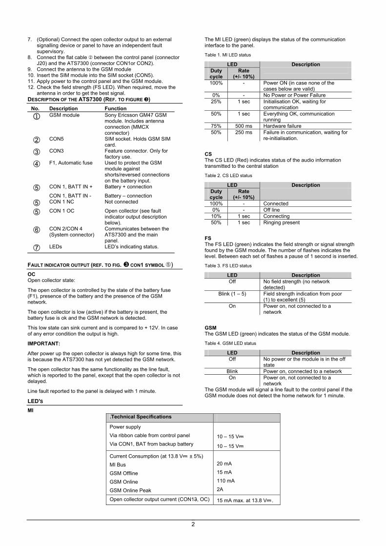
7. (Optional) Connect the open collector output to an external signalling device or panel to have an independent fault supervisory.
8. Connect the flat cable between the control panel (connector J20) and the ATS7300 (connector CON1or CON2).
9. Connect the antenna to the GSM module 10. Insert the SIM module into the SIM socket (CON5). 11. Apply power to the control panel and the GSM module. 12. Check the field strength (FS LED). When required, move the
antenna in order to get the best signal. DESCRIPTION OF THE ATS7300 (REF. TO FIGURE )
No. Description Function
1 GSM module Sony Ericsson GM47 GSM module. Includes antenna connection (MMCX connector)
CON5 SIM socket. Holds GSM SIM card.
CON3 Feature connector. Only for factory use.
F1, Automatic fuse Used to protect the GSM module against shorts/reversed connections on the battery input.
CON 1, BATT IN + Battery + connection
CON 1, BATT IN - Battery – connection CON 1 NC Not connected
CON 1 OC Open collector (see fault indicator output description below).
CON 2/CON 4 (System connector)
Communicates between the ATS7300 and the main panel.
LEDs LED’s indicating status.
FAULT INDICATOR OUTPUT (REF. TO FIG. CON1 SYMBOL ) OC Open collector state:
The open collector is controlled by the state of the battery fuse (F1), presence of the battery and the presence of the GSM network.
The open collector is low (active) if the battery is present, the battery fuse is ok and the GSM network is detected.
This low state can sink current and is compared to + 12V. In case of any error condition the output is high.
IMPORTANT:
After power up the open collector is always high for some time, this is because the ATS7300 has not yet detected the GSM network.
The open collector has the same functionality as the line fault, which is reported to the panel, except that the open collector is not delayed.
Line fault reported to the panel is delayed with 1 minute.
LED'S MI
The MI LED (green) displays the status of the communication interface to the panel.
Table 1. MI LED status
LED Description Duty cycle
Rate (+/- 10%)
100% - Power ON (in case none of the cases below are valid)
0% - No Power or Power Failure 25% 1 sec Initialisation OK, waiting for
communication 50% 1 sec Everything OK, communication
running 75% 500 ms Hardware failure 50% 250 ms Failure in communication, waiting for
re-initialisation.
CS The CS LED (Red) indicates status of the audio information transmitted to the central station
Table 2. CS LED status
LED Description Duty cycle
Rate (+/- 10%)
100% - Connected 0% - Off line
10% 1 sec Connecting 50% 1 sec Ringing present
FS The FS LED (green) indicates the field strength or signal strength found by the GSM module. The number of flashes indicates the level. Between each set of flashes a pause of 1 second is inserted.
Table 3. FS LED status
LED Description Off No field strength (no network
detected) Blink (1 – 5) Field strength indication from poor
(1) to excellent (5) On Power on, not connected to a
network
GSM The GSM LED (green) indicates the status of the GSM module.
Table 4. GSM LED status
LED Description Off No power or the module is in the off
state Blink Power on, connected to a network On Power on, not connected to a
network The GSM module will signal a line fault to the control panel if the GSM module does not detect the home network for 1 minute.
.Technical Specifications
Power supply Via ribbon cable from control panel Via CON1, BAT from backup battery
10 – 15 V
10 – 15 V
Current Consumption (at 13.8 V ± 5%) MI Bus GSM Offline GSM Online GSM Online Peak
20 mA 15 mA 110 mA 2A
Open collector output current (CON13, OC) 15 mA max. at 13.8 V .
3
Dimensions 80 mm x 90 mm
Battery type and max. capacity lead acid rechargeable 18 Ah 12 V nom. (BS131)
Weight 160 gr.
Temperature 10°C to +50°C
Relative humidity 95 %
Module GSM QUELLE EST SA FONCTION ? L’ATS7300 autorise une transmission d’alarme via GSM. Tous les formats de transmission disponibles par RTC sont entièrement fonctionnels, y compris l’écoute et la transmission vocale. Le module GSM est adapté tant pour une transmission d’alarme principale que pour une transmission de secours (avec plusieurs centrales de réception).
L’ ATS7300 permet d’établir une connexion de télémaintenance à distance avec la centrale ATS. En mode « Data » le module GSM peut établir une connexion à 4800 bauds (voir le manuel de programmation ATS2000 / 3000 / 4000 pour de plus amples informations). Une sortie de défaut général (collecteur ouvert) signale la présence de la batterie, l’absence de défaut fusible batterie et la présence de réseau GSM.
IMPORTANT :
Désactiver la demande de code PIN sur la carte SIM (via n’importe quel téléphone mobile).
Nécessite une carte SIM avec abonnement (PAS une carte pré-payée) pour fonctionner correctement.
L’ATS7300 ne peut fonctionner (numéroter ou répondre à un appel) que s’il est relié au réseau domestique.
Le courant maximal consommé par le module GSM pouvant atteindre 2 A , la batterie de secours normalement connectée à la centrale est désormais également raccordée au module GSM. Le module GSM surveille la batterie et la débranche lorsque sa tension tombe en dessous de 9 V, afin de la préserver (protection contre la décharge profonde).
S’assurer que l’antenne est placée à l’extérieur de la centrale.
Téléchargement via le module GSM, utiliser une carte SIM disposant d’un forfait Fax et données
EMPLACEMENT DE MONTAGE L’ATS7300 doit être monté à l’intérieur du boîtier de centrale.
Important : 1. Couper l’alimentation secteur avant d’ouvrir le coffret.
Débrancher la prise secteur de la prise murale. OU Couper l’alimentation secteur à l’aide d’un circuit de
protection dédié.
2. Débrancher la batterie (le cas échéant)
INSTALLATION DE L’UNITE Montage de l’ATS7300 à l’intérieur de la centrale (ATS4000, voir la figure ).
1. Retirer les vis et soulever la carte mère de la centrale pour la retirer de la centrale.
2. Installer les entretoises d'extension en plaçant les anneaux en plastique au-dessus des entretoises existantes .
3. Placer les attaches dans les trous carrés . 4. Installer l’ATS7300 à l’aide des vis et des entretoises
d'extension . 5. Remettre la carte mère de la centrale ATS en place.
Montage de l’ATS7300 à l’intérieur de la centrale (ATS2000/3000/4500, voir la figure )
1. Placer les entretoises dans les orifices carrés (utiliser des colonnes métalliques si disponibles).
2. Monter l’ATS7300 à l’aide des vis. Raccordement du module GSM
Débranchez l’alimentation 220V avant d’opérer 1. Retirer les fils de batterie qui relient la batterie à la centrale. 2. Ajouter le ‘connecteur de raccordement’ bleu aux fils rouge et
bleu (ou noir) de la batterie. 3. Connecter les fils supplémentaires, qui seront raccodés au
module GSM. 4. Avant de poursuivre s’assurer que la longueur de fils est
suffisante pour atteindre le module GSM et la batterie. 5. Connecter le fil rouge à BATT IN+ et à la batterie. 6. Connecter le fil bleu (ou noir) à BATT IN- et à la batterie. 7. (Optionnell) Connecter la sortie à collecteur ouvert à un
dispositif de signalisation externe ou à la centrale pour indiquer un défaut de supervision.
8. Raccorder le câble plat entre la centrale (connecteur J20) et l’ATS7300 (connecteur CON1 ou CON2).
9. Brancher l’antenne au module GSM. 10. Insérer la carte SIM dans le connecteur SIM (CON5). 11. Mettre la centrale et le module GSM sous tension. 12. Vérifier l’intensité de champ (LED FS). Si nécessaire,
déplacer l’antenne pour optimiser le signal. DESCRIPTION DE L’ATS7300 (VOIR LA FIGURE )
No. Description Fonction
1 Module GSM Module GSM Sony Ericsson GM47. Connexion d’antenne comprise (connecteur MMCX)
CON5 Connecteur SIM. Emplacement de la carte SIM GSM.
CON3 Connecteur supplémentaire. Usage interne uniquement.
F1, fusible automatique
Protection du module GSM contre les courts-circuits ou les branchements inversés à l’entrée de la batterie.
CON 1, BATT IN + Connexion + batterie.
CON 1, BATT IN – CON 1 NC CON 1 OC
Connexion - batterie. Inutilisé Sortie à collecteur ouvert (voir description ci-dessous)
CON 2/CON 4 (connecteur système)
Communication entre l’ATS7300 et la centrale principale.
LED Etat de signalisation des LED.
SORTIE DE DEFAUT (REF. TO IN FIG. ) OC (Collecteur Ouvert) La sortie à collecteur ouvert est commandée par l’état du fusible batterie (F1), la présence de la batterie et la présence du réseau GSM.
La sortie à collecteur ouvert est au niveau bas (actif) si la batterie est présente, le fusible batterie intact et le réseau GSM détecté.
4
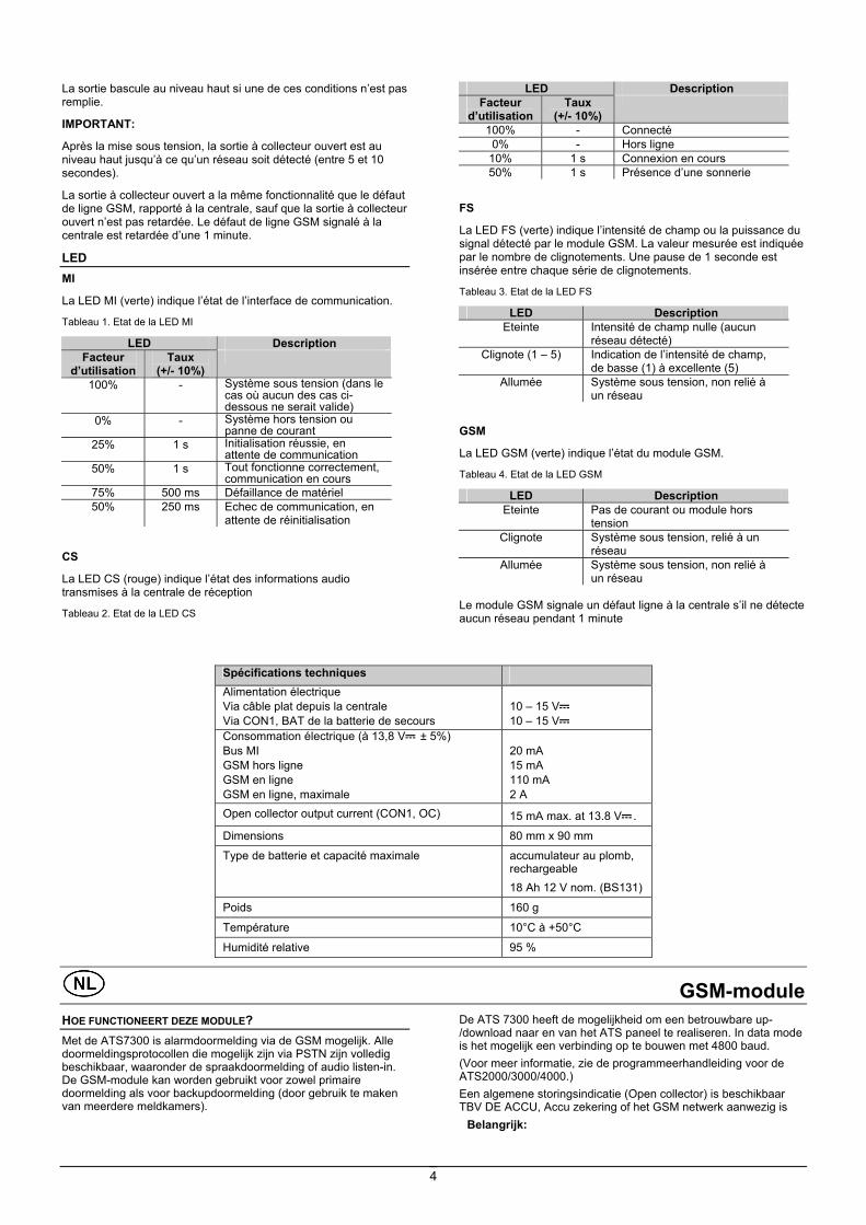
La sortie bascule au niveau haut si une de ces conditions n’est pas remplie.
IMPORTANT:
Après la mise sous tension, la sortie à collecteur ouvert est au niveau haut jusqu’à ce qu’un réseau soit détecté (entre 5 et 10 secondes).
La sortie à collecteur ouvert a la même fonctionnalité que le défaut de ligne GSM, rapporté à la centrale, sauf que la sortie à collecteur ouvert n’est pas retardée. Le défaut de ligne GSM signalé à la centrale est retardée d’une 1 minute.
LED MI
La LED MI (verte) indique l’état de l’interface de communication.
Tableau 1. Etat de la LED MI
LED Description Facteur
d’utilisation Taux
(+/- 10%)
100% - Système sous tension (dans le cas où aucun des cas ci-dessous ne serait valide)
0% - Système hors tension ou panne de courant
25% 1 s Initialisation réussie, en attente de communication
50% 1 s Tout fonctionne correctement, communication en cours
75% 500 ms Défaillance de matériel 50% 250 ms Echec de communication, en
attente de réinitialisation
CS
La LED CS (rouge) indique l’état des informations audio transmises à la centrale de réception
Tableau 2. Etat de la LED CS
LED Description Facteur
d’utilisation Taux
(+/- 10%)
100% - Connecté 0% - Hors ligne
10% 1 s Connexion en cours 50% 1 s Présence d’une sonnerie
FS
La LED FS (verte) indique l’intensité de champ ou la puissance du signal détecté par le module GSM. La valeur mesurée est indiquée par le nombre de clignotements. Une pause de 1 seconde est insérée entre chaque série de clignotements.
Tableau 3. Etat de la LED FS
LED Description Eteinte Intensité de champ nulle (aucun
réseau détecté) Clignote (1 – 5) Indication de l’intensité de champ,
de basse (1) à excellente (5) Allumée Système sous tension, non relié à
un réseau
GSM
La LED GSM (verte) indique l’état du module GSM.
Tableau 4. Etat de la LED GSM
LED Description Eteinte Pas de courant ou module hors
tension Clignote Système sous tension, relié à un
réseau Allumée Système sous tension, non relié à
un réseau Le module GSM signale un défaut ligne à la centrale s’il ne détecte aucun réseau pendant 1 minute
Spécifications techniques Alimentation électrique Via câble plat depuis la centrale Via CON1, BAT de la batterie de secours
10 – 15 V 10 – 15 V
Consommation électrique (à 13,8 V ± 5%) Bus MI GSM hors ligne GSM en ligne GSM en ligne, maximale
20 mA 15 mA 110 mA 2 A
Open collector output current (CON1, OC) 15 mA max. at 13.8 V .
Dimensions 80 mm x 90 mm Type de batterie et capacité maximale accumulateur au plomb,
rechargeable 18 Ah 12 V nom. (BS131)
Poids 160 g
Température 10°C à +50°C
Humidité relative 95 %
GSM-module HOE FUNCTIONEERT DEZE MODULE? Met de ATS7300 is alarmdoormelding via de GSM mogelijk. Alle doormeldingsprotocollen die mogelijk zijn via PSTN zijn volledig beschikbaar, waaronder de spraakdoormelding of audio listen-in. De GSM-module kan worden gebruikt voor zowel primaire doormelding als voor backupdoormelding (door gebruik te maken van meerdere meldkamers).
De ATS 7300 heeft de mogelijkheid om een betrouwbare up-/download naar en van het ATS paneel te realiseren. In data mode is het mogelijk een verbinding op te bouwen met 4800 baud. (Voor meer informatie, zie de programmeerhandleiding voor de ATS2000/3000/4000.) Een algemene storingsindicatie (Open collector) is beschikbaar TBV DE ACCU, Accu zekering of het GSM netwerk aanwezig is
Belangrijk:
5
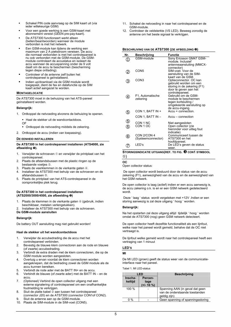
Schakel PIN code aanvraag op de SIM kaart uit (via ieder willekeurige GSM)
Voor een goede werking is een GSM-kaart met abonnement vereist (GEEN pre-pay-kaart).
De ATS7300 functioneert werkt alleen (bellen/beantwoorden) wanneer de module verbonden is met het netwerk.
Een GSM-module kan tijdens de werking een maximum van 2 A piekstroom vereisen. De accu die normaal verbonden is met het controlepaneel is nu ook verbonden met de GSM-module. De GSM-module controleert de accustatus en isoleert de accu wanneer de accuspanning onder de 9 volt daalt om de accu te beschermen (bescherming tegen diepe ontlading).
Controleer of de antenne zelf buiten het controlepaneel is geïnstalleerd.
Indien up/download via de GSM module wordt toegepast, dient de fax en datafunctie op de SIM kaart actief aangezet te worden.
MONTAGELOCATIE De ATS7300 moet in de behuizing van het ATS-paneel geïnstalleerd worden.
Belangrijk:
1. Ontkoppel de netvoeding alvorens de behuizing te openen.
Haal de stekker uit de wandcontactdoos. OF Ontkoppel de netvoeding middels de zekering.
2. Ontkoppel de accu (indien van toepassing).
DE EENHEID INSTALLEREN De ATS7300 in het controlepaneel installeren (ATS4000, zie afbeelding ).
1. Verwijder de schroeven en verwijder de printplaat van het controlepaneel.
2. Plaats de afstandsbussen met de plastic ringen op de bestaande voetjes .
3. Plaats de veerklemmen in de vierkante gaten . 4. Installeer de ATS7300 met behulp van de schroeven en de
afstandsbussen . 5. Plaats de printplaat van het ATS-controlepaneel in de
oorspronkelijke plek terug.
De ATS7300 in het controlepaneel installeren (ATS2000/3000/4500, zie afbeelding )
1. Plaats de klemmen in de vierkante gaten (gebruik, indien beschikbaar, metalen verlengstukken).
2. Installeer de ATS7300 met behulp van de schroeven. De GSM-module aansluiten
Belangrijk:
De battery OUT aansluiting mag niet gebruikt worden!
Haal de stekker uit het wandcontactdoos
1. Verwijder de accubedrading die de accu met het controlepaneel verbinden.
2. Bevestig de blauwe klem connectoren aan de rode en blauwe (of zwarte) accubedrading.
3. Verbindt de extra draden met de klem connectoren, die op de GSM module worden aangesloten.
4. Overtuig u ervan voordat de klem connectoren worden aangeknepen, dat de bedrading zowel de GSM module als de accu kunnen bereiken.
5. Verbindt de rode ader met de BATT IN+ en de accu. 6. Verbindt de blauwe (of zwarte ader) met de BATT IN – en de
accu. 7. (Optioneel) Verbind de open collector uitgang met een
externe signalering of controlepaneel om een onafhankelijke foutmelding te verkrijgen.
8. Sluit de platte kabel aan tussen het controlepaneel (connector J20) en de ATS7300 (connector CON1of CON2).
9. Sluit de antenne aan op de GSM-module. 10. Plaats de SIM-module in de SIM-voet (CON5).
11. Schakel de netvoeding in naar het controlepaneel en de GSM-module.
12. Controleer de veldsterkte (VS LED). Beweeg zonodig de antenne om het beste signaal te verkrijgen.
BESCHRIJVING VAN DE ATS7300 (ZIE AFBEELDING )
Nr. Beschrijving Functie
1 GSM-module Sony Ericsson GM47 GSM-module. Inclusief antenneaansluiting (MMCX-connector)
CON5 SIM-voet. Voor de aansluiting van de SIM-kaart van de GSM.
CON3 Optieconnector. OC kan gebruikt worden om een storing in de zekering (F1) door te geven aan het controlepaneel.
F1, Automatische zekering
Gebruikt om de GSM-module te beschermen tegen kortsluiting / omgekeerde aansluiting op de accu-ingang.
CON 1, BATT IN + Accu + connection.
CON 1, BATT IN – CON 1 NC CON 1 OC
Accu – connection Niet aangesloten Open collector (zie hieronder voor uitleg fout indicatie)
CON 2/CON 4 (Systeemconnector)
Communiceert tussen de ATS7300 en het hoofdpaneel.
LED’s De LED’s geven de status weer.
STORINGSINDICATIE UITGANG(REF. TO FIG. CON1 SYMBOOL )
OC Open collector status:
De open collector wordt bestuurd door de status van de accu zekering (F1), aanwezigheid van de accu en de aanwezigheid van het GSM netwerk.
De open collector is laag (actief) indien er een accu aanwezig is, de accu zekering o.k. is en er een GSM netwerk gedetecteerd wordt.
Deze ‘ laag ‘ status wordt vergeleken met +12V .Indien er een storing aanwezig is zal deze uitgang ‘ hoog ‘ worden.
Belangrijk:
Na het opstarten zal deze uitgang altijd tijdelijk ‘ hoog ‘ worden omdat de ATS7300 (nog) geen GSM netwerk detecteert. De open collector heeft dezelfde functionaliteit als een lijnfout, welke naar het paneel wordt gemeld, behalve dat de OC niet vertraagd is. De lijnfout welke gemeld wordt naar het controlepaneel heeft een vertraging van 1 minuut
LED’S MI
De MI LED (groen) geeft de status weer van de communicatie-interface naar het paneel.
Tabel 1. MI LED-status
LED Beschrijving Inscha-keltijd
Percen-tage
(+/- 10 %)
100 % - Spanning AAN (in geval dat geen van de onderstaande toestanden geldig zijn)
0 % - Geen spanning of spanningsstoring
6
LED Beschrijving Inscha-keltijd
Percen-tage
(+/- 10 %)
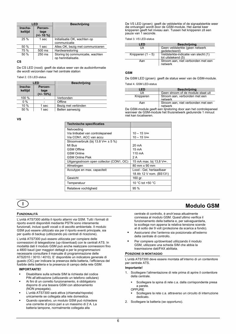
25 % 1 sec Initialisatie OK, wachten op communicatie
50 % 1 sec Alles OK, bezig met communiceren 75 % 500 ms Hardwarestoring 50 % 250 ms Storing bij communicatie, wachten
op herinitialisatie. CS
De CS LED (rood) geeft de status weer van de audioinformatie die wordt verzonden naar het centrale station
Tabel 2. CS LED-status
LED Beschrijving Inscha-keltijd
Percen-tage
(+/- 10%)
100 % - Verbonden 0 % - Offline
10 % 1 sec Bezig met verbinden 50 % 1 sec Bellen aanwezig
VS
De VS LED (groen) geeft de veldsterkte of de signaalsterkte weer die ontvangen wordt door de GSM-module. Het aantal keer knipperen geeft het niveau aan. Tussen het knipperen zit een pauze van 1 seconde.
Tabel 3. VS LED-status
LED Beschrijving Uit Geen veldsterkte (geen netwerk
gedetecteerd) Knipperen (1 – 5) Veldsterkte-indicatie van slecht (1)
tot uitstekend (5) Aan Stroom aan, niet verbonden met een
netwerk GSM De GSM LED (groen) geeft de status weer van de GSM-module.
Tabel 4. GSM LED-status
LED Beschrijving Uit Geen stroom of de module staat uit
Knipperen Stroom aan, verbonden met een netwerk
Aan Stroom aan, niet verbonden met een netwerk
De GSM-module geeft een lijnstoring door aan het controlepaneel wanneer de GSM-module het thuisnetwerk gedurende 1 minuut niet kan localiseren.
Technische specificaties Netvoeding Via lintkabel van controlepaneel Via CON1, ACC van accu
10 – 15 V 10 – 15 V
Stroomverbruik (bij 13.8 V ± 5 %) MI Bus GSM Offline GSM Online GSM Online Piek
20 mA 15 mA 110 mA 2 A
Uitgangsstroom open collector (CON1, OC) 15 mA max. bij 13,8 V . Afmetingen 80 mm x 90 mm Accutype en max. capaciteit Lood - Gel, herlaadbaar
18 Ah 12 V nom. (BS131) Gewicht 160 gr. Temperatuur 10 °C tot +50 °C
Relatieve vochtigheid 95 %
Modulo GSM FUNZIONALITÀ L’unità ATS7300 abilita il riporto allarmi via GSM. Tutti i formati di riporto eventi disponibili mediante PSTN sono interamente funzionali, inclusi quelli vocali o di ascolto ambientale. Il modulo GSM può essere utilizzato sia per il riporto eventi principale, sia per quello di backup (utilizzando più centrali di ricezione). L’unità ATS7300 può essere utilizzata per compiere delle connessioni di telegestione (up-/download) con le centrali ATS. In modalità dati il modulo GSM può anche realizzare connessioni fino a 4800 baud (per maggiori dettagli e per le programmazioni necessarie consultare il manuale di programmazione delle ATS2010 / 3010 / 4010). E’ disponibile un indicatore generale di guasto (OC) per indicare la presenza della batteria, l’efficienza del fusibile della batteria e la presenza di campo della rete GSM.
IMPORTANTE! Disabilitare sulla scheda SIM la richiesta del codice
PIN all’attivazione (utilizzando un telefono cellulare) Ai fini di un corretto funzionamento, è obbligatorio
disporre di una tessera GSM con abbonamento (NON prepagata).
L’unità ATS7300 sarà attiva (chiamata/risposta) unicamente se collegata alla rete domestica.
Quando operativo, un modulo GSM può richiedere una corrente di picco pari a un massimo di 2 A. La batteria tampone, normalmente collegata alla
centrale di controllo, è anch’essa attualmente connessa al modulo GSM. Quest’ultimo verifica il funzionamento della batteria e, per salvaguardarla, la scollega non appena la relativa tensione scende al di sotto dei 9 volt (protezione da scarica a fondo).
Assicurarsi che l’antenna sia posizionata all’esterno della centrale di controllo.
Per compiere up/download utilizzando il modulo GSM, utilizzare una scheda SIM che abbia la trasmissione dati/FAX abilitata.
POSIZIONE DI MONTAGGIO L’unità ATS7300 deve essere montata all’interno di un contenitore per centrale ATS. Importante! 1. Scollegare l’alimentazione di rete prima di aprire il contenitore
della centrale.
Scollegare la spina di rete c.a. dalla corrispondente presa a parete.
OPPURE Scollegare la rete c.a. attraverso un circuito di interruzione
dedicato. 2. Scollegare la batteria (se opportuno).
7
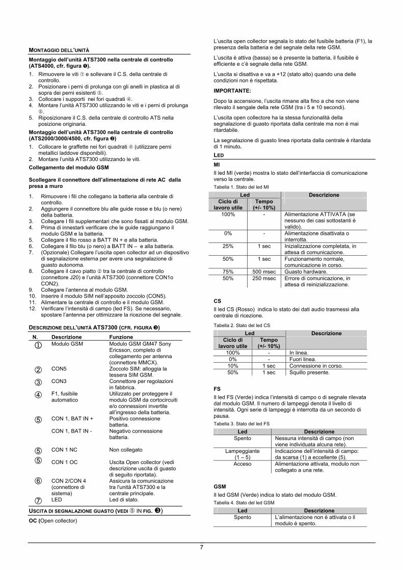
MONTAGGIO DELL’UNITÀ Montaggio dell’unità ATS7300 nella centrale di controllo (ATS4000, cfr. figura ). 1. Rimuovere le viti e sollevare il C.S. della centrale di
controllo. 2. Posizionare i perni di prolunga con gli anelli in plastica al di
sopra dei perni esistenti . 3. Collocare i supporti nei fori quadrati . 4. Montare l’unità ATS7300 utilizzando le viti e i perni di prolunga
. 5. Riposizionare il C.S. della centrale di controllo ATS nella
posizione originaria. Montaggio dell’unità ATS7300 nella centrale di controllo (ATS2000/3000/4500, cfr. figura ) 1. Collocare le graffette nei fori quadrati (utilizzare perni
metallici laddove disponibili). 2. Montare l’unità ATS7300 utilizzando le viti. Collegamento del modulo GSM
Scollegare il connettore dell’alimentazione di rete AC dalla presa a muro
1. Rimuovere i fili che collegano la batteria alla centrale di controllo.
2. Aggiungere il connettore blu alle guide rosse e blu (o nere) della batteria.
3. Collegare I fili supplementari che sono fissati al modulo GSM. 4. Prima di innestarli verificare che le guide raggiungano il
modulo GSM e la batteria. 5. Collegare il filo rosso a BATT IN + e alla batteria. 6. Collegare il filo blu (o nero) a BATT IN – e alla batteria. 7. (Opzionale) Collegare l’uscita open collector ad un dispositivo
di segnalazione esterna per avere una segnalazione di guasto autonoma.
8. Collegare il cavo piatto tra la centrale di controllo (connettore J20) e l’unità ATS7300 (connettore CON1o CON2).
9. Collegare l’antenna al modulo GSM. 10. Inserire il modulo SIM nell’apposito zoccolo (CON5). 11. Alimentare la centrale di controllo e il modulo GSM. 12. Verificare l’intensità di campo (led FS). Se necessario,
spostare l’antenna per ottimizzare la ricezione del segnale. DESCRIZIONE DELL’UNITÀ ATS7300 (CFR. FIGURA )
N. Descrizione Funzione
1 Modulo GSM Modulo GSM GM47 Sony Ericsson, completo di collegamento per antenna (connettore MMCX).
CON5 Zoccolo SIM: alloggia la tessera SIM GSM.
CON3 Connettore per regolazioni in fabbrica.
F1, fusibile automatico
Utilizzato per proteggere il modulo GSM da cortocircuiti e/o connessioni invertite all’ingresso della batteria.
CON 1, BAT IN + Positivo connessione batteria.
CON 1, BAT IN - Negativo connessione batteria.
CON 1 NC CON 1 OC CON 2/CON 4 (connettore di sistema)
Non collegato Uscita Open collector (vedi descrizione uscita di guasto di seguito riportata). Assicura la comunicazione tra l'unità ATS7300 e la centrale principale.
LED Led di stato.
USCITA DI SEGNALAZIONE GUASTO (VEDI IN FIG. ) OC (Open collector)
L’uscita open collector segnala lo stato del fusibile batteria (F1), la presenza della batteria e del segnale della rete GSM.
L’uscita è attiva (bassa) se è presente la batteria, il fusibile è efficiente e c’è segnale della rete GSM.
L’uscita si disattiva e va a +12 (stato alto) quando una delle condizioni non è rispettata.
IMPORTANTE:
Dopo la accensione, l’uscita rimane alta fino a che non viene rilevato il sengale della rete GSM (tra i 5 e 10 secondi).
L’uscita open collectore ha la stessa funzionalità della segnalazione di guasto riportata dalla centrale ma non è mai ritardabile.
La segnalazione di guasto linea riportata dalla centrale è ritardata di 1 minuto. LED MI Il led MI (verde) mostra lo stato dell’interfaccia di comunicazione verso la centrale. Tabella 1. Stato del led MI
Led Descrizione Ciclo di
lavoro utile Tempo
(+/- 10%)
100% - Alimentazione ATTIVATA (se nessuno dei casi sottostanti è valido).
0% - Alimentazione disattivata o interrotta.
25% 1 sec Inizializzazione completata, in attesa di comunicazione.
50% 1 sec Funzionamento normale, comunicazione in corso.
75% 500 msec Guasto hardware. 50% 250 msec Errore di comunicazione, in
attesa di reinizializzazione.
CS Il led CS (Rosso) indica lo stato dei dati audio trasmessi alla centrale di ricezione.
Tabella 2. Stato del led CS Led Descrizione
Ciclo di lavoro utile
Tempo (+/- 10%)
100% - In linea. 0% - Fuori linea.
10% 1 sec Connessione in corso. 50% 1 sec Squillo presente.
FS Il led FS (Verde) indica l’intensità di campo o di segnale rilevata dal modulo GSM. Il numero di lampeggi denota il livello di intensità. Ogni serie di lampeggi è interrotta da un secondo di pausa. Tabella 3. Stato del led FS
Led Descrizione Spento Nessuna intensità di campo (non
viene individuata alcuna rete). Lampeggiante
(1 – 5) Indicazione dell’intensità di campo: da scarsa (1) a eccellente (5).
Acceso Alimentazione attivata, modulo non collegato a una rete.
GSM Il led GSM (Verde) indica lo stato del modulo GSM. Tabella 4. Stato del led GSM
Led Descrizione Spento L’alimentazione non è attivata o il
modulo è spento.
8
Led Descrizione Lampeggiante Alimentazione attivata, modulo
collegato a una rete. Acceso Alimentazione attivata, modulo non
collegato a una rete.
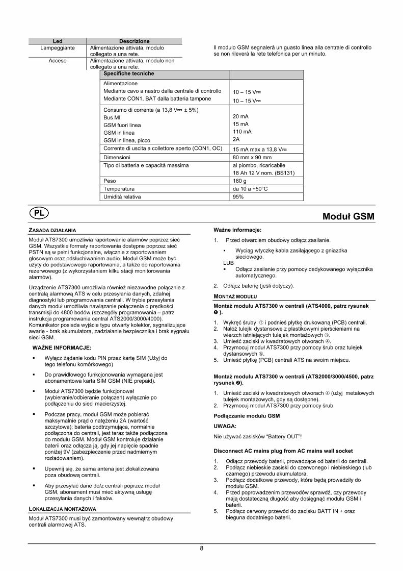
Il modulo GSM segnalerà un guasto linea alla centrale di controllo se non rileverà la rete telefonica per un minuto.
Specifiche tecniche Alimentazione Mediante cavo a nastro dalla centrale di controllo Mediante CON1, BAT dalla batteria tampone
10 – 15 V 10 – 15 V
Consumo di corrente (a 13,8 V ± 5%) Bus MI GSM fuori linea GSM in linea GSM in linea, picco
20 mA 15 mA 110 mA 2A
Corrente di uscita a collettore aperto (CON1, OC) 15 mA max a 13,8 V Dimensioni 80 mm x 90 mm Tipo di batteria e capacità massima al piombo, ricaricabile
18 Ah 12 V nom. (BS131) Peso 160 g Temperatura da 10 a +50°C Umidità relativa 95%
Moduł GSM ZASADA DZIAŁANIA Moduł ATS7300 umożliwia raportowanie alarmów poprzez sieć GSM. Wszystkie formaty raportowania dostępne poprzez sieć PSTN są w pełni funkcjonalne, włącznie z raportowaniem głosowym oraz odsłuchiwaniem audio. Moduł GSM może być użyty do podstawowego raportowania, a także do raportowania rezerwowego (z wykorzystaniem kilku stacji monitorowania alarmów).
Urządzenie ATS7300 umożliwia również niezawodne połącznie z centralą alarmową ATS w celu przesyłania danych, zdalnej diagnostyki lub programowania centrali. W trybie przesyłania danych moduł umożliwia nawiązanie połączenia o prędkości transmisji do 4800 bodów (szczegóły programowania – patrz instrukcja programowania central ATS2000/3000/4000). Komunikator posiada wyjście typu otwarty kolektor, sygnalizujące awarię - brak akumulatora, zadziałanie bezpiecznika i brak sygnału sieci GSM.
WAŻNE INFORMACJE: Wyłącz żądanie kodu PIN przez kartę SIM (Użyj do
tego telefonu komórkowego)
Do prawidłowego funkcjonowania wymagana jest abonamentowa karta SIM GSM (NIE prepaid).
Moduł ATS7300 będzie funkcjonował (wybieranie/odbieranie połączeń) wyłącznie po podłączeniu do sieci macierzystej.
Podczas pracy, moduł GSM może pobierać maksymalnie prąd o natężeniu 2A (wartość szczytowa); bateria podtrzymująca, normalnie podłączona do centrali, jest teraz także podłączona do modułu GSM. Moduł GSM kontroluje działanie baterii oraz odłącza ją, gdy jej napięcie spadnie poniżej 9V (zabezpieczenie przed nadmiernym rozładowaniem).
Upewnij się, że sama antena jest zlokalizowana poza obudową centrali.
Aby przesyłać dane do/z centrali poprzez moduł GSM, abonament musi mieć aktywną usługę przesyłania danych i faksów.
LOKALIZACJA MONTAŻOWA Moduł ATS7300 musi być zamontowany wewnątrz obudowy centrali alarmowej ATS.
Ważne informacje:
1. Przed otwarciem obudowy odłącz zasilanie.
Wyciąg wtyczkę kabla zasilającego z gniazdka sieciowego.
LUB Odłącz zasilanie przy pomocy dedykowanego wyłącznika
automatycznego.
2. Odłącz baterię (jeśli dotyczy).
MONTAŻ MODUŁU Montaż modułu ATS7300 w centrali (ATS4000, patrz rysunek
).
1. Wykręć śruby i podnieś płytkę drukowaną (PCB) centrali. 2. Nałóż tulejki dystansowe z plastikowymi pierścieniami na
wierzch istniejących tulejek montażowych . 3. Umieść zaciski w kwadratowych otworach . 4. Przymocuj moduł ATS7300 przy pomocy śrub oraz tulejek
dystansowych . 5. Umieść płytkę (PCB) centrali ATS na swoim miejscu.
Montaż modułu ATS7300 w centrali (ATS2000/3000/4500, patrz rysunek ).
1. Umieść zaciski w kwadratowych otworach (użyj metalowych tulejek montażowych, gdy są dostępne).
2. Przymocuj moduł ATS7300 przy pomocy śrub. Podłączanie modułu GSM
UWAGA:
Nie używać zasisków “Battery OUT”!
Disconnect AC mains plug from AC mains wall socket
1. Odłącz przewody baterii, prowadzące od baterii do centrali. 2. Podłącz niebieskie zasiski do czerwonego i niebieskiego (lub
czarnego) przewodu akumulatora. 3. Podłącz dodatkowe przewody, które będą prowadziły do
modułu GSM. 4. Przed poprowadzenim przewodów sprawdź, czy przewody
mają dostateczną długość aby dosięgnąć modułu GSM i baterii.
5. Podłącz cerwony przewód do zacisku BATT IN + oraz bieguna dodatniego baterii.

9
6. Podłącz niebieski (lub czarny) przewód do zacisku BATT IN - oraz bieguna ujemnego baterii.
7. (Opcjonalnie) Podłącz wyjście sygnalizacyjne do zewnętrznego urządzenia sygnalizacyjnego lub centrali alarmowej, aby uzyskać niezależną sygnalizację awarii.
8. Podłącz płaski kabel pomiędzy centralą (złączka J20) a modułem ATS7300 (złączka CON1 lub CON2).
9. Podłącz antenę do modułu GSM. 10. Umieść kartę SIM w gnieździe (CON5). 11. Włącz zasilanie centrali oraz modułu GSM. 12. Sprawdź siłę sygnału GSM (dioda LED o symbolu FS). Gdy
zachodzi taka konieczność, ustaw antenę tak, by uzyskać najsilniejszy sygnał.
OPIS MODUŁU ATS7300 (PATRZ RYSUNEK )
Nr Opis Funkcja
1 Moduł GSM Moduł GSM Sony Ericsson GM47 Obejmuje złaczkę antenową (złączka MMCX)
CON5 Gniazdo SIM.
CON3 Złącze dodatkowe. Używane tylko w trakcie produkcji.
F1, wyłącznik automatyczny
Używany do zabezpieczenia modułu GSM przed zwarciem/odwrotnym podłączeniem baterii.
CON 1, BAT IN + Biegun + akumulatora.
CON 1, BAT OUT - Biegun – akumulatora CON 1 NC Niepodłączony.
CON 1 CO Wyjście Alarmowe typu otwarty kolektor (Patr opis poniżej)
CON 2/CON 4 (złączka systemowa)
Komunikacja pomiędzy ATS7300 oraz centralą.
Diody LED Wskazują stan użądzenia.
WYJŚCIE SYGNALIZACYJNE (PATRZ RYS. CON1 SYMBOL ) OC Stan wyjścia: Wyjście sygnalizacyjne jest sterowane zależnie od stanu bezpiecznia baterii F1, braku akumulatora i braku sygnału GSM. Wyjście jest w stanie niskim (aktywne), jeśli jest podłączony akumulator, bezpieczniek F1nie jest aktywny oraz sygnał GSM jest wykrywany przez urządzenie. Wyjście w stanie niskim może pobierać prąd i jest porównywane do napięcia +12V w stanie wysokim. Wyjście jest w stanie wysokim wrazie jakiejkolwiek awarii. UWAGA! Zaraz po uruchomieniu wyjście sygnalizacyjne jest zawsze w stanie wysokim, ponieważ ATS7300 musi najpierw wykryć sygnał sieci GSM. Wyjście sygnalizacyjne ma taką samą funkcjonalność, co „Błąd linii” raportowany do centrali alarmowej. Z tą różnicą, że wyjście nie jest opóźnione. „BŁĄD LINII” JEST RAPORTOWANY DO CENTRALI ALARMOWEJ Z OPÓŹNIENIEM OK. 1 MINUTY. DIODY LED Dioda MI
Dioda MI (zielona) wskazuje stan interfejsu komunikacyjnego do centrali alarmowej. Tabela 1. Stan diody MI
LED Opis Cykl
pracy Szybkość (+/- 10%)
100% - Zasilanie jest WŁĄCZONE (w przypadku, gdy nie zachodzi żaden z poniższych przypadków)
0% - Brak zasilania lub zasilanie wyłączone.
25% 1 sek Inicjalizacja OK, oczekiwanie na komunikację
50% 1 sek Wszystko OK, komunikacja działa 75% 500 ms Błąd sprzętowy 50% 250 ms Błąd komunikacji, oczekiwanie na
ponowną inicjalizację.
Dioda CS
Dioda CS (Czerwona) wskazuje stan informacji audio, przesyłanych do centrali alarmowej.
Tabela 2. Stan diody CS
LED Opis Cykl
pracy Szybkość (+/- 10%)
100% - Połączony 0% - Offline (bez połączenia)
10% 1 sek Łączenie 50% 1 sek Dzwonienie
Dioda FS
Dioda FS (Zielona) wskazuje siłę sygnału pola lub sygnału GSM odbieranego przez moduł GSM. Liczba mignięć wskazuje siłę sygnału. Pomiędzy każdym zestawem mignięć występuje 1-sekundowa przerwa. Tabela 3. Stan diody FS
LED Opis Wyłączona Nie wykryto sygnału GSM.
Mignięcia (1-5) Wskazanie siły sygnału od słabego (1) do silnego (5).
Włączona Zasilanie włączone, bez podłączenia do sieci.
Dioda GSM
Dioda GSM (Zielona) wskazuje stan modułu GSM.
Tabela 4. Stan diody GSM
LED Opis Wyłączona Brak zasilania lub moduł jest
wyłączony. Miga Zasilanie włączone, podłączenie do
sieci. Włączona Zasilanie włączone, bez podłączenia
do sieci. Moduł GSM będzie sygnalizował awarię linii do centrali, jeśli w ciągu 1 minuty nie zostanie wykryty sygnał sieci macierzystej.
Specyfikacje techniczne Zasilanie Przy pomocy taśmy z centrali Poprzez CON1, BAT z baterii podtrzymującej
10 – 15 VDC 10 – 15 VDC
Pobór prądu (przy 13.8 VDC ± 5%)
10
Magistrala MI GSM Offline GSM Online GSM Online (szczytowy)
20 mA 15 mA 110 mA 2A
Prąd wyjściowy układu z otwartym kolektorem (CON3, OC) 15 mA max. przy 13.8 VDC. Zasilanie bateryjne (CON1, + i -) NIE UŻYWAĆ Wymiary 80 mm x 90 mm Typ baterii oraz pojemność maksymalna Kwasowo-ołowiowa, z możliwością ładowania
18 Ah 12 V nominalnie (BS131) Waga 160 g Temperatura od 10°C do +50°C
Wigotność względna 95 %
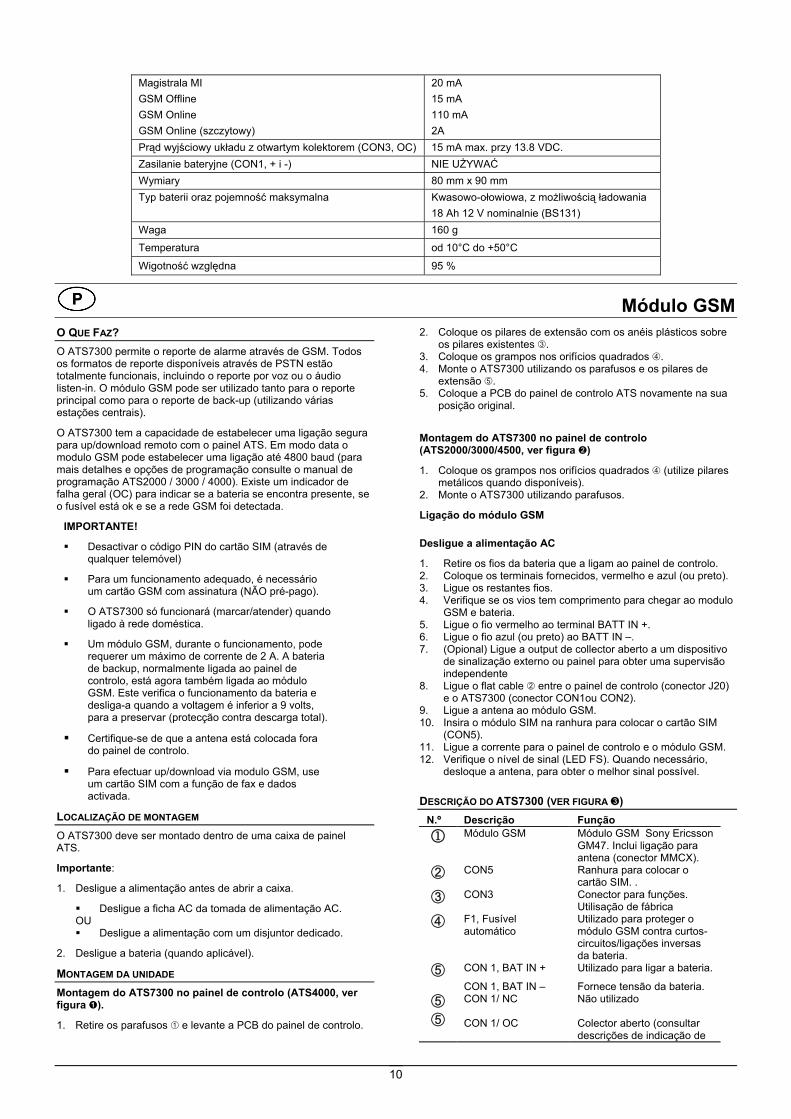
Módulo GSMO QUE FAZ? O ATS7300 permite o reporte de alarme através de GSM. Todos os formatos de reporte disponíveis através de PSTN estão totalmente funcionais, incluindo o reporte por voz ou o áudio listen-in. O módulo GSM pode ser utilizado tanto para o reporte principal como para o reporte de back-up (utilizando várias estações centrais).
O ATS7300 tem a capacidade de estabelecer uma ligação segura para up/download remoto com o painel ATS. Em modo data o modulo GSM pode estabelecer uma ligação até 4800 baud (para mais detalhes e opções de programação consulte o manual de programação ATS2000 / 3000 / 4000). Existe um indicador de falha geral (OC) para indicar se a bateria se encontra presente, se o fusível está ok e se a rede GSM foi detectada.
IMPORTANTE!
Desactivar o código PIN do cartão SIM (através de qualquer telemóvel)
Para um funcionamento adequado, é necessário um cartão GSM com assinatura (NÃO pré-pago).
O ATS7300 só funcionará (marcar/atender) quando ligado à rede doméstica.
Um módulo GSM, durante o funcionamento, pode requerer um máximo de corrente de 2 A. A bateria de backup, normalmente ligada ao painel de controlo, está agora também ligada ao módulo GSM. Este verifica o funcionamento da bateria e desliga-a quando a voltagem é inferior a 9 volts, para a preservar (protecção contra descarga total).
Certifique-se de que a antena está colocada fora do painel de controlo.
Para efectuar up/download via modulo GSM, use um cartão SIM com a função de fax e dados activada.
LOCALIZAÇÃO DE MONTAGEM O ATS7300 deve ser montado dentro de uma caixa de painel ATS.
Importante:
1. Desligue a alimentação antes de abrir a caixa.
Desligue a ficha AC da tomada de alimentação AC. OU Desligue a alimentação com um disjuntor dedicado.
2. Desligue a bateria (quando aplicável).
MONTAGEM DA UNIDADE Montagem do ATS7300 no painel de controlo (ATS4000, ver figura ).
1. Retire os parafusos e levante a PCB do painel de controlo.
2. Coloque os pilares de extensão com os anéis plásticos sobre os pilares existentes .
3. Coloque os grampos nos orifícios quadrados . 4. Monte o ATS7300 utilizando os parafusos e os pilares de
extensão . 5. Coloque a PCB do painel de controlo ATS novamente na sua
posição original.
Montagem do ATS7300 no painel de controlo (ATS2000/3000/4500, ver figura )
1. Coloque os grampos nos orifícios quadrados (utilize pilares metálicos quando disponíveis).
2. Monte o ATS7300 utilizando parafusos. Ligação do módulo GSM
Desligue a alimentação AC
1. Retire os fios da bateria que a ligam ao painel de controlo. 2. Coloque os terminais fornecidos, vermelho e azul (ou preto). 3. Ligue os restantes fios. 4. Verifique se os vios tem comprimento para chegar ao modulo
GSM e bateria. 5. Ligue o fio vermelho ao terminal BATT IN +. 6. Ligue o fio azul (ou preto) ao BATT IN –. 7. (Opional) Ligue a output de collector aberto a um dispositivo
de sinalização externo ou painel para obter uma supervisão independente
8. Ligue o flat cable entre o painel de controlo (conector J20) e o ATS7300 (conector CON1ou CON2).
9. Ligue a antena ao módulo GSM. 10. Insira o módulo SIM na ranhura para colocar o cartão SIM
(CON5). 11. Ligue a corrente para o painel de controlo e o módulo GSM. 12. Verifique o nível de sinal (LED FS). Quando necessário,
desloque a antena, para obter o melhor sinal possível. DESCRIÇÃO DO ATS7300 (VER FIGURA )
N.º Descrição Função
1 Módulo GSM Módulo GSM Sony Ericsson GM47. Inclui ligação para antena (conector MMCX).
CON5 Ranhura para colocar o cartão SIM. .
CON3 Conector para funções. Utilisação de fábrica
F1, Fusível automático
Utilizado para proteger o módulo GSM contra curtos-circuitos/ligações inversas da bateria.
CON 1, BAT IN + Utilizado para ligar a bateria.
CON 1, BAT IN – CON 1/ NC CON 1/ OC
Fornece tensão da bateria. Não utilizado Colector aberto (consultar descrições de indicação de

11
N.º Descrição Função outputs de falha)
CON 2/CON 4 (conector do sistema)
Faz a comunicação entre o ATS7300 e o painel principal.
LED LEDs que indicam o estado.
OUTPUT DE INDICAÇÃO DE FALHA (REF. TO IN FIG. ) OC (Colector Aberto) O colector aberto é controlado pelo estado do fusível da bateria (F1), presença da bateria e de rede GSM.
A saída encontra-se em estado ‘low’ (activa) se a bateria se encontrar presente, o fusível ok e rede GSm detectada.
Este estado ‘low’ é em comparação com + 12V. Em condição de erro esta ouput é ‘high’.
IMPORTANTE:
Após arranque, a output de collector aberto irá manter-se em ‘high’ até que a rede GSM seja detectad (entre 5 a 10 segundos).
A output collector aberto tem a mesma funcionalidade que a falha de linha, que reporta para o painel, a diferença é que a OC não sofre retardo.
A falha de linha reportada para o painel tem, um retardo de 1 minuto.
LED MI O LED MI (verde) indica o estado do interface de comunicação com o painel.
Quadro 1. Estado do LED MI LED Descrição
Ciclo de apareci-mento
Velocidade (+/- 10%)
100% - Alimentação ON (caso nenhum dos casos seguintes seja válido)
0% - Sem alimentação ou falha de alimentação
25% 1 seg. Inicialização OK, a aguardar comunicação
50% 1 seg. Tudo OK, comunicação em curso
75% 500 ms Falha do hardware 50% 250 ms Falha na comunicação, a
aguardar reinicialização.
CS O LED CS(Vermelho) indica o estado da informação áudio transmitida à estação central
Quadro 2. Estado do LED CS
LED Descrição Ciclo de apareci-mento
Velocidade (+/- 10%)
100% - Ligada 0% - Offline
10% 1 seg. A ligar 50% 1 seg. A tocar
FS O LED FS (verde) indica o nível de sinalencontrado pelo módulo GSM. O número de sinais intermitentes indica o nível. Entre cada conjunto de sinais intermitentes é inserida uma pausa de 1 segundo.
Quadro 3. Estado do LED FS
LED Descrição Desligado Sem sinal (nenhuma rede
detectada)
LED Descrição
CON 2/CON 4 (conector do sistema)
Faz a comunicação entre o ATS7300 e o painel principal.
LED LEDs que indicam o estado.
OUTPUT DE INDICAÇÃO DE FALHA (REF. TO IN FIG. ) OC (Colector Aberto) O colector aberto é controlado pelo estado do fusível da bateria (F1), presença da bateria e de rede GSM.
A saída encontra-se em estado ‘low’ (activa) se a bateria se encontrar presente, o fusível ok e rede GSm detectada.
Este estado ‘low’ é em comparação com + 12V. Em condição de erro esta ouput é ‘high’.
IMPORTANTE:
Após arranque, a output de collector aberto irá manter-se em ‘high’ até que a rede GSM seja detectad (entre 5 a 10 segundos).
A output collector aberto tem a mesma funcionalidade que a falha de linha, que reporta para o painel, a diferença é que a OC não sofre retardo.
A falha de linha reportada para o painel tem, um retardo de 1 minuto.
LED MI O LED MI (verde) indica o estado do interface de comunicação com o painel.
Quadro 1. Estado do LED MI LED Descrição
Ciclo de apareci-mento
Velocidade (+/- 10%)
100% - Alimentação ON (caso nenhum dos casos seguintes seja válido)
0% - Sem alimentação ou falha de alimentação
25% 1 seg. Inicialização OK, a aguardar comunicação
50% 1 seg. Tudo OK, comunicação em curso
75% 500 ms Falha do hardware 50% 250 ms Falha na comunicação, a
aguardar reinicialização.
CS O LED CS(Vermelho) indica o estado da informação áudio transmitida à estação central
Quadro 2. Estado do LED CS
LED Descrição Ciclo de apareci-mento
Velocidade (+/- 10%)
100% - Ligada 0% - Offline
10% 1 seg. A ligar 50% 1 seg. A tocar
FS O LED FS (verde) indica o nível de sinalencontrado pelo módulo GSM. O número de sinais intermitentes indica o nível. Entre cada conjunto de sinais intermitentes é inserida uma pausa de 1 segundo.
Quadro 3. Estado do LED FS
LED Descrição Desligado Sem sinal (nenhuma rede
detectada)

12
LED Descrição Intermitente (1 – 5) Indicação nível de sinal, de má (1) a
excelente (5) Ligado Alimentação ligada, não estando
ligado a uma rede
GSM O LED GSM (verde) indica o estado do módulo GSM.
Quadro 4. Estado do LED GSM
LED Descrição Desligado Não há alimentação ou o módulo
está desligado Intermitente Alimentação ligada, ligado a uma
rede Ligado Alimentação ligada, não estando
ligado a uma rede
O módulo GSM assinalará uma falha de linha para o painel de controlo se o módulo GSM não detectar a rede doméstica no período de 1 minuto.
Especificações técnicas Alimentação Através de flat cable do painel de controlo Através de CON1, BAT da bateria de backup
10 – 15 V 10 – 15 V
Consumo (a 13,8 V ± 5%) MI Bus GSM Offline GSM Online Máximo em GSM Online
20 mA 15 mA 110 mA 2 A
Corrente de output de colector aberto (CON1, OC)
15 mA máx. a 13,8 V .
Dimensões 80 mm x 90 mm Tipo de bateria e capacidade máxima de chumbo ácido
recarregável 18 Ah 12 V nom. (BS131)
Peso 160 g
Temperatura de 10° C a +50° C
Humidade relativa 95 %
GSM-modul FUNKSJONSMÅTE ATS7300 gjør det mulig å foreta alarmrapportering via GSM. Alle tilgjengelige rapporteringsformater via PSTN fungerer fullt ut, iberegnet talerapportering eller audiolytting. GSM-modulen kan brukes både til hovedrapportering og nødsrapportering (når det benyttes flere alarmmottak).
ATS7300 tillater også fjernprogrammering av ATS sentralapparatet. I data modus støttes dataoverføring opptil 4800 baud (for mer informasjon og programmering se ATS2000 / 3000 / 4000 Programmeringsmanual). En felles feilutgang vil aktiveres ved batterifeil, sikeringsfeil og manglende GSM nettverk.
VIKTIG: Deaktiver PIN kode kontroll av SIM kortet (fra en
mobiltelefon)
Bruk et GSM-kort med abonnement (IKKE kontantkort).
ATS7300 fungerer bare (oppringning/svar) hvis det er koblet til hjemmenettet.
En GSM-modul i drift kan trenge maksimalt 2 A toppstrøm. Reservebatteriet som normalt er koblet til sentralapparatet, er nå også koblet til GSM-modulen. GSM-modulen kontrollerer at batteriet fungerer riktig og kobler det fra for å beskytte det dersom batterispenningen faller under 9 volt
(beskyttelse mot full utladning)
Kontroller at antennen er plassert utenfor sentralapparatet.
For fjernprogrammering via GSM modulen må et SIM kort som er data/fax kompatibelt benyttes.
MONTERINGSPLASSERING ATS7300 må monteres i et ATS-sentralkabinett.
Viktig:
1. Nettstrømmen må kobles fra før kabinettet åpnes.
Koble AC-nettstøpselet fra AC-veggkontakten. ELLER Koble fra nettstrømmen med en dedikert strømbryter.
2. Koble fra batteriet (hvis dette finnes).
MONTERING AV ENHETEN Montering av ATS7300 i sentralapparatet (ATS4000, se figur
).
1. Fjern skruene , og løft av sentralapparat- kretskortet. 2. Sett avstandsstykkene med plastringene oppå de eksisterende
pilarene . 3. Sett klypene inn i firkanthullene . 4. Monter ATS7300 med skruene og avstandsstykkene . 5. Sett ATS sentralapparat- kretskortet tilbake i opprinnelig
stilling.
13
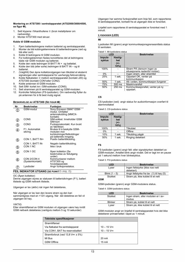
Montering av ATS7300 i sentralapparatet (ATS2000/3000/4500, se figur ).
1. Sett klypene i firkanthullene (bruk metallpilarer om nødvendig).
2. Monter ATS7300 med skruer. Koble til GSM-modulen
1. Fjern batteriledningene mellom batteriet og sentralapparatet. 2. Monter de blå koblingsklemmene til batteriledningene (rød og
blå eller sort) 3. Koble til ledningene til GSM modulen. 4. For kolbingsklemmen festes konotrlleres det at ledningene
både når GSM modulen og batteriet. 5. Koble den røde ledningen til BATT IN + og battetiet. 6. Koble den blå (eller sorte) ledningen til BATT IN – og til
batteriet. 7. (Valgfritt) Den åpne kollektorutgangen kan tilkoblet et eksternt
signalorgan eller sentralapparat for uavhengig feilovervåking. 8. Koble flatkabelen mellom sentralapparatet (kontakt J20) og
ATS7300 (kontakt CON1eller CON2). 9. Koble antennen til GSM-modulen. 10. Sett SIM- kortet inn i SIM-sokkelen (CON5). 11. Sett strømmen på til sentralapparatet og GSM-modulen. 12. Kontroller feltstyrken (FS-lysdioden). Om nødvendig flytter du
på antennen for å få best mulig signal. BESKRIVELSE AV ATS7300 (SE FIGUR )
Nr. Beskrivelse Funksjon
1 GSM-modul Sony Ericsson GM47 GSM-modul. Omfatter antennekobling (MMCX-kontakt)
CON5 SIM-sokkel. Inneholder GSM SIM-kort
CON3 Funksjonskontakt. Kun brukt av fabrikken.
F1, Automatisk sikring
Brukes til å beskytte GSM-modulen mot kortslutninger/feilkoblinger på batteriets inngang.
CON 1, BATT IN+ Positiv batteritilkobling.
CON 1, BATT IN- Negativ batteritilkobling.
CON 1 NC
Ikke i bruk
CON 1 OC Åpen kollektor (Se beskrivelse av feilutgang under)
CON 2/CON 4 (Systemkontakt)
Kommuniserer mellom ATS7300 og hovedapparatet.
Lysdioder Angir funksjonsstatus.
FEIL INDIKATOR UTGANG (SE PUNKT I FIG. ) OC (Åpen kollektor) Denne utgangen styres av statusen til batterisikringen (F1), batteri tilstede og GSM nettverk tilstede. Utgangen er lav (aktiv) når ingen feil detekteres. Når utgangen er lav kan den levere strøm og den kan sammenlignes med en +12V utgang. Når det detektres en feil vil utgangen bli høy. VIKTIG: Etter strømtilførsel av GSM modulen vil utgangen være høy inntill GSM nettverk detekteres (vanligvis mellom 5 og 10 sekunder)
Utgangen har samme funksjonalitet som linje feil, som rapporteres til sentralappararttet, bortsett fra at utgangen ikke er forsinket. Linjefeil som rapporteres til sentralapparatet er forsinket med 1 minutt.
LYSDIODER (LED) MI
Lysdioden MI (grønn) angir kommunikasjonsgrensesnittets status til sentralen. Tabell 1. MI-lysdiodens status
LED Beskrivelse Impuls-syklus
Hastig-het (+/-
10%)
100% - Strøm PÅ (dersom ingen av situasjonene nedenfor inntrer)
0% - Ingen strøm, eller strømfeil 25% 1 sek. Oppstart OK, venter på
kommunikasjon 50% 1 sek. Alt i orden, kommunikasjon fungerer 75% 500 ms Maskinvarefeil 50% 250 ms Kommunikasjonsfeil, venter på ny
oppstart.
CS
CS-lysdioden (rød) angir status for audioinformasjon overført til alarmmottaket
Tabell 2. CS-lysdiodens status
LED Beskrivelse Impuls-syklus
Hastig-het (+/-
10%)
100% - Tilkoblet 0% - Offline
10% 1 sek. Tilkobling pågår 50% 1 sek. Ringing detektert
FS
FS-lysdioden (grønn) angir felt- eller signalstyrken detektert av GSM-modulen. Antallet blink angir nivået. Det er lagt inn en pause på 1 sekund mellom hver blinkesyklus. Tabell 3. FS-lysdiodens status
LED Beskrivelse Lyser Ingen feltstyrke (ikke noe nett
detektert) Blink (1 – 5) Angir feltstyrke fra lav (1) til høy (5)
Slukket Strøm på, ikke koblet til et nett GSM
GSM-lysdioden (grønn) angir GSM-modulens status.
Tabell 4. GSM-lysdiodens status
LED Beskrivelse Slukket Ingen strøm, eller modulen er i av-
modus Blinker Strøm på, koblet til et nett Lyser Strøm på, ikke koblet til et nett
GSM-modulen angir en linjefeil til sentralapparatet hvis det ikke detekterer primærnettet i løpet av 1 minutt.
Tekniske spesifikasjoner Strømtilførsel Via flatkabel fra sentralapparat Via CON1, BAT fra reservebatteri
10 – 15 V 10 – 15 V
Strømforbruk (ved 13,8 V ± 5%) MI Bus GSM Offline
20 mA 15 mA
14
GSM Online GSM Online Peak
110 mA 2A
Strøm på åpen kollektorutgang (CON1, OC) 15 mA maks. ved 13,8 V . Dimensjoner 80 mm x 90 mm Batteritype og maks. kapasitet blysyre, gjenoppladbart
18 Ah 12 V nom. (BS131) Vekt 160 g Temperatur 10°C - +50°C Relativ fuktighet 95 %
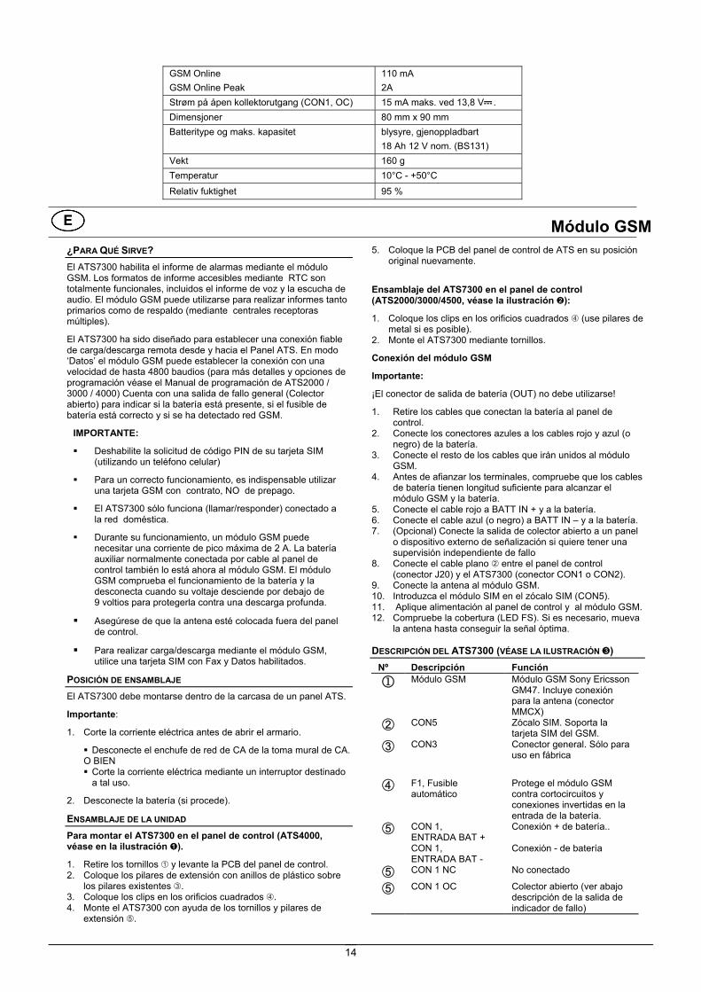
Módulo GSM ¿PARA QUÉ SIRVE? El ATS7300 habilita el informe de alarmas mediante el módulo GSM. Los formatos de informe accesibles mediante RTC son totalmente funcionales, incluidos el informe de voz y la escucha de audio. El módulo GSM puede utilizarse para realizar informes tanto primarios como de respaldo (mediante centrales receptoras múltiples).
El ATS7300 ha sido diseñado para establecer una conexión fiable de carga/descarga remota desde y hacia el Panel ATS. En modo ‘Datos’ el módulo GSM puede establecer la conexión con una velocidad de hasta 4800 baudios (para más detalles y opciones de programación véase el Manual de programación de ATS2000 / 3000 / 4000) Cuenta con una salida de fallo general (Colector abierto) para indicar si la batería está presente, si el fusible de batería está correcto y si se ha detectado red GSM.
IMPORTANTE:
Deshabilite la solicitud de código PIN de su tarjeta SIM (utilizando un teléfono celular)
Para un correcto funcionamiento, es indispensable utilizar una tarjeta GSM con contrato, NO de prepago.
El ATS7300 sólo funciona (llamar/responder) conectado a la red doméstica.
Durante su funcionamiento, un módulo GSM puede necesitar una corriente de pico máxima de 2 A. La batería auxiliar normalmente conectada por cable al panel de control también lo está ahora al módulo GSM. El módulo GSM comprueba el funcionamiento de la batería y la desconecta cuando su voltaje desciende por debajo de 9 voltios para protegerla contra una descarga profunda.
Asegúrese de que la antena esté colocada fuera del panel de control.
Para realizar carga/descarga mediante el módulo GSM, utilice una tarjeta SIM con Fax y Datos habilitados.
POSICIÓN DE ENSAMBLAJE El ATS7300 debe montarse dentro de la carcasa de un panel ATS.
Importante:
1. Corte la corriente eléctrica antes de abrir el armario.
Desconecte el enchufe de red de CA de la toma mural de CA. O BIEN Corte la corriente eléctrica mediante un interruptor destinado a tal uso.
2. Desconecte la batería (si procede).
ENSAMBLAJE DE LA UNIDAD Para montar el ATS7300 en el panel de control (ATS4000, véase en la ilustración ).
1. Retire los tornillos y levante la PCB del panel de control. 2. Coloque los pilares de extensión con anillos de plástico sobre
los pilares existentes . 3. Coloque los clips en los orificios cuadrados . 4. Monte el ATS7300 con ayuda de los tornillos y pilares de
extensión .
5. Coloque la PCB del panel de control de ATS en su posición original nuevamente.
Ensamblaje del ATS7300 en el panel de control (ATS2000/3000/4500, véase la ilustración ):
1. Coloque los clips en los orificios cuadrados (use pilares de metal si es posible).
2. Monte el ATS7300 mediante tornillos. Conexión del módulo GSM
Importante:
¡El conector de salida de batería (OUT) no debe utilizarse!
1. Retire los cables que conectan la batería al panel de control.
2. Conecte los conectores azules a los cables rojo y azul (o negro) de la batería.
3. Conecte el resto de los cables que irán unidos al módulo GSM.
4. Antes de afianzar los terminales, compruebe que los cables de batería tienen longitud suficiente para alcanzar el módulo GSM y la batería.
5. Conecte el cable rojo a BATT IN + y a la batería. 6. Conecte el cable azul (o negro) a BATT IN – y a la batería. 7. (Opcional) Conecte la salida de colector abierto a un panel
o dispositivo externo de señalización si quiere tener una supervisión independiente de fallo
8. Conecte el cable plano entre el panel de control (conector J20) y el ATS7300 (conector CON1 o CON2).
9. Conecte la antena al módulo GSM. 10. Introduzca el módulo SIM en el zócalo SIM (CON5). 11. Aplique alimentación al panel de control y al módulo GSM. 12. Compruebe la cobertura (LED FS). Si es necesario, mueva
la antena hasta conseguir la señal óptima. DESCRIPCIÓN DEL ATS7300 (VÉASE LA ILUSTRACIÓN )
Nº Descripción Función
1 Módulo GSM Módulo GSM Sony Ericsson GM47. Incluye conexión para la antena (conector MMCX)
CON5 Zócalo SIM. Soporta la tarjeta SIM del GSM.
CON3 Conector general. Sólo para uso en fábrica
F1, Fusible automático
Protege el módulo GSM contra cortocircuitos y conexiones invertidas en la entrada de la batería.
CON 1, ENTRADA BAT +
Conexión + de batería..
CON 1, ENTRADA BAT -
Conexión - de batería
CON 1 NC No conectado
CON 1 OC Colector abierto (ver abajo descripción de la salida de indicador de fallo)

15
Nº Descripción Función CON 2/CON 4
(Conector del sistema)
Comunica al ATS7300 con el panel principal.
LED Estado de los LED.
SALIDA DE INDICADOR DE FALLO (REF. A EN FIG. ) OC (Open collector – Colector Abierto) El colector abierto está controlado por el estado del fusible de batería (F1), presencia de la batería y presencia de la red GSM.
La salida de colector abierto se encuentra en nivél bajo (activa) si la batería está presente, el fusible de batería está correcto y se ha detectado red GSM.
Este estado bajo puede suministrar corriente y es comparado con +12v. En caso de cualquier condición de error esta salida estará a nivel alto.
IMPORTANTE:
Después de la puesta en marcha la salida de colector abierto permanecerá a nivel alto hasta que se haya detectado la conexión con la red (entre 5 y 10 segundos)
La salida de colector abierto tiene la misma funcionalidad que el fallo de línea, el cual es transmitido al panel, excepto que la salida de colector abierto no es retardada. El fallo de línea es transmitido al panel con un retardo de 1 minuto
LED MI
El LED MI (verde) indica el estado de la interface de comunicación con el panel.
Tabla 1. Estado del LED MI
LED Descripción Ciclo de trabajo
Velocidad (+/- 10%)
100% - Encendido (ON) (si ninguno de los casos siguientes es válido)
0% - Sin alimentación o error de alimentación
25% 1 seg Iniciación correcta, estableciendo comunicación
50% 1 seg Funcionamiento correcto, comunicación establecida
75% 500 ms Error de hardware 50% 250 ms Error de comunicación, esperando
LED Descripción Ciclo de trabajo
Velocidad (+/- 10%)
a que se reinicie CS
El LED CS (Rojo) indica el estado de los datos de audio transmitidos a la central receptora.
Tabla 2. Estado del LED CS
LED Descripción Ciclo de trabajo
Velocidad (+/- 10%)
100% - Conectado 0% - Desconectado
10% 1 seg Conectando 50% 1 seg Emite una señal sonora
FS
El LED (verde) FS indica la cobertura o la intensidad de la señal detectada por el módulo GSM. El número de parpadeos indica el nivel. Se marca una pausa de 1 segundo entre 2 grupos de parpadeos.
Tabla 3.Estado del LED FS
LED Descripción Desconectado No hay cobertura (no se ha
detectado ninguna red) Parpadea (1 – 5) Indicación de la cobertura, de baja
(1) a óptima (5) Conectado Encendido, pero no conectado a una
red GSM
El LED GSM (verde) indica el estado del módulo GSM.
Tabla 4. Estado del LED GSM
LED Descripción Desconectado No hay alimentación o el módulo
está apagado (estado OFF). Parpadea Encendido y conectado a una red Conectado Encendido, pero no conectado a una
red El módulo GSM indica un fallo de línea al panel de control si no detecta la red doméstica en 1 minu
Especificaciones técnicas
Fuente de alimentación Mediante cable plano conectado al panel de control Mediante CON1, BAT conectado a la batería auxiliar
10 – 15 V
10 – 15 V
Consumo eléctrico (a 13,8 V ± 5%) Bus MI GSM desconectado GSM en línea GSM pico en línea
20 mA 15 mA 110 mA 2A
Corriente de salida de colector abierto (CON1, OC) 15 mA máx. a 13,8 V Dimensiones 80 mm x 90 mm Tipo de batería y capacidad máxima Acumulador de plomo – ácido.
18 Ah 12 V nom. (BS131) Peso 160 gr. Temperatura de 10°C a +50°C Humedad relativa 95 %

16
GSM Modul HVAD GØR DEN? ATS7300 gør det muligt at foretage en alarmtransmission via GSM. Alle de transmissionsformater, der står til rådighed gennem PSTN er fuldt funktionsdygtige, herunder også tale-transmission eller audio lytte ind. GSM modulet kan bruges til primær transmission såvel som til backup transmission (ved brug af flere kontrolcentraler).
ATS7300 giver mulighed for at oprette en stabil GSM-forbindelse for up/download fra mellem et ATS system og en PC med Titan. Når GSM-modulet er i data mode kan overførsel ske med op til 4800 baud (for yderligere detaljer og programmering henvises til ATS2000 / 3000 / 4000 programmeringsmanual. En generel fejl udgang (OC) viser at akkumulator er tilsluttet, akk. Sikring er ok og GSM-nettet er tilstede
VIGTIGT:
Pin koden skal frokobles på Sim kortet (gøres via en mobiltelefon)
Et GSM SIM-kort med abonnement er nødvendigt (Skal købes direkte ved en teleudbyder), for at GSM-modulet kan fungere.
ATS7300 vil kun fungere (opkald/svar), når den er tilsluttet det lokale netværk.
Et GSM modul kan have et strømforbrug helt op til 2 A ved spidsbelastning. Nødstrømsakkumulatoren, som normalt er tilsluttet centralenheden, skal derfor også være tilsluttet til GSM modulet. GSM modulet kontrollerer akkumulatorens aktielle spænding og frakobler akkumulatoren, når spændingen bliver lavere end 9 volt. Dette vil beskytte akkumulatoren mod dybdeafladning.
Sørg for, at GSM modulets antenne er placeret uden for centralenhedens metalkabinet.
For at kunne op/downloade via GSM modulet, skal der benyttes SIM kort der tilllader fax og data.
MONTERINGSSTED ATS7300 skal monteres inde i et ATS kabinet.
Vigtigt:
1. Afbryd netspændingen før kabinettet åbnes.
2. Afbryd forbindelsen til akkumulatoren.
MONTERING AF ENHEDEN Montering af ATS7300 i centralenheden (ATS4000, jf. figur ).
1. Fjern skruerne og løft centralenhedens PCB af. 2. Placer forlængerstagene med plastikringene oven på de
eksisterende stag . 3. Placer metalclipsene i de firkantede huller . 4. Monter ATS7300 ved hjælp af skruerne og forlængerstag
. 5. Placer på ny ATS centralenhedens PCB i dens oprindelige
position.
Montering af ATS7300 i centralenheden (ATS2000/3000/4500, jf. figur )
1. Placer metalclipsene i de firkantede huller (brug om muligt metalstag).
2. Monter ATS7300 ved hjælp af skruerne. Tilslutning af GSM modul
Fjern sikringen fra AC tilslutning.
1. Fjern akkumulatorledningerne, der går fra centralprint til akkumulatoren.
2. Monter den blå connektor til den røde og blå (eller sorte) akkulumator ledning
3. Tilslut øvrige forbindelser til GSM modulet.
4. Før tilslutning skal det sikres at akkumulator ledningerne kan nå fra GMS modulet til Akkumulatoren.
5. Tilslut den røde ledning til BATT IN + og akkumulatoren 6. Tilslut den blå (eller sorte) ledning til BATT IN – og
akkumulatoren. 7. (Valgfrit) Forbind open collector udgangen til en ekstern
signalgiver eller til centralen for at opnå en ekstra fejl-overvågning
8. Tilslut fladkabelet mellem centralenheden (konnektor J20) og ATS7300 (konnektor CON1 eller CON2).
9. Tilslut antennen til GSM modulet. 10. Indsæt SIM-kortet i SIM-soklen (CON5). 11. Tilslut spænding til centralenheden og GSM modulet. 12. Kontroller feltstyrken (FS LED). Flyt om nødvendigt
antennen for at opnå et bedre signal. BESKRIVELSE AF ATS7300 (JF. FIGUR )
Nr. Beskrivelse Funktion
1 GSM modul Sony Ericsson GM47 GSM modul. Indkluderer antenne-tilslutning (MMCX konnektor)
CON5 SIM-sokkel. Til SIM-kort.
CON3 Udgangskonnektor. Kun for fabriksbrug.
F1, Automat sikring Sikring F1 beskytter GSM modulet mod kortslutning / fejl polaritet ved tilslutning af akkumulator.
CON 1, BATT IN + Akk. + forbindelse .
CON 1, BATT IN - Akk - forbindelse.
CON 1 NC Ikke tilsluttet
CON 1 OC Open collector (se udgang for fejlindikeringfrjl-indikering
CON 2/CON 4 (Systemkonnektor)
Kommunikerer mellem ATS7300 og ATS centralen.
LEDs Statusindikering (se Tabel 1)
UDGANG FOR FEJL (REF. TIL I FIG. ) OC (Open collector) Open collector udgangen er styret af akk. sikring (F1), akk. tilsluttet og at GSM-nettet er tilstede.
Open collector udgangen er lav (aktiv -), hvis akkumulator er tilsluttet, akk. sikringen er ok og GSM net er ok.
Ved fejl på en af de 3 nævnte muligheder vil udgangen skifte til høj (+12 v).
VIGTIGT:
Efter power up, vil open collector udgangen forblive høj indtil det tilsluttede GSM netværk er detekteret (typisk 5 til 10 sekunder).
Open collector udgangen har samme fuktion som liniefejl og bliver rapporteret til centralen, dog har open collector udgangen ingen forsinkelse.
Rapportering af linefejl til central er forsinket 1 minnut. LEDS MI
MI LED (grøn) angiver status for kommunikationsinterface til centralen.
Tabel 1. MI LED status
LED Beskrivelse Aktivitets-
periode Varighed (+/- 10%)
100% - Power ON – Spænding tilsluttet (i det tilfælde at ingen af nedenstående er gældende)
0% - Ingen spænding / spændingsfejl 25% 1 sek. Initialisering OK, afventer
17
LED Beskrivelse Aktivitets-
periode Varighed (+/- 10%)
kommunikation 50% 1 sek. Alt OK, kommunikation i gang 75% 500 ms Hardwarefejl 50% 250 ms Kommunikationsfejl, afventer
geninitialisering. CS
CS LED (Rød) angiver status for transmission til kontrolcentral Tabel 2. CS LED status
LED Beskrivelse Aktivitets-
periode Varighed (+/- 10%)
100% - Tilsluttet 0% - Offline
10% 1 sek. Tilslutning sker 50% 1 sek. Ringning sker
FS
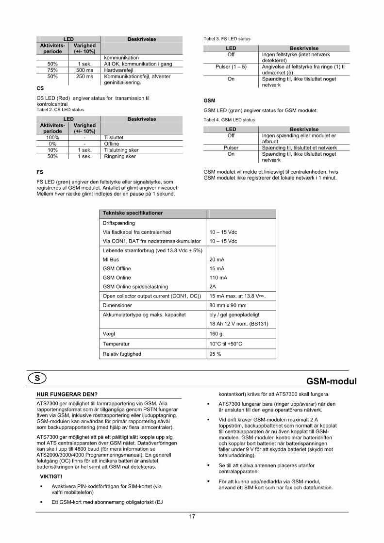
FS LED (grøn) angiver den feltstyrke eller signalstyrke, som registreres af GSM modulet. Antallet af glimt angiver niveauet. Mellem hver række glimt indføjes der en pause på 1 sekund.
Tabel 3. FS LED status
LED Beskrivelse Off Ingen feltstyrke (intet netværk
detekteret) Pulser (1 – 5) Angivelse af feltstyrke fra ringe (1) til
udmærket (5) On Spænding til, ikke tilsluttet noget
netværk
GSM
GSM LED (grøn) angiver status for GSM modulet.
Tabel 4. GSM LED status
LED Beskrivelse Off Ingen spænding eller modulet er
afbrudt Pulser Spænding til, tilsluttet et netværk
On Spænding til, ikke tilsluttet noget netværk
GSM modulet vil melde et liniesvigt til centralenheden, hvis GSM modulet ikke registrerer det lokale netværk i 1 minut.
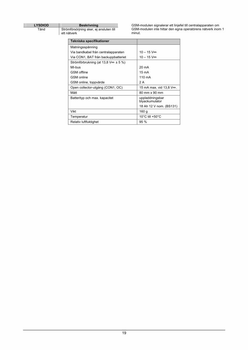
Tekniske specifikationer
Driftspænding
Via fladkabel fra centralenhed
Via CON1, BAT fra nødstrømsakkumulator
10 – 15 Vdc
10 – 15 Vdc
Løbende strømforbrug (ved 13.8 Vdc ± 5%)
MI Bus
GSM Offline
GSM Online
GSM Online spidsbelastning
20 mA
15 mA
110 mA
2A
Open collector output current (CON1, OC)) 15 mA max. at 13.8 V .
Dimensioner 80 mm x 90 mm
Akkumulatortype og maks. kapacitet bly / gel genopladeligt
18 Ah 12 V nom. (BS131)
Vægt 160 g.
Temperatur 10°C til +50°C
Relativ fugtighed 95 %
GSM-modul HUR FUNGERAR DEN? ATS7300 ger möjlighet till larmrapportering via GSM. Alla rapporteringsformat som är tillgängliga genom PSTN fungerar även via GSM, inklusive röstrapportering eller ljudupptagning. GSM-modulen kan användas för primär rapportering såväl som backupprapportering (med hjälp av flera larmcentraler).
ATS7300 ger möjlighet att på ett pålitligt sätt koppla upp sig mot ATS centralapparaten över GSM nätet. Dataöverföringen kan ske i upp till 4800 baud (för mera information se ATS2000/3000/4000 Programmeringsmanual). En generell felutgång (OC) finns för att indikera batteri är anslutet, batterisäkringen är hel samt att GSM nät detekteras.
VIKTIGT!
Avaktivera PIN-kodsförfrågan för SIM-kortet (via valfri mobiltelefon)
Ett GSM-kort med abonnemang obligatoriskt (EJ
kontantkort) krävs för att ATS7300 skall fungera.
ATS7300 fungerar bara (ringer upp/svarar) när den är ansluten till den egna operatörens nätverk.
Vid drift kräver GSM-modulen maximalt 2 A toppström, backuppbatteriet som normalt är kopplat till centralapparaten är nu även kopplat till GSM-modulen. GSM-modulen kontrollerar batteridriften och kopplar bort batteriet när batterispänningen faller under 9 V för att skydda batteriet (skydd mot totalurladdning).
Se till att själva antennen placeras utanför centralapparaten.
För att kunna upp/nedladda via GSM-modul, använd ett SIM-kort som har fax och datafunktion.

18
MONTERINGSPLATS ATS7300 måste monteras i ett ATS-apparathölje.
Viktigt:
1. Koppla bort huvudmatningen innan du öppnar lådan.
Dra ur AC-nätkontakten ur AC-nätuttaget. ELLER Koppla bort huvudmatningen med hjälp av den därför
avsedda brytaren.
2. Koppla bort batteriet (om så är tillämpligt).
MONTERA ENHETEN Montera ATS7300 i centralapparaten (ATS4000,se figur ).
1. Ta bort skruvarna och lyft av centralapparatens PCB. 2. Placera expansionspinnarna med plastringarna på de
befintliga pinnarna . 3. Placera clipsen i de fyrkantiga hålen . 4. Montera ATS7300 med hjälp av skruvarna och
expansionspinnarna . 5. Placera ATS-centralapparatens PCB i sitt originalläge.
Montera ATS7300 i centralapparaten (ATS2000/3000/4500, se figur )
1. Placera clipsen i de fyrkantiga hålen (använd metallpinnar om sådana finns).
2. Montera ATS7300 med hjälp av skruvar. Ansluta GSM-modulen
Koppla ur AC huvudmatningskontakten från vägguttaget.
1. Ta bort batterikablarna som går från batteriet till centralapparaten.
2. Anslut de blå anslutningarna till de röda och blå (eller svarta) batterikablarna.
3. Anslut de resterande kablarna, och fixera med buntband till GSM-modulen.
4. Innan fixering, se till att alla kablar räcker till GSM-modulen och batteriet.
5. Anslut röd kabel till BATT IN + och batteriet. 6. Anslut blå (eller svart) kabel till BATT IN – och batteriet. 7. Anslut OC utgången till centralapparaten för att få fel
övervakning. 8. Anslut den platta kabeln mellan centralapparaten
(kontakt J20) och ATS7300 (kontakt CON1 eller CON2). 9. Anslut antennen till GSM-modulen. 10. Sätt i SIM-modulen i SIM-uttaget (CON5). 11. Slå på strömmen till centralapparaten och GSM-modulen. 12. Kontrollera fältstyrkan (lysdioden FS). Om så krävs flyttar
du antennen för att få bästa möjliga signal. BESKRIVNING AV ATS7300 (SE FIGUR )
Nr. Beskrivning Funktion
1 GSM-modul Sony Ericsson GM47 GSM-modul. Antennanslutning ingår (MMCX-kontakt)
CON5 SIM-uttag. Innehåller GSM SIM-kortet.
CON3 Används ej.
F1, automatsäkring Används för att skydda GSM-modulen mot kortslutningar/omvänd polaritet i batteriingången.
CON 1, BAT IN + Batteri + anslutning.
CON 1, BAT IN - Batteri - anslutning CON 1 NC Används ej.
CON1 OC ÖC utgång. Se felindikerings utgång
CON 2/CON 4 (Systemanslutning)
Kommunication mellan ATS7300 och centralapparaten.
Lysdioder Lysdioder som visar status.
FELINDIKERINGS UTGÅNG (SE FIGUR) OC utgång övervakar batterisäkringen (F1) samt närvaro av batteri och GSM nät. OC utgången är låg (aktiv) när batteri är anslutet, batterisäkringen är hel samt GSM nät detekterat. VIKTIGT: Efter uppstart är OC utgången hög i ca 5 – 10 sekunder tills en korrekt GSM signal kan detekteras. OC utgången har samma funktionalitet som linjefel vilket rapporteras till centralapparaten via flatkabeln. OC utgången är inte fördröjd. Linjefel via flatkabeln är fördröjd med 1 minut.
LYSDIODER MI
Lysdioden MI (grön) visar status för kommunikationsgränssnittet till centralapparaten.
Tabell 1. MI-lysdiodstatus
LYSDIOD Beskrivning Puls Längd
(+/- 10 %)
100 % - Ström PÅ (i de fall ingen av nedanstående fall gäller)
0 % - Ingen ström eller strömavbrott 25 % 1 sek Initiering OK, väntar på
kommunikation 50 % 1 sek Allt OK, kommunikation sker 75 % 500 ms Hårdvarufel 50 % 250 ms Kommunikationsfel, väntar på
återinitiering.
CS
CS-lysdioden(röd) visar status för den ljudinformation som sänds till larmcentralen
Tabell 2. CS-lysdiodstatus
LYSDIOD Beskrivning Puls Längd
(+/- 10 %)
100 % - Ansluten 0 % - Offline
10 % 1 sek Ansluter 50 % 1 sek Ringer
FS
FS-lysdioden(grön) visar den fältstyrka eller signalstyrka som GSM-modulen tar emot. Antalet blinkningar visar nivån. Mellan varje blinkningsomgång görs en paus på 1 sekund.
Tabell 3. FS-lysdiodstatus
LYSDIOD Beskrivning Släckt Ingen fältstyrka (inget nätverk har
upptäckts) Blinkar (1 – 5) Indikation om fältstyrka från dålig (1)
till utmärkt (5) Tänd Strömförsörjning sker, ej ansluten till
ett nätverk
GSM
GSM-lysdioden (grön) visar status för GSM-modulen.
Tabell 4. GSM-lysdiodstatus
LYSDIOD Beskrivning Släckt Ingen strömförsörjning eller
avstängd modul Blinkar Strömförsörjning sker, ansluten till
ett nätverk
19
LYSDIOD Beskrivning Tänd Strömförsörjning sker, ej ansluten till
ett nätverk
GSM-modulen signalerar ett linjefel till centralapparaten om GSM-modulen inte hittar den egna operatörens nätverk inom 1 minut.
Tekniska specifikationer Matningsspänning Via bandkabel från centralapparaten Via CON1, BAT från backuppbatteriet
10 – 15 V 10 – 15 V
Strömförbrukning (at 13,8 V ± 5 %) MI-bus GSM offline GSM online GSM online, toppvärde
20 mA 15 mA 110 mA 2 A
Open collector-utgång (CON1, OC) 15 mA max. vid 13,8 V . Mått 80 mm x 90 mm Batterityp och max. kapacitet uppladdningsbar
blyackumulator 18 Ah 12 V nom. (BS131)
Vikt 160 g Temperatur 10°C till +50°C Relativ luftfuktighet 95 %
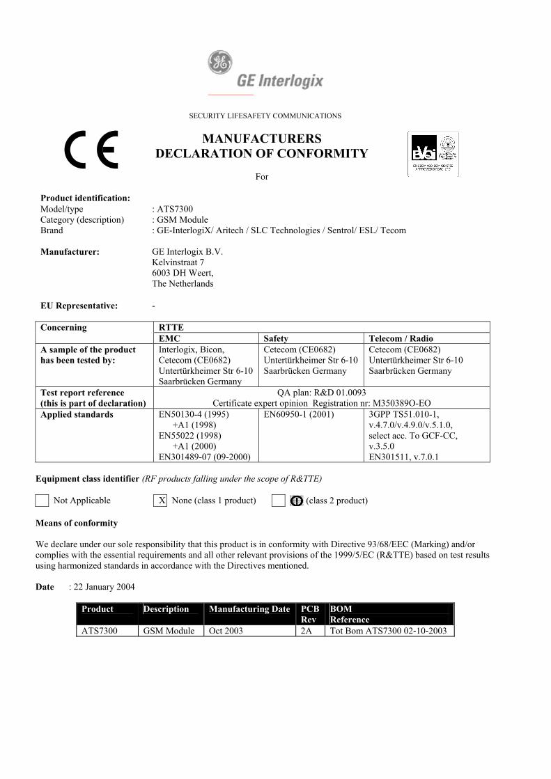
SECURITY LIFESAFETY COMMUNICATIONS
MANUFACTURERS DECLARATION OF CONFORMITY
For
Product identification: Model/type : ATS7300 Category (description) : GSM Module Brand : GE-InterlogiX/ Aritech / SLC Technologies / Sentrol/ ESL/ Tecom
Manufacturer: GE Interlogix B.V.
Kelvinstraat 7 6003 DH Weert, The Netherlands
EU Representative: -
Concerning RTTE EMC Safety Telecom / Radio A sample of the product has been tested by:
Interlogix, Bicon, Cetecom (CE0682) Untertürkheimer Str 6-10 Saarbrücken Germany
Cetecom (CE0682) Untertürkheimer Str 6-10 Saarbrücken Germany
Cetecom (CE0682) Untertürkheimer Str 6-10 Saarbrücken Germany
Test report reference (this is part of declaration)
QA plan: R&D 01.0093 Certificate expert opinion Registration nr: M350389O-EO
Applied standards EN50130-4 (1995) +A1 (1998) EN55022 (1998) +A1 (2000) EN301489-07 (09-2000)
EN60950-1 (2001) 3GPP TS51.010-1, v.4.7.0/v.4.9.0/v.5.1.0, select acc. To GCF-CC, v.3.5.0 EN301511, v.7.0.1
Equipment class identifier (RF products falling under the scope of R&TTE)
Not Applicable X None (class 1 product) (class 2 product) Means of conformity We declare under our sole responsibility that this product is in conformity with Directive 93/68/EEC (Marking) and/or complies with the essential requirements and all other relevant provisions of the 1999/5/EC (R&TTE) based on test results using harmonized standards in accordance with the Directives mentioned. Date : 22 January 2004
Product Description Manufacturing Date PCBRev
BOM Reference
ATS7300 GSM Module Oct 2003 2A Tot Bom ATS7300 02-10-2003


![SM5100B-D GSM/GPRS Module Hardware Specification · SM5100B-D GSM/GPRS Module Hardware Specification 2 Product concept . SM5100B-D is a Dual-Band EGSM900/DCS1800[*2] GSM/GPRS module](https://static.fdocuments.net/doc/165x107/5e2e01faf5dc2f700f118a9d/sm5100b-d-gsmgprs-module-hardware-specification-sm5100b-d-gsmgprs-module-hardware.jpg)