Atmospheric Electric Field Mill Deployment in Southeastern of Brazil · Ethernet local area network...
11
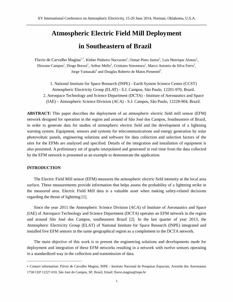
XV International Conference on Atmospheric Electricity, 15-20 June 2014, Norman, Oklahoma, U.S.A. 1 Atmospheric Electric Field Mill Deployment in Southeastern of Brazil Flavio de Carvalho Magina 1,* , Kleber Pinheiro Naccarato 1 , Osmar Pinto Junior 1 , Luis Henrique Alonso 1 , Diovane Campos 1 , Diogo Borsoi 1 , Arthur Mello 1 , Cristiano Simomura 1 , Marco Antonio da Silva Ferro 2 , Jorge Yamasaki 2 and Douglas Roberto de Matos Pimentel 2 . 1. National Institute for Space Research (INPE) - Earth System Science Center (CCST) Atmospheric Electricity Group (ELAT) - S.J. Campos, São Paulo, 12201-970, Brazil. 2. Aerospace Technology and Science Department (DCTA) - Institute of Aeronautics and Space (IAE) – Atmospheric Science Division (ACA) - S.J. Campos, São Paulo, 12228-904, Brazil. ABSTRACT: This paper describes the deployment of an atmospheric electric field mill sensor (EFM) network designed for operation in the region and around of São José dos Campos, Southeastern of Brazil, in order to generate data for studies of atmospheric electric field and the development of a lightning warning system. Equipment, sensors and systems for telecommunications and energy generation by solar photovoltaic panels, engineering solutions and software for data collection and selection factors of the sites for the EFMs are analyzed and specified. Details of the integration and installation of equipment is also presented. A preliminary set of graphs interpolated and generated in real time from the data collected by the EFM network is presented as an example to demonstrate the application. INTRODUCTION The Electric Field Mill sensor (EFM) measures the atmospheric electric field intensity at the local area surface. These measurements provide information that helps assess the probability of a lightning strike in the measured area. Electric Field Mill data is a valuable asset when making safety-related decisions regarding the threat of lightning [1]. Since the year 2011 the Atmospheric Science Division (ACA) of Institute of Aeronautics and Space (IAE) of Aerospace Technology and Science Department (DCTA) operates an EFM network in the region and around São José dos Campos, southeastern Brazil [2]. In the last quarter of year 2013, the Atmospheric Electricity Group (ELAT) of National Institute for Space Research (INPE) integrated and installed five EFM sensors in the same geographical region as a complement to the DCTA network. The main objective of this work is to present the engineering solutions and developments made for deployment and integration of these EFM networks resulting in a network with twelve sensors operating in a standardized way in the collection and transmission of data. Contact information: Flávio de Carvalho Magina, INPE - Instituto Nacional de Pesquisas Espaciais, Avenida dos Astronautas 1758 CEP 12227-010, São José do Campos, SP, Brazil, Email: [email protected]
-
Upload
truongtruc -
Category
Documents
-
view
213 -
download
0
Transcript of Atmospheric Electric Field Mill Deployment in Southeastern of Brazil · Ethernet local area network...
XV International Conference on Atmospheric Electricity, 15-20 June 2014, Norman, Oklahoma, U.S.A.
1
Atmospheric Electric Field Mill Deployment
in Southeastern of Brazil
Flavio de Carvalho Magina1,*, Kleber Pinheiro Naccarato1, Osmar Pinto Junior1, Luis Henrique Alonso1, Diovane Campos1, Diogo Borsoi1, Arthur Mello1, Cristiano Simomura1, Marco Antonio da Silva Ferro2,
Jorge Yamasaki2 and Douglas Roberto de Matos Pimentel2.
1. National Institute for Space Research (INPE) - Earth System Science Center (CCST) Atmospheric Electricity Group (ELAT) - S.J. Campos, São Paulo, 12201-970, Brazil.
2. Aerospace Technology and Science Department (DCTA) - Institute of Aeronautics and Space (IAE) – Atmospheric Science Division (ACA) - S.J. Campos, São Paulo, 12228-904, Brazil.
ABSTRACT: This paper describes the deployment of an atmospheric electric field mill sensor (EFM) network designed for operation in the region and around of São José dos Campos, Southeastern of Brazil, in order to generate data for studies of atmospheric electric field and the development of a lightning warning system. Equipment, sensors and systems for telecommunications and energy generation by solar photovoltaic panels, engineering solutions and software for data collection and selection factors of the sites for the EFMs are analyzed and specified. Details of the integration and installation of equipment is also presented. A preliminary set of graphs interpolated and generated in real time from the data collected by the EFM network is presented as an example to demonstrate the application.
INTRODUCTION
The Electric Field Mill sensor (EFM) measures the atmospheric electric field intensity at the local area surface. These measurements provide information that helps assess the probability of a lightning strike in the measured area. Electric Field Mill data is a valuable asset when making safety-related decisions regarding the threat of lightning [1].
Since the year 2011 the Atmospheric Science Division (ACA) of Institute of Aeronautics and Space (IAE) of Aerospace Technology and Science Department (DCTA) operates an EFM network in the region and around São José dos Campos, southeastern Brazil [2]. In the last quarter of year 2013, the Atmospheric Electricity Group (ELAT) of National Institute for Space Research (INPE) integrated and installed five EFM sensors in the same geographical region as a complement to the DCTA network.
The main objective of this work is to present the engineering solutions and developments made for deployment and integration of these EFM networks resulting in a network with twelve sensors operating in a standardized way in the collection and transmission of data.
Contact information: Flávio de Carvalho Magina, INPE - Instituto Nacional de Pesquisas Espaciais, Avenida dos Astronautas
1758 CEP 12227-010, São José do Campos, SP, Brazil, Email: [email protected]
XV International Conference on Atmospheric Electricity, 15-20 June 2014, Norman, Oklahoma, U.S.A.
2
LOCATION OF THE EFM SENSORS
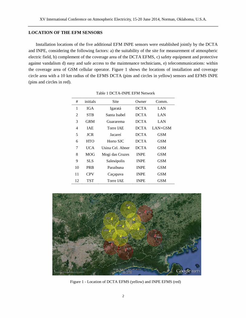
Installation locations of the five additional EFM INPE sensors were established jointly by the DCTA and INPE, considering the following factors: a) the suitability of the site for measurement of atmospheric electric field, b) complement of the coverage area of the DCTA EFMS, c) safety equipment and protective against vandalism d) easy and safe access to the maintenance technicians, e) telecommunications: within the coverage area of GSM cellular operator. Figure 1 shows the locations of installation and coverage circle area with a 10 km radius of the EFMS DCTA (pins and circles in yellow) sensors and EFMS INPE (pins and circles in red).
Table 1 DCTA-INPE EFM Network
Figure 1 - Location of DCTA EFMS (yellow) and INPE EFMS (red)
# initials Site Owner Comm.
1 IGA Igaratá DCTA LAN 2 STB Santa Isabel DCTA LAN
3 GRM Guararema DCTA LAN 4 IAE Torre IAE DCTA LAN+GSM 5 JCR Jacareí DCTA GSM 6 HTO Horto SJC DCTA GSM
7 UCA Usina Cel. Abner DCTA GSM 8 MOG Mogi das Cruzes INPE GSM 9 SLS Salesópolis INPE GSM
10 PRB Paraibuna INPE GSM
11 CPV Caçapava INPE GSM 12 TST Torre IAE INPE GSM

XV International Conference on Atmospheric Electricity, 15-20 June 2014, Norman, Oklahoma, U.S.A.
3
The EFM TST of INPE network (EFM number 12 in the Table 1) is used to compare measurements with EFM IAE of DCTA network (EFM number 4 in the Table 1). Both sensors are installed in the same site, a few meters away from each other. For this reason, in the map of Figure 1 is only represented the EFM IAE of DCTA network.
EQUIPMENT
The DCTA EFM network is composed of seven EFM sensors manufactured by Campbell Scientific Inc., model CS110 (Figure 2). This sensor comes standard with an integrated datalogger (CR1000) which is mounted in the same housing of the sensor. Instead of the traditional rotating vane of a traditional field mill, the CS110 uses a reciprocating shutter electrically connected to ground potential by a flexible stainless-steel strap. According to Campbell Scientific [3], the reciprocating approach provides better low frequency error performance than the traditional rotating vane field mill because it has a convenient zero-field (closed shutter) reference. The CS110 is powered by battery 12 V / 24 Ah rechargeable by solar panels of 30 W.
Figure 2 – Campbell Scientific CS110 EFM [3] Figure 3 – Vaisala EFM550 sensor head [1]
The INPE EFM network consists of five Vaisala EFM550 [1] sensors that include a rotating plate (the
rotor) and a fixed set of plates (the stator). The motor and electronics of the EFM550 are also housed in the case (Figure 3). As the rotor turns, it alternately exposes and shields the stator to and from the electric field. Detectable charges are induced onto the stator plates as the rotor chops the electric field. This charge is sampled at the instant that the rotor provides maximum stator plate exposure giving a series of samples whose magnitude and polarity are proportional to the electrical field intensity. This output voltage is processed by the Data Collection and Processing Module (Figure 4) that has a 1200 baud streaming digital output on an RS-232 communications port for transmission to a computer for display or alarm signaling in a traditional EFM550 system installation.
XV International Conference on Atmospheric Electricity, 15-20 June 2014, Norman, Oklahoma, U.S.A.
4
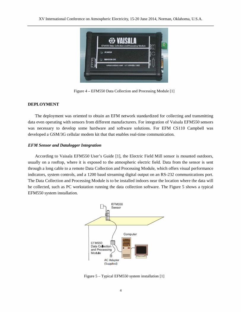
Figure 4 – EFM550 Data Collection and Processing Module [1]
DEPLOYMENT
The deployment was oriented to obtain an EFM network standardized for collecting and transmitting data even operating with sensors from different manufacturers. For integration of Vaisala EFM550 sensors was necessary to develop some hardware and software solutions. For EFM CS110 Campbell was developed a GSM/3G cellular modem kit that that enables real-time communication.
EFM Sensor and Datalogger Integration
According to Vaisala EFM550 User’s Guide [1], the Electric Field Mill sensor is mounted outdoors, usually on a rooftop, where it is exposed to the atmospheric electric field. Data from the sensor is sent through a long cable to a remote Data Collection and Processing Module, which offers visual performance indicators, system controls, and a 1200 baud streaming digital output on an RS-232 communications port. The Data Collection and Processing Module is to be installed indoors near the location where the data will be collected, such as PC workstation running the data collection software. The Figure 5 shows a typical EFM550 system installation.
Figure 5 – Typical EFM550 system installation [1]
XV International Conference on Atmospheric Electricity, 15-20 June 2014, Norman, Oklahoma, U.S.A.
5
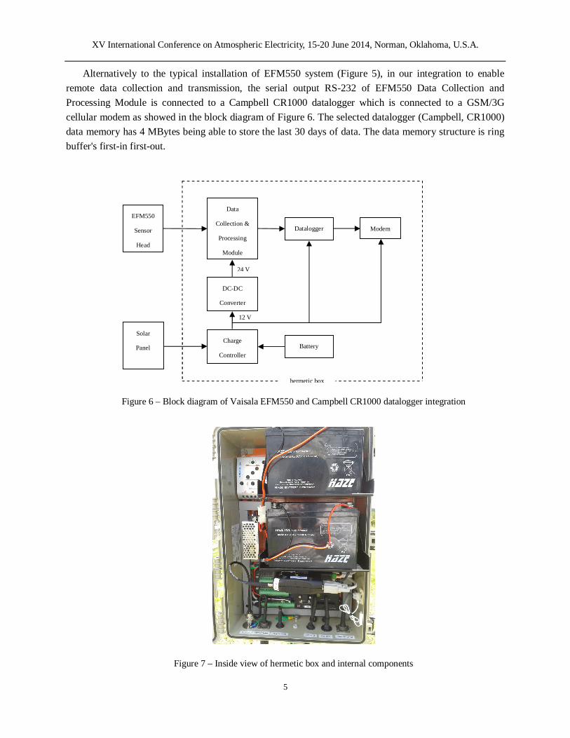
Alternatively to the typical installation of EFM550 system (Figure 5), in our integration to enable remote data collection and transmission, the serial output RS-232 of EFM550 Data Collection and Processing Module is connected to a Campbell CR1000 datalogger which is connected to a GSM/3G cellular modem as showed in the block diagram of Figure 6. The selected datalogger (Campbell, CR1000) data memory has 4 MBytes being able to store the last 30 days of data. The data memory structure is ring buffer's first-in first-out.
Figure 6 – Block diagram of Vaisala EFM550 and Campbell CR1000 datalogger integration
Figure 7 – Inside view of hermetic box and internal components
EFM550
Sensor
Head
Data
Collection &
Processing
Module
Datalogger Modem
DC-DC
Converter
Battery Charge
Controller
hermetic box
24 V
12 V
Solar
Panel
XV International Conference on Atmospheric Electricity, 15-20 June 2014, Norman, Oklahoma, U.S.A.
6
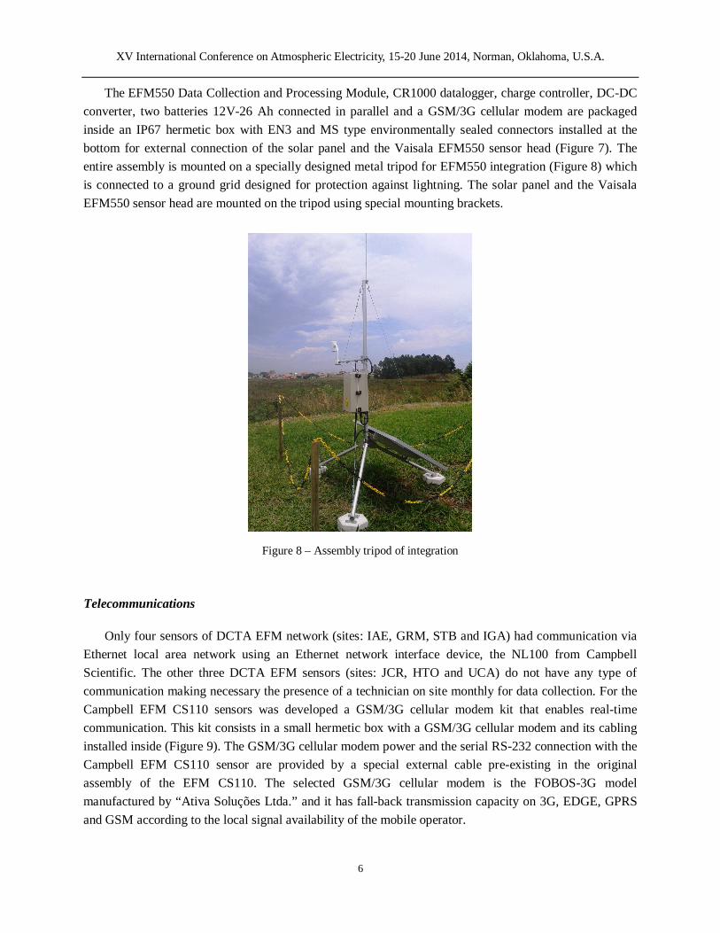
The EFM550 Data Collection and Processing Module, CR1000 datalogger, charge controller, DC-DC converter, two batteries 12V-26 Ah connected in parallel and a GSM/3G cellular modem are packaged inside an IP67 hermetic box with EN3 and MS type environmentally sealed connectors installed at the bottom for external connection of the solar panel and the Vaisala EFM550 sensor head (Figure 7). The entire assembly is mounted on a specially designed metal tripod for EFM550 integration (Figure 8) which is connected to a ground grid designed for protection against lightning. The solar panel and the Vaisala EFM550 sensor head are mounted on the tripod using special mounting brackets.
Figure 8 – Assembly tripod of integration
Telecommunications
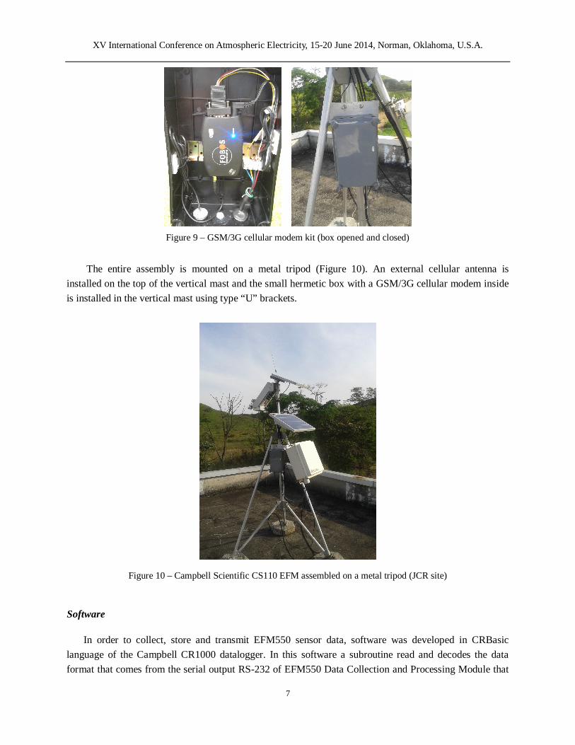
Only four sensors of DCTA EFM network (sites: IAE, GRM, STB and IGA) had communication via Ethernet local area network using an Ethernet network interface device, the NL100 from Campbell Scientific. The other three DCTA EFM sensors (sites: JCR, HTO and UCA) do not have any type of communication making necessary the presence of a technician on site monthly for data collection. For the Campbell EFM CS110 sensors was developed a GSM/3G cellular modem kit that enables real-time communication. This kit consists in a small hermetic box with a GSM/3G cellular modem and its cabling installed inside (Figure 9). The GSM/3G cellular modem power and the serial RS-232 connection with the Campbell EFM CS110 sensor are provided by a special external cable pre-existing in the original assembly of the EFM CS110. The selected GSM/3G cellular modem is the FOBOS-3G model manufactured by “Ativa Soluções Ltda.” and it has fall-back transmission capacity on 3G, EDGE, GPRS and GSM according to the local signal availability of the mobile operator.
XV International Conference on Atmospheric Electricity, 15-20 June 2014, Norman, Oklahoma, U.S.A.
7
Figure 9 – GSM/3G cellular modem kit (box opened and closed)
The entire assembly is mounted on a metal tripod (Figure 10). An external cellular antenna is installed on the top of the vertical mast and the small hermetic box with a GSM/3G cellular modem inside is installed in the vertical mast using type “U” brackets.
Figure 10 – Campbell Scientific CS110 EFM assembled on a metal tripod (JCR site)
Software
In order to collect, store and transmit EFM550 sensor data, software was developed in CRBasic language of the Campbell CR1000 datalogger. In this software a subroutine read and decodes the data format that comes from the serial output RS-232 of EFM550 Data Collection and Processing Module that
XV International Conference on Atmospheric Electricity, 15-20 June 2014, Norman, Oklahoma, U.S.A.
8
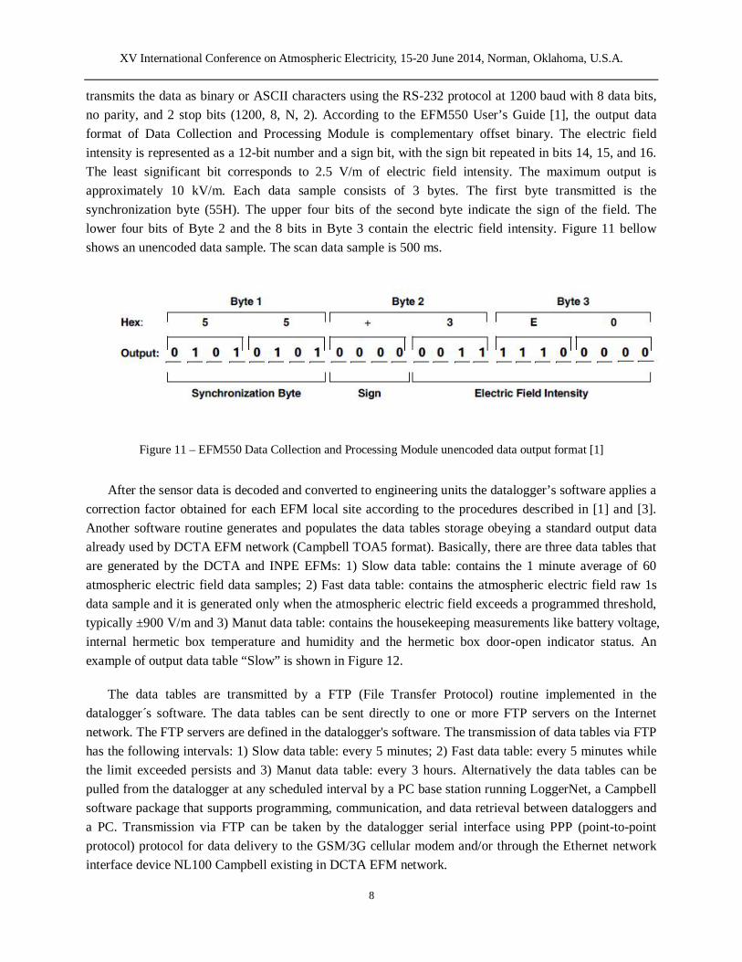
transmits the data as binary or ASCII characters using the RS-232 protocol at 1200 baud with 8 data bits, no parity, and 2 stop bits (1200, 8, N, 2). According to the EFM550 User’s Guide [1], the output data format of Data Collection and Processing Module is complementary offset binary. The electric field intensity is represented as a 12-bit number and a sign bit, with the sign bit repeated in bits 14, 15, and 16. The least significant bit corresponds to 2.5 V/m of electric field intensity. The maximum output is approximately 10 kV/m. Each data sample consists of 3 bytes. The first byte transmitted is the synchronization byte (55H). The upper four bits of the second byte indicate the sign of the field. The lower four bits of Byte 2 and the 8 bits in Byte 3 contain the electric field intensity. Figure 11 bellow shows an unencoded data sample. The scan data sample is 500 ms.
Figure 11 – EFM550 Data Collection and Processing Module unencoded data output format [1]
After the sensor data is decoded and converted to engineering units the datalogger’s software applies a
correction factor obtained for each EFM local site according to the procedures described in [1] and [3]. Another software routine generates and populates the data tables storage obeying a standard output data already used by DCTA EFM network (Campbell TOA5 format). Basically, there are three data tables that are generated by the DCTA and INPE EFMs: 1) Slow data table: contains the 1 minute average of 60 atmospheric electric field data samples; 2) Fast data table: contains the atmospheric electric field raw 1s data sample and it is generated only when the atmospheric electric field exceeds a programmed threshold, typically ±900 V/m and 3) Manut data table: contains the housekeeping measurements like battery voltage, internal hermetic box temperature and humidity and the hermetic box door-open indicator status. An example of output data table “Slow” is shown in Figure 12.
The data tables are transmitted by a FTP (File Transfer Protocol) routine implemented in the datalogger´s software. The data tables can be sent directly to one or more FTP servers on the Internet network. The FTP servers are defined in the datalogger's software. The transmission of data tables via FTP has the following intervals: 1) Slow data table: every 5 minutes; 2) Fast data table: every 5 minutes while the limit exceeded persists and 3) Manut data table: every 3 hours. Alternatively the data tables can be pulled from the datalogger at any scheduled interval by a PC base station running LoggerNet, a Campbell software package that supports programming, communication, and data retrieval between dataloggers and a PC. Transmission via FTP can be taken by the datalogger serial interface using PPP (point-to-point protocol) protocol for data delivery to the GSM/3G cellular modem and/or through the Ethernet network interface device NL100 Campbell existing in DCTA EFM network.
XV International Conference on Atmospheric Electricity, 15-20 June 2014, Norman, Oklahoma, U.S.A.
9
"TOA5","CPV","CR1000","20186","CR1000.Std.26","CPU:FIELD_MILL_EFM550_VAISALA_CPV_V1.CR1","3331","slow"
"TIMESTAMP","RECORD","E_field_Avg","leakage_cur_Avg","panel_temp_Avg","battery_volt_Avg","internal_RH_Avg"
"TS","RN","volts/m","nA","DegC","volt","%"
"","","Avg","Avg","Avg","Avg","Avg"
"2014-04-11 23:31:00",77559,-81.75875,"NAN",26.25,12.98,"NAN"
"2014-04-11 23:32:00",77560,-81.75875,"NAN",26.25,12.98,"NAN"
"2014-04-11 23:33:00",77561,-86.87545,"NAN",26.25,12.98,"NAN"
"2014-04-11 23:34:00",77562,-82.11781,"NAN",26.25,12.98,"NAN"
"2014-04-11 23:35:00",77563,-81.75875,"NAN",26.25,12.98,"NAN"
Figure 12 – Output Data Table “Slow”
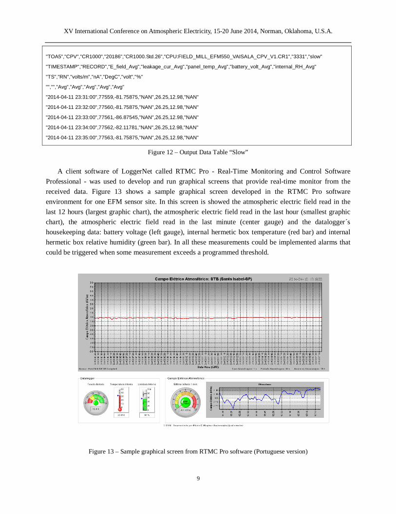
A client software of LoggerNet called RTMC Pro - Real-Time Monitoring and Control Software Professional - was used to develop and run graphical screens that provide real-time monitor from the received data. Figure 13 shows a sample graphical screen developed in the RTMC Pro software environment for one EFM sensor site. In this screen is showed the atmospheric electric field read in the last 12 hours (largest graphic chart), the atmospheric electric field read in the last hour (smallest graphic chart), the atmospheric electric field read in the last minute (center gauge) and the datalogger´s housekeeping data: battery voltage (left gauge), internal hermetic box temperature (red bar) and internal hermetic box relative humidity (green bar). In all these measurements could be implemented alarms that could be triggered when some measurement exceeds a programmed threshold.
Figure 13 – Sample graphical screen from RTMC Pro software (Portuguese version)
XV International Conference on Atmospheric Electricity, 15-20 June 2014, Norman, Oklahoma, U.S.A.
10
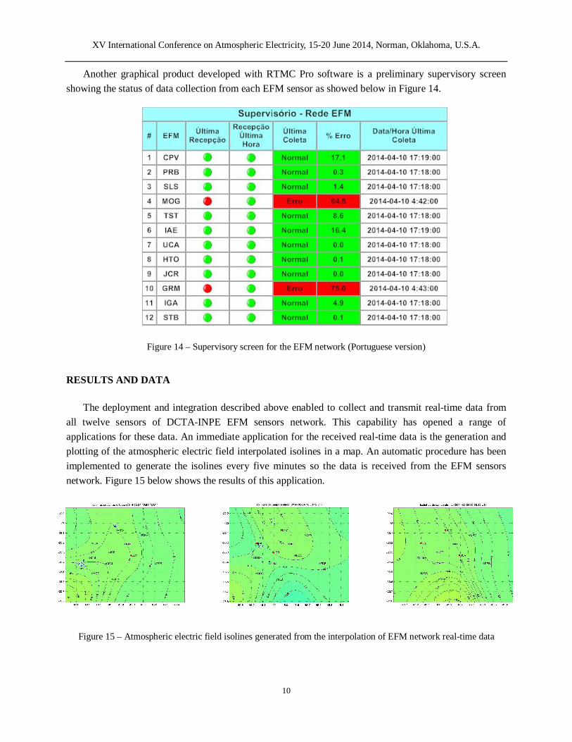
Another graphical product developed with RTMC Pro software is a preliminary supervisory screen showing the status of data collection from each EFM sensor as showed below in Figure 14.
Figure 14 – Supervisory screen for the EFM network (Portuguese version)
RESULTS AND DATA
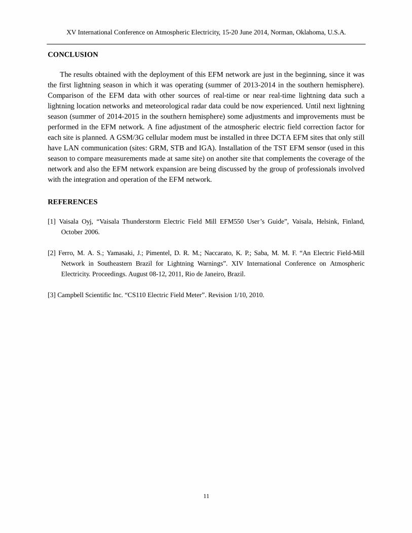
The deployment and integration described above enabled to collect and transmit real-time data from all twelve sensors of DCTA-INPE EFM sensors network. This capability has opened a range of applications for these data. An immediate application for the received real-time data is the generation and plotting of the atmospheric electric field interpolated isolines in a map. An automatic procedure has been implemented to generate the isolines every five minutes so the data is received from the EFM sensors network. Figure 15 below shows the results of this application.
Figure 15 – Atmospheric electric field isolines generated from the interpolation of EFM network real-time data
XV International Conference on Atmospheric Electricity, 15-20 June 2014, Norman, Oklahoma, U.S.A.
11
CONCLUSION
The results obtained with the deployment of this EFM network are just in the beginning, since it was the first lightning season in which it was operating (summer of 2013-2014 in the southern hemisphere). Comparison of the EFM data with other sources of real-time or near real-time lightning data such a lightning location networks and meteorological radar data could be now experienced. Until next lightning season (summer of 2014-2015 in the southern hemisphere) some adjustments and improvements must be performed in the EFM network. A fine adjustment of the atmospheric electric field correction factor for each site is planned. A GSM/3G cellular modem must be installed in three DCTA EFM sites that only still have LAN communication (sites: GRM, STB and IGA). Installation of the TST EFM sensor (used in this season to compare measurements made at same site) on another site that complements the coverage of the network and also the EFM network expansion are being discussed by the group of professionals involved with the integration and operation of the EFM network.
REFERENCES
[1] Vaisala Oyj, “Vaisala Thunderstorm Electric Field Mill EFM550 User’s Guide”, Vaisala, Helsink, Finland, October 2006.
[2] Ferro, M. A. S.; Yamasaki, J.; Pimentel, D. R. M.; Naccarato, K. P.; Saba, M. M. F. “An Electric Field-Mill
Network in Southeastern Brazil for Lightning Warnings”. XIV International Conference on Atmospheric Electricity. Proceedings. August 08-12, 2011, Rio de Janeiro, Brazil.
[3] Campbell Scientific Inc. “CS110 Electric Field Meter”. Revision 1/10, 2010.