Atmospheric and Fog Effects on Ultra-Wide Band Radar ...
10
sensors Article Atmospheric and Fog Effects on Ultra-Wide Band Radar Operating at Extremely High Frequencies Nezah Balal, Gad A. Pinhasi and Yosef Pinhasi * Faculty of Engineering, Ariel University, Ariel 40700, Israel; [email protected] (N.B.); [email protected] (G.A.P.) * Correspondence: [email protected]; Tel.: +972-3-9066272 Academic Editor: Assefa M. Melesse Received: 11 February 2016; Accepted: 17 May 2016; Published: 23 May 2016 Abstract: The wide band at extremely high frequencies (EHF) above 30 GHz is applicable for high resolution directive radars, resolving the lack of free frequency bands within the lower part of the electromagnetic spectrum. Utilization of ultra-wideband signals in this EHF band is of interest, since it covers a relatively large spectrum, which is free of users, resulting in better resolution in both the longitudinal and transverse dimensions. Noting that frequencies in the millimeter band are subjected to high atmospheric attenuation and dispersion effects, a study of the degradation in the accuracy and resolution is presented. The fact that solid-state millimeter and sub-millimeter radiation sources are producing low power, the method of continuous-wave wideband frequency modulation becomes the natural technique for remote sensing and detection. Millimeter wave radars are used as complementary sensors for the detection of small radar cross-section objects under bad weather conditions, when small objects cannot be seen by optical cameras and infrared detectors. Theoretical analysis for the propagation of a wide “chirped” Frequency-Modulated Continuous-Wave (FMCW) radar signal in a dielectric medium is presented. It is shown that the frequency-dependent (complex) refractivity of the atmospheric medium causes distortions in the phase of the reflected signal, introducing noticeable errors in the longitudinal distance estimations, and at some frequencies may also degrade the resolution. Keywords: extremely high frequencies; FMCW radar; atmosphere; millimeter waves; Tera-Hertz frequencies 1. Introduction Millimeter wave radar systems operating in multi-frequency or Frequency Modulated Continuous Wave (FMCW) mode were intensively studied over the recent years for a variety of applications such as collision avoidance in automobiles [1–3], remote sensing [4–6], concealed weapon detection for homeland security needs [7,8], helicopter and aircraft landing control and other related areas. The selection of operating frequencies in the millimeter wave regime and modulation techniques is an important issue in the design of active sensors and significantly depends on atmospheric propagation and penetration depth through various materials. Broadband FMCW radars enable high resolution in range and depth perception and in the detection of objects with a small radar cross-section. The demand for broadband radar systems and the deficiency of wide frequency gaps within the lower band spectra necessitate the utilization of higher frequencies at millimeter wavelengths in the extremely high frequencies (EHF) range above 30 GHz. The EHF band (30–300 GHz) covers a wide frequency range, which is relatively free of users. It offers many advantages for high resolution radars, enabling detection and imaging of concealed objects with a small radar cross-section. Among the practical advantages of using millimeter and sub-millimeter wavelength radar systems is the ability to employ smaller transmitting and receiving antennas. Millimeter wave radars also operate well under bad weather conditions such as fog and Sensors 2016, 16, 751; doi:10.3390/s16050751 www.mdpi.com/journal/sensors
Transcript of Atmospheric and Fog Effects on Ultra-Wide Band Radar ...

sensors
Article
Atmospheric and Fog Effects on Ultra-Wide BandRadar Operating at Extremely High Frequencies
Nezah Balal, Gad A. Pinhasi and Yosef Pinhasi *
Faculty of Engineering, Ariel University, Ariel 40700, Israel; [email protected] (N.B.); [email protected] (G.A.P.)* Correspondence: [email protected]; Tel.: +972-3-9066272
Academic Editor: Assefa M. MelesseReceived: 11 February 2016; Accepted: 17 May 2016; Published: 23 May 2016
Abstract: The wide band at extremely high frequencies (EHF) above 30 GHz is applicable for highresolution directive radars, resolving the lack of free frequency bands within the lower part of theelectromagnetic spectrum. Utilization of ultra-wideband signals in this EHF band is of interest,since it covers a relatively large spectrum, which is free of users, resulting in better resolution inboth the longitudinal and transverse dimensions. Noting that frequencies in the millimeter bandare subjected to high atmospheric attenuation and dispersion effects, a study of the degradationin the accuracy and resolution is presented. The fact that solid-state millimeter and sub-millimeterradiation sources are producing low power, the method of continuous-wave wideband frequencymodulation becomes the natural technique for remote sensing and detection. Millimeter wave radarsare used as complementary sensors for the detection of small radar cross-section objects under badweather conditions, when small objects cannot be seen by optical cameras and infrared detectors.Theoretical analysis for the propagation of a wide “chirped” Frequency-Modulated Continuous-Wave(FMCW) radar signal in a dielectric medium is presented. It is shown that the frequency-dependent(complex) refractivity of the atmospheric medium causes distortions in the phase of the reflectedsignal, introducing noticeable errors in the longitudinal distance estimations, and at some frequenciesmay also degrade the resolution.
Keywords: extremely high frequencies; FMCW radar; atmosphere; millimeter waves;Tera-Hertz frequencies
1. Introduction
Millimeter wave radar systems operating in multi-frequency or Frequency Modulated ContinuousWave (FMCW) mode were intensively studied over the recent years for a variety of applicationssuch as collision avoidance in automobiles [1–3], remote sensing [4–6], concealed weapon detectionfor homeland security needs [7,8], helicopter and aircraft landing control and other related areas.The selection of operating frequencies in the millimeter wave regime and modulation techniques is animportant issue in the design of active sensors and significantly depends on atmospheric propagationand penetration depth through various materials.
Broadband FMCW radars enable high resolution in range and depth perception and in thedetection of objects with a small radar cross-section. The demand for broadband radar systems and thedeficiency of wide frequency gaps within the lower band spectra necessitate the utilization of higherfrequencies at millimeter wavelengths in the extremely high frequencies (EHF) range above 30 GHz.
The EHF band (30–300 GHz) covers a wide frequency range, which is relatively free of users.It offers many advantages for high resolution radars, enabling detection and imaging of concealedobjects with a small radar cross-section. Among the practical advantages of using millimeter andsub-millimeter wavelength radar systems is the ability to employ smaller transmitting and receivingantennas. Millimeter wave radars also operate well under bad weather conditions such as fog and
Sensors 2016, 16, 751; doi:10.3390/s16050751 www.mdpi.com/journal/sensors

Sensors 2016, 16, 751 2 of 10
haze, when other sensors fail to detect objects, and thus serve as an alternative to infrared and visiblelight cameras. They are good candidates for landing assistance instrumentation measuring the heightfrom the ground during dust and haze conditions.
Some of the key challenges in the development of modern radar in the EHF band are theemerging effects during the propagation of electromagnetic radiation through the atmosphere.When millimeter wave radiation propagates in the atmospheric medium, it is subjected to selectivemolecular absorption [9–14]. Empirical and analytical models were suggested for evaluating millimeterand sub-millimeter wave propagation in the atmosphere. The transmission characteristics of theatmosphere in this band are shown in Figure 1 for different atmospheric water droplet concentrations,given by W0 in (g/m3). The calculations were performed using the millimeter propagation model(MPM) developed by Liebe [15–18]. Millimeter wave signals propagating in the atmosphere sufferfrequency-dependent absorptive and dispersive phenomena, causing distortions in amplitude andphase [19]. These effects should be considered in the realization of broadband radar systems [20–22].While in millimeter wave communications atmospheric attenuation is the main cause of the reductionin the signal-to-noise ratio and thus leads to bit error rate growth, in FMCW radars, we show thatatmospheric dispersion also plays an important role in the accuracy of distance measurements.
Sensors 2016, 16, 751 2 of 10
sub-millimeter wavelength radar systems is the ability to employ smaller transmitting and receiving antennas. Millimeter wave radars also operate well under bad weather conditions such as fog and haze, when other sensors fail to detect objects, and thus serve as an alternative to infrared and visible light cameras. They are good candidates for landing assistance instrumentation measuring the height from the ground during dust and haze conditions.
Some of the key challenges in the development of modern radar in the EHF band are the emerging effects during the propagation of electromagnetic radiation through the atmosphere. When millimeter wave radiation propagates in the atmospheric medium, it is subjected to selective molecular absorption [9–14]. Empirical and analytical models were suggested for evaluating millimeter and sub-millimeter wave propagation in the atmosphere. The transmission characteristics of the atmosphere in this band are shown in Figure 1 for different atmospheric water droplet concentrations, given by 0W in (g/m3). The calculations were performed using the millimeter propagation model (MPM) developed by Liebe [15–18]. Millimeter wave signals propagating in the atmosphere suffer frequency-dependent absorptive and dispersive phenomena, causing distortions in amplitude and phase [19]. These effects should be considered in the realization of broadband radar systems [20–22]. While in millimeter wave communications atmospheric attenuation is the main cause of the reduction in the signal-to-noise ratio and thus leads to bit error rate growth, in FMCW radars, we show that atmospheric dispersion also plays an important role in the accuracy of distance measurements.
(a) (b)
Figure 1. Atmospheric propagation factor in the EHF band: (a) attenuation coefficient 20 log( )e f in (dB/km); (b) group delay increment ' /d N f d c in (ps/km).
In the current paper, a general approach for studying ultra-wideband FMCW radars operating in the EHF band under conditions of fog and haze is developed. The study is aimed at pointing out the implications of how dispersive effects in the medium (and not only absorption) play a role on the performances of wideband FMCW radars. The numerical Millimeter-wave Propagation Model (MPM) [15,16] is employed for prediction of the atmospheric frequency response. The calculated propagation factor is used for the study of wide FMCW signal transmission through the atmosphere.
2. Propagation of a Linear FM Signal in a Dielectric Medium
We start with a general review of the description of electromagnetic radiation in the frequency domain. The fundamental principles of FMCW radars are also given here, mainly for convenience, defining the terms and notations used in the following discussion. The formulation we have developed is applied for the study of a linear FM (“chirp”) signal detected by a product detector after propagation and reflection from a target. We demonstrate the approach on a FMCW radar operating at millimeter and sub-millimeter wavelengths under fog conditions. We assume that the response of the components within the system is linear; this is a reasonable assumption as, though
0 50 100 150 200 250 300 35010
-2
10-1
100
101
102
Po
we
r A
tten
ua
tion
[d
B/k
m]
Frequency [GHz]
(a)
W0=0 g/m3
W0=0.1 mg/m3
W0=0.5 mg/m3
W0=1 mg/m3
50 100 150 200 250 300 350-5
0
5
10
15
20
25
Frequency [GHz]
d
[ps/
km]
(b)
W0=0 g/m3
W0=0.1 mg/m3
W0=0.5 mg/m3
W0=1 mg/m3
Figure 1. Atmospheric propagation factor in the EHF band: (a) attenuation coefficient 20logpeq ¨α p f qin (dB/km); (b) group delay increment ∆τd “ N1 p f q ¨ d{c in (ps/km).
In the current paper, a general approach for studying ultra-wideband FMCW radars operatingin the EHF band under conditions of fog and haze is developed. The study is aimed at pointing outthe implications of how dispersive effects in the medium (and not only absorption) play a role onthe performances of wideband FMCW radars. The numerical Millimeter-wave Propagation Model(MPM) [15,16] is employed for prediction of the atmospheric frequency response. The calculatedpropagation factor is used for the study of wide FMCW signal transmission through the atmosphere.
2. Propagation of a Linear FM Signal in a Dielectric Medium
We start with a general review of the description of electromagnetic radiation in the frequencydomain. The fundamental principles of FMCW radars are also given here, mainly for convenience,defining the terms and notations used in the following discussion. The formulation we have developedis applied for the study of a linear FM (“chirp”) signal detected by a product detector after propagationand reflection from a target. We demonstrate the approach on a FMCW radar operating at millimeterand sub-millimeter wavelengths under fog conditions. We assume that the response of the componentswithin the system is linear; this is a reasonable assumption as, though typical components have

Sensors 2016, 16, 751 3 of 10
non-linear characteristics, it is possible in practice to use an equalizer to reduce the significance ofthis problem.
In a FMCW radar (see Figure 2), a linear frequency-modulated signal (“chirp”) is transmittedtoward the target. The instantaneous frequency of the transmission is changing linearly according to:
f ptq “ fc `∆ f
Tsweept (1)
where the carrier frequency is fc and the frequency span ∆ f divided by the sweep time Tsweep is thecompression ratio of the linear FM signal. The transmitted signal can be presented as a carrier wave atfrequency fc modulated by a wideband signal:
ETptq “ Re!
AT ptq ¨ ej2π fct)
(2)
Sensors 2016, 16, 751 3 of 10
typical components have non-linear characteristics, it is possible in practice to use an equalizer to reduce the significance of this problem.
In a FMCW radar (see Figure 2), a linear frequency-modulated signal (“chirp”) is transmitted toward the target. The instantaneous frequency of the transmission is changing linearly according to:
csweep
ff t f t
T
(1)
where the carrier frequency is cf and the frequency span f divided by the sweep time sweepT is the compression ratio of the linear FM signal. The transmitted signal can be presented as a carrier wave at frequency cf modulated by a wideband signal:
2( ) Re cj f tT TE t A t e (2)
LPF
VCO
Product Detector
ET(t)
ER(t)=ET(t-) 0 T T+
fpeak
fm
V(t)
Figure 2. Block diagram of the linear FM radar.
Here TA t is a complex envelope, representing the baseband modulating signal. In the case of linear FM, the complex amplitude of the “chirp” is:
2expTsweep
fA t j t
T
(3)
Fourier transform of the transmitted field Equation (2) yields:
*1 1( )2 2T T c T cf f f f f E A A (4)
where T fA is the Fourier transform of the complex envelope TA t . The transmitted signal
directed to the target located at a distance d is scattered back and arrives at the receiver after propagating a total distance of 2d in the dielectric medium, and the “phasor-like” field presentation in the positive frequency domain is given by:
2( ) zj k f dR T cf f f e E A (5)
where zk f is the complex propagation factor of the electromagnetic field in the medium. The Fourier transform of the field is:
2, , j ftr f E r t e dt
E (6)
It is useful to present the time-dependent electric field in its analytic form, for which the Fourier transformation is given in positive frequencies [21]. The substitution of Equation (5) into Equation (6) results in the time-dependent signal obtained at the receiver input:
2( ) Re cj f tR RE t A t e (7)
The complex envelope of the received signal is:
Figure 2. Block diagram of the linear FM radar.
Here AT ptq is a complex envelope, representing the baseband modulating signal. In the case oflinear FM, the complex amplitude of the “chirp” is:
AT ptq “ expˆ
jπ∆ f
Tsweept2˙
(3)
Fourier transform of the transmitted field Equation (2) yields:
ETp f q “12
AT p f ´ fcq `12
AT˚ r´ p f ` fcqs (4)
where AT p f q is the Fourier transform of the complex envelope AT ptq. The transmitted signal directedto the target located at a distance d is scattered back and arrives at the receiver after propagating atotal distance of 2d in the dielectric medium, and the “phasor-like” field presentation in the positivefrequency domain is given by:
rERp f q “ AT p f ´ fcq ¨ e´j2kzp f q ¨d (5)
where kz p f q is the complex propagation factor of the electromagnetic field in the medium. The Fouriertransform of the field is:
E pr, f q “
`8ż
´8
E pr, tq ¨ e´j2π f tdt (6)

Sensors 2016, 16, 751 4 of 10
It is useful to present the time-dependent electric field in its analytic form, for which the Fouriertransformation is given in positive frequencies [21]. The substitution of Equation (5) into Equation (6)results in the time-dependent signal obtained at the receiver input:
ERptq “ Re!
AR ptq ¨ ej2π fct)
(7)
The complex envelope of the received signal is:
AR ptq “
`8ż
´8
AT p f q ¨ e´j2kzp f` fcq ¨dd f (8)
The local oscillator reference signal is formed from the same source as the transmitted FMCWsignal and it is mixed with the delayed echoes reflected from the target. The mixed signal is filtered toremove higher-order harmonics. The resulting signal at the output of the filter is:
rV ptq “ AT˚ ptq ¨ AR ptq
“ AT˚ ptq ¨
`8r
´8
AT p f q ¨ e´j2kzp f` fcq¨dd f(9)
The detected signal rV ptq is at baseband or intermediate frequencies. The distance to the target ismeasured via the instantaneous frequency resulting from the derivative:
f IF ptq “ ´1
2πddt
arctan
»
–
Im!
rV ptq)
Re!
rV ptq)
fi
fl (10)
If the signal is propagating in a vacuum, i.e., when the index of refraction is a constant n p fc q “ 1 ,the propagation factor is . As expected, the detected signal resulting from Equation (9) is a pure tone:
rV ptq “ exp
¨
˚
˚
˚
˚
˝
´j2π∆ f
Tsweep
2dc
loooomoooon
fm
t
`jπ ∆ fTsweep
´
2dc
¯2´ 2π fc
2dc
˛
‹
‹
‹
‹
‚
(11)
Here we define fm as the intermediate frequency (IF) obtained when the signal is propagating invacuum. At a single frequency, fm is proportional to the distance to the target:
d “Tsweepc
2∆ ffm (12)
It is important to note that the longitudinal range resolution depends on the frequencyresolution δ fm:
δd “Tsweepc
2∆ fδ fm (13)
Since the frequency resolution depends on the sweep duration δ fm « 1{Tsweep, the error in thedistance measurement is:
δd “c
2∆ f(14)
The range resolution is improved as the radar bandwidth increases. A frequency span of∆ f “ 10 GHz results in a longitudinal resolution of δdvacuum “ 1.5 cm, which is not dependent onthe distance (assuming a linear response of the medium). Very small objects can be detected while using
Sensors 2016, 16, 751 5 of 10
an ultra-wideband signal. Since the frequency sweep in the FMCW signal is very large, one shouldconsider the non-linearity that may emerge due to the inappropriate design of the radar RF chain [23].A linear-phase frequency response is required to keep the linearity of the chirp along its whole temporalduration. Also, non-linear characteristics may cause a distortion in the modulated wave, resultingin further degradation in the sensitivity and thus an accuracy reduction in distance measurements.To overcome this issue, multi-stage amplification should be applied including limitation of the powergain to stay within the back-off regime of the amplifiers.
In order to focus the study only on the atmospheric propagation effects, a completely linear chirpis assumed to be transmitted. It is assumed that the FMCW signal is transmitted and received by alinear system in order to explore the impact of the atmospheric medium. Dispersive behavior of theatmospheric medium will cause deviations in the frequency calculated in Equation (10), and thusproduce errors in the measured distance. We now demonstrate the effects of atmospheric fog on theresulting measured distance at millimeter wavelengths.
3. Millimeter Wave Propagation in the Atmosphere
The millimeter wave propagation model is based on a complex presentation of the refraction index:
n p f q “ 1` N p f q ˆ 10´6 (15)
The complex refractivity Np f q “ N0 ` N1p f q ´ jN2p f q is given in parts-per-million (ppm) [15,16].The propagation factor kz p f q can be written in terms of the index of refraction:
kz p f q “ 2π fc np f q “ ´j
2π fc
N2 p f q ˆ 10´6
loooooooooomoooooooooon
αp f q
`2π f
c
´
1` N0 ˆ 10´6¯
`
∆βp f qhkkkkkkkkkkikkkkkkkkkkj
2π fc
N1 p f q ˆ 10´6
loooooooooooooooooooooooooooomoooooooooooooooooooooooooooon
βp f q
(16)
where c is the speed of light in a vacuum. The attenuation factor is:
α p f q “ ´Im tkzp f qu “2π f
cN2 p f q ˆ 10´6 (17)
The wavenumber of the field is given by:
β p f q “ Re tkzp f qu“
2π fc
`
1` N0 ˆ 10´6˘`2π f
c N1 p f q ˆ 10´6 (18)
The group delay at a distance d is defined via the derivative of the wavenumber:
τd “d
2πdβd f
“ dc`
1` N0 ˆ 10´6˘` dc
”
N1 p f q ` f dN1d f
ı
ˆ 10´6 (19)
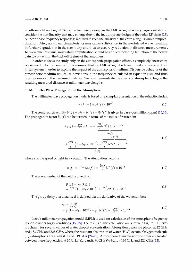
Liebe’s millimeter propagation model (MPM) is used for calculation of the atmospheric frequencyresponse under foggy conditions [15–18]. The results of this calculation are shown in Figure 1. Curvesare drawn for several values of water droplet concentration. Absorption peaks are placed at 22 GHzand 183 GHz and 325 GHz, where the resonant absorption of water (H2O) occurs. Oxygen molecule(O2) absorptions are at 60 GHz and 119 GHz [24–26]. Atmospheric transmission windows are locatedbetween these frequencies, at 35 GHz (Ka-band), 94 GHz (W-band), 130 GHz and 220 GHz [12].

Sensors 2016, 16, 751 6 of 10
4. Numerical Results
Now we examine the absorptive and dispersive effects of fog on the propagation of anultra-wideband ‘chirp’ transmitted at millimeter and sub-millimeter wavelengths and received by theFMCW detector. Note that both the attenuation coefficient α p f q and the wave number β p f q play a rolein the wave propagation due to their non-uniform frequency response. The resulting detection leadsto a deviation in the distance measurements. The MPM model also allows considerations of limitedvisibility due to fog and haze [16]. Fog and cloud conditions are characterized via the water dropletconcentration W (in (g/m3). Figure 1 shows the effect of different values of droplet concentration onthe attenuation and phase of a millimeter and THz wave.
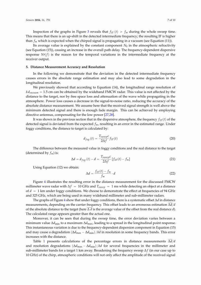
The intermediate frequency (IF) obtained at the output of the detector is given in Equation (10).It is proportional to the distance to the target, as can be seen in Equation (12). In the following, weconsider a wideband FMCW millimeter wave radar transmitting a chirp with ∆ f “ 10 GHz andTsweep “ 1 ms. A study of the resulting intermediate frequency is carried out for different frequencyregimes centered at 60 GHz, 94 GHz, 120 GHz, and 325 GHz. For a given frequency sweep, thenormalized detected IF frequency f IF ptq is shown in the graphs of Figure 3. The normalization is doneby dividing the resulting frequency by fm, which is the IF expected frequency if the wave would havepropagated in a vacuum.
Sensors 2016, 16, 751 6 of 10
considerations of limited visibility due to fog and haze [16]. Fog and cloud conditions are characterized via the water droplet concentration W (in (g/m3). Figure 1 shows the effect of different values of droplet concentration on the attenuation and phase of a millimeter and THz wave.
The intermediate frequency (IF) obtained at the output of the detector is given in Equation (10). It is proportional to the distance to the target, as can be seen in Equation (12). In the following, we consider a wideband FMCW millimeter wave radar transmitting a chirp with 10 GHzf and
1 mssweepT . A study of the resulting intermediate frequency is carried out for different frequency regimes centered at 60 GHz, 94 GHz, 120 GHz, and 325 GHz. For a given frequency sweep, the normalized detected IF frequency IFf t is shown in the graphs of Figure 3. The normalization is done by dividing the resulting frequency by mf , which is the IF expected frequency if the wave would have propagated in a vacuum.
(a) (b)
(c)
Figure 3. Variation of the instantaneous frequency / 1IF mf t f obtained for different frequencies
and fog conditions. (a) 60 GHz; (b) 94 GHz; (c) 325 GHz.
Inspection of the graphs in Figure 3 reveals that IF mf t f during the whole sweep time. This means that there is an up-shift in the detected intermediate frequency; the resulting IF is higher than mf which is expected when the chirped signal is propagating in a vacuum (see Equation (11)).
Its average value is explained by the constant component 0N in the atmospheric refractivity (see Equation (15)), causing an increase in the overall path delay. The frequency-dependent dispersive response '( )N f is the reason for the temporal variations in the intermediate frequency at the receiver output.
0 0.1 0.2 0.3 0.4 0.5 0.6 0.7 0.8 0.9 13.5
3.55
3.6
3.65
3.7
3.75
3.8x 10
-4
t/Tsweep
f IF(t
)/f m
-1
f0=60 [GHz] W
0=0 g/m3
W0=0.1 mg/m3
W0=0.5 mg/m3
W0=1 mg/m3
0 0.1 0.2 0.3 0.4 0.5 0.6 0.7 0.8 0.9 13.725
3.726
3.727
3.728
3.729
3.73
3.731
3.732
3.733
3.734
3.735x 10
-4
t/Tsweep
f IF(t
)/fm
-1
f0=94 [GHz]
W0=0 g/m3
W0=0.1 mg/m3
W0=0.5 mg/m3
W0=1 mg/m3
0 0.1 0.2 0.3 0.4 0.5 0.6 0.7 0.8 0.9 12.5
2.75
3
3.25
3.5
3.75
4
4.25
4.5x 10
-4
t/Tsweep
f IF(t
)/f m
-1
f0=325 [GHz] W
0=0 g/m3
W0=0.1 mg/m3
W0=0.5 mg/m3
W0=1 mg/m3
Figure 3. Variation of the instantaneous frequency f IF ptq { fm ´ 1 obtained for different frequenciesand fog conditions. (a) 60 GHz; (b) 94 GHz; (c) 325 GHz.
Sensors 2016, 16, 751 7 of 10
Inspection of the graphs in Figure 3 reveals that f IF ptq ą fm during the whole sweep time.This means that there is an up-shift in the detected intermediate frequency; the resulting IF is higherthan fm which is expected when the chirped signal is propagating in a vacuum (see Equation (11)).
Its average value is explained by the constant component N0 in the atmospheric refractivity(see Equation (15)), causing an increase in the overall path delay. The frequency-dependent dispersiveresponse N1p f q is the reason for the temporal variations in the intermediate frequency at thereceiver output.
5. Distance Measurement Accuracy and Resolution
In the following we demonstrate that the deviation in the detected intermediate frequencycauses errors in the absolute range estimation and may also lead to some degradation in thelongitudinal resolution.
We previously showed that according to Equation (14), the longitudinal range resolution ofδdvacuum “ 1.5 cm can be obtained by the wideband FMCW radar. This value is not affected by thedistance to the target, nor by free space loss and attenuation of the wave while propagating in theatmosphere. Power loss causes a decrease in the signal-to-noise ratio, reducing the accuracy of theabsolute distance measurement. We assume here that the received signal strength is well above theminimum detected signal and there is enough fade margin. This can be achieved by employingdirective antennas, compensating for the low power [27,28].
It was shown in the previous section that in the dispersive atmosphere, the frequency f IFptq of thedetected signal is deviated from the expected fm, resulting in an error in the estimated range. Underfoggy conditions, the distance to target is calculated by:
d f og ptq “Tsweepc
2∆ ff IFptq (20)
The difference between the measured value in foggy conditions and the real distance to the target(determined by fm) is:
∆d “ d f og ptq ´ d “Tsweepc
2∆ fr f IFptq ´ fms (21)
Using Equation (12) we obtain:
∆d “f IFptq ´ fm
fm¨ d (22)
Figure 4 illustrates the resulting error in the distance measurement for the discussed FMCWmillimeter wave radar with ∆ f “ 10 GHz and Tsweep “ 1 ms while detecting an object at a distanceof d “ 1 km under foggy conditions. We choose to demonstrate the effect at frequencies of 94 GHzand 325 GHz, which are being used in many wideband millimeter and sub-millimeter radars.
The graphs of Figure 4 show that under foggy conditions, there is a systematic offset ∆d in distancemeasurements, depending on the carrier frequency. This offset leads to an erroneous estimation ∆d{dof the absolute distance to the target (here ∆ d is the average value of the offset from the real distance d).The calculated range appears greater than the actual one.
Moreover, it can be seen that during the sweep time, the error deviation varies between aminimum value ∆dmin to a maximum ∆dmax, leading to a spread in the longitudinal point response.This instantaneous variation is due to the frequency-dependent dispersion component in Equation (15)and may cause a degradation p∆dmax ´ ∆dminq {δd in resolution in some frequency bands. This errorincreases with the distance.
Table 1 presents calculations of the percentage errors in distance measurements ∆d{dand resolution degradations p∆dmax ´ ∆dminq {δd for several frequencies in the millimeter andsub-millimeter bands for a target 1 km away. Broadening the frequency sweep ∆ f (in our case up to10 GHz) of the chirp, atmospheric conditions will not only affect the amplitude of the received signal

Sensors 2016, 16, 751 8 of 10
(due to absorption) but also its phase, leading to a reduction in accuracy of distance estimations. Thetransmission of wide FMCW signals in atmospheric absorption resonances causes some degradation inresolution, as seen at 60 GHz, 183 GHz and 325 GHz. In imaging radar systems [27], the time-varyingrange offset would degrade the longitudinal resolution.
Sensors 2016, 16, 751 7 of 10
5. Distance Measurement Accuracy and Resolution
In the following we demonstrate that the deviation in the detected intermediate frequency causes errors in the absolute range estimation and may also lead to some degradation in the longitudinal resolution.
We previously showed that according to Equation (14), the longitudinal range resolution of 1.5 cmvacuumd can be obtained by the wideband FMCW radar. This value is not affected by the
distance to the target, nor by free space loss and attenuation of the wave while propagating in the atmosphere. Power loss causes a decrease in the signal-to-noise ratio, reducing the accuracy of the absolute distance measurement. We assume here that the received signal strength is well above the minimum detected signal and there is enough fade margin. This can be achieved by employing directive antennas, compensating for the low power [27,28].
It was shown in the previous section that in the dispersive atmosphere, the frequency ( )IFf t of the detected signal is deviated from the expected mf , resulting in an error in the estimated range. Under foggy conditions, the distance to target is calculated by:
( )2sweep
fog IF
T cd t f t
f
(20)
The difference between the measured value in foggy conditions and the real distance to the target (determined by mf ) is:
( )2sweep
fog IF m
T cd d t d f t f
f
(21)
Using Equation (12) we obtain:
( )IF m
m
f t fd d
f
(22)
Figure 4 illustrates the resulting error in the distance measurement for the discussed FMCW millimeter wave radar with 10 GHzf and 1 mssweepT while detecting an object at a
distance of 1 kmd under foggy conditions. We choose to demonstrate the effect at frequencies of 94 GHz and 325 GHz, which are being used in many wideband millimeter and sub-millimeter radars.
(a) (b)
Figure 4. Cont.
0 0.1 0.2 0.3 0.4 0.5 0.6 0.7 0.8 0.9 135
35.5
36
36.5
37
37.5
38
t/Tsweep
d
[cm
]
f0=60 [GHz] W
0=0 g/m3
W0=0.1 mg/m3
W0=0.5 mg/m3
W0=1 mg/m3
0 0.1 0.2 0.3 0.4 0.5 0.6 0.7 0.8 0.9 137.25
37.26
37.27
37.28
37.29
37.3
37.31
37.32
37.33
37.34
37.35
t/Tsweep
d
[cm
]
f0=94 [GHz]
W0=0 g/m3
W0=0.1 mg/m3
W0=0.5 mg/m3
W0=1 mg/m3
Sensors 2016, 16, 751 8 of 10
(c)
Figure 4. The range error in atmospheric foggy conditions. (a) 60 GHz; (b) 94 GHz; (c) 325 GHz.
The graphs of Figure 4 show that under foggy conditions, there is a systematic offset d in distance measurements, depending on the carrier frequency. This offset leads to an erroneous estimation /d d of the absolute distance to the target (here d is the average value of the offset from the real distance d ). The calculated range appears greater than the actual one.
Moreover, it can be seen that during the sweep time, the error deviation varies between a minimum value mind to a maximum maxd , leading to a spread in the longitudinal point response.
This instantaneous variation is due to the frequency-dependent dispersion component in Equation (15) and may cause a degradation max min /d d d in resolution in some frequency bands. This error increases with the distance.
Table 1 presents calculations of the percentage errors in distance measurements /d d and resolution degradations max min /d d d for several frequencies in the millimeter and sub-millimeter bands for a target 1 km away. Broadening the frequency sweep f (in our case up to 10 GHz) of the chirp, atmospheric conditions will not only affect the amplitude of the received signal (due to absorption) but also its phase, leading to a reduction in accuracy of distance estimations. The transmission of wide FMCW signals in atmospheric absorption resonances causes some degradation in resolution, as seen at 60 GHz, 183 GHz and 325 GHz. In imaging radar systems [27], the time-varying range offset would degrade the longitudinal resolution.
Table 1. Distance accuracy /d d and resolution degradation max min /d d d when the
target is at a distance of 1 kmd .
Frequency (GHz) d
d
max mind d
d
23 0.03715% - 35 0.03725% - 60 0.03630% 173% 77 0.03735% - 94 0.037329% -
120 0.03715% - 183 0.03325% 700% 220 0.03785% - 325 0.03425% 833%
0 0.1 0.2 0.3 0.4 0.5 0.6 0.7 0.8 0.9 125
27.5
30
32.5
35
37.5
40
42.5
45
t/Tsweep
d
[cm
]
f0=325 [GHz] W
0=0 g/m3
W0=0.1 mg/m3
W0=0.5 mg/m3
W0=1 mg/m3
Figure 4. The range error in atmospheric foggy conditions. (a) 60 GHz; (b) 94 GHz; (c) 325 GHz.
Table 1. Distance accuracy ∆d{d and resolution degradation p∆dmax ´ ∆dminq {δd when the target is ata distance of d “ 1 km .
Frequency (GHz) ∆dd
∆dmax´∆dminffid
23 0.03715% -35 0.03725% -60 0.03630% 173%77 0.03735% -94 0.037329% -
120 0.03715% -183 0.03325% 700%220 0.03785% -325 0.03425% 833%

Sensors 2016, 16, 751 9 of 10
6. Conclusions
In this paper we developed a model to study the effect of fog on the distance accuracymeasurements using an ultra-wideband FMCW radar operating in the millimeter and sub-millimeterwave regimes. The developed model can be employed to calculate the radar performance at anyfrequency from 10 GHz up to 1 THz. The study demonstrates the effects of dispersive attenuationand phase on a detected radar signal. It is found that loss and dispersion in the atmospheric mediumcause a deviation in the frequency obtained at the output of the FMCW radar, leading to an erroneousestimation of the distance to the target. We found that foggy conditions significantly affect the accuracyof the ultra-wideband radar. If weather conditions are known (fog, mist, high humidity) or the transferfunction of the medium is estimated, these effects can be overcome by an equalizer and adaptivesystem. ‘Side information’ about the channel behavior may be used for calibration of the system andcompensating for the erroneous measurements. One should note that time-dependent variations inthe atmospheric medium lead to temporal fading and turbulence scintillation phenomena. However,in this paper we assume that temporal changes in weather conditions are much slower than the traveltime of the signal.
The obtained results are the physical bounds for accuracies in distance measurements as well asthe resolution. Technical design issues, such as system non-linearities, can cause further degradationthat should be considered. It is also interesting to note that in digital wireless communication widebandlinks operating in millimeter wavelengths, the dispersion of the atmospheric medium is expected toplay an equivalent role. The magnitude and phase response of the atmosphere will affect the transferof M-ary (multi) phase or frequency-shift keying signals, causing inter-symbol interference in thedemodulated data.
Author Contributions: Nezah Balal and Gad A. Pinhasi wrote and performed the simulations; Nezah Balal,Gad A. Pinhasi and Yosef Pinhasi contributed analysis tools; Yosef Pinhasi conceived the theory; Nezah Balal,Gad A. Pinhasi and Yosef Pinhasi wrote the paper.
Conflicts of Interest: The authors declare no conflict of interest.
References
1. Zhang, J.H.; Liu, G.S.; Gu, H.; Su, W.M. Stepped-FMCW waveform applied for mm-wave automotivecollision warning radar. J. Infrared Millim. Waves 2000, 19, 413–418.
2. Moldovan, E.; Tatu, S.O.; Gaman, T.; Wu, K.; Bosisio, R.G. A new 94 GHz six-port collision avoidance radarsensor. IEEE Trans. Microw. Theory Tech. 2004, 52, 751–759. [CrossRef]
3. Wang, T.; Zheng, N.; Xin, J.; Ma, Z. Integrating millimeter wave radar with a monocular vision sensor foron-road obstacle detection applications. Sensors 2011, 11, 8992–9008. [CrossRef] [PubMed]
4. Caris, M.; Stanko, S.; Sommer, R.; Wahlen, A.; Leuther, A.; Tessmann, A.; Malanowski, M.; Samczyski, P.;Kulpa, K.; Cohen, M.; et al. SARape-Synthetic Aperture Radar for all weather penetrating UAV Application.In Proceedings of the International Radar Symposium 2013, Dresden, Germany, 19–21 June 2013.
5. Wallace, H.B. Analysis of RF imaging applications at frequencies over 100 GHz. Appl. Opt. 2010, 49, E38–E47.[CrossRef] [PubMed]
6. Starzer, F.; Fischer, A.; Forstner, H.P.; Knapp, H.; Wiesinger, F.; Stelzer, A. A fully integrated 77 GHzradar transmitter based on a low phase-noise 19.25 GHz fundamental VCO. In Proceedings of the IEEEBipolar/BiCMOS Circuits and Technology Meeting (BCTM), Austin, TX, USA, 4–6 October 2010.
7. Semenov, A.D.; Richter, H.; Böttger, U.; Hübers, H.W. Imaging Terahertz Radar for Security Applications.In Proceedings of the Terahertz for Military and Security Applications VI, Orlando, FL, USA, 16 March 2008.
8. Cooper, K.B.; Dengler, R.J.; Chattopadhyay, G.; Schlecht, E.; Gill, J.; Skalare, A.; Mehdi, I.; Siegel, P.H. AHigh-Resolution Imaging Radar at 580 GHz. IEEE Microw. Wirel. Compon. Lett. 2008, 18, 64–66. [CrossRef]
9. Crane, R.K. Propagation phenomena affecting satellite communication systems operating in the centimeterand millimeter wavelength bands. IEEE Proc. 1971, 59, 173–188. [CrossRef]
10. Crane, R.K. Fundamental limitations caused by RF propagation. IEEE Proc. 1981, 69, 196–209. [CrossRef]11. Ippolito, L.J. Radio propagation for space communication systems. IEEE Proc. 1981, 69, 697–727. [CrossRef]

Sensors 2016, 16, 751 10 of 10
12. Liebe, H.J. Atmospheric EHF window transparencies near 35, 90, 140 and 220 GHz. IEEE Trans. Antennas Propag.1983, 31, 127–135. [CrossRef]
13. Bohlander, R.A.; McMillan, R.W. Atmospheric effects on near millimeter wave propagation. IEEE Proc. 1985,73, 49–60. [CrossRef]
14. Currie, N.C.; Brown, C.E. Principles and Applications of Millimeter-Wave Radar; Artech House: Norwood, MA,USA, 1987.
15. Liebe, H.J. An updated model for millimeter wave propagation in moist air. Radio Sci. 1985, 20, 1069–1089.[CrossRef]
16. Liebe, H.J. MPM—An atmospheric millimeter-wave propagation model. Int. J. Infrared Millim. Waves 1989,10, 631–650. [CrossRef]
17. Liebe, H.J.; Manabe, T.; Hufford, G.A. Millimeter-wave attenuation and delay rates due to fog/cloudconditions. IEEE Trans. Antennas Propag. 1989, 37, 1617–1623. [CrossRef]
18. Liebe, H.J.; Hufford, G.A.; Manabe, T. A model for the complex permittivity of water at frequencies below1 THz. Int. J. Infrared Millim. Waves 1991, 12, 659–675. [CrossRef]
19. Attenuation by Atmospheric Gases, International Telecommunication Union. Available online: https://www.itu.int/dms_pubrec/itu-r/rec/p/R-REC-P.676-10-201309-I!!PDF-E.pdf (accessed on 23 May 2016).
20. Pinhasi, Y.; Yahalom, A.; Harpaz, O.; Vilner, G. Study of ultra wideband transmission in the extremely highfrequency (EHF) band. IEEE Trans. Antennas Propag. 2004, 52, 2833–2842. [CrossRef]
21. Pinhasi, Y.; Yahalom, A. Spectral Characteristics of Gaseous Media and their effects on Propagation ofUltra-Wideband Radiation in the Millimeter Wavelengths. J. Non-Cryst. Sol. 2005, 351, 2925–2928. [CrossRef]
22. Pinhasi, Y.; Yahalom, A.; Pinhasi, G.A. Propagation Analysis of Ultra-Short Pulses in Resonant DielectricMedia. J. Opt. Soc. Am. B 2009, 26, 2404–2413. [CrossRef]
23. Meta, A.; Hoogeboom, P.; Ligthart, L.P. Range non-linearities correction in FMCW SAR. In Proceedingsof the IEEE International Symposium on Geoscience and Remote Sensing (IGARSS’06), Denver, CO, USA,31 July–4 August 2006.
24. Van Vleck, J.H. The absorption of microwaves by oxygen. Phys. Rev. 1947, 71, 413–424. [CrossRef]25. Rosenkranz, P.W. Shape of the 5 mm oxygen band in the atmosphere. IEEE Trans. Antennas Propag. 1975, 23,
498–506. [CrossRef]26. Liebe, H.J.; Rosenkranz, P.W.; Hufford, G.A. Atmospheric 60 GHz oxygen spectrum: New laboratory
measurements and line parameters. J. Quant. Spectrosc. Radiat. Transf. 1992, 48, 629–643. [CrossRef]27. Kapilevich, B.; Pinhasi, Y.; Arusi, R.; Anisimov, M.; Hardon, D.; Litvak, B.; Wool, Y. 330 GHz FMCW Image
Sensor for Homeland Security Applications. J. Infrared Millim. Terahertz Waves 2010, 31, 1370–1381. [CrossRef]28. Etinger, A.; Balal, N.; Litvak, B.; Einat, M.; Kapilevich, B.; Pinhasi, Y. Non-Imaging MM-Wave FMCW Sensor
for Pedestrian Detection. IEEE Sens. J. 2014, 14, 1232–1237. [CrossRef]
© 2016 by the authors; licensee MDPI, Basel, Switzerland. This article is an open accessarticle distributed under the terms and conditions of the Creative Commons Attribution(CC-BY) license (http://creativecommons.org/licenses/by/4.0/).