ATM SECURITY USING GSM TECHNOLOGY · 2018-06-14 · ATM SECURITY USING GSM TECHNOLOGY Sudhakar...
13
International Research Journal of Engineering and Technology (IRJET) e-ISSN: 2395-0056 Volume: 05 Issue: 06 | June-2018 www.irjet.net p-ISSN: 2395-0072 © 2018, IRJET | Impact Factor value: 6.171 | ISO 9001:2008 Certified Journal | Page 897 ATM SECURITY USING GSM TECHNOLOGY Sudhakar Hallur 1 ,Manjunath Bajantri 2 , Sagar Santaji 3 1,3 Assistant Professor, Dept. of ECE, KLSGIT, Belagavi 2 Associate Software Engineer, L&T, Bengaluru --------------------------------------------------------------------------***--------------------------------------------------------------------- Abstract: Automated Teller Machine (ATM)’s now a days are extensively used all over the world for the withdrawal of cash. A unique card is issued for each user along with the unique code provided to him so as to the person may do all his transactions personally without anyone getting known. Since transactions are extensively secure there is no much more security required but in countries like India its very necessary to have a physical security to the machine. A provision to give physical security to the machine is being discussed over here in this paper presented over here. Keywords: ATM, security, power saving, transmission, control. 1. INTRODUCTION Since ATM’s have been getting theft these recent days, it has become very much necessary to increase the security of the ATM machines. A single CCTV camera situated at the corner of the ATM isn’t enough to provide much security since it only captures the video footage of what have been going on in the ATM but doesn’t take any measures as such the thief is imprisoned and handovered to the law. Since the thief shouldn’t escape from the ATM machine, the objective of this project is to handover the culprit to the police by making him stay inside by automatically closing of the door due to the damage done to the machine and simultaneously making him unconscious using toxic gas and at the same time informing the bank and police station about the activities that has been occurring in the ATM cabin. 1.1. ATM Machine In modern era ATM system is very essential part of our life. It makes very easy our transactions which was very tedious in early time. It was first used in 1939. Nowadays, about 1.5 million are installed worldwide. In consideration of ATM, there are different aspects that should be considered. First, one has to have an idea about the communication within ATMs. Second the issue of security is of paramount importance because all over the world, there is increasing use of ATMs and the risk of hacking turn to a reality more than ever before. In the past, the function of the ATM was to deliver cash in the form of bank notes and to debit corresponding bank account. Cards were used to identify the user. As for withdrawal of money, different methods are used. For instance, punched cards were used. By the use of such cards, only one payment was authorized. Thereby, a user had to get a supply of cards from his/her bank because the punched cards were not returned to the user. Another example was the use of a magnetic card which had a limited life. The use of such cards allowed; for instance twenty withdrawals of money. For beginning, personal identification number (PIN) has been of very great importance in the overall operation. 1.2. Keypad To do the transactions in an ATM, its very much necessary to have a keypad consisting of alphabets and numbers. Such a keypad is also known as an Alphanumeric Keypad. Each number in the keypad has a particular frequency associated with it through which the number pressed gets detected. The figure below shows keypad. Fig 1. Keypad of an ATM Machine 1.3. Internal Structure of an ATM The internal structure of the ATM is as described as shown in the fig 2. It consists of 5 main parts. They are as follows: Display, Card Reader, CPU, Cash Cartridge and Vault Housing. Fig 2. ATM Internal Structure
Transcript of ATM SECURITY USING GSM TECHNOLOGY · 2018-06-14 · ATM SECURITY USING GSM TECHNOLOGY Sudhakar...
International Research Journal of Engineering and Technology (IRJET) e-ISSN: 2395-0056
Volume: 05 Issue: 06 | June-2018 www.irjet.net p-ISSN: 2395-0072
© 2018, IRJET | Impact Factor value: 6.171 | ISO 9001:2008 Certified Journal | Page 897
ATM SECURITY USING GSM TECHNOLOGY
Sudhakar Hallur1,Manjunath Bajantri2, Sagar Santaji3
1,3Assistant Professor, Dept. of ECE, KLSGIT, Belagavi 2Associate Software Engineer, L&T, Bengaluru
--------------------------------------------------------------------------***---------------------------------------------------------------------Abstract: Automated Teller Machine (ATM)’s now a days are extensively used all over the world for the withdrawal of cash. A unique card is issued for each user along with the unique code provided to him so as to the person may do all his transactions personally without anyone getting known. Since transactions are extensively secure there is no much more security required but in countries like India its very necessary to have a physical security to the machine. A provision to give physical security to the machine is being discussed over here in this paper presented over here.
Keywords: ATM, security, power saving, transmission, control.
1. INTRODUCTION
Since ATM’s have been getting theft these recent days, it has become very much necessary to increase the security of the ATM machines. A single CCTV camera situated at the corner of the ATM isn’t enough to provide much security since it only captures the video footage of what have been going on in the ATM but doesn’t take any measures as such the thief is imprisoned and handovered to the law. Since the thief shouldn’t escape from the ATM machine, the objective of this project is to handover the culprit to the police by making him stay inside by automatically closing of the door due to the damage done to the machine and simultaneously making him unconscious using toxic gas and at the same time informing the bank and police station about the activities that has been occurring in the ATM cabin.
1.1. ATM Machine
In modern era ATM system is very essential part of our life. It makes very easy our transactions which was very tedious in early time. It was first used in 1939. Nowadays, about 1.5 million are installed worldwide.
In consideration of ATM, there are different aspects that should be considered. First, one has to have an idea about the communication within ATMs. Second the issue of security is of paramount importance because all over the world, there is increasing use of ATMs and the risk of hacking turn to a reality more than ever before. In the past, the function of the ATM was to deliver cash in the
form of bank notes and to debit corresponding bank account. Cards were used to identify the user. As for withdrawal of money, different methods are used. For instance, punched cards were used. By the use of such cards, only one payment was authorized. Thereby, a user had to get a supply of cards from his/her bank because the punched cards were not returned to the user. Another example was the use of a magnetic card which had a limited life. The use of such cards allowed; for instance twenty withdrawals of money. For beginning, personal identification number (PIN) has been of very great importance in the overall operation.
1.2. Keypad
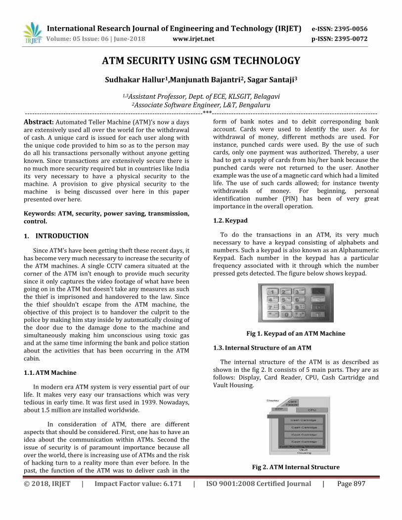
To do the transactions in an ATM, its very much necessary to have a keypad consisting of alphabets and numbers. Such a keypad is also known as an Alphanumeric Keypad. Each number in the keypad has a particular frequency associated with it through which the number pressed gets detected. The figure below shows keypad.
Fig 1. Keypad of an ATM Machine
1.3. Internal Structure of an ATM
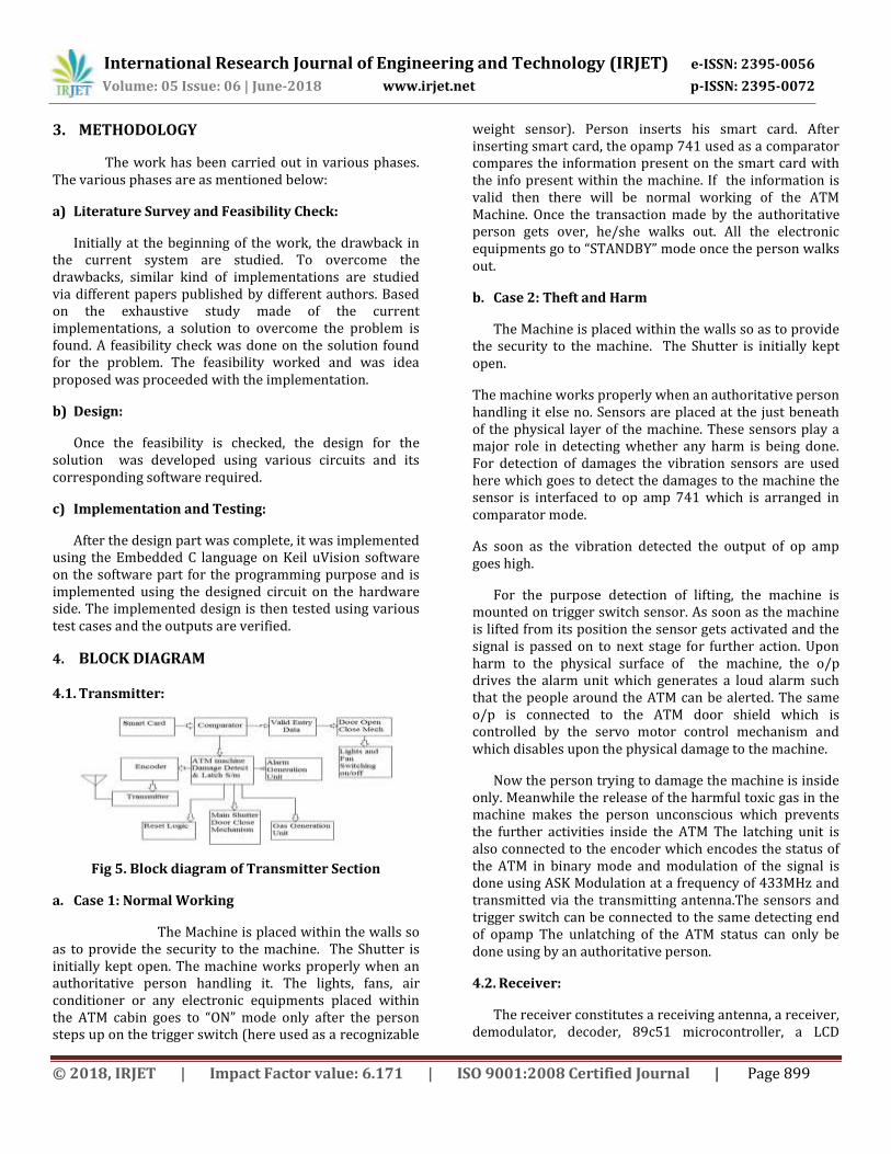
The internal structure of the ATM is as described as shown in the fig 2. It consists of 5 main parts. They are as follows: Display, Card Reader, CPU, Cash Cartridge and Vault Housing.
Fig 2. ATM Internal Structure

International Research Journal of Engineering and Technology (IRJET) e-ISSN: 2395-0056
Volume: 05 Issue: 06 | June-2018 www.irjet.net p-ISSN: 2395-0072
© 2018, IRJET | Impact Factor value: 6.171 | ISO 9001:2008 Certified Journal | Page 898
1.4. Personal Identification Number
Each user is given a personal identification number or a unique identification number to access the accounts. The personal identification number may be in the format as XXXX which may be reset in cases of emergency like theft etc.
1.5. Types of Attacks on the ATM Machine
The ATM Machines are not secure unless and until some physical protection methods are provided. The various types of attacks are as listed in the figure 3.
Fig 3. Attacks on ATM Machine
1.6. GSM Technology
Global System for Mobile Communications (GSM) is a standard set developed by the European Telecom Standards Institute (ETSI) to describe protocols for second generation (2G) digital cellular networks used by mobile phones. The GSM standard was developed as a replacement for first generation (1G) analog cellular networks, and originally described a digital, circuit switched network optimized for duplex voice telephony. This was expanded over time to include data communications, first by circuit switched transport, then packet data transport via GPRS (General Packet Radio Services) and EDGE (Enhanced Data rates for GSM Evolution or EGPRS). This was further used to implement 3G, 4G and 5G networks. The GSM time frame is being given in the figure 4.
Fig 4. GSM Time slot
1.7. Toxic Gases
A compressed gas or vapor that has a median lethal concentration (LC50) in air of 200 parts per million (ppm)
by volume, or 2 milligrams per liter of mist, fume, or dust, when administered by continuous inhalation for some few seconds causes unconsciousness for an hour or two but doesn’t result in a death of a person. Ex: Chloroform.
2. LITERATURE SURVEY
Madu and Maggie (2002) pointed out that the concern of customers about security and privacy, while using this service, is a major cause of their dissatisfaction. Ihejiahi (2009) expressed concern about the lack of cooperation among banks in the fight to stem the incidence of ATM frauds now plaguing the industry. He expressed that the silence among banks on ATM frauds makes it difficult for banks to share vital information that will help curb the menace. Obiano (2009) blamed the menace of ATM frauds on indiscriminate issue of ATM card without regard to the customer’s literacy level. According to him one of the frequent causes of fraud is when customers are careless with their cards and PIN numbers as well as their response to unsolicited e-mail and text messages to provide their card details. Omankhanleu (2009) opined that the current upsurge and nefarious activities of Automated Teller Machine (ATM) fraudster is threatening electronic payment system in the nation’s banking sector with users threatening massive dumping of the cards if the unwholesome act is not checked. Adeloye (2008) identified security as well as power outage as major challenges facing the ATM users in Nigeria. Brunner et al. (2004) in their study concluded that the location of ATM is a high determinant to fraud or crime carried out at ATM point. From this research over 75% of the respondents affirm that the location of ATM in secluded place contribute to the fraud perpetuated at ATM point. ATM within the banking premises is more secure than ATMs outside the bank premises. Also, it is obvious that the location of ATM in attractive place does not make it prone for fraud. Diebold (2002) in his view states that the major form of ATM fraud is PIN theft which is carried out by various means; skimming, shoulder surfing, camera, key pad recorder etc. This study elucidates that the common type of fraud perpetuated is PIN theft which is mostly as a result of congestion at ATM points. Other forms of fraud that were enumerated by respondents were; force withdrawal, card theft, and skimming and congestion method fraud at ATM. Cynthia (2000) states that the 24 hours access to the ATM machine is a double edge sword, it has both advantage and disadvantage. Roli Bansal et al (2011) pointed out that amongst all the fingerprint features, minutia point features with corresponding orientation maps are unique enough to discriminate amongst fingerprints robustly; the minutiae feature representation reduces the complex fingerprint recognition problem to a point pattern matching problem.
International Research Journal of Engineering and Technology (IRJET) e-ISSN: 2395-0056
Volume: 05 Issue: 06 | June-2018 www.irjet.net p-ISSN: 2395-0072
© 2018, IRJET | Impact Factor value: 6.171 | ISO 9001:2008 Certified Journal | Page 899
3. METHODOLOGY
The work has been carried out in various phases. The various phases are as mentioned below:
a) Literature Survey and Feasibility Check:
Initially at the beginning of the work, the drawback in the current system are studied. To overcome the drawbacks, similar kind of implementations are studied via different papers published by different authors. Based on the exhaustive study made of the current implementations, a solution to overcome the problem is found. A feasibility check was done on the solution found for the problem. The feasibility worked and was idea proposed was proceeded with the implementation.
b) Design:
Once the feasibility is checked, the design for the solution was developed using various circuits and its corresponding software required.
c) Implementation and Testing:
After the design part was complete, it was implemented using the Embedded C language on Keil uVision software on the software part for the programming purpose and is implemented using the designed circuit on the hardware side. The implemented design is then tested using various test cases and the outputs are verified.
4. BLOCK DIAGRAM
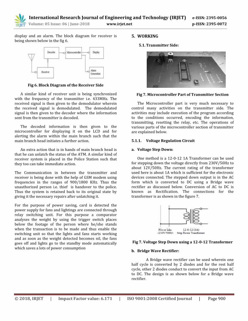
4.1. Transmitter:
Fig 5. Block diagram of Transmitter Section
a. Case 1: Normal Working
The Machine is placed within the walls so as to provide the security to the machine. The Shutter is initially kept open. The machine works properly when an authoritative person handling it. The lights, fans, air conditioner or any electronic equipments placed within the ATM cabin goes to “ON” mode only after the person steps up on the trigger switch (here used as a recognizable
weight sensor). Person inserts his smart card. After inserting smart card, the opamp 741 used as a comparator compares the information present on the smart card with the info present within the machine. If the information is valid then there will be normal working of the ATM Machine. Once the transaction made by the authoritative person gets over, he/she walks out. All the electronic equipments go to “STANDBY” mode once the person walks out.
b. Case 2: Theft and Harm
The Machine is placed within the walls so as to provide the security to the machine. The Shutter is initially kept open.
The machine works properly when an authoritative person handling it else no. Sensors are placed at the just beneath of the physical layer of the machine. These sensors play a major role in detecting whether any harm is being done. For detection of damages the vibration sensors are used here which goes to detect the damages to the machine the sensor is interfaced to op amp 741 which is arranged in comparator mode.
As soon as the vibration detected the output of op amp goes high.
For the purpose detection of lifting, the machine is mounted on trigger switch sensor. As soon as the machine is lifted from its position the sensor gets activated and the signal is passed on to next stage for further action. Upon harm to the physical surface of the machine, the o/p drives the alarm unit which generates a loud alarm such that the people around the ATM can be alerted. The same o/p is connected to the ATM door shield which is controlled by the servo motor control mechanism and which disables upon the physical damage to the machine.
Now the person trying to damage the machine is inside only. Meanwhile the release of the harmful toxic gas in the machine makes the person unconscious which prevents the further activities inside the ATM The latching unit is also connected to the encoder which encodes the status of the ATM in binary mode and modulation of the signal is done using ASK Modulation at a frequency of 433MHz and transmitted via the transmitting antenna.The sensors and trigger switch can be connected to the same detecting end of opamp The unlatching of the ATM status can only be done using by an authoritative person.
4.2. Receiver:
The receiver constitutes a receiving antenna, a receiver, demodulator, decoder, 89c51 microcontroller, a LCD
International Research Journal of Engineering and Technology (IRJET) e-ISSN: 2395-0056
Volume: 05 Issue: 06 | June-2018 www.irjet.net p-ISSN: 2395-0072
© 2018, IRJET | Impact Factor value: 6.171 | ISO 9001:2008 Certified Journal | Page 900
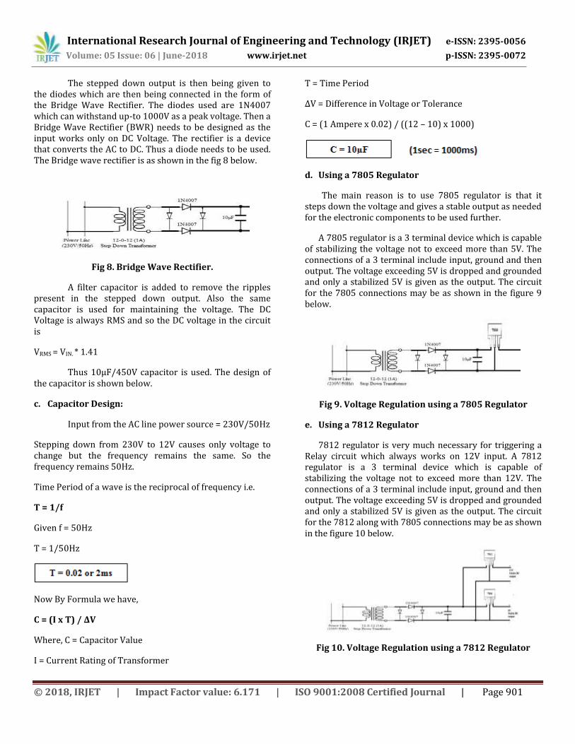
display and an alarm. The block diagram for receiver is being shown below in the fig 6.
Fig 6. Block Diagram of the Receiver Side
A similar kind of receiver unit is being synchronized with the frequency of the transmitter i.e. 433MHz. The received signal is then given to the demodulator wherein the received signal is demodulated. The demodulated signal is then given to the decoder where the information sent from the transmitter is decoded.
The decoded information is then given to the microcontroller for displaying it on the LCD and for alerting the alarm within the main branch such that the main branch head initiates a further action.
An extra action that is in hands of main branch head is that he can unlatch the status of the ATM. A similar kind of receiver system is placed in the Police Station such that they too can take immediate action.
The Communication in between the transmitter and receiver is being done with the help of GSM modem using frequencies in the ranges of 900/1800 KHz. Thus the unauthorized person i.e. thief is handover to the police. Thus the system is retained back to its original state by giving it the necessary repairs after unlatching it.
For the purpose of power saving, card is detected the power supply for fans and lightings are connected through relay switching unit. For this purpose a comparator analyses the weight by using the trigger switch places below the footage of the person where he/she stands when the transaction is to be made and thus enable the switching unit so that the lights and fans starts working and as soon as the weight detected becomes nil, the fans goes off and lights go to the standby mode automatically which saves a lots of power consumption
5. WORKING
5.1. Transmitter Side:
Fig 7. Microcontroller Part of Transmitter Section
The Microcontroller part is very much necessary to control many activities on the transmitter side. The activities may include execution of the program according to the conditions occurred, encoding the information, transmitting, resetting the relay, etc. The operations of various parts of the microcontroller section of transmitter are explained below.
5.1.1. Voltage Regulation Circuit
a. Voltage Step Down:
One method is a 12-0-12 1A Transformer can be used for stepping down the voltage directly from 230V/50Hz to about 12V/50Hz. The current rating of the transformer used here is about 1A which is sufficient for the electronic devices connected. The stepped down output is in the AC form which is converted to DC using a Bridge wave rectifier as discussed below. Conversion of AC to DC is known as Rectification. The connections for the transformer is as shown in the figure 7.
Fig 7. Voltage Step Down using a 12-0-12 Transformer
b. Bridge Wave Rectifier:
A Bridge wave rectifier can be used wherein one half cycle is converted by 2 diodes and for the rest half cycle, other 2 diodes conduct to convert the input from AC to DC. The design is as shown below for a Bridge wave rectifier.
International Research Journal of Engineering and Technology (IRJET) e-ISSN: 2395-0056
Volume: 05 Issue: 06 | June-2018 www.irjet.net p-ISSN: 2395-0072
© 2018, IRJET | Impact Factor value: 6.171 | ISO 9001:2008 Certified Journal | Page 901
The stepped down output is then being given to the diodes which are then being connected in the form of the Bridge Wave Rectifier. The diodes used are 1N4007 which can withstand up-to 1000V as a peak voltage. Then a Bridge Wave Rectifier (BWR) needs to be designed as the input works only on DC Voltage. The rectifier is a device that converts the AC to DC. Thus a diode needs to be used. The Bridge wave rectifier is as shown in the fig 8 below.
Fig 8. Bridge Wave Rectifier.
A filter capacitor is added to remove the ripples present in the stepped down output. Also the same capacitor is used for maintaining the voltage. The DC Voltage is always RMS and so the DC voltage in the circuit is
VRMS = VIN. * 1.41
Thus 10µF/450V capacitor is used. The design of the capacitor is shown below.
c. Capacitor Design:
Input from the AC line power source = 230V/50Hz
Stepping down from 230V to 12V causes only voltage to change but the frequency remains the same. So the frequency remains 50Hz.
Time Period of a wave is the reciprocal of frequency i.e.
T = 1/f
Given f = 50Hz
T = 1/50Hz
Now By Formula we have,
C = (I x T) / ΔV
Where, C = Capacitor Value
I = Current Rating of Transformer
T = Time Period
ΔV = Difference in Voltage or Tolerance
C = (1 Ampere x 0.02) / ((12 – 10) x 1000)
d. Using a 7805 Regulator
The main reason is to use 7805 regulator is that it steps down the voltage and gives a stable output as needed for the electronic components to be used further.
A 7805 regulator is a 3 terminal device which is capable of stabilizing the voltage not to exceed more than 5V. The connections of a 3 terminal include input, ground and then output. The voltage exceeding 5V is dropped and grounded and only a stabilized 5V is given as the output. The circuit for the 7805 connections may be as shown in the figure 9 below.
Fig 9. Voltage Regulation using a 7805 Regulator
e. Using a 7812 Regulator
7812 regulator is very much necessary for triggering a Relay circuit which always works on 12V input. A 7812 regulator is a 3 terminal device which is capable of stabilizing the voltage not to exceed more than 12V. The connections of a 3 terminal include input, ground and then output. The voltage exceeding 5V is dropped and grounded and only a stabilized 5V is given as the output. The circuit for the 7812 along with 7805 connections may be as shown in the figure 10 below.
Fig 10. Voltage Regulation using a 7812 Regulator
International Research Journal of Engineering and Technology (IRJET) e-ISSN: 2395-0056
Volume: 05 Issue: 06 | June-2018 www.irjet.net p-ISSN: 2395-0072
© 2018, IRJET | Impact Factor value: 6.171 | ISO 9001:2008 Certified Journal | Page 902
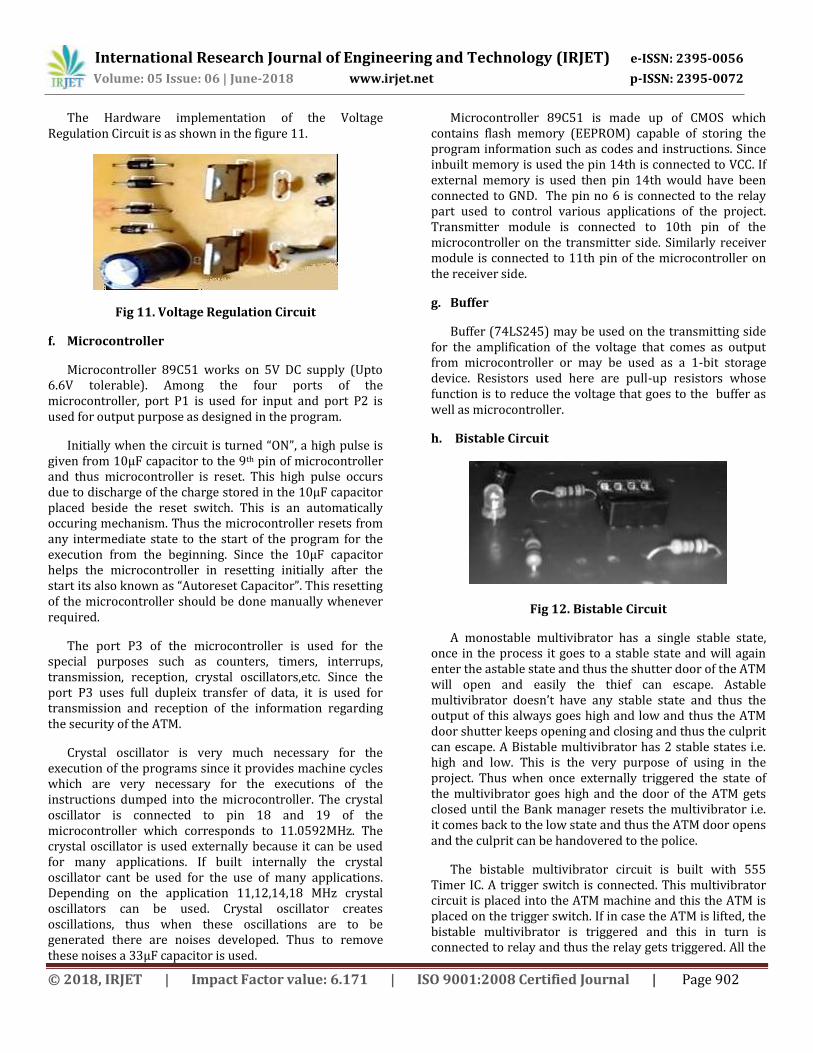
The Hardware implementation of the Voltage Regulation Circuit is as shown in the figure 11.
Fig 11. Voltage Regulation Circuit
f. Microcontroller
Microcontroller 89C51 works on 5V DC supply (Upto 6.6V tolerable). Among the four ports of the microcontroller, port P1 is used for input and port P2 is used for output purpose as designed in the program.
Initially when the circuit is turned “ON”, a high pulse is given from 10µF capacitor to the 9th pin of microcontroller and thus microcontroller is reset. This high pulse occurs due to discharge of the charge stored in the 10µF capacitor placed beside the reset switch. This is an automatically occuring mechanism. Thus the microcontroller resets from any intermediate state to the start of the program for the execution from the beginning. Since the 10µF capacitor helps the microcontroller in resetting initially after the start its also known as “Autoreset Capacitor”. This resetting of the microcontroller should be done manually whenever required.
The port P3 of the microcontroller is used for the special purposes such as counters, timers, interrups, transmission, reception, crystal oscillators,etc. Since the port P3 uses full dupleix transfer of data, it is used for transmission and reception of the information regarding the security of the ATM.
Crystal oscillator is very much necessary for the execution of the programs since it provides machine cycles which are very necessary for the executions of the instructions dumped into the microcontroller. The crystal oscillator is connected to pin 18 and 19 of the microcontroller which corresponds to 11.0592MHz. The crystal oscillator is used externally because it can be used for many applications. If built internally the crystal oscillator cant be used for the use of many applications. Depending on the application 11,12,14,18 MHz crystal oscillators can be used. Crystal oscillator creates oscillations, thus when these oscillations are to be generated there are noises developed. Thus to remove these noises a 33µF capacitor is used.
Microcontroller 89C51 is made up of CMOS which contains flash memory (EEPROM) capable of storing the program information such as codes and instructions. Since inbuilt memory is used the pin 14th is connected to VCC. If external memory is used then pin 14th would have been connected to GND. The pin no 6 is connected to the relay part used to control various applications of the project. Transmitter module is connected to 10th pin of the microcontroller on the transmitter side. Similarly receiver module is connected to 11th pin of the microcontroller on the receiver side.
g. Buffer
Buffer (74LS245) may be used on the transmitting side for the amplification of the voltage that comes as output from microcontroller or may be used as a 1-bit storage device. Resistors used here are pull-up resistors whose function is to reduce the voltage that goes to the buffer as well as microcontroller.
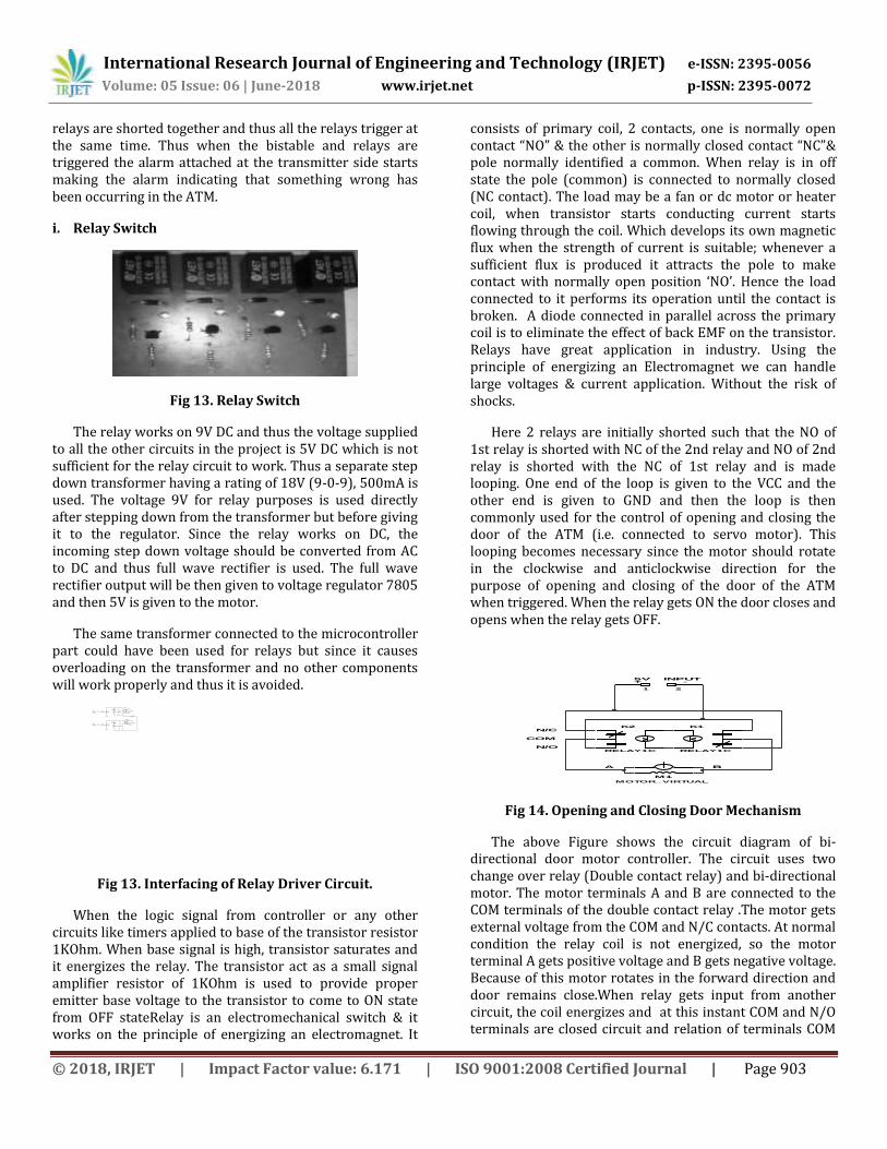
h. Bistable Circuit
Fig 12. Bistable Circuit
A monostable multivibrator has a single stable state, once in the process it goes to a stable state and will again enter the astable state and thus the shutter door of the ATM will open and easily the thief can escape. Astable multivibrator doesn’t have any stable state and thus the output of this always goes high and low and thus the ATM door shutter keeps opening and closing and thus the culprit can escape. A Bistable multivibrator has 2 stable states i.e. high and low. This is the very purpose of using in the project. Thus when once externally triggered the state of the multivibrator goes high and the door of the ATM gets closed until the Bank manager resets the multivibrator i.e. it comes back to the low state and thus the ATM door opens and the culprit can be handovered to the police.
The bistable multivibrator circuit is built with 555 Timer IC. A trigger switch is connected. This multivibrator circuit is placed into the ATM machine and this the ATM is placed on the trigger switch. If in case the ATM is lifted, the bistable multivibrator is triggered and this in turn is connected to relay and thus the relay gets triggered. All the
International Research Journal of Engineering and Technology (IRJET) e-ISSN: 2395-0056
Volume: 05 Issue: 06 | June-2018 www.irjet.net p-ISSN: 2395-0072
© 2018, IRJET | Impact Factor value: 6.171 | ISO 9001:2008 Certified Journal | Page 903
relays are shorted together and thus all the relays trigger at the same time. Thus when the bistable and relays are triggered the alarm attached at the transmitter side starts making the alarm indicating that something wrong has been occurring in the ATM.
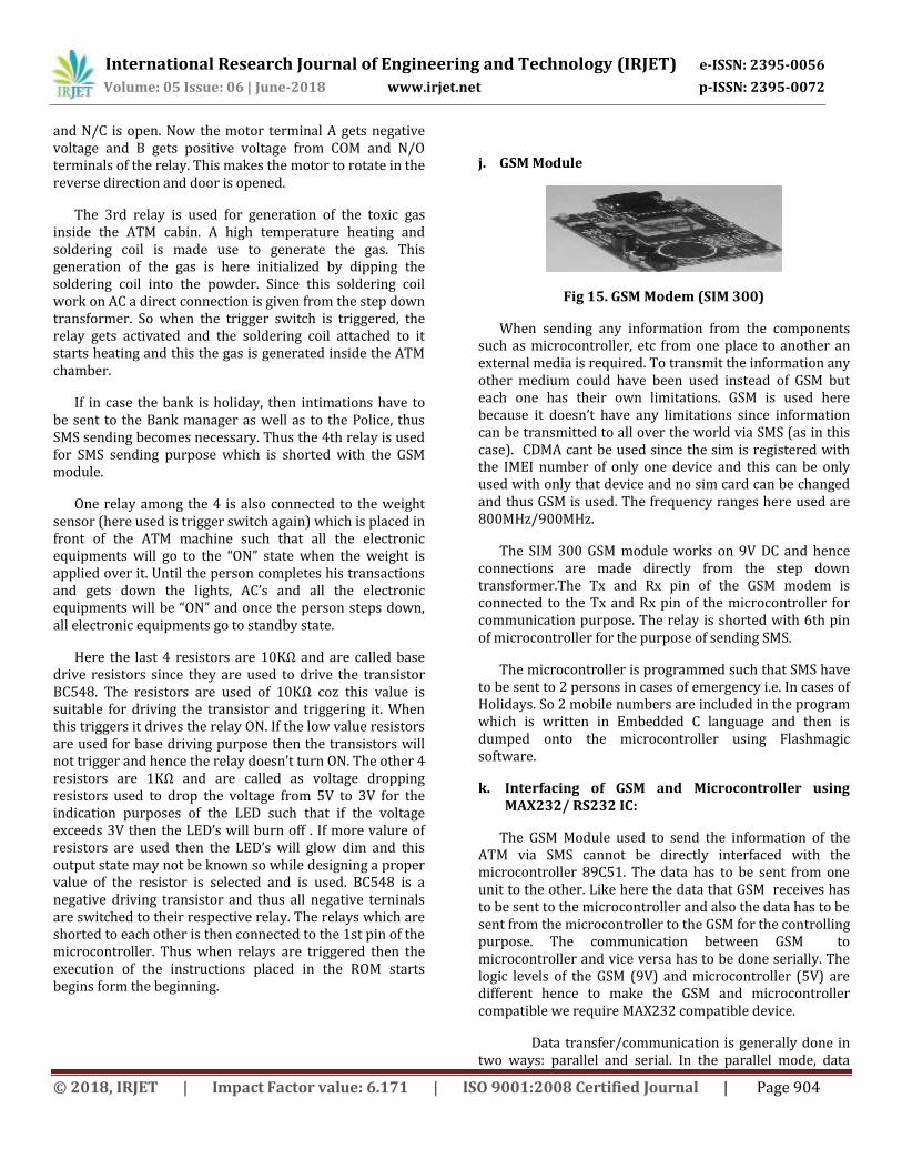
i. Relay Switch
Fig 13. Relay Switch
The relay works on 9V DC and thus the voltage supplied to all the other circuits in the project is 5V DC which is not sufficient for the relay circuit to work. Thus a separate step down transformer having a rating of 18V (9-0-9), 500mA is used. The voltage 9V for relay purposes is used directly after stepping down from the transformer but before giving it to the regulator. Since the relay works on DC, the incoming step down voltage should be converted from AC to DC and thus full wave rectifier is used. The full wave rectifier output will be then given to voltage regulator 7805 and then 5V is given to the motor.
The same transformer connected to the microcontroller part could have been used for relays but since it causes overloading on the transformer and no other components will work properly and thus it is avoided.
220ohm
1kohm
1kohm
220ohm
Q2
BC548
RELAY1C
6V
D1
IN4007
D2
IN4007
LED1
LED2
VCC
Q1
BC548
IO1
IO2
FROM
MC PORTS
FROM
MC PORTS
NC
COMMON
NO
RELAY1C
6VNO1
COMMON1
NC1
Fig 13. Interfacing of Relay Driver Circuit.
When the logic signal from controller or any other circuits like timers applied to base of the transistor resistor 1KOhm. When base signal is high, transistor saturates and it energizes the relay. The transistor act as a small signal amplifier resistor of 1KOhm is used to provide proper emitter base voltage to the transistor to come to ON state from OFF stateRelay is an electromechanical switch & it works on the principle of energizing an electromagnet. It
consists of primary coil, 2 contacts, one is normally open contact “NO” & the other is normally closed contact “NC”& pole normally identified a common. When relay is in off state the pole (common) is connected to normally closed (NC contact). The load may be a fan or dc motor or heater coil, when transistor starts conducting current starts flowing through the coil. Which develops its own magnetic flux when the strength of current is suitable; whenever a sufficient flux is produced it attracts the pole to make contact with normally open position ‘NO’. Hence the load connected to it performs its operation until the contact is broken. A diode connected in parallel across the primary coil is to eliminate the effect of back EMF on the transistor. Relays have great application in industry. Using the principle of energizing an Electromagnet we can handle large voltages & current application. Without the risk of shocks.
Here 2 relays are initially shorted such that the NO of 1st relay is shorted with NC of the 2nd relay and NO of 2nd relay is shorted with the NC of 1st relay and is made looping. One end of the loop is given to the VCC and the other end is given to GND and then the loop is then commonly used for the control of opening and closing the door of the ATM (i.e. connected to servo motor). This looping becomes necessary since the motor should rotate in the clockwise and anticlockwise direction for the purpose of opening and closing of the door of the ATM when triggered. When the relay gets ON the door closes and opens when the relay gets OFF.
M1
MOTOR_VIRTUAL
K1
RELAY1C
K2
RELAY1C
21
5V INPUT
N/C
COM
N/O
+-
-
A B
Fig 14. Opening and Closing Door Mechanism
The above Figure shows the circuit diagram of bi-directional door motor controller. The circuit uses two change over relay (Double contact relay) and bi-directional motor. The motor terminals A and B are connected to the COM terminals of the double contact relay .The motor gets external voltage from the COM and N/C contacts. At normal condition the relay coil is not energized, so the motor terminal A gets positive voltage and B gets negative voltage. Because of this motor rotates in the forward direction and door remains close.When relay gets input from another circuit, the coil energizes and at this instant COM and N/O terminals are closed circuit and relation of terminals COM
International Research Journal of Engineering and Technology (IRJET) e-ISSN: 2395-0056
Volume: 05 Issue: 06 | June-2018 www.irjet.net p-ISSN: 2395-0072
© 2018, IRJET | Impact Factor value: 6.171 | ISO 9001:2008 Certified Journal | Page 904
and N/C is open. Now the motor terminal A gets negative voltage and B gets positive voltage from COM and N/O terminals of the relay. This makes the motor to rotate in the reverse direction and door is opened.
The 3rd relay is used for generation of the toxic gas inside the ATM cabin. A high temperature heating and soldering coil is made use to generate the gas. This generation of the gas is here initialized by dipping the soldering coil into the powder. Since this soldering coil work on AC a direct connection is given from the step down transformer. So when the trigger switch is triggered, the relay gets activated and the soldering coil attached to it starts heating and this the gas is generated inside the ATM chamber.
If in case the bank is holiday, then intimations have to be sent to the Bank manager as well as to the Police, thus SMS sending becomes necessary. Thus the 4th relay is used for SMS sending purpose which is shorted with the GSM module.
One relay among the 4 is also connected to the weight sensor (here used is trigger switch again) which is placed in front of the ATM machine such that all the electronic equipments will go to the “ON” state when the weight is applied over it. Until the person completes his transactions and gets down the lights, AC’s and all the electronic equipments will be “ON” and once the person steps down, all electronic equipments go to standby state.
Here the last 4 resistors are 10KΩ and are called base drive resistors since they are used to drive the transistor BC548. The resistors are used of 10KΩ coz this value is suitable for driving the transistor and triggering it. When this triggers it drives the relay ON. If the low value resistors are used for base driving purpose then the transistors will not trigger and hence the relay doesn’t turn ON. The other 4 resistors are 1KΩ and are called as voltage dropping resistors used to drop the voltage from 5V to 3V for the indication purposes of the LED such that if the voltage exceeds 3V then the LED’s will burn off . If more valure of resistors are used then the LED’s will glow dim and this output state may not be known so while designing a proper value of the resistor is selected and is used. BC548 is a negative driving transistor and thus all negative terninals are switched to their respective relay. The relays which are shorted to each other is then connected to the 1st pin of the microcontroller. Thus when relays are triggered then the execution of the instructions placed in the ROM starts begins form the beginning.
j. GSM Module
Fig 15. GSM Modem (SIM 300)
When sending any information from the components such as microcontroller, etc from one place to another an external media is required. To transmit the information any other medium could have been used instead of GSM but each one has their own limitations. GSM is used here because it doesn’t have any limitations since information can be transmitted to all over the world via SMS (as in this case). CDMA cant be used since the sim is registered with the IMEI number of only one device and this can be only used with only that device and no sim card can be changed and thus GSM is used. The frequency ranges here used are 800MHz/900MHz.
The SIM 300 GSM module works on 9V DC and hence connections are made directly from the step down transformer.The Tx and Rx pin of the GSM modem is connected to the Tx and Rx pin of the microcontroller for communication purpose. The relay is shorted with 6th pin of microcontroller for the purpose of sending SMS.
The microcontroller is programmed such that SMS have to be sent to 2 persons in cases of emergency i.e. In cases of Holidays. So 2 mobile numbers are included in the program which is written in Embedded C language and then is dumped onto the microcontroller using Flashmagic software.
k. Interfacing of GSM and Microcontroller using MAX232/ RS232 IC:
The GSM Module used to send the information of the ATM via SMS cannot be directly interfaced with the microcontroller 89C51. The data has to be sent from one unit to the other. Like here the data that GSM receives has to be sent to the microcontroller and also the data has to be sent from the microcontroller to the GSM for the controlling purpose. The communication between GSM to microcontroller and vice versa has to be done serially. The logic levels of the GSM (9V) and microcontroller (5V) are different hence to make the GSM and microcontroller compatible we require MAX232 compatible device.
Data transfer/communication is generally done in two ways: parallel and serial. In the parallel mode, data

International Research Journal of Engineering and Technology (IRJET) e-ISSN: 2395-0056
Volume: 05 Issue: 06 | June-2018 www.irjet.net p-ISSN: 2395-0072
© 2018, IRJET | Impact Factor value: 6.171 | ISO 9001:2008 Certified Journal | Page 905
transfer is fast and uses more number of lines. This mode is good for short range data transfer. Serial communication on the other hand, uses only one or two data lines to transfer data and is generally used for long distance communication. In serial communication the data is sent as one bit at a time. This article describes the interfacing of 89C51 microcontroller with a GSM via serial port, RS232.
MAX-232 version of serial I/O standard, which is most widely used in PCs, GSM and several devices. In MAX232, high and low bits are represented by flowing voltage ranges. Therefore, while connecting a GSM to microcontroller system, a voltage converter is required. This converter converts the microcontroller output level to the GSM voltage levels, and vice versa. IC MAX232 also known as line driver is very commonly used for this purpose. The simplest connection between a GSM and microcontroller requires a minimum of three pins, RxD (receiver, pin2), TxD (transmitter, pin3) and ground (pin5) of the serial port of GSM.
MAX232 has two sets of line drivers for transferring and receiving data. The line drivers used for transmission are called T1 and T2, where as the line drivers for receiver are designated as R1 and R2.
Fig 16. RS232 Connectivity
SIM 300 is used as a GSM module. An important parameter considered while interfacing serial port is the Baud rate which is the speed at which data is transmitted serially. It is defined as number of bits transmitted or received per second. It is generally expressed in bps (bits per second). AT89C51 microcontroller can be set to transfer and receive serial data at different baud rates using software instructions. The MAX232 IC is used to convert the TTL/CMOS logic levels to RS232 logic levels during serial communication of microcontrollers with GSM. The controller operates at TTL logic level (0-5V) whereas the serial communication with GSM works at 9V. This makes it difficult to establish a direct link between them to communicate with each other, hence max232 IC works as voltage level converter for both the GSM and microcontroller. The intermediate link is provided through MAX232. It is a dual driver/receiver that includes a capacitive voltage generator to supply RS232 voltage levels from a single 5V supply. Each receiver converts GSM inputs
to 5V TTL/CMOS levels. The drivers (T1 & T2), also called transmitters, convert the TTL/CMOS input level into RS232 level. The transmitters take input from controllers serial. Transmission pins and sends the output to GSM receiver. The receivers, on the other hand, take input from transmission pin of serial port and give serial output to microcontroller’s receiver pin. MAX232 needs four external capacitors whose value ranges from 1µF to 22µF.
l. Transmitter Module
Fig 17. Transmitter module (ST-TX01-ASK)
The transmitter module here is placed on the ATM cabin side so as whatever damage that is occuring in the ATM needs to be intimated to the bank and to the police station.
Simultaneously when the relay is triggered, the
transmitter module is activated and thus the information is encoded and is then transmitted through the transmitter. Prior to the sending of the information, whatever the damage has been happened is detected and the location of the ATM with what name it is loaded in the microcontroller is encoded with the help of the Encoder.
Fig 18. Encoder interfaced with Transmitter Module
The encoders of this type are capable of encoding 12bits, consisting of N address bits and 12-N data bits. The HT12E has 8 address bits and 4 data bits. The data that is set on these data lines is sent serially along with the bits set on the address lines. The address bits are sent in prior to the data bits. The data as well as the address is transmitted in four successions. The data consists of differing lengths of positive going pulses for ‘1’ and ‘0’.The pulse width for ‘0’ is twice the pulse width of ‘0’.The frequency of these pulses may lie in between 1.5KHz to 7KHz, depending on the oscillator frequency. This encoder can encode upto 8 “data information” or in other words,
International Research Journal of Engineering and Technology (IRJET) e-ISSN: 2395-0056
Volume: 05 Issue: 06 | June-2018 www.irjet.net p-ISSN: 2395-0072
© 2018, IRJET | Impact Factor value: 6.171 | ISO 9001:2008 Certified Journal | Page 906
this encoder can encode 8 different situations occurring in the same ATM and send the information. Bt here only a single information is loaded “ATM BREAK” in the microcontroller program. This encoder is connected to the ASK Transmitter chip (ST-TX01-ASK) which then transmits the information to the receiver chip at the bank side.
The ST-TX01-ASK is an ASK Hybrid transmitter
module, designed by the Saw Resonator. Its operating frequency is 315/ 433 MHz. It uses the digital modulation (ASK) scheme; Here during the transmission of a binary ‘0’, the carrier wave is fully suppressed i.e. completely OFF, and during the transmission of ‘1’ the carrier wave is ON. Since it operates in the radio frequency range (above 300 MHz), it is known as RF-Transmitter. O/p Power is 4-12 dB. Operating Voltage is 3-6 V and Data rate is 1K-3K bps.
Fig 19. Encoder along with transmitter module
There are 4 LED’s on the transmitter side. These Light Emitting Diodes (LED’s) are numbered as 1,2,4,8 in binary digits accordingly. These LED’s indicate whether which information is being transmitted from the transmitter to the receiver. The four 1KΩ resistors are called as Voltage Dropping resistors whose function is to drop the voltage from 5V to 3V DC because the LED’s work on 3V. If high voltage occurs then the LED’s will burn off and thus again needs to be replaced. The other 2 10KΩ resistors are called as pull-up resistors whose function is to limit the voltage to the transmitter module. 5.2. Receiver Side
Figure 20. Receiver module
a. Receiver Module (ST RX01-ASK) Situated in the system at the BANK side. The receiver
used is the ST-RX-01-ASK module, which is analogous to
the transmitter ST-TX-01-ASK along with decoder HT-12D. The ST- RX01-ASK is an ASK Super heterodyne receiver module with PLL synthesizer and crystal oscillator, which is used as a low-cost ASK/OOK receiver module. The RX01-ASK is a low power RF Receiver module that was developed for wireless data communication devices. Its operating frequency 433MHz, with an intermediate frequency of 10.7KHz. The module ST-RX-01-ASK has eight pins. This receiver receives the information and then demodulates it and then gives it to the decoder for decoding the information
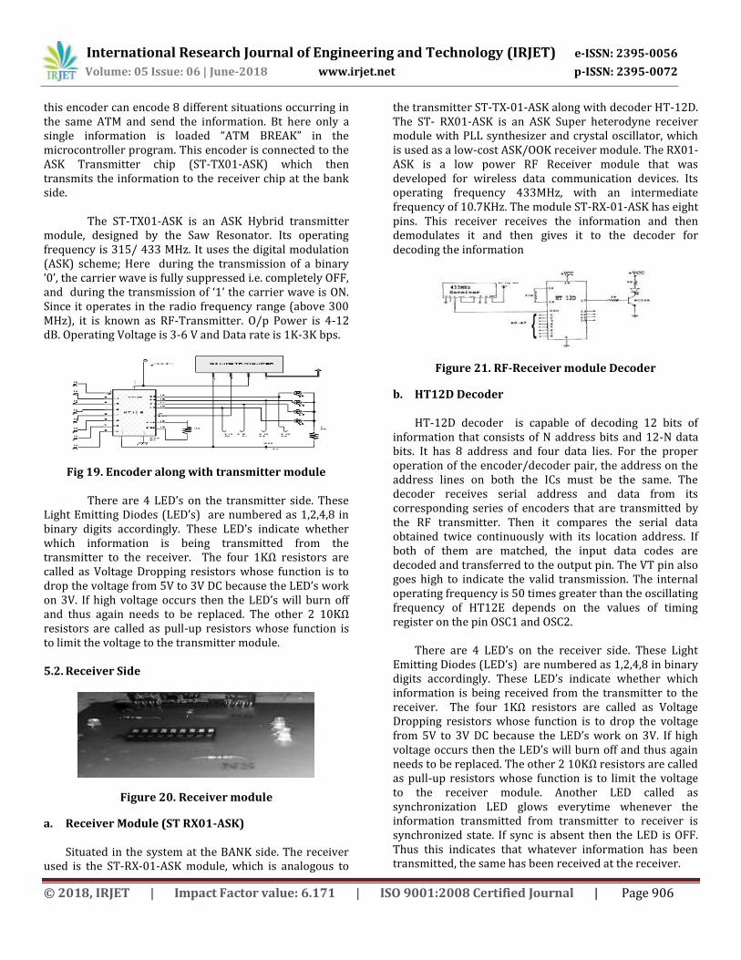
Figure 21. RF-Receiver module Decoder
b. HT12D Decoder HT-12D decoder is capable of decoding 12 bits of
information that consists of N address bits and 12-N data bits. It has 8 address and four data lies. For the proper operation of the encoder/decoder pair, the address on the address lines on both the ICs must be the same. The decoder receives serial address and data from its corresponding series of encoders that are transmitted by the RF transmitter. Then it compares the serial data obtained twice continuously with its location address. If both of them are matched, the input data codes are decoded and transferred to the output pin. The VT pin also goes high to indicate the valid transmission. The internal operating frequency is 50 times greater than the oscillating frequency of HT12E depends on the values of timing register on the pin OSC1 and OSC2.
There are 4 LED’s on the receiver side. These Light Emitting Diodes (LED’s) are numbered as 1,2,4,8 in binary digits accordingly. These LED’s indicate whether which information is being received from the transmitter to the receiver. The four 1KΩ resistors are called as Voltage Dropping resistors whose function is to drop the voltage from 5V to 3V DC because the LED’s work on 3V. If high voltage occurs then the LED’s will burn off and thus again needs to be replaced. The other 2 10KΩ resistors are called as pull-up resistors whose function is to limit the voltage to the receiver module. Another LED called as synchronization LED glows everytime whenever the information transmitted from transmitter to receiver is synchronized state. If sync is absent then the LED is OFF. Thus this indicates that whatever information has been transmitted, the same has been received at the receiver.
International Research Journal of Engineering and Technology (IRJET) e-ISSN: 2395-0056
Volume: 05 Issue: 06 | June-2018 www.irjet.net p-ISSN: 2395-0072
© 2018, IRJET | Impact Factor value: 6.171 | ISO 9001:2008 Certified Journal | Page 907
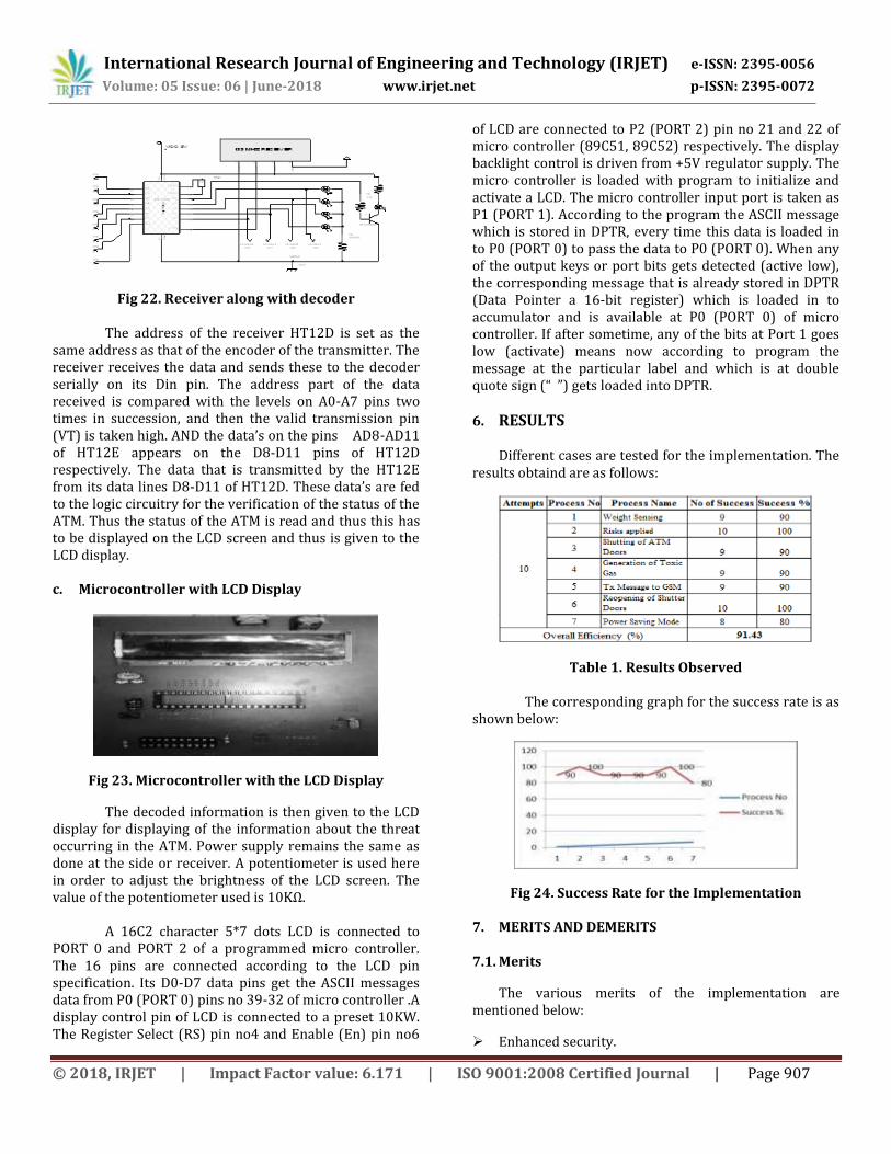
Fig 22. Receiver along with decoder
The address of the receiver HT12D is set as the same address as that of the encoder of the transmitter. The receiver receives the data and sends these to the decoder serially on its Din pin. The address part of the data received is compared with the levels on A0-A7 pins two times in succession, and then the valid transmission pin (VT) is taken high. AND the data’s on the pins AD8-AD11 of HT12E appears on the D8-D11 pins of HT12D respectively. The data that is transmitted by the HT12E from its data lines D8-D11 of HT12D. These data’s are fed to the logic circuitry for the verification of the status of the ATM. Thus the status of the ATM is read and thus this has to be displayed on the LCD screen and thus is given to the LCD display. c. Microcontroller with LCD Display
Fig 23. Microcontroller with the LCD Display
The decoded information is then given to the LCD display for displaying of the information about the threat occurring in the ATM. Power supply remains the same as done at the side or receiver. A potentiometer is used here in order to adjust the brightness of the LCD screen. The value of the potentiometer used is 10KΩ.
A 16C2 character 5*7 dots LCD is connected to PORT 0 and PORT 2 of a programmed micro controller. The 16 pins are connected according to the LCD pin specification. Its D0-D7 data pins get the ASCII messages data from P0 (PORT 0) pins no 39-32 of micro controller .A display control pin of LCD is connected to a preset 10KW. The Register Select (RS) pin no4 and Enable (En) pin no6
of LCD are connected to P2 (PORT 2) pin no 21 and 22 of micro controller (89C51, 89C52) respectively. The display backlight control is driven from +5V regulator supply. The micro controller is loaded with program to initialize and activate a LCD. The micro controller input port is taken as P1 (PORT 1). According to the program the ASCII message which is stored in DPTR, every time this data is loaded in to P0 (PORT 0) to pass the data to P0 (PORT 0). When any of the output keys or port bits gets detected (active low), the corresponding message that is already stored in DPTR (Data Pointer a 16-bit register) which is loaded in to accumulator and is available at P0 (PORT 0) of micro controller. If after sometime, any of the bits at Port 1 goes low (activate) means now according to program the message at the particular label and which is at double quote sign (“ ”) gets loaded into DPTR.
6. RESULTS Different cases are tested for the implementation. The
results obtaind are as follows:
Table 1. Results Observed The corresponding graph for the success rate is as
shown below:
Fig 24. Success Rate for the Implementation
7. MERITS AND DEMERITS
7.1. Merits
The various merits of the implementation are mentioned below:
Enhanced security.

International Research Journal of Engineering and Technology (IRJET) e-ISSN: 2395-0056
Volume: 05 Issue: 06 | June-2018 www.irjet.net p-ISSN: 2395-0072
© 2018, IRJET | Impact Factor value: 6.171 | ISO 9001:2008 Certified Journal | Page 908
No risk of the thief and robbery. Exact time and location is identified. No need of security guard. Person is identified and imprisoned.
7.2. Demerits
Along with some merits, there are some demerits that are as mentioned below:
Failure of sensor result in the failure of whole security system.
An exact amount of toxic gas should be released so as to only unconscious the thief, else excess amount may kill the thief.
Electricity is always necessary as power failure leads to failure of whole system.
8. CONCLUSION
At present there are various techniques which are being successfully used for security of ATM Machine. An example is using CCTV camera for successfully recording the video footage of all the transactions activity in the ATM but such simple security methods weren’t enough to provide much security. Thus GSM technology intervened.
The information related to the attack or the threat occurring in the ATM is initially sensed and simultaneously the information is encoded and sent off to the receiver using radio frequency signals. These radio frequency signals have wide range of transmission and thus can be placed at any distance. Door is closed and thus the thief can’t escape. Toxic gas generation unit is activated at the same time, the thief becomes unconscious thus the internal activities that again occur in the ATM is prohibited. Power saving mode saves a lot of power. Alarm generation unit alerts the surrounding people about the irregular activity within the ATM. GSM provide a pathway for the delivery of the messages to 2 different people in case of holidays. The bistable can finally be only reset by the head of the bank. Thus the security features were enhanced largely for the stability and reliability of owner recognition. The method of protecting the ATM machine can be said as a method having no disadvantages. The whole system was build on the technology of embedded system which makes the system more safe, reliable and easy to use.
9. FUTURE SCOPE The future scopes of the implemented applications
may be extended as follows:
Finger Print Technology can be included for security and valid authorization.
Retina Scan and Heart Beat Scanning Technology can also be included.
Charging of the battery and storing it after converting it to DC which is given directly from the supply.
GPS Module can be added to know the exact location of the ATM since there are many ATM centres in a particular place.
Gas Chambers can be implemented in real time wherein to allow excess gas out it can be done using 2 DC motors wherein they work alternatively depending upon the timers set.
Pressure and vibration sensors can also be added to sense the pressures and vibrations.
References:
[1] Armenian Luther George Simjian(. 17 April in 1920) “Automatic Teller Machine The history of computing Project”. Thocp.net.
[2] John Adrian Shepherd-Barron, British inventor(1960), “Development the cash machine Automated Teller Machine or ATM ”.
[3] B. M. Nelligani, N. V. U. Reddy and N. Awasti, "Smart ATM security system using FPR, GSM, GPS," 2016 International Conference on Inventive Computation Technologies (ICICT), Coimbatore, 2016.
[4] Roli, B., Priti S. and Punam B. (2011): Minutiae Extraction from Fingerprint Images. International Journal of Computer Science Issues, vol.8, Issue 5, No3. ISSN(online):1694
[5] Brunner, A., Decressin, J. and Kudela, B. (2004): Germany’s Three-Pillar Banking System – Cross Country Perspectives in Europe, Occasional Paper, International Monetary Fund, Washington DC.
[6] The Ankit Anil Agarwal, Saurabh Kumar, Sultania, Gourav Jaiswal, Prateek Jain(2011), “RFID Based ATM security is developed” .
[7] Cynthia B. (2000). The measurement of white-collar crime using Uniform Crime Reporting (UCR) Data. S department of Justice, Federal Bureau of Investigation, New York.
[8] Madu, C.N., & Madu, A.A. (2002). Dimensions of e-quality. International Journal of Quality & Reliability Management, 19(3), 246-58.
[9] Implementation of ATM security system using GSM and MEMS”, Swpnali Gunjal, Nikita Shete, Poonam
International Research Journal of Engineering and Technology (IRJET) e-ISSN: 2395-0056
Volume: 05 Issue: 06 | June-2018 www.irjet.net p-ISSN: 2395-0072
© 2018, IRJET | Impact Factor value: 6.171 | ISO 9001:2008 Certified Journal | Page 909
Shete, Surekha Sarode, International Journal of Research in Advent Technology (IJRAT), 2017.
[10] P.K. Amurthy and M.S. Redddy(2012), “Implementation of ATM Security by Using Fingerprint recognition and GSM”, International Journal of Electronics Communication and Computer Engineering vol.3, no. 1, pp. 83-86,.
[11] ATM Security using GSM and Fingerprint with Authorized Permission for Transaction, T.N.S.Pallavadhar, V.Srinivas, International Journal of Emerging Engineering Research and Technology Volume 3, Issue 11, November 2015.
[12] ATM Authentication with Enhance Security Using GSM, Prof. Y. R. Risodkar , Ashwini. B. Pawar, Sampada. N. Chavanke, Ashwini. S. Pawar
[13] Sakr, Sharif. "ARM co-founder John Biggs". Engadget. Retrieved December 23, 2011. "[...] the ARM7- TDMI was licensed by Texas Instruments and designed into the Nokia 6110, which was the first ARM powered GSM phone." electricmotors.machinedesign.com.
[14] Kim, Bo-Ra, “Domestic ATM status and meanings”, Payment and Settlement, and IT, Vol. 44, pp. 76, 2011.


![MIMO Systems:[1] - JNNCE ECE Manjunath](https://static.fdocuments.net/doc/165x107/6288709032ca1b3a4f614c18/mimo-systems1-jnnce-ece-manjunath.jpg)