ATM-ASDE System Cassiopeia-5i2msystems.com/documents/sim_atc_description_v2.1.pdf · ATM-ASDE...
12
ATM-ASDE System Cassiopeia-5 Casseopeia-5 consists of the following componeents: Multi-Sensor Data Processor (MSDP) Controller Working Position (CWP) Maintenance Workstation The ASDE is able to accept the following input data: Sensor data in ASTERIX Cat010 format from ◦ Surface movement radar (SMR) ◦ Multi-lateration system (MLAT) ◦ ADS-B/Mode S Ground Receiver Station ◦ Magnetic loop sensor system System data ◦ Track and FlightPlan data from Approach ATM system (in ASTERIX format) ◦ Meteo information (METAR/TAF reports) Video surveillance data The system is able to produce the following output data: A-SMGCS surveillance and alerting information (in ASTERIX Cat011 format) Lighting system control commands Surveillance video server commands The Multi-Sensor Data Processor performs: Data fusion from different surveillance sensor systems Receiving data from Approach RDPS and FDPS Image extraction, track data post-processing (if necessary) Conflict detection and safety alerting Data recording and replay Output data preparation Report generation The general specification of the required SMR is: X-Band Solid-state technology Data output in Eurocontrol ASTERIX format Data/Signal processing – clutter, multipath rejection, rain effects mitigation Multichannel transceiver
Transcript of ATM-ASDE System Cassiopeia-5i2msystems.com/documents/sim_atc_description_v2.1.pdf · ATM-ASDE...

ATM-ASDE System Cassiopeia-5
Casseopeia-5 consists of the following componeents:
Multi-Sensor Data Processor (MSDP)
Controller Working Position (CWP)
Maintenance Workstation The ASDE is able to accept the following input data:
Sensor data in ASTERIX Cat010 format from
◦ Surface movement radar (SMR)
◦ Multi-lateration system (MLAT)
◦ ADS-B/Mode S Ground Receiver Station
◦ Magnetic loop sensor system
System data
◦ Track and FlightPlan data from Approach ATM system (in ASTERIX format)
◦ Meteo information (METAR/TAF reports)
Video surveillance data
The system is able to produce the following output data:
A-SMGCS surveillance and alerting information (in ASTERIX Cat011 format)
Lighting system control commands
Surveillance video server commands The Multi-Sensor Data Processor performs:
Data fusion from different surveillance sensor systems
Receiving data from Approach RDPS and FDPS
Image extraction, track data post-processing (if necessary)
Conflict detection and safety alerting
Data recording and replay
Output data preparation
Report generation The general specification of the required SMR is:
X-Band Solid-state technology
Data output in Eurocontrol ASTERIX format
Data/Signal processing – clutter, multipath rejection, rain effects mitigation
Multichannel transceiver

LAN
CWP
... ...
SMR equipment
ASTERIXoutput
Multi-sensorData Processor
ADS-B/Mode SGround Station
MLAT ServerStation
ApproachATM system
Video SurveillanceSystem
MeteoSystem
ASTERIXRDPS & FDPSdata
Surveillance Data FusionDetection and Safety AlertsRecording and replayOutput data preparation
Magnetic loopsensor system
ASTERIXoutput
Maintanenceworkstation
ASTERIXoutput
METARTAF
LightingSystem
ControlCommands &state reports
Videodata
System diagram
*Blocks filled with green represent Casseopeia-5 hardware

The Human-Machine Interface of the CWP component provides:
Ground View Display
Airspace View Display
ILS View Display (optional)
Runway View Display (optional)
Lighting equipment control display
Video Surveillance Display (single or multiple) Airport map features
detailed map (runway limits and thresholds, taxiways, holding positions, stop bars, runway exits, intersections, parking positions, gates)
range scale change (zoom in/out)
off-centering
polar grid
adding user-defined zones
adding user-defined text
getting map context information
configurable color and transparency scheme (switchable presets)
graphical layer management Track displaying features
track marks according to current status and priority
configurable labels (identification, velocity, etc)
label offsetting (automatic and manual)
speed vector
history dots
track filtering (by altitude, zone, priority, status, inbound/outbound)
ASDE controller functions
system flight plan and airport schedule browsing
arrival sequencing
departure sequencing
distance and bearing tool (between moving and static objects)
taxi route assignment with automatic proposal
indication of the taxi route to be followed
target trajectory prediction
short-term conflict detection and alerting (STCA)
◦ between ground moving objects
◦ between ground moving objects and static obstacles
◦ between aircraft in flight
medium-term conflict detection and alerting (MTCD)
◦ between ground moving objects
◦ between aircraft in flight
conflict resolution advisory tool
ground area penetration detection and alerting
◦ runway/taxiway/apron incursion and excursion
◦ entering prohibited/restricted/sensitive areas
airspace proximity (APW) detection and alerting
route deviation detection and alerting
speed limit and wrong direction detection and alerting
runway occupancy automated setting and indication (landing, take-off, maintenance work, runway closed)
surveillance video integration
lighting system control
weather information
coordination tools with Approach controllers
The Maintenance workstation provides a special HMI to monitor and control the state of the system and its components.

Current state of implementation
It is proposed to build the required ASDE system with use of extended versions of currently available simulation platform components. Below is the description of the available components.
1.1. Controller Working Position (CWP). The CWP is designed to provide the operator with two-display interface consisting of:
Main Surveillance Display
Lighting equipment control display The whole HMI is a multi-window application with window transparency and roll-up/roll-down functions
supported. 1.1.1. The Main Surveillance Display comprises two views showing current traffic situation:
Ground 2D View - shows the airport map including runways, taxiways, apron area with the ground traffic (aircraft and service vehicles);
Airspace 2D View shows the airspace structure (including CTA, TMA. RA/PA, FIR boundaries, NAVAIDs, routes, runway axes) and all aircraft in flight (en-route, approach, landing/taking-off)
The following graphical map features are implemented for the both views:
cursor-selectable tracks
map off-centering
range scale selection, zoom in/out tool
distance and bearing measurement tool (between 2 points on the map)
polar or latitude-longitude grid displaying (enabled for the Airspace view only)
map object context information
graphical layer hiding/showing (every map object type has its own separate layer)
color and transparency scheme can be configured per layer
map object data is imported from standard ARINC-424 files Additional available panels and windows:
main tool panel
time and status window (date/time, QNH, runway in use, controller role, controller id)
map configuration window (scale, visual layer management)
map context information window
virtual pilot flight command window (for simulation purposes only)
standard phraseology reference window (for training purposes only)
virtual binocular control window (is used to adjust orientation and zoom of the binocular view frame displayed on a simulator projection screen as well as to capture the target aircraft to be followed)
weather report window The following screenshots show the current look of the CWP graphical interface

Picture 1 – Main Surveillance Display: Ground and Airspace views
Picture 2 – Main Surveillance Display: auxiliary information windows
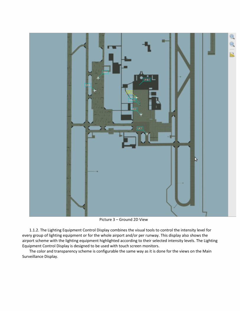
Picture 3 – Ground 2D View
1.1.2. The Lighting Equipment Control Display combines the visual tools to control the intensity level for
every group of lighting equipment or for the whole airport and/or per runway. This display also shows the airport scheme with the lighting equipment highlighted according to their selected intensity levels. The Lighting Equipment Control Display is designed to be used with touch screen monitors.
The color and transparency scheme is configurable the same way as it is done for the views on the Main Surveillance Display.

Picture 4 – Lighting Equipment Control Display
Visual System:
image generation servers
projection system (tower view + virtual binocular) System core components:
internal network exchange subsystem
flight dynamics server
airspace data server
weather server
terrain server
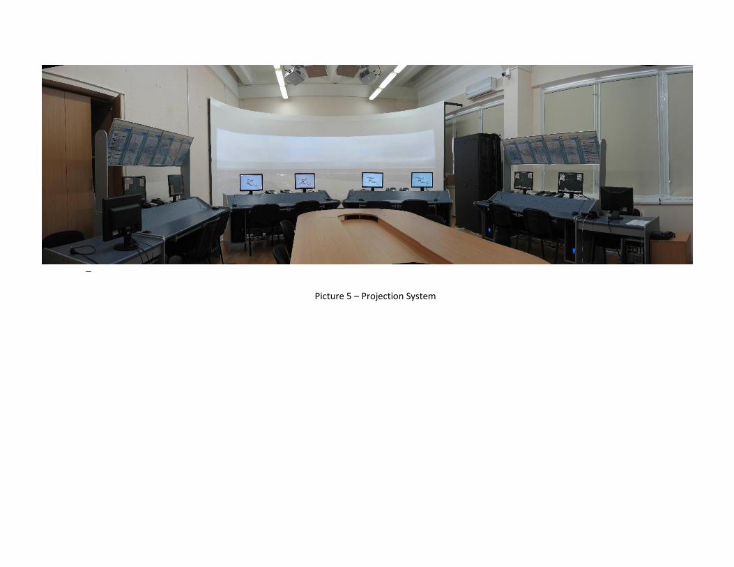
Picture 5 – Projection System

Picture 6 – Projection System

2. Additional Functionality
Function 1 CWP graphical interface features Interactive map: 1.1 Displaying of additional aerodrome markings: stop bars, taxiway center lines and intersections,
parking areas, apron restricted areas, terminal gates 1.2 History dots of target tracks 1.3 Configurable track labels (the text field contents and their order) 1.4 Automatic track label offsetting and label dragging functions 1.5 Track marks indicating aircraft weight category or dimensions 1.6 Track filtering (altitude, zone, priority, status, inbound/outbound) 1.7 Track status/priority assignment and color highlighting 1.8 Distance and bearing measurement tool snapping to moving objects 1.9 Predefined taxi routes proposal 1.10 Manual taxi route assignment (using pointer or typing taxiway IDs) 1.11 Indication of the assigned taxi route to be followed Alerting and trajectory: 1.12 Aircraft/vehicle trajectory prediction (check-point times) 1.13 Short-term conflict visual alerting (STCA): 1.1.1 between ground moving objects 1.1.2 between ground moving objects and static obstacles 1.1.3 between aircraft in flight 1.14 Medium-term conflict visual alerting (MTCD): 1.1.1 between ground moving objects 1.1.2 between aircraft in flight 1.15 Airspace proximity warning (for aircraft in air) 1.16 Conflict resolution advisory tool 1.17 Ground area penetration alerting (runway/taxiway/apron incursion and excursion alerts,
entering prohibited/restricted/sensitive areas, crossing stop bars) 1.18 Route deviation alerting 1.19 Speed limit and wrong direction alerting for air and ground traffic (aircraft and vehicles) 1.20 Runway occupancy setting and indication (landing, take-off, maintenance work, runway closed) User-defined customization 1.21 User text-labeling (adding text on the map) 1.22 User-defined zones (adding zones on the map) 1.23 Switchable predefined color schemes (day/night) 1.24 User-defined hotkeys support 1.25 Keeping user-defined window layout 1.26 Keeping user-defined GUI and system settings Additional windows/views: 1.25 Runway view 1.26 ILS view 1.27 Flight strip window 1.28 System flight plan window 1.29 Airport flight schedule window 1.30 Arrival sequence window 1.31 Departure sequence window 1.32 Surveillance video integration (separate window or display) 1.33 System status window
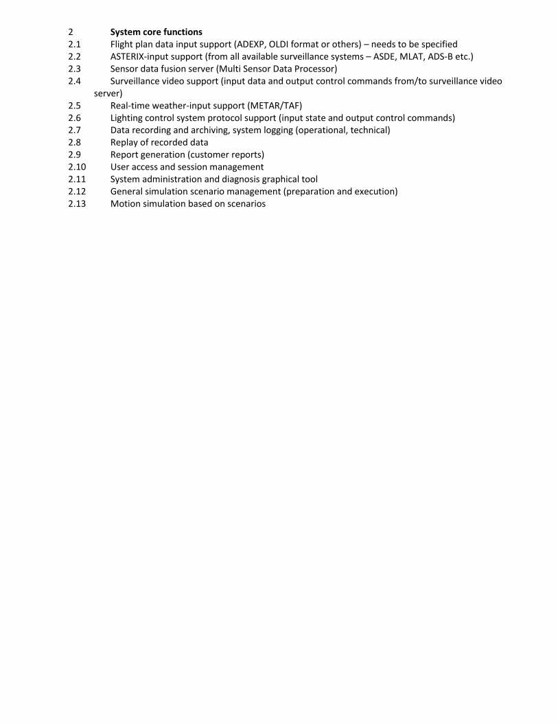
2 System core functions 2.1 Flight plan data input support (ADEXP, OLDI format or others) – needs to be specified 2.2 ASTERIX-input support (from all available surveillance systems – ASDE, MLAT, ADS-B etc.) 2.3 Sensor data fusion server (Multi Sensor Data Processor) 2.4 Surveillance video support (input data and output control commands from/to surveillance video
server) 2.5 Real-time weather-input support (METAR/TAF) 2.6 Lighting control system protocol support (input state and output control commands) 2.7 Data recording and archiving, system logging (operational, technical) 2.8 Replay of recorded data 2.9 Report generation (customer reports) 2.10 User access and session management 2.11 System administration and diagnosis graphical tool 2.12 General simulation scenario management (preparation and execution) 2.13 Motion simulation based on scenarios