ATM 401 Sampling Asphalt Materials · 2020-05-14 · Alaska Test Methods Manual 401-3 Effective May...
154
Alaska Test Methods Manual 401-1 Effective May 30, 2020 ATM 401 Sampling Asphalt Materials The following guidelines for the use of WAQTC FOP for AASHTO R 66 by the State of Alaska DOT&PF. 1. When obtaining samples from HMA plants, sample only from the line between the storage tank and the mixing plant while the plant is in operation. 2. Sample containers for elastomer modified asphaltic cements shall conform to requirements under containers/asphalt binders. 3. When sampling emulsified asphalt, use 1 gallon wide mouth plastic containers. 4. When material is sampled by other than DOT&PF personnel or their agent(s), the sampling must be witnessed and possession of the sample transferred immediately to DOT&PF personnel or their agent(s). 5. Sampling locations are described in AASHTO R 66. They include the spigot at HMA plant, from barrels, from the delivery truck or the distributor spray bar.
Transcript of ATM 401 Sampling Asphalt Materials · 2020-05-14 · Alaska Test Methods Manual 401-3 Effective May...

Alaska Test Methods Manual 401-1 Effective May 30, 2020
ATM 401 Sampling Asphalt Materials
The following guidelines for the use of WAQTC FOP for AASHTO R 66 by the State of Alaska DOT&PF.
1. When obtaining samples from HMA plants, sample only from the line between the storage tank and the mixing plant while the plant is in operation.
2. Sample containers for elastomer modified asphaltic cements shall conform to requirements under containers/asphalt binders.
3. When sampling emulsified asphalt, use 1 gallon wide mouth plastic containers.
4. When material is sampled by other than DOT&PF personnel or their agent(s), the sampling must be witnessed and possession of the sample transferred immediately to DOT&PF personnel or their agent(s).
5. Sampling locations are described in AASHTO R 66. They include the spigot at HMA plant, from barrels, from the delivery truck or the distributor spray bar.

Effective May 30, 2020 401-2 Alaska Test Methods Manual
This page intentionally left blank.

Alaska Test Methods Manual 401-3 Effective May 30, 2020
SAMPLING ASPHALT MATERIALS FOP FOR AASHTO R 66
Scope This procedure covers obtaining samples of liquid asphalt materials in accordance with AASHTO R 66-16. Sampling of solid and semi-solid asphalt materials – included in AASHTO R 66 – is not covered here.
Agencies may be more specific on exactly who samples, where to sample, and what type of sampling device to use.
Warning: Always use appropriate safety equipment and precautions for hot liquids.
Terminology
• Asphalt binder: Asphalt cement or modified asphalt cement that binds the aggregate particles into a dense mass.
• Asphalt emulsion: A mixture of asphalt binder and water.
• Cutback asphalt: Asphalt binder that has been modified by blending with a chemical solvent.
Procedure 1. Coordinate sampling with contractor or supplier.
2. Allow a minimum of 4 L (1 gal) to flow before obtaining a sample(s).
3. Obtain samples of:
• Asphalt binder from the line between the storage tank and the mixing plant while the plant is in operation, or from the delivery truck.
• Cutback and emulsified asphalt from distributor spray bar or application device or from the delivery truck before it is pumped into the distributor. Sample emulsified asphalt at delivery or before dilution.
Containers Sample containers must be new, and the inside may not be washed or rinsed. The outside may be wiped with a clean, dry cloth.
All samples shall be put in 1 L (1 qt) containers and properly identified on the outside of the container with contract number, date sampled, data sheet number, brand and grade of material, and sample number. Include lot and sublot numbers when appropriate.
• Emulsified asphalt: Use wide-mouth plastic jars with screw caps. Protect the samples from freezing since water is a part of the emulsion. The sample container should be completely filled to minimize a skin formation on the sample.
• Asphalt binder and cutbacks: Use metal cans
Note: The sample container shall not be submerged in solvent, nor shall it be wiped with a solvent saturated cloth. If cleaning is necessary, use a clean dry cloth.
Report
• On forms approved by the agency
• Sample ID

Effective May 30, 2020 401-4 Alaska Test Methods Manual
• Date
• Time
• Location
• Quantity represented

Alaska Test Methods Manual 402-1 Effective May 30, 2020
ATM 402 Sampling of Asphalt Mixtures
Following are guidelines for the use of WAQTC FOP for AASHTO R 97 (derived from ASTM D979) by the State of Alaska DOT&PF.
1. ATM 403 contains additional sampling methods.
2. When sampling asphalt mixture from a mat after compaction, sample in accordance with ATM 413 “Standard Practice for Sampling Asphalt Mixtures after Compaction (Obtaining Cores).”

Effective May 30, 2020 402-2 Alaska Test Methods Manual
This page intentionally left blank.

Alaska Test Methods Manual 402-3 Effective May 30, 2020
SAMPLING OF ASPHALT MIXTURES FOP FOR AASHTO R 97
Scope This procedure covers the sampling of asphalt mixtures from plants, haul units, and roadways in accordance with AASHTO R 97. Sampling is as important as testing, use care to obtain a representative sample and to avoid segregation and contamination of the material during sampling.
Apparatus
• Shovel or Metal Scoops, or Other Equipment: square-head metal shovels at least 125 mm (5.5 in.) wide.
• Sample containers: such as cardboard boxes, metal cans, stainless steel bowls, or other agency-approved containers
• Sampling plate: thick metal plate, minimum 8 gauge, sized to accommodate sample requirements, with a wire attached to one corner long enough to reach from the center of the paver to the outside of the farthest auger extension. A minimum of one hole 6 mm (0.25 in.) in diameter must be provided in a corner of the plate.
• Cookie cutter sampling device: formed steel angle with two 100 mm by 150 mm by 9 mm (4 in. by 6 in. by 3/8 in.) handles, sized to accommodate sample requirements. Minimum 50 mm (2 in.) smaller than the sampling plate when used together.
Example: Sampling plate 380 mm (15 in.) square and a cookie cutter sampling device 330 mm (13 in.) square.
• Mechanical sampling device: a permanently attached device that allows a sample receptacle to pass perpendicularly through the entire stream of material or diverts the entire stream of material into the container by manual, hydraulic, or pneumatic operation.
• Release agent: a non-stick product that prevents the asphalt mixture from sticking to the apparatus and does not contain solvents or petroleum-based products that could affect asphalt binder properties.
Sample Size Sample size depends on the test methods specified by the agency for acceptance. Check agency requirement for the size required.
Procedure
General
• Select sample locations using a random or stratified random sampling procedure, as specified by the agency. The material shall be tested to determine variations. The supplier/contractor shall provide equipment for safe and appropriate sampling, including sampling devices on plants when required.
• Ensure the container(s) and sampling equipment are clean and dry before sampling.
• For dense graded mixture samples use cardboard boxes, stainless steel bowls or other agency-approved containers.
• For hot open graded mixture samples use stainless steel bowls. Do not put open graded mixture samples in boxes until they have cooled to the point that asphalt binder will not migrate from the aggregate.

Effective May 30, 2020 402-4 Alaska Test Methods Manual
Attached Sampling Devices
These are normally permanently attached devices that allow a sample container to pass perpendicularly through the entire stream of material. Operation may be hydraulic, pneumatic, or manual and allows the sample container to pass through the stream twice, once in each direction, without overfilling. A sampling device may also divert the entire stream into a sampling receptacle.
1. Lightly coat the container attached to the sampling device with an agency-approved release agent or preheat it, or both, to approximately the same discharge temperature of the mix.
2. Pass the container twice through the material perpendicularly without overfilling the container.
3. Transfer the asphalt mixture to an agency-approved container without loss of material.
4. Repeat until proper sample size has been obtained.
5. Combine the increments to form a single sample.
Conveyor Belts
1. Avoid sampling at the beginning or end of an asphalt mixture production run due to the potential for segregation.
2. Stop the belt containing asphalt mixture.
3. Set the sampling template into the asphalt mixture on the belt, avoiding intrusion by adjacent material.
4. Remove the asphalt mixture from inside the template, including all fines, and place in a sample container.
5. Repeat, obtaining equal size increments, until proper sample size has been obtained.
6. Combine the increments to form a single sample.
Haul Units
1. Visually divide the haul unit into approximately four equal quadrants.
2. Identify one sampling location in each quadrant.
3. Dig down and remove approximately 0.3 m (1 ft.) of material to avoid surface segregation. Obtain each increment from below this level.
4. Combine the increments to form a sample of the required size.
Paver Auger
1. Obtain samples from the end of the auger using a square head shovel.
2. Place the shovel in front of the auger extension, with the shovel blade flat upon the surface to be paved over.
3. Allow the front face of the auger stream to cover the shovel with asphalt mixture, remove the shovel before the auger reaches it by lifting as vertically as possible.
4. Place asphalt mixture in a sample container.
5. Repeat until proper sample size has been obtained.
6. Combine the increments to form a sample of the required size.
Note 1: First full shovel of material may be discarded to preheat and ‘butter’ the shovel.
Windrow

Alaska Test Methods Manual 402-5 Effective May 30, 2020
1. Obtain samples from the windrow of a transport unit. Avoid the beginning or the end of the windrow section.
2. Visually divide the windrow into approximately three equal sections.
3. Remove approximately 0.3 m (1 ft) from the top of each section.
4. Fully insert the shovel into the flat surface as vertically as possible, exclude the underlying material, roll back the shovel and lift the material slowly out of the windrow to avoid material rolling off the shovel.
5. Place in a sample container.
6. Repeat, obtaining equal size increments, in each of the remaining thirds.
7. Combine the increments to form a sample of the required size.
Roadway Before Compaction
There are two conditions that will be encountered when sampling asphalt mixtures from the roadway before compaction. The two conditions are:
• Laying asphalt mixture on grade or untreated base material requires Method 1.
• Laying asphalt mixture on existing asphalt or laying a second lift of asphalt mixture requires Method 2.
SAFETY Sampling is performed behind the paving machine and in front of the breakdown roller. For safety, the roller must remain at least 3 m (10 ft.) behind the sampling operation until the sample has been taken and the hole filled with loose asphalt mixture.
Method 1 requires a plate to be placed in the roadway in front of the paving operation and therefore there is always concern with moving, operating equipment. It is safest to stop the paving train while a plate is installed in front of the paver. When this is not possible the following safety rules must be followed.
1. The plate placing operation must be at least 3 m (10 ft.) in front of the paver or pickup device. The technician placing the plate must have eye contact and communication with the paving machine operator. If eye contact cannot be maintained at all time, a third person must be present to provide communication between the operator and the technician.
2. No technician is to be between the asphalt supply trucks and the paving machine. The exception to this rule is if the supply truck is moving forward creating a windrow, in which case the technician must be at least 3 m (10 ft.) behind the truck.
If at any time the Engineer feels that the sampling technique is creating an unsafe condition, the operation is to be halted until it is made safe or the paving operation will be stopped while the plate is being placed.
Method 1 - Obtaining a Sample on Untreated Base (Plate Method)
1. Following the safety rules detailed above, the technician is to:

Effective May 30, 2020 402-6 Alaska Test Methods Manual
a. Smooth out a location in front of the paver at least 0.5 m (2 ft.) inside the edge of the mat.
b. Lay the plate down diagonally with the direction of travel, keeping it flat and tight to the base with the lead corner facing the paving machine.
Note 2: The plate may be secured by driving a nail through the hole in the lead corner of the plate.
2. Pull the wire, attached to the outside corner of the plate, taut past the edge of the asphalt mixture mat and secure it. Let the paving operation pass over the plate and wire.
3. Using the exposed end of the wire, pull the wire up through the fresh asphalt mixture to locate the corner of the plate.
a. Plate only:
i. Using a small square head shovel or scoop, or both, remove the full depth of the asphalt mixture from the plate. Take care to prevent sloughing of adjacent material.
ii. Place asphalt mixture, including any material adhering to the plate and scoop or shovel in a sample container.
b. “Cookie Cutter”:
i. Place the “cookie cutter” sample device, just inside the end of the wire; align the cutter over the plate. Press “cookie cutter” device down through the asphalt mixture to the plate.
ii. Using a small square tipped shovel or scoop, or both, carefully remove all the asphalt mixture from inside of the cutter and place in a sample container.
iii. Remove the sample cutter and the plate from the roadway. The hole made from the sampling must be filled by the contractor with loose asphalt mixture.
Method 2 - Obtaining a Sample on Asphalt Surface (Non-plate Method)
1. After the paving machine has passed the sampling point, immediately place the “cookie cutter” sampling device on the location to be sampled.
2. Push the cutter down through the asphalt mixture until it is flat against the underlying asphalt mat.
3. Using a small square tipped shovel or scoop, or both, carefully remove all the asphalt mixture from inside of the cutter and place in a sample container.
4. Remove the cutter from the roadway. The hole made from the sampling must be filled by the contractor with loose asphalt mixture.
Stockpiles
Remove at least 0.1 m (4 in.) from the surface before sampling; mixtures in a stockpile may develop an oxidized crust.
Method 1 – Loader
1. Direct the loader operator to enter the stockpile with the bucket at least 0.3 m (1 ft) above ground level without contaminating the stockpile.
2. Obtain a full loader bucket of the asphalt mixture; tilt the bucket back and up.
3. Form a small sampling pile at the base of the stockpile by gently rolling the asphalt mixture out of the bucket with the bucket just high enough to permit free-flow of the mixture. Repeat as necessary.
4. Create a flat surface by having the loader "back-drag" the small pile.

Alaska Test Methods Manual 402-7 Effective May 30, 2020
5. Obtain approximately equal increments from at least three randomly selected locations on the flat surface at least 0.3 m (1 ft) from the edge.
6. Fully insert the shovel, exclude the underlying material, roll back the shovel and lift the asphalt mixture slowly out of the pile to avoid mixture rolling off the shovel.
7. Combine the increments to form a sample.
Method 2 – Stockpile Face
1. Create horizontal surfaces with vertical faces in the top, middle, and bottom third of the stockpile with a shovel or a loader if one is available.
2. Shove a flat board against the vertical face behind the sampling location to prevent sloughing of asphalt mixture. Discard the sloughed mixture to create the horizontal surface.
3. Obtain the sample from the horizontal surface as close as possible to the intersection of the horizontal and vertical faces.
4. Obtain at least one sample increment of equal size from each of the top, middle, and bottom thirds of the pile.
5. Combine the increments to form a single sample.
Identification and Shipping 1. Identify sample containers as required by the agency.
2. Ship samples in containers that will prevent loss, contamination, or damage.
Report
• On forms approved by the agency
• Sample ID
• Date
• Time
• Location
• Quantity represented

Effective May 30, 2020 402-8 Alaska Test Methods Manual
This page intentionally left blank.

Alaska Test Methods Manual 403-1 Effective May 30, 2020
ATM 403 Sampling Hot Mix Asphalt
1. Scope This method describes procedures used for sampling Hot Mix Asphalt (HMA).
2. Significance and Use This method provides procedures for sampling HMA in the field. Sampling is equally as important as the testing, and the sampler shall use every precaution to obtain samples that will yield an acceptable estimate of the nature and conditions of the materials for which they represent. Care shall be taken in sampling to avoid segregation of the material being sampled, and to prevent contamination by dust or other foreign matter.
If material is sampled by other than DOT&PF personnel or their agent(s), the sampling must be witnessed and possession of the sample transferred immediately to DOT&PF personnel or their agent(s).
The method of sampling must be approved at the project level.
3. Equipment
• Flat scoop with vertical sides or a square point shovel.
• Plate with small lip (approximately ½”) and of sufficient size and rigidity to accommodate required sample. Plate to have wire(s) attached to allow the plate to be located and removed from the mat after paver travels past it.
• Approved sample containers including new cardboard boxes, clean metal buckets, cans or bowls.
• Miscellaneous tools, scraper, scoop, gloves, etc.
4. Sampling from the Auger (Not Allowed on FHWA Projects) 1. Obtain samples from the accessible portion of the auger, using a square point shovel.
2. Place the shovel in front of the auger, with the blade flat upon the surface to be paved.
3. Allow the front face of the HMA coming off the auger to cover the shovel. Remove the shovel before the auger reaches the shovel by lifting it upward as vertically as possible being careful not to lose material.
4. Repeat the procedure at least three times, but as many times as necessary to obtain a sample of the required size.
5. Place the sample in an approved container for transport to Lab.
5. Lipped Plate Sampling 1. When using a pickup machine:
a. Stop the paver and pickup machine.
b. Place plate(s) underneath the pickup machine, midway between and just behind the rear tires and right in front of the paver.
2. When using dump trucks:
a. Stop the paver after the truck is attached to the paver.
b. Place plate(s) at the midpoint of the axis of the paver and behind the truck tires.
Note 1: When placing plate(s), avoid influence from truck tires, pickup machine tires, and paver tracks or tires.

Effective May 30, 2020 403-2 Alaska Test Methods Manual
3. Run an attached wire perpendicular to the direction of the paver, beyond the farthest auger extension and/or the ski.
4. Hold the wire to the ground with your foot.
5. Allow the paving operation to resume.
6. When the paver has passed over the plate position, pull up on the wire to locate the plate. Remove the plate(s) laden with mix from the HMA mat by lifting vertically being careful not to disturb the mix at the edge of the plate.
7. Place the entire sample in an approved container(s) for transport to the Lab
Note 2: Make sure to hold the wire down on the ground so the ski will not snag it.
6. Windrow Sampling 1. Sample from the windrow created by a single truck. Visually divide the windrow length into three equal
sections.
2. Sample from the middle of each of the three sections as shown in the diagrams below. Remove and discard the top 12 inches of material. Remove one increment for each required sample, from each location by digging vertically down with a square point shovel.
3. Place each sample increment from the first location into separate approved containers. Move to the second location and add one sample increment to each container. Move to third location and repeat sampling.
4. Place the acceptance sample containers in an insulated box for transport to the Lab.
Windrow Longitudinal Section
Windrow Cross Section

Alaska Test Methods Manual 404-1 Effective May 30, 2020
ATM 404 Reducing Samples of Asphalt Mixtures to Testing Size
Following are guidelines for the use of WAQTC FOP for AASHTO R 47 by the State of Alaska DOT&PF.
1. The incremental method may be done without sheeting.
2. When project specifications allow the use of a mechanical splitter, care must be taken to ensure the splitter is level.
3. Aerosol vegetable cooking spray is approved as a release agent.
4. Under Procedure Mechanical Splitter Type B (Riffle) insert image:

Effective May 30, 2020 404-2 Alaska Test Methods Manual
This page intentionally left blank.

Alaska Test Methods Manual 404-3 Effective May 30, 2020
REDUCING SAMPLES OF ASPHALT MIXTURES TO TESTING SIZE FOP FOR AASHTO R 47
Scope This procedure covers sample reduction of asphalt mixtures to testing size in accordance with AASHTO R 47-19. The reduced portion is to be representative of the original sample.
Apparatus
• Thermostatically controlled oven capable of maintaining a temperature of at least 110°C (230°F) or high enough to heat the material to a pliable condition for splitting.
• Non-contact temperature measuring device.
• Metal spatulas, trowels, metal straightedges, or drywall taping knives, or a combination thereof; for removing asphalt mixture samples from the quartering device, cleaning surfaces used for splitting, etc.
• Square-tipped, flat-bottom scoop, shovel or trowel for mixing asphalt mixture before quartering.
• Miscellaneous equipment including hot plate, non-asbestos heat-resistant gloves or mittens, pans, buckets, and cans.
• Sheeting: Non-stick heavy paper or other material as approved by the agency.
• Agency-approved release agent, free of solvent or petroleum-based material that could affect asphalt binder.
• Mechanical Splitter Type B (Riffle): having a minimum of eight equal-width chutes discharging alternately to each side with a minimum chute width of at least 50 percent larger than the largest particle size. A hopper or straight-edged pan with a width equal to or slightly smaller than the assembly of chutes in the riffle splitter to permit uniform discharge of the asphalt mixture through the chutes without segregation or loss of material. Sample receptacles of sufficient width and capacity to receive the reduced portions of asphalt mixture from the splitter without loss of material.
• Quartering Template: formed in the shape of a cross with equal length sides at right angles to each other. Template shall be manufactured of metal that will withstand heat and use without deforming. The sides of the quartering template should be sized so that the length exceeds the diameter of the flattened cone of asphalt mixture by an amount allowing complete separation of the quartered sample. Height of the sides must exceed the thickness of the flattened cone of asphalt mixture.
• Non-stick mixing surface that is hard, heat-resistant, clean, level, and large enough to permit asphalt mixture samples to be mixed without contamination or loss of material.
Sampling Obtain samples according to the FOP for AASHTO R 97.
Sample Preparation The sample must be warm enough to separate. If not, warm in an oven until it is sufficiently soft to mix and separate easily. Do not exceed either the temperature or time limits specified in the test method(s) to be performed.
Selection of Procedure (Method) Refer to agency requirements when determining the appropriate method(s) of sample reduction. In general, the selection of a particular method to reduce a sample depends on the initial size of the sample vs. the size of the sample needed for the specific test to be performed. It is recommended that, for large amounts of material, the

Effective May 30, 2020 404-4 Alaska Test Methods Manual
initial reduction be performed using a mechanical splitter. This decreases the time needed for reduction and minimizes temperature loss. Further reduction of the remaining asphalt mixture may be performed by a combination of the following methods, as approved by the agency. The methods for reduction are:
• Mechanical Splitter Type B (Riffle) Method
• Quartering Method
− Full Quartering
− By Apex
• Incremental Method
Procedure When heating of the equipment is desired, it shall be heated to a temperature not to exceed the maximum mixing temperature of the job mix formula (JMF).
Mechanical Splitter Type B (Riffle) Method 1. Clean the splitter and apply a light coating of approved release agent to the surfaces that will come in contact
with asphalt mixture (hopper or straight-edged pan, chutes, receptacles).
2. Place two empty receptacles under the splitter.
3. Carefully empty the asphalt mixture from the agency-approved container(s) into the hopper or straight-edged pan without loss of material. Uniformly distribute from side to side of the hopper or pan.
4. Discharge the asphalt mixture at a uniform rate, allowing it to flow freely through the chutes.
5. Any asphalt mixture that is retained on the surface of the splitter shall be removed and placed into the appropriate receptacle.
6. Reduce the remaining asphalt mixture as needed by this method or a combination of the following methods as approved by the agency.
7. Using one of the two receptacles containing asphalt mixture, repeat the reduction process until the asphalt mixture contained in one of the two receptacles is the appropriate size for the required test.
8. After each split, remember to clean the splitter hopper and chute surfaces if needed.
9. Retain and properly identify the remaining unused asphalt mixture sample for further testing if required by the agency.
Quartering Method 1. If needed, apply a light coating of release agent to quartering template.
2. Dump the sample from the agency approved container(s) into a conical pile on a hard, “non-stick,” clean, level surface where there will be neither a loss of material nor the accidental addition of foreign material. The surface can be made non-stick by the application of an approved asphalt release agent, or sheeting.
3. Mix the material thoroughly by turning the entire sample over a minimum of four times with a flat-bottom scoop; or by alternately lifting each corner of the sheeting and pulling it over the sample diagonally toward the opposite corner, causing the material to be rolled. Create a conical pile by either depositing each scoop or shovelful of the last turning on top of the preceding one or lifting both opposite corners.
4. Flatten the conical pile to a uniform diameter and thickness where the diameter is four to eight times the thickness. Make a visual observation to ensure that the material is homogeneous.

Alaska Test Methods Manual 404-5 Effective May 30, 2020
5. Divide the flattened cone into four equal quarters using the quartering template or straightedges assuring complete separation.
6. Reduce to appropriate sample mass by full quartering or by apex.
Full Quartering
a. Remove diagonally opposite quarters, including all of the fine material, and place in a container to be retained.
b. Remove the quartering template, if used.
c. Combine the remaining quarters.
d. If further reduction is necessary, repeat Quartering Method Steps 3 through 6.
e. Repeat until appropriate sample mass is obtained. The final sample must consist of the two remaining diagonally opposite quarters.
f. Retain and properly identify the remaining unused portion of the asphalt mixture sample for further testing if required by the agency.
Reducing by Apex
a. Using a straightedge, slice through a quarter of the asphalt mixture from the center point to the outer edge of the quarter.
b. Pull or drag the material from the quarter with two straight edges or hold one edge of the straightedge in contact with quartering device.
c. Remove an equal portion from the diagonally opposite quarter and combine these increments to create the appropriate sample mass.
d. Continue using the apex method with the unused portion of the asphalt mixture until samples have been obtained for all required tests.
e. Retain and properly identify the remaining unused portion of the asphalt mixture sample for further testing if required by the agency.
Incremental Method 1. Cover a hard, clean, level surface with sheeting. This surface shall be large enough that there will be neither a
loss of material nor the accidental addition of foreign material.
2. Place the sample from the agency approved container(s) into a conical pile on that surface.
3. Mix the material thoroughly by turning the entire sample over a minimum of four times:
a. Use a flat-bottom scoop; or
b. Alternately lift each corner of the sheeting and pull it over the sample diagonally toward the opposite corner, causing the material to be rolled.
4. Create a conical pile by either depositing each scoop or shovelful of the last turning on top of the preceding one or lifting both opposite corners.
5. Grasp the sheeting and roll the conical pile into a cylinder (loaf), then flatten the top. Make a visual observation to determine that the material is homogenous.
6. Remove one quarter of the length of the loaf and place in a container to be saved; by either:

Effective May 30, 2020 404-6 Alaska Test Methods Manual
a. Pull sheeting over edge of counter and drop material into container.
b. Use a straightedge at least as wide as the full loaf to slice off material and place into container.
7. Obtain an appropriate sample mass for the test to be performed; by either:
a. Pull sheeting over edge of counter and drop cross sections of the material into container until proper sample mass has been obtained.
b. Use a straightedge at least as wide as the full loaf to slice off cross sections of the material until proper sample mass has been obtained and place into container.
Note 1: When reducing the sample to test size it is advisable to take several small increments, determining the mass each time until the proper minimum size is achieved. Unless the sample size is grossly in excess of the minimum or exceeds the maximum test size, use the sample as reduced for the test.
8. Repeat Step 7 until all the samples for testing have been obtained or until final quarter of the original loaf is reached.
9. Retain and properly identify the remaining unused portion of the asphalt mixture sample for further testing if required by the agency.

Alaska Test Methods Manual 405-1 Effective May 30, 2020
ATM 405 Asphalt Cement Content of Hot Mix Asphalt by the Nuclear Method
1. Scope This method covers the quantitative determination of the asphalt cement content of Hot Mix Asphalt by testing a sample with a device that utilizes neutron thermalization techniques. This is an adaptation of AASHTO T 287. Job mix design (JMD) calibration, cross calibration of master and field gauges and calibration transfer are included.
2. Referenced Documents
• WAQTC Standards:
o FOP for AASHTO T 2 (ASTM D75) , Sampling of Aggregates
o FOP for AASHTO T 168 (ASTM D979), Sampling Bituminous Paving Mixtures
o FOP for AASHTO R47, Reducing Samples of Hot Mix Asphalt to Testing Size
o FOP for AASHTO T 329, Moisture Content of Bituminous Mixes by Oven
• Other Documents:
o Manufacturer’s instruction manual.
3. Significance and Use This method can be used for rapidly determining the asphalt content of HMA. Testing can be completed in a matter of minutes so that adjustments, if necessary, can be made in the asphalt metering system with a limited amount of mix production. The procedure is useful in the determination of asphalt content only, as it does not provide extracted aggregate for the gradation analysis.
4. Apparatus
• Nuclear asphalt content gauge system consisting of:
o Neutron source: an encapsulated and sealed radioactive source
o Thermal neutron detectors
o Read-out instrument displaying, at a minimum, percent asphalt cement
o Two or more stainless steel sample pans conforming to gauge requirements
• Sample containers with lids or other methods of closing to prevent contamination and of sufficient size to hold the entire sample. The containers should be able to withstand the reheating of the mix to mixing temperature.
• Sample quartering apparatus conforming to requirements of the WAQTC FOP for AASHTO R 47.
• Balance or scale: capable of determining mass to 15 kg, readable to 1 g and conforming to AASHTO M 231.
• Drying oven, of either of the following types, capable of handling the volume and sample size expected for the project:
• Forced air, ventilated or convection oven capable of maintaining a temperature of 177 ±3°C (350 ±5°F)

Effective May 30, 2020 405-2 Alaska Test Methods Manual
• Leveling plate: Flat, rigid plate of metal with a minimum thickness of 10 mm (⅜ in) and slightly larger than the sample pans
• Thermometer with a temperature range of 10-300°C (50-500°F)
• Assorted pans, spoons, spatulas, and mixing bowls
• Radioactive materials information and calibration packet containing:
o Daily Background Count Log
o Leak Test Certificate
o Shippers Declaration for Dangerous Goods
o Procedure Memo for Storing, Transporting and Handling Nuclear Testing Equipment
o Other radioactive materials documentation as required by local regulatory requirements
5. Precautions 1. The equipment shall be so constructed as to be licensable in accordance with applicable health and safety
regulations.
2. Equipment operators shall wear an approved form of radiation dosimetry (i.e., film badges, thermo luminescent dosimeter, etc.) capable of monitoring the occupational radiation exposure.
3. Since nuclear equipment measures the total amount of hydrogen in the sample, this procedure is sensitive to changes in moisture content. It must be remembered that both asphalt cement and water contain hydrogen.
4. Keep any other source of neutron radiation at least 10 m (30 ft.) from the equipment. Do not place the equipment where large amounts of hydrogenous material may be moved during the calibration or testing procedures (for example, water or plastic materials).
5. All personnel shall be kept at least 1 m (3 ft.) away from the gauge during testing.
6. Standardization 1. Obtain and record a 16 minute background count, in accordance with manufacturer’s procedure, each day
prior to taking test measurements or whenever the gauge has been moved or the conditions within 1 m (3 ft) of the gauge have changed. The measurement time for the background count is the same as that used for test measurements.
2. If the background count has not changed by more than 2 percent from the previous background count, then the apparatus shall be considered stable and acceptable for use. If the gauge has been moved or if the surrounding conditions have changed, additional background counts must be obtained until the 2 percent standard is met.
7. Calibration 1. This method is sensitive to the type of aggregate, percentage and source of asphalt cement, and to the
aggregate gradation. Accordingly, a calibration curve must be developed for each mix type. When changes occur, a new calibration should be run. The curve shall be established with 3 points. (See Appendix A)
2. Prior to the start of each test, verify that the activated calibration is correct.

Alaska Test Methods Manual 405-3 Effective May 30, 2020
8. Procedure 1. Determine the mass of a clean gauge sample pan, and use this to determine the sample mass in the pan, or
tare the pan on the scale.
2. Using a hot asphalt concrete mixture sample having a temperature of 121° to 149°C (250° to 300°F) obtained in accordance with WAQTC FOP for AASHTO T 168, and reduced in accordance with WAQTC FOP for AASHTO R 47, fill the sample pan one-half full, evenly distributing the sample in the pan. Level the asphalt concrete mixture with a preheated trowel or spatula, spading as necessary to compact (usually 10 to 15 spades are sufficient), being careful to avoid segregating the mix or driving the fines into the bottom.
3. Fill the remainder of the pan until the mass of the asphalt concrete mixture in the pan is approximately equal to or up to 5 grams above the mass of mix used for the calibration samples. Level the top of the asphalt concrete mixture using a spatula or trowel and spade as necessary to compact (usually 10 to 15 spades are sufficient), avoiding segregation of the mix. Compact the sample into the pan, until it is level with the top of the pan, by standing on the metal plate and rocking/twisting back-and-forth.
4. Verify that the mass of mix is ± 5 g of the calibration mass. Record the mass of the asphalt concrete mixture in the pan.
5. If the gauge does not have temperature compensation capability, measure and record the temperature of the compacted specimen. This temperature must be within ± 5°C (± 9°F) of the calibration test specimen temperature.
6. Place the pan into the gauge. Perform a 16 minute count.
7. Determine and record the uncorrected asphalt cement content to the nearest 0.01 percent by direct readout from the gauge, from the calibration graph, or by the formula supplied by the manufacturer.
8. Using a representative portion of the original sample or a portion of the material removed from the gauge pan, determine the moisture in the mixture in accordance with the WAQTC FOP for AASHTO T 329 and record to the nearest 0.01 percent.
Note 1: When taking the moisture from the gauge pan sample, remove it immediately after completing the oil content test.
9. Calculation 1. Subtract the moisture content from the uncorrected asphalt cement content. Record this as the corrected
asphalt cement content.
10. Report
• Results shall be reported on standard forms approved by the Department.
• Make, model, and serial number of the nuclear asphalt content gauge.
• Date and source of calibration.
• Date of test.
• Name and signature of operator.
• Background count for the day of the test.
• Mix identification.

Effective May 30, 2020 405-4 Alaska Test Methods Manual
• Aggregate type and source(s); Asphalt cement source, type and grade.
• Calibration sample mass and temperature.
• Test sample mass and temperature, if gauge does not have temperature compensation capability
• Gauge reading, including print-out from gauge.
• Asphalt cement content value to the nearest 0.1 %.
• Attach the Nuclear Gauge print out to the report.

Alaska Test Methods Manual 405-5 Effective May 30, 2020
Appendix A ATM 405
1. Gauge Calibration 1. Obtain samples of aggregate in accordance with WAQTC FOP for AASHTO T 2 (ASTM D75).
Approximately 50 kg (110 lb.) total will be required for calibration specimens. Dry the aggregates in accordance with WAQTC FOP for AASHTO T 255/T 265, separate into sieve sizes determined by the JMD.
2. Blend the aggregate together at the proper proportion to match the job mix formula following steps 3 and 4.
3. Calculate the required cumulative mass for each specified sieve using the following formula:
where: X = Required cumulative batch mass for each specified sieve P = Percent passing for each specified sieve according to the job mix formula T = Initial total aggregate mass
4. Correct for aggregate dust as follows.
a. Prepare a wash gradation sample from the mass calculated in Step 4.
b. Perform a washed gradation following WAQTC FOP for AASHTO T 27/T 11.
c. Compute the corrected batch mass for each specified sieve for the calibration points using the following formula:
where: Zn = Adjusted cumulative batch mass for sieve size n. X = Pre-wash cumulative batch mass for each specified sieve. Y = Post-wash cumulative batch mass for each specified sieve.
5. Obtain samples of bituminous materials in accordance with WAQTC FOP for AASHTO T 40. Approximately 4 L (1 gal) will be required.
6. Calculate the mass of asphalt cement for each calibration point as follows:
B = E x Pbm
where: B = mass of asphalt cement to the nearest 0.1 g E = mass of mix Pbm = percent asphalt cement content by total mass of mixture, expressed as a decimal.
7. Use the three following asphalt cement contents:
a. Specified minus 1.0 percent
b. Specified (mix design value)
T100
P)(100X ×−
=
YXZ
2
n =

Effective May 30, 2020 405-6 Alaska Test Methods Manual
c. Specified plus 1.0 percent
8. Calculate the mass of aggregate required for each calibration point as follows:
A = E – B
where: A = mass of aggregate to the nearest 0.1 g B = mass of asphalt cement to the nearest 0.1 g E = mass of mix
2. Preparation of Calibration Specimens 1. Heat the prepared aggregate specimens to the mixing temperature range midpoint for the asphalt cement ±
5°C (± 9°F) and hold at that temperature for three hours or to constant mass.
2. Heat the asphalt cement to the mid-point of the mixing temperature range ± 5°C (± 9°F) in a covered container(s). It is best to use the asphalt cement as soon as it reaches mixing temperature. If this is not possible, maintain the asphalt cement at this temperature, rather than cool and reheat it, but do not hold the sample at this temperature for more than 4 hours.
3. All bowls, sample pans, and tools should be heated to the mid-point of the mixing temperature range ± 5°C (± 9°F). An initial or “butter” mix is required to condition the mixing equipment. Mix a minimum of three asphalt concrete specimens to cover the approximate range of the design asphalt content. Mix one at the design asphalt content, one 1.0 percent above, and one 1.0 percent below, use the same grade and type of asphalt as will be used in the asphalt concrete mixture to be tested. Mix 7000-9000g for each specimen.
4. Fill the sample pan one-half full, evenly distributing the sample in the pan. Level the asphalt concrete mixture with a spatula or trowel and spade as necessary to compact, avoiding segregation of the mix. Fill the remainder of the pan until the asphalt concrete mixture is mounded slightly above the top of the pan. Record the weight of the asphalt concrete mixture in the pan. This is the weight that is to be used for all calibration and test samples using this calibration. Level the top of the asphalt concrete mixture using a spatula or trowel and spade as necessary to compact, avoiding segregation of the mix. Use the metal plate to consolidate the asphalt concrete mixture until it is level with the top edge of the pan. All specimens should be compacted at the mid-point of the mixing temperature range ± 5°C (± 9°F) to ensure that the mix will compact properly.
5. Place each calibration pan into the gauge and proceed in accordance with the manufacturer’s instructions for operation of the equipment and the sequence of operations. Count each calibration sample for 16 minutes.
Note 1: Do not forget to perform and record a background count as per the manufacturer’s instructions.
6. For gauges that generate the calibration internally, print out the formula coefficients (“A” Values), the coefficient of fit and the calculated percent difference for each calibration point. The coefficient of fit must be between 0.998 and 1.000 for dense graded mix or 0.995 and 1.000 for open graded mix. Calibration points must have a calculated percent difference of less than 0.09 percent. If either requirement is not met, the calibration must be redone.
7. Store the acceptable calibration in the gauge’s memory, using the job mix formula and the Contract number or an easily recognizable calibration number, according to the manufacturer’s instructions.
8. For gauges other than the Troxler, prepare a calibration curve by plotting the calibration sample gauge readings versus asphalt cement content on linear graph paper, choosing convenient scale factors for gauge readings and asphalt cement content.

Alaska Test Methods Manual 405-7 Effective May 30, 2020
9. Calculate the correlation factor for gauges without internal calculations according to the following formula:
∑
∑
−
−
−=
∧
i ii
i ii
YY
YYnFactorCorrelatio 2
2
1
where:
iY = actual percent asphalt values for each sample ∧
iY = calculated percent asphalt values from curve
iY = mean value of the actual percentages asphalt, and i = number of calibration samples.

Effective May 30, 2020 405-8 Alaska Test Methods Manual
Appendix B ATM 405
1. Cross Calibration (Troxler 3241) 1. Cross calibrating creates a relationship between the field gauge and a master gauge. This allows testing
of production mix with a field gauge without the need to perform physical calibrations. When several gauges are cross calibrated, the mix calibrations may be transferred to each. The master gauge is normally located where the calibration sample pans are fabricated.
2. The central lab shall prepare the cross calibration samples. Prepare six calibration samples, using a locally available specification aggregate, with binder contents between 3 and 8 percent at 1 percent increments or per the gauge manufacturer’s instructions. Mix the samples so that each pan of mix equals the base mass ± 5 g. Run each sample in the master gauge using a 16 minute count in the normal calibration mode. After all samples are run, the gauge will automatically calculate a coefficient of fit. The coefficient of fit must be at least 0.999.
3. Seal each pan to prevent change in hydrogen content and repeat steps 1 and 2. Sealed pans must meet same criteria.
4. Run each of the six sealed calibration samples in the field gauge while in cross calibration mode utilizing a 16 minute count. For each calibration sample, input the information from the master gauge into the field gauge. When the six cross calibration samples have been counted, print out the cross calibration data. The coefficient of fit must be .999 or 1.000. If this requirement is met, the master gauge and the field gauge are cross calibrated.
2. Calibration Transfer When the field gauge has been cross calibrated with the master gauge a calibration transfer can be performed. JMD calibrations can now be transferred to the field gauge, using input data only. This transfer would be in lieu of calibrating the field gauge with a JMD calibration. Follow the manufacturer’s instructions to perform this transfer.

Alaska Test Methods Manual 406-1 Effective May 30, 2020
ATM 406 Determining the Asphalt Binder Content of Hot Mix Asphalt (HMA) by the Ignition Method
Following are guidelines for the use of WAQTC FOP for AASHTO T 308 by the State of Alaska DOT&PF.
1. Delete Step 9 in Correction Factors – Procedure.
2. Unless otherwise specified, Method A (using Method B step 16 calculation) shall be used.
3. Verify oven balance accuracy with standard masses to 0.1 gram tolerance, prior to calibration and testing. Recommend sending 1.00 kilogram standard mass with all field labs.
4. Asphalt binder content shall be calculated with masses determined on an external balance. This applies to all test samples as well as calibration samples.
5. Nominal Maximum size shall be determined by the Job Mix Formula target value gradation.
6. Determine Mf 30 to 60 minutes after removing from oven.
7. Corrected asphalt binder content reported to 0.1 percent.
8. Use of the printed ticket is optional.

Effective May 30, 2020 406-2 Alaska Test Methods Manual
This page intentionally left blank.

Alaska Test Methods Manual 406-3 Effective May 30, 2020
DETERMINING THE ASPHALT BINDER CONTENT OF ASPHALT MIXTURES BY THE IGNITION METHOD FOP FOR AASHTO T 308
Scope This procedure covers the determination of asphalt binder content of asphalt mixtures by ignition of the binder in accordance with AASHTO T 308-18.
Overview The sample is heated in a furnace at 538°C (1000°F) or less; samples may be heated by convection or direct infrared irradiation (IR). The aggregate remaining after burning can be used for sieve analysis using the FOP for AASHTO T 30.
Some agencies allow the use of recycled asphalt mixtures. When using recycled asphalt mixtures, check with the agency for specific correction procedures.
Asphalt binder in the asphalt mixture is ignited in a furnace. Asphalt binder content is calculated as the percentage difference between the initial mass of the asphalt mixture and the mass of the residual aggregate, with the asphalt binder correction factor, and moisture content subtracted. The asphalt binder content is expressed as percent of moisture-free mix mass.
Two methods, A and B, are presented.
Apparatus Note 1: The apparatus must be calibrated for the specific mix design. See “Correction Factors” at the end of this FOP.
The apparatus for the Methods A and B is the same except that the furnace for Method A requires an internal balance.
• Ignition Furnace: A forced-air ignition furnace that heats the specimens by either the convection or direct IR irradiation method. The convection-type furnace must be capable of maintaining the temperature at 538 ± 5°C (1000 ± 9°F).
For Method A, the furnace will be equipped with an internal scale thermally isolated from the furnace chamber and accurate to 0.1 g. The scale shall be capable of determining the mass of a 3500 g sample in addition to the sample baskets. A data collection system will be included so that mass can be automatically determined and displayed during the test. The furnace shall have a built-in computer program to calculate the change in mass of the sample baskets and provide for the input of a correction factor for aggregate loss. The furnace shall provide a printed ticket with the initial specimen mass, specimen mass loss, temperature compensation, correction factor, corrected asphalt binder content, test time, and test temperature. The furnace shall provide an audible alarm and indicator light when the sample mass loss does not exceed 0.01 percent of the total sample mass for three consecutive minutes. Perform lift test according to manufacturer’s instructions weekly during use, if applicable.
Note 2: The furnace shall be designed to permit the operator to change the ending mass loss percentage from 0.01 percent to 0.02 percent.
For both Method A and Method B, the furnace chamber dimensions shall be adequate to accommodate a 3500 g sample. The furnace door shall be equipped so that it cannot be opened during the ignition test. A method for reducing furnace emissions shall be provided and the furnace shall be vented so that no emissions escape into the laboratory. The furnace shall have a fan to pull air through the furnace to expedite the test and to eliminate the escape of smoke into the laboratory.
• Sample Basket Assembly: consisting of sample basket(s), catch pan, and basket guards. Sample basket(s) will be of appropriate size allowing samples to be thinly spread and allowing air to flow through and around

Effective May 30, 2020 406-4 Alaska Test Methods Manual
the sample particles. Sets of two or more baskets shall be nested. A catch pan: of sufficient size to hold the sample basket(s) so that aggregate particles and melting asphalt binder falling through the screen mesh are caught. Basket guards will completely enclose the basket and be made of screen mesh, perforated stainless steel plate, or other suitable material.
• Thermometer, or other temperature measuring device, with a temperature range of 10 -260°C (50-500°F).
• Oven capable of maintaining 110 ±5°C (230 ±9°F).
• Balance or scale: Capacity sufficient for the sample mass and conforming to the requirements of M 231, Class G2.
• Safety equipment: Safety glasses or face shield, high temperature gloves, long sleeved jacket, a heat resistant surface capable of withstanding 650°C (1202°F), a protective cage capable of surrounding the sample baskets during the cooling period, and a particle mask for use during removal of the sample from the basket assembly.
• Miscellaneous equipment: A pan larger than the sample basket(s) for transferring sample after ignition, spatulas, bowls, and wire brushes.
Sampling 1. Obtain samples of asphalt mixture in accordance with the FOP for AASHTO R 97.
2. Reduce asphalt mixture samples in accordance with the FOP for AASHTO R 47.
3. If the mixture is not sufficiently soft to separate with a spatula or trowel, place it in a large flat pan in an oven at 110 ±5°C (230 ±9°F) until soft enough.
4. Test sample size shall conform to the mass requirement shown in Table 1.
Note 3: When the mass of the test specimen exceeds the capacity of the equipment used or for large samples of fine mixes, the test specimen may be divided into suitable increments, tested, and the results appropriately combined through a weighted average for calculation of the asphalt binder content.
Table 1
Nominal Maximum Aggregate Size*
mm (in.)
Minimum
Mass Specimen
g
Maximum
Mass Specimen
g 37.5 (1 ½) 4000 4500
25.0 (1) 3000 3500 19.0 (3/4) 2000 2500 12.5 (1/2) 1500 2000 9.5 (3/8) 1200 1700
4.75 (No. 4) 1200 1700 * One sieve larger than the first sieve to retain more than 10 percent of the material using an agency specified set of sieves based on cumulative percent retained. Where large gaps in specification sieves exist, intermediate sieve(s) may be inserted to determine nominal maximum size.
Procedure – Method A (Internal Balance) 1. For the convection-type furnace, preheat the ignition furnace to 538 ± 5°C (1000 ± 9°F) or to the temperature
determined in the “Correction Factor” section, Step 9 of this method. Manually record the furnace

Alaska Test Methods Manual 406-5 Effective May 30, 2020
temperature (set point) before the initiation of the test if the furnace does not record automatically. For the direct IR irradiation-type furnace, use the same burn profile as used during the correction factor determination.
2. Dry the sample to constant mass, according to the FOP for AASHTO T 329; or determine the moisture content of a companion sample in accordance with the FOP for AASHTO T 329.
3. Determine and record the mass to the nearest 0.1 g of the sample basket assembly.
4. Evenly distribute the sample in the sample basket assembly, taking care to keep the material away from the edges of the basket. Use a spatula or trowel to level the sample.
5. Determine and record the total mass of the sample and sample basket assembly at room temperature to the nearest 0.1 g. Calculate and record the initial mass of the sample (total mass minus the mass of the sample basket assembly) to the nearest 0.1 g. Designate this mass as (Mi).
6. Record the correction factor or input into the furnace controller for the specific asphalt mixture.
7. Input the initial mass of the sample (Mi) into the ignition furnace controller. Verify that the correct mass has been entered.
CAUTION: Operator should wear safety equipment – high temperature gloves, face shield, fire-retardant shop coat – when opening the door to load or unload the sample.
8. Open the chamber door and gently set the sample basket assembly in the furnace. Carefully position the sample basket assembly so it is not in contact with the furnace wall. Close the chamber door and verify that the sample mass displayed on the furnace scale equals the total mass of the sample and sample basket assembly recorded in Step 5 within ±5 g.
Note 4: Furnace temperature will drop below the set point when the door is opened, but will recover when the door is closed and ignition begins. Sample ignition typically increases the temperature well above the set point – relative to sample size and asphalt binder content.
9. Initiate the test by pressing the start button. This will lock the sample chamber and start the combustion blower.
Safety Note: Do not attempt to open the furnace door until the asphalt binder has been completely burned off.
10. Allow the test to continue until the stable light and audible stable indicator indicate that the change in mass does not exceed 0.01 percent for three consecutive minutes. Press the stop button. This will unlock the sample chamber and cause the printer to print out the test results.
Note 5: An ending mass loss percentage of 0.02 may be used, if allowed by the agency, when aggregate that exhibits an excessive amount of loss during ignition testing is used.
11. Open the chamber door, remove the sample basket assembly, and place on the cooling plate or block. Place the protective cage over the sample basket assembly and allow it to cool to room temperature (approximately 30 minutes).
12. Determine and record the total after ignition mass to the nearest 0.1 g. Calculate and record the mass of the sample, after ignition (total after ignition mass minus the mass of the sample basket assembly) to the nearest 0.1 g. Designate this mass as Mf.
13. Use the asphalt binder content percentage from the printed ticket. Subtract the moisture content from the printed ticket asphalt binder content and report the difference as the corrected asphalt binder content.
Asphalt binder content percentage can also be calculated using the formula from “Method B” Step 16.

Effective May 30, 2020 406-6 Alaska Test Methods Manual
Calculation Corrected asphalt binder content:
*If correction factor is not entered into the furnace controller
Where:
Pb = the corrected asphalt binder content as a percent by mass of the asphalt mixture
BC = asphalt binder content shown on printed ticket
MC = moisture content of the companion asphalt mixture sample, percent, as determined by the FOP for AASHTO T 329 (if the specimen was oven-dried before initiating the procedure, MC=0)
Cf = correction factor as a percent by mass of the asphalt mixture sample
Procedure – Method B (External Balance) 1. Preheat the ignition furnace to 538 ± 5°C (1000 ± 9°F) or to the temperature determined in the “Correction
Factor” section, Step 9 of this method. Manually record the furnace temperature (set point) before the initiation of the test if the furnace does not record automatically.
2. Dry the sample to constant mass, according to the FOP for AASHTO T 329; or determine the moisture content of a companion sample in accordance with the FOP for AASHTO T 329.
3. Determine and record the mass of the sample basket assembly to the nearest 0.1 g.
4. Place the sample basket(s) in the catch pan. Evenly distribute the sample in the sample basket(s), taking care to keep the material away from the edges of the basket. Use a spatula or trowel to level the sample.
5. Determine and record the total mass of the sample and sample basket assembly at room temperature to the nearest 0.1 g. Calculate and record the initial mass of the sample (total mass minus the mass of the sample basket assembly) to the nearest 0.1 g. Designate this mass as (Mi).
6. Record the correction factor for the specific asphalt mixture.
7. Open the chamber door and gently set the sample basket assembly in the furnace. Carefully position the sample basket assembly so it is not in contact with the furnace wall. Burn the asphalt mixture sample in the furnace for 45 minutes or the length of time determined in the “Correction Factors” section.
8. Open the chamber door, remove the sample basket assembly, and place on the cooling plate or block. Place the protective cage over the sample and allow it to cool to room temperature (approximately 30 min).
9. Determine and record the total after ignition mass to the nearest 0.1 g. Calculate and record the mass of the sample, after ignition (total after ignition mass minus the mass of the sample basket assembly) to the nearest 0.1 g.
10. Place the sample basket assembly back into the furnace.

Alaska Test Methods Manual 406-7 Effective May 30, 2020
11. Burn the sample for at least 15 minutes after the furnace reaches the set temperature.
12. Open the chamber door, remove the sample basket assembly, and place on the cooling plate or block. Place the protective cage over the sample basket assembly and allow it to cool to room temperature (approximately 30 min.).
13. Determine and record the total after ignition mass to the nearest 0.1 g. Calculate and record the mass of the sample, after ignition (total after ignition mass minus the mass of the sample basket assembly) to the nearest 0.1 g.
14. Repeat Steps 10 through 13 until the change in measured mass of the sample after ignition does not exceed 0.01 percent of the previous sample mass after ignition.
Note 6: An ending mass loss percentage of 0.02 may be used, if allowed by the agency, when aggregate that exhibits an excessive amount of loss during ignition testing is used.
15. Determine and record the total after ignition mass to the nearest 0.1 g. Calculate and record the mass of the sample, after ignition (total after ignition mass minus the mass of the sample basket assembly) to the nearest 0.1 g. Designate this mass as Mf.
16. Calculate the asphalt binder content of the sample.
Calculations Calculate the asphalt binder content of the sample as follows:
Where:
Pb = the corrected asphalt binder content as a percent by mass of the asphalt mixture sample
Mf = the final mass of aggregate remaining after ignition
Mi = the initial mass of the asphalt mixture sample before ignition
MC= moisture content of the companion asphalt mixture sample, percent, as determined by the FOP for AASHTO T 329 (if the specimen was oven-dried before initiating the procedure, MC = 0).
Cf = correction factor as a percent by mass of the asphalt mixture sample
Example Correction Factor = 0.42%
Moisture Content = 0.04%
Initial Mass of Sample and Basket = 5292.7 g
Mass of Basket Assembly = 2931.5 g
Mi = 2361.2 g
Total Mass after First ignition + basket = 5154.4 g

Effective May 30, 2020 406-8 Alaska Test Methods Manual
Sample Mass after First ignition = 2222.9 g
Sample Mass after additional 15 min ignition = 2222.7 g
Not greater than 0.01 percent, so Mf = 2222.7 g
Pb= 5.41%
Gradation 1. Empty contents of the basket(s) into a flat pan, being careful to capture all material. Use a small wire brush to
ensure all residual fines are removed from the baskets.
Note 7: Particle masks are a recommended safety precaution.
2. Perform the gradation analysis in accordance with the FOP for AASHTO T 30.
Report
• Results on forms approved by the agency
• Sample ID
• Method of test (A or B)
• Corrected asphalt binder content, Pb, per agency standard
• Correction factor, Cf , to 0.01 percent
• Temperature compensation factor (Method A only)
• Total percent loss
• Sample mass
• Moisture content to 0.01%
• Test temperature
Attach the original printed ticket with all intermediate values (continuous tape) to the report for furnaces with internal balances.

Alaska Test Methods Manual 406-9 Effective May 30, 2020
ANNEX – CORRECTION FACTORS
(Mandatory Information)
Asphalt Binder and Aggregate Asphalt binder content results may be affected by the type of aggregate in the mixture and by the ignition furnace. Asphalt binder and aggregate correction factors must, therefore, be established by testing a set of correction specimens for each Job Mix Formula (JMF) mix design. Each ignition furnace will have its own unique correction factor determined in the location where testing will be performed.
This procedure must be performed before any acceptance testing is completed, and repeated each time there is a change in the mix ingredients or design. Any changes greater than 5 percent in stockpiled aggregate proportions should require a new correction factor.
Historical data or scientific studies may be used to determine the correction factor(s) in lieu of using this testing procedure if the testing agency provides reference to the studies/data.
All correction samples will be prepared by a central / regional laboratory unless otherwise directed.
Asphalt binder correction factor: A correction factor must be established by testing a set of correction specimens for each Job Mix Formula (JMF). Certain aggregate types may result in unusually high correction factors (> 1.00 percent). Such mixes should be corrected and tested at a lower temperature as described below.
Aggregate correction factor: Due to potential aggregate breakdown during the ignition process, a correction factor will need to be determined for the following conditions:
a. Aggregates that have a proven history of excessive breakdown
b. Aggregate from an unknown source.
This correction factor will be used to adjust the acceptance gradation test results obtained according to the FOP for AASHTO T 30.
Procedure 1. Obtain samples of aggregate in accordance with the FOP for AASHTO R 90.
2. Obtain samples of asphalt binder in accordance with the FOP for AASHTO R 66.
Note 8: Include other additives that may be required by the JMF. 3. Prepare an initial, or “butter,” mix at the design asphalt binder content. Mix and discard the butter mix before
mixing any of the correction specimens to ensure accurate asphalt content.
4. Prepare two correction specimens at the JMF design asphalt binder content. Aggregate used for correction specimens shall be sampled from material designated for use on the project. An agency approved method will be used to combine aggregate. An additional “blank” specimen shall be batched and tested for aggregate gradation in accordance with the FOP for AASHTO T 30. The gradation from the “blank” shall fall within the agency specified mix design tolerances.
5. Place the freshly mixed specimens directly into the sample basket assembly. If mixed specimens are allowed to cool before placement in the sample basket assembly, the specimens must be dried to constant mass according to the FOP for AASHTO T 329. Do not preheat the sample basket assembly.
6. Test the specimens in accordance with Method A or Method B of the procedure.
7. Once both of the correction specimens have been burned, determine the asphalt binder content for each specimen by calculation or from the printed oven tickets, if available.

Effective May 30, 2020 406-10 Alaska Test Methods Manual
8. If the difference between the asphalt binder contents of the two specimens exceeds 0.15 percent, repeat with two more specimens and, from the four results, discard the high and low result. Determine the correction factor from the two original or remaining results, as appropriate. Calculate the difference between the actual and measured asphalt binder contents for each specimen to 0.01 percent. The asphalt binder correction factor, Cf, is the average of the differences expressed as a percent by mass of asphalt mixture.
9. If the asphalt binder correction factor exceeds 1.00 percent, the test temperature must be lowered to 482 ± 5°C (900 ± 9°F) and new samples must be burned. If the correction factor is the same or higher at the lower temperature, it is permissible to use the higher temperature. The temperature for determining the asphalt binder content of asphalt mixture samples by this procedure shall be the same temperature determined for the correction samples.
10. For the direct IR irradiation-type burn furnaces, the default burn profile should be used for most materials. The operator may select burn-profile Option 1 or Option 2 to optimize the burn cycle. The burn profile for testing asphalt mixture samples shall be the same burn profile selected for correction samples.
Option 1 is designed for aggregate that requires a large asphalt binder correction factor (greater than 1.00 percent) – typically very soft aggregate (such as dolomite).
Option 2 is designed for samples that may not burn completely using the default burn profile.
11. Perform a gradation analysis on the residual aggregate in accordance with the FOP for AASHTO T 30, if required. The results will be utilized in developing an “Aggregate Correction Factor” and should be calculated and reported to 0.1 percent.
12. From the gradation results subtract the percent passing for each sieve, for each sample, from the percent passing each sieve of the “Blank” specimen gradation results from Step 4.
13. Determine the average difference of the two values. If the difference for any single sieve exceeds the allowable difference of that sieve as listed in Table 2, then aggregate gradation correction factors (equal to the resultant average differences) for all sieves shall be applied to all acceptance gradation test results determined by the FOP for AASHTO T 30. If the 75 µm (No. 200) is the only sieve outside the limits in Table 2, apply the aggregate correction factor to only the 75 µm (No. 200) sieve.
Table 2 Permitted Sieving Difference
Sieve Allowable Difference
Sizes larger than or equal to 2.36 mm (No.8) ± 5.0% Sizes larger than to 75 µm (No.200) and smaller than 2.36 mm (No.8)
± 3.0%
Sizes 75 µm (No.200) and smaller ± 0.5%

Alaska Test Methods Manual 406-11 Effective May 30, 2020
Examples:
Sieve Size mm (in.)
Correction Factor
Blank Sample % Passing
Correction Factor
Sample #1 % Passing
Correction Factor
Sample #2 % Passing
Difference 1 / 2
Avg. Diff.
Sieves to adjust
19.0 (3/4) 100 100 100 0/0 0.0 12.5 (1/2) 86.3 87.4 86.4 -1.1/-0.1 -0.6 9.5 (3/8) 77.4 76.5 78.8 +0.9/-1.4 -0.3
4.75 (No. 4) 51.5 53.6 55.9 -2.1/-4.4 -3.3 2.36 (No. 8) 34.7 36.1 37.2 -1.4/-2.5 -2.0 01.18 (No. 16) 23.3 25.0 23.9 -1.7/-0.6 -1.2
0.600 (No. 30) 16.4 19.2 18.1 -2.8/-1.7 -2.3 0.300 (No. 50) 12.0 11.1 12.7 +0.9/-0.7 +0.1 0.150 (No. 100) 8.1 9.9 6.3 -1.8/+1.8 0.0
75 µm (No. 200) 5.5 5.9 6.2 -0.4/-0.7 -0.6 - 0.6
In this example, all gradation test results performed on the residual aggregate (FOP for AASHTO T 30) would have an aggregate correction factor applied to the percent passing the 75 µm (No. 200) sieve. The correction factor must be applied because the average difference on the 75 µm (No. 200) sieve is outside the tolerance from Table 2.
In the following example, aggregate correction factors would be applied to each sieve because the average difference on the 4.75 mm (No. 4) is outside the tolerance from Table 2.
Sieve Size mm (in.)
Correction Factor
Blank Sample % Passing
Correction Factor
Sample #1 % Passing
Correction Factor
Sample #2 % Passing
Difference 1 / 2
Avg. Diff.
Sieves to adjust
19.0 (3/4) 100 100 100 0/0 0.0 0.0 12.5 (1/2) 86.3 87.4 86.4 -1.1/-0.1 -0.6 -0.6 9.5 (3/8) 77.4 76.5 78.8 +0.9/-1.4 -0.3 -0.3
4.75 (No. 4) 51.5 55.6 57.9 -4.1/-6.4 -5.3 -5.3 2.36 (No. 8) 34.7 36.1 37.2 -1.4/-2.5 -2.0 -2.0 01.18 (No. 16) 23.3 25.0 23.9 -1.7/-0.6 -1.2 -1.2
0.600 (No. 30) 16.4 19.2 18.1 -2.8/-1.7 -2.3 -2.3 0.300 (No. 50) 12.0 11.1 12.7 +0.9/-0.7 +0.1 +0.1 0.150 (No. 100) 8.1 9.9 6.3 -1.8/+1.8 0.0 0.0
75 µm (No. 200) 5.5 5.9 6.2 -0.4/-0.7 -0.6 -0.6

Effective May 30, 2020 406-12 Alaska Test Methods Manual
This page intentionally left blank.

Alaska Test Methods Manual 407-1 Effective May 30, 2020
ATM 407 Moisture Content of Hot Mix Asphalt by Oven Method
Following are guidelines for the use of WAQTC FOP for AASHTO T 329 by the State of Alaska DOT&PF.
1. In Procedure step #1, do not exceed Job Mix Formula (JMF) temperature.
2. Two additional drying options are offered for procedure step that do not require constant mass determination:
a. Dry test sample for 4 – 6 hours at 138 +/- 5 deg C (280 +/- 9 deg F) b. Dry test sample for 8 – 16 hours at 110 +/- 5 deg C (230 +/- 9 deg F)
3. The divisor in the moisture content equation is corrected to Mf
.

Effective May 30, 2020 407-2 Alaska Test Methods Manual
This page intentionally left blank.

Alaska Test Methods Manual 407-3 Effective May 30, 2020
MOISTURE CONTENT OF ASPHALT MIXTURES BY OVEN METHOD FOP FOR AASHTO T 329
Scope This procedure covers the determination of moisture content of asphalt mixtures in accordance with AASHTO T 329-15.
Overview Moisture content is determined by comparing the wet mass of a sample and the mass of the sample after drying to constant mass. The term constant mass is used to define when a sample is dry.
Constant mass – the state at which a mass does not change more than a given percent, after additional drying for a defined time interval, at a required temperature.
Apparatus
• Balance or scale: 2 kg capacity, readable to 0.1 g and conforming to AASHTO M 231.
• Forced draft, ventilated, or convection oven: Capable of maintaining the temperature surrounding the sample at 163 ±14°C (325 ±25°F).
• Sample Container: Clean, dry, not affected by heat and of sufficient size to contain a test sample without danger of spilling.
• Thermometer or other suitable device with a temperature range of 10-260°C (50-500°F).
Sample The test sample shall be obtained in accordance with the FOP for AASHTO R 97 and reduced in accordance with the FOP for AASHTO R 47. The size of the test sample shall be a minimum of 1000 g.
Procedure 1. Preheat the oven to the Job Mix Formula (JMF) mixing temperature range. If the mixing temperature is not
supplied, a temperature of 163 ±14ºC (325 ±25ºF) is to be used.
Note 1: For repeatability between laboratories, the preferred practice is to dry the sample at no less than 9° C (15° F) below the JMF mixing temperature.
2. Determine and record the mass of the sample container, including release media, to the nearest 0.1 g.
Note 2: When using paper or other absorptive material to line the sample container ensure it is dry before determining initial mass of sample container.
3. Place the test sample in the sample container.
4. Determine and record the temperature of the test sample.
5. Determine and record the total mass of the sample container and test sample to the nearest 0.1 g.
6. Calculate the initial, moist mass (Mi) of the test sample by subtracting the mass of the sample container as determined in Step 2 from the total mass of the sample container and the test sample as determined in Step 5.
7. The test sample shall be initially dried for 90 ±5 minutes, and its mass determined. Then it shall be dried at 30 ±5 minute intervals until further drying does not alter the mass by more than 0.05 percent.
8. Cool the sample container and test sample to ±9°C (±15°F) of the temperature determined in Step 4.
9. Determine and record the total mass of the sample container and test sample to the nearest 0.1 g.

Effective May 30, 2020 407-4 Alaska Test Methods Manual
10. Calculate the final, dry mass (Mf) of the test sample by subtracting the mass of the sample container as determined in Step 2 from the total mass of the sample container and the test sample as determined in Step 9.
Note 3: Moisture content and the number of samples in the oven will affect the rate of drying at any given time. Placing wet samples in the oven with nearly dry samples could affect the drying process.
Calculations Constant Mass:
Calculate constant mass using the following formula:
Where:
Mp = previous mass measurement
Mn = new mass measurement
Example:
Mass of container: 232.6 g
Mass of container and sample after first drying cycle: 1361.8 g
Mass, Mp, of possibly dry sample: 1361.8 g – 232.6 g = 1129.2 g
Mass of container and possibly dry sample after second drying cycle: 1360.4 g
Mass, Mn, of possibly dry sample: 1360.4 g – 232.6 g = 1127.8 g
0.12 percent is not less than 0.05 percent, so continue drying the sample.
Mass of container and possibly dry sample after third drying cycle: 1359.9 g
Mass, Mn, of dry sample: 1359.9 g – 232.6 g = 1127.3 g
0.04 percent is less than 0.05 percent, so constant mass has been reached.
Moisture Content:
Calculate the moisture content, as a percent, using the following formula.
Where:
Mi = initial, moist mass
Mf = final, dry mass

Alaska Test Methods Manual 407-5 Effective May 30, 2020
Example:
Mi = 1134.9 g
Mf = 1127.3 g
Report
• Results on forms approved by the agency
• Sample ID
• Moisture content to the nearest 0.01 percent

Effective May 30, 2020 407-6 Alaska Test Methods Manual
This page intentionally left blank.

Alaska Test Methods Manual 408-1 Effective May 30, 2020
ATM 408 Mechanical Analysis of Extracted Aggregate
Following are guidelines for the use of WAQTC FOP for AASHTO T 30 by the State of Alaska DOT&PF.
1. Calculate the minus 75 µm (No. 200) by dividing the sum of the loss from washing plus the mass of the material in the pan by the initial sample weight.
2. When the conditions stated in Procedure step #13, “Check Sum Calculation” are not met, a new portion of the sample shall be tested for Acceptance for both asphalt binder content and gradation in accordance with WAQTC FOPs for AASHTO T 308 and T 30.
3. Report all items noted in report section.

Effective May 30, 2020 408-2 Alaska Test Methods Manual
This page intentionally left blank.

Alaska Test Methods Manual 408-3 Effective May 30, 2020
MECHANICAL ANALYSIS OF EXTRACTED AGGREGATE FOP FOR AASHTO T 30
Scope This procedure covers mechanical analysis of aggregate recovered from asphalt mix samples in accordance with AASHTO T 30-19. This FOP utilizes the aggregate recovered from the ignition furnace used in AASHTO T 308. AASHTO T 30 was developed for analysis of extracted aggregate and thus includes references to extracted bitumen and filter element, which do not apply in this FOP.
Sieve analyses determine the gradation or distribution of aggregate particles within a given sample in order to determine compliance with design and production standards.
Apparatus
• Balance or scale: Capacity sufficient for the sample mass, accurate to 0.1 percent of the sample mass or readable to 0.1 g
• Sieves, meeting the requirements of FOP for AASHTO T 27/T 11.
• Mechanical sieve shaker, meeting the requirements of FOP for AASHTO T 27/T 11.
• Mechanical Washing Apparatus (optional)
• Suitable drying equipment, meeting the requirements of the FOP for AASHTO T 255.
• Containers and utensils: A pan or vessel of a size sufficient to contain the sample covered with water and to permit vigorous agitation without loss of any part of the sample or water.
Sample Sieving
• In this procedure, it is required to shake the sample over nested sieves. Sieves are selected to furnish information required by specification. Intermediate sieves are added for additional information or to avoid overloading sieves, or both.
• The sieves are nested in order of increasing size from the bottom to the top, and the test sample, or a portion of the test sample, is placed on the top sieve.
• The loaded sieves are shaken in a mechanical shaker for approximately 10 minutes, refer to Annex A; Time Evaluation.
Mass Verification Using the aggregate sample obtained from the FOP for AASHTO T 308, determine and record the mass of the sample, M(T30), to 0.1 g. This mass shall agree with the mass of the aggregate remaining after ignition, Mf from T 308, within 0.10 percent. If the variation exceeds 0.10 percent the results cannot be used for acceptance.
Calculation
Where:
Mf(T308) = Mass of aggregate remaining after ignition from the FOP for AASHTO T 308

Effective May 30, 2020 408-4 Alaska Test Methods Manual
M(T30) = Mass of aggregate sample obtained from the FOP for AASHTO T 308
Example:
Where:
Mf(T308) = 2422.5 g
M(T30) = 2422.3 g
Procedure 1. Nest a sieve, such as a 2.0 mm (No. 10) or 1.18 mm (No. 16), above the 75µm (No. 200) sieve.
2. Place the test sample in a container and cover with water. Add a detergent, dispersing agent, or other wetting solution to the water to assure a thorough separation of the material finer than the 75µm (No. 200) sieve from the coarser particles. There should be enough wetting agent to produce a small amount of suds when the sample is agitated. Excessive suds may overflow the sieves and carry material away with them.
3. Agitate vigorously to ensure complete separation of the material finer than 75µm (No. 200) from coarser particles and bring the fine material into suspension above the coarser material. Avoid degradation of the sample when using a mechanical washing device. Maximum agitation is 10 min.
Note 1: When mechanical washing equipment is used, the introduction of water, agitating, and decanting may be a continuous operation. Use care not to overflow or overload the 75µm (No. 200) sieve.
4. Immediately pour the wash water containing the suspended material over the nested sieves; be careful not to pour out the coarser particles or over fill the 75 µm (No. 200) sieve.
5. Add water to cover material remaining in the container, agitate, and repeat Step 4. Continue until the wash water is reasonably clear.
6. Remove the upper sieve, return material retained to the washed sample.
7. Rinse the material retained on the 75 µm (No. 200) sieve until water passing through the sieve is reasonably clear and detergent or dispersing agent is removed.
8. Return all material retained on the 75 µm (No. 200) sieve to the washed sample by rinsing into the washed sample.
9. Dry the washed test sample to constant mass according to the FOP for AASHTO T 255. Cool to room temperature. Determine and record the “dry mass after washing.”
10. Select sieves required by the specification and those necessary to avoid overloading. With a pan on bottom, nest the sieves increasing in size starting with the 75 µm (No. 200).
11. Place the test sample, or a portion of the test sample, on the top sieve. Place sieves in mechanical shaker and shake for the minimum time determined to provide complete separation for the sieve shaker being used (approximately 10 minutes, the time determined by Annex A).
Note 2: Excessive shaking (more than 10 minutes) may result in degradation of the sample.
12. Determine and record the individual or cumulative mass retained for each sieve including the pan. Ensure that all material trapped in full openings of the sieves are removed and included in the mass retained.

Alaska Test Methods Manual 408-5 Effective May 30, 2020
Note 3: For sieves 4.75 mm (No. 4) and larger, check material trapped in less than a full opening by sieving over a full opening. Use coarse wire brushes to clean the 600 µm (No. 30) and larger sieves, and soft bristle brushes for smaller sieves.
13. Perform the Check Sum calculation – Verify the total mass after sieving of material agrees with the dry mass after washing within 0.2 percent. Do not use test results for acceptance if the Check Sum result is greater than 0.2 percent.
14. Calculate the total percentages passing, and the individual or cumulative percentages retained, to the nearest 0.1 percent by dividing the individual sieve masses or cumulative sieve masses by the total mass of the initial dry sample.
15. Apply the Aggregate Correction Factor (ACF) to the calculated percent passing, as required in the FOP for AASHTO T 308 “Correction Factor,” to obtain the reported percent passing.
16. Report total percent passing to 1 percent except report the 75 µm (No. 200) sieve to 0.1 percent.
Calculations
Check Sum
Percent Retained
Individual
Cumulative
Where:
IPR = Individual Percent Retained
CPR = Cumulative Percent Retained
MT30 = Total dry sample mass before washing
IMR = Individual Mass Retained
CMR = Cumulative Mass Retained
Percent Passing
Individual
Cumulative
Where:
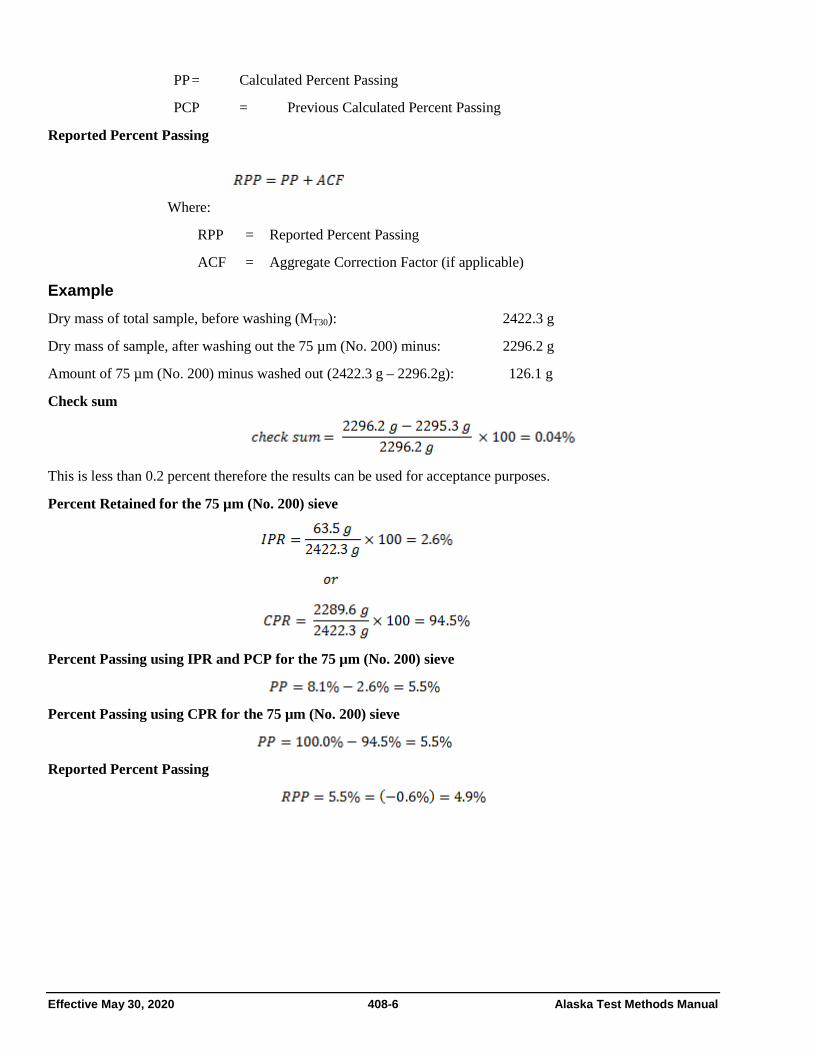
Effective May 30, 2020 408-6 Alaska Test Methods Manual
PP = Calculated Percent Passing
PCP = Previous Calculated Percent Passing
Reported Percent Passing
Where:
RPP = Reported Percent Passing
ACF = Aggregate Correction Factor (if applicable)
Example Dry mass of total sample, before washing (MT30): 2422.3 g
Dry mass of sample, after washing out the 75 µm (No. 200) minus: 2296.2 g
Amount of 75 µm (No. 200) minus washed out (2422.3 g – 2296.2g): 126.1 g
Check sum
This is less than 0.2 percent therefore the results can be used for acceptance purposes.
Percent Retained for the 75 µm (No. 200) sieve
Percent Passing using IPR and PCP for the 75 µm (No. 200) sieve
Percent Passing using CPR for the 75 µm (No. 200) sieve
Reported Percent Passing

Alaska Test Methods Manual 408-7 Effective May 30, 2020
Individual Gradation on All Sieves
Sieve Size mm (in.)
Individual Mass
Retained g
(IMR)
Determine IPR Divide IMR by M
and multiply by 100
Individual Percent
Retained (IPR)
Determine PP by subtracting IPR
from Previous PP
Percent Passing
(PP)
Agg. Corr. Factor from T 308 (ACF)
Reported Percent Passing*
19.0 (3/4) 0 0 100.0 100
12.5 (1/2) 346.9
14.3 85.7 86
9.5 (3/8) 207.8
8.6 77.1 77
4.75 (No. 4) 625.4
25.8 51.3 51
2.36 (No. 8) 416.2
17.2 34.1 34
1.18 (No. 16) 274.2
11.3 22.8 23
0.600 (No. 30) 152.1
6.3 16.5 17
0.300 (No. 50) 107.1
4.4 12.1 12
0.150 (No. 100) 96.4
4.0 8.1 8
0.075 (No. 200) 63.5
2.6 5.5 -0.6
4.9
minus 75 µm
(No. 200) in the pan
5.7
Total mass after sieving = sum of sieves + mass in the pan = 2295.3 g Dry mass of total sample, before washing (MT30): 2422.3g * Report total percent passing to 1 percent except report the 75 µm (No. 200) sieve to 0.1 percent.

Effective May 30, 2020 408-8 Alaska Test Methods Manual
Cumulative Gradation on All Sieves
Sieve Size mm (in.)
Cumulative Mass
Retained g
(CMR)
Determine CPR Divide CMR by M
and multiply by 100
Cumulative Percent
Retained (CPR)
Determine PP by subtracting CPR
from 100.0
Percent Passing
(PP)
Agg. Corr. Factor from T 308 (ACF)
Reported Percent Passing*
19.0 (3/4) 0 0.0 100.0 100
12.5 (1/2) 346.9
14.3 85.7 86
9.5 (3/8) 554.7
22.9 77.1 77
4.75 (No. 4) 1180.1
48.7 51.3 51
2.36 (No. 8) 1596.3
65.9 34.1 34
1.18 (No. 16) 1870.5
77.2 22.8 23
0.600 (No. 30) 2022.6
83.5 16.5 17
0.300 (No. 50) 2129.7
87.9 12.1 12
0.150 (No. 100) 2226.1
91.9 8.1 8
0.075 (No. 200) 2289.6
94.5 5.5 -0.6
4.9
minus 75 µm
(No. 200) in the pan
2295.3
Total mass after sieving = 2295.3 g
Dry mass of total sample, before washing (MT30): 2422.3g * Report total percent passing to 1 percent except report the 75 µm (No. 200) sieve to 0.1 percent.

Alaska Test Methods Manual 408-9 Effective May 30, 2020
Report
• Results on forms approved by the agency
• Sample ID
• Depending on the agency, this may include:
- Individual mass retained on each sieve
- Individual percent retained on each sieve
- Cumulative mass retained on each sieve
- Cumulative percent retained on each sieve
- Aggregate Correction Factor for each sieve from AASHTO T 308
- Calculated percent passing each sieve to 0.1 percent
• Percent passing to the nearest 1 percent, except 75 µm (No. 200) sieve to the nearest 0.1 percent.

Effective May 30, 2020 408-10 Alaska Test Methods Manual
ANNEX A TIME EVALUATION
The minimum time requirement should be evaluated for each shaker at least annually by the following method:
1. Shake the sample over nested sieves for approximately 10 minutes.
2. Provide a snug-fitting pan and cover for each sieve, and hold in a slightly inclined position in one hand.
3. Hand-shake each sieve by striking the side of the sieve sharply and with an upward motion against the heel of the other hand at the rate of about 150 times per minute, turning the sieve about one sixth of a revolution at intervals of about 25 strokes.
If more than 0.5 percent by mass of the total sample before sieving passes any sieve after one minute of continuous hand sieving adjust shaker time and re-check.
In determining sieving time for sieve sizes larger than 4.75 mm (No. 4), limit the material on the sieve to a single layer of particles.

Alaska Test Methods Manual 408-11 Effective May 30, 2020
ANNEX B OVERLOAD DETERMINATION
• For sieves with openings smaller than 4.75 mm (No. 4), the mass retained on any sieve shall not exceed 7 kg/m2 (4 g/in2) of sieving surface.
• For sieves with openings 4.75 mm (No. 4) and larger, the mass (in kg) shall not exceed the product of 2.5 x (sieve opening in mm) x (effective sieving area). See Table B1.
Additional sieves may be necessary to keep from overloading the specified sieves. The sample may also be sieved in increments or sieves with a larger surface area.
TABLE B1
Maximum Allowable Mass of Material Retained on a Sieve, g Nominal Sieve Size, mm (in.)
Exact size is smaller (see AASHTO T 27)
Sieve Size mm (in.)
203 dia (8)
305 dia (12)
305 by 305 (12 × 12)
350 by 350 (14 × 14)
372 by 580 (16 × 24)
Sieving Area m2
0.0285 0.0670 0.0929 0.1225 0.2158
90 (3 1/2) * 15,100 20,900 27,600 48,500
75 (3) * 12,600 17,400 23,000 40,500
63 (2 1/2) * 10,600 14,600 19,300 34,000
50 (2) 3600 8400 11,600 15,300 27,000
37.5 (1 1/2) 2700 6300 8700 11,500 20,200
25.0 (1) 1800 4200 5800 7700 13,500
19.0 (3/4) 1400 3200 4400 5800 10,200
16.0 (5/8) 1100 2700 3700 4900 8600
12.5 (1/2) 890 2100 2900 3800 6700
9.5 (3/8) 670 1600 2200 2900 5100
6.3 (1/4) 440 1100 1500 1900 3400
4.75 (No. 4) 330 800 1100 1500 2600
-4.75 (-No. 4) 200 470 650 860 1510

Effective May 30, 2020 408-12 Alaska Test Methods Manual
This page intentionally left blank.

Alaska Test Methods Manual 409-1 Effective May 30, 2020
ATM 409 THEORETICAL MAXIMUM SPECIFIC GRAVITY (Gmm) AND DENSITY OF ASPHALT MIXTURES
Following are guidelines for the use of WAQTC FOP for AASHTO T 209 by the State of Alaska DOT&PF.
1. Delete Table 1 and replace with the Table 3
Table 3 Test Sample Size for Maximum Specific Gravity
Nominal Maximum Aggregate Size*
mm (in.)
Minimum Mass
g
25 (1) 2500
19 (3/4) 2000
12.5 (1/2) 1500
9.5 (3/8) 1000
4.75 (No. 4) 500
* One sieve larger than the first sieve to retain more than 10 percent of the material using an agency specified set of sieves based on cumulative percent retained. Where large gaps in specification sieves exist, intermediate sieve(s) may be inserted to determine nominal maximum.
2. Density Correction for temperature variation is discontinued.

Effective May 30, 2020 409-2 Alaska Test Methods Manual
This page intentionally left blank.

Alaska Test Methods Manual 409-3 Effective May 30, 2020
THEORETICAL MAXIMUM SPECIFIC GRAVITY (GMM) AND DENSITY OF ASPHALT MIXTURES FOP FOR AASHTO T 209
Scope This procedure covers the determination of the maximum specific gravity (Gmm) of uncompacted asphalt mixtures in accordance with AASHTO T 209-19. Two methods using different containers – bowl and pycnometer / volumetric flask– are covered.
Specimens prepared in the laboratory shall be cured according to agency standards.
Apparatus
• Balance or scale: 10,000 g capacity, readable to 0.1 g
• Container: A glass, metal, or plastic bowl, pycnometer or volumetric flask between 2000 and 10,000 mL as required by the minimum sample size requirements in Table 1 sample and capable of withstanding a partial vacuum
• Pycnometer / volumetric flask cover: A glass plate or a metal or plastic cover with a vented opening
• Vacuum lid: A transparent lid with a suitable vacuum connection, with a vacuum opening to be covered with a fine wire mesh
• Vacuum pump or water aspirator: Capable of evacuating air from the container to a residual pressure of 4.0 kPa (30 mm Hg)
• Residual pressure manometer or vacuum gauge: Traceable to NIST and capable of measuring residual pressure down to 4.0 kPa (30 mm Hg) or less
• Manometer or vacuum gauge: Capable of measuring the vacuum being applied at the source of the vacuum
• Water bath: A constant-temperature water bath (optional)
• Thermometers: Standardized liquid-in-glass, or electronic digital total immersion type, accurate to 0.5°C (1°F)
• Bleeder valve to adjust vacuum
• Automatic vacuum control unit (optional)
• Timer
Standardization of Pycnometer or Volumetric Flask Use a pycnometer / volumetric flask that is standardized to accurately determine the mass of water, at 25 ±0.5°C (77 ±1°F), in the pycnometer / volumetric flask. The pycnometer / volumetric flask shall be standardized periodically in conformance with procedures established by the agency.
Test Sample Preparation 1. Obtain samples in accordance with the FOP for AASHTO R 97 and reduce according to the FOP for
AASHTO R 47.

Effective May 30, 2020 409-4 Alaska Test Methods Manual
2. Test sample size shall conform to the requirements of Table 1. Samples larger than the capacity of the container may be tested in two or more increments. Results will be combined and averaged. If the increments have a specific gravity difference greater than 0.014 the test must be re-run.
Table 1
Test Sample Size for Gmm Nominal Maximum*
Aggregate Size mm (in.)
Minimum Mass
g 37.5 or greater (1½) 4000
19 to 25 (3/4 to 1) 2500 12.5 or smaller (1/2) 1500
*Nominal maximum size: One sieve larger than the first sieve to retain more than 10 percent of the material using an agency specified set of sieves based on cumulative percent retained.
Procedure – General Two procedures – bowl and pycnometer / volumetric flask – are covered. The first 11 steps are the same for both.
1. Separate the particles of the sample, taking care not to fracture the mineral particles, so that the particles of the fine aggregate portion are not larger than 6.3 mm (1/4 in.). If the mixture is not sufficiently soft to be separated manually, place it in a large flat pan and warm in an oven only until it is pliable enough for separation.
2. Cool the sample to room temperature.
3. Determine and record the mass of the dry container to the nearest 0.1 g.
4. Place the sample in the container.
5. Determine and record the mass of the dry container and sample to the nearest 0.1 g.
6. Determine and record the mass of the sample by subtracting the mass determined in Step 3 from the mass determined in Step 5. Designate this mass as “A.”
7. Add sufficient water at approximately 25° C (77° F) to cover the sample by about 25 mm (1 in.).
Note 1: The release of entrapped air may be facilitated by the addition of a wetting agent. Check with the agency to see if this is permitted and, if it is, for a recommended agent.
8. Place the lid on the container and attach the vacuum line. To ensure a proper seal between the container and the lid, wet the O-ring or use a petroleum gel.
9. Remove entrapped air by subjecting the contents to a partial vacuum of 3.7 ±0.3 kPa (27.5 ±2.5 mm Hg) residual pressure for 15 ±2 minutes.
10. Agitate the container and contents, either continuously by mechanical device or manually by vigorous shaking, at 2-minute intervals. This agitation facilitates the removal of air.
11. Release the vacuum. Increase the pressure to atmospheric pressure in 10 to 15 seconds if the vacuum release is not automated. Turn off the vacuum pump and remove the lid. When performing the pycnometer / volumetric flask method, complete steps 12B through 16B within 10±1 minute.

Alaska Test Methods Manual 409-5 Effective May 30, 2020
Procedure – Bowl
12A. Fill the water bath to overflow level with water at 25 ±1°C (77 ±2°F) and allow the water to stabilize.
13A. Zero or tare the balance with the immersion apparatus attached, ensuring that the device is not touching the sides or the bottom of the water bath.
14A. Suspend and immerse the bowl and contents in water at 25 ±1°C (77 ±2°F) for 10 ±1 minutes. The holder shall be immersed sufficiently to cover both it and the bowl.
15A. Determine and record the submerged weight of the bowl and contents to the nearest 0.1 g.
16A. Refill the water bath to overflow level.
17A. Empty and re-submerge the bowl following Step 12A to determine the submerged weight of the bowl to the nearest 0.1 g.
18A. Determine and record the submerged weight of the sample to the nearest 0.1 g by subtracting the submerged weight of the bowl from the submerged weight determined in Step 15A. Designate this submerged weight as “C.”
Procedure – Pycnometer or Volumetric Flask
12B. Immediately fill the pycnometer / volumetric flask with water without reintroducing air.
13B. Stabilize the temperature of the pycnometer / volumetric flask and contents so that the final temperature is within 25 ±1°C (77 ±2°F).
14B. Finish filling the pycnometer / volumetric flask with water that is 25 ±1°C (77 ±2°F), place the cover or a glass plate on the pycnometer / volumetric flask, and eliminate all air. Note 2: When using a metal pycnometer and cover, place the cover on the pycnometer and push down slowly, forcing excess
water out of the hole in the center of the cover. Use care when filling the pycnometer to avoid reintroducing air into the water.
15B. Towel dry the outside of the pycnometer / volumetric flask and cover.
16B. Determine and record the mass of the pycnometer / volumetric flask, cover, de-aired water, and sample to the nearest 0.1 g. within 10 ±1 minutes of completion of Step 11. Designate this mass as “E.”

Effective May 30, 2020 409-6 Alaska Test Methods Manual
Procedure – Mixtures Containing Uncoated Porous Aggregate If the pores of the aggregates are not thoroughly sealed by a bituminous film, they may become saturated with water during the vacuuming procedure, resulting in an error in maximum density. To determine if this has occurred, complete the general procedure and then:
1. Carefully drain water from sample through a towel held over the top of the container to prevent loss of material.
2. Spread sample in a flat shallow pan and place before an electric fan to remove surface moisture.
3. Determine the mass of the sample when the surface moisture appears to be gone.
4. Continue drying and determine the mass of the sample at 15-minute intervals until less than a 0.5 g loss is found between determinations.
5. Record the mass as the saturated surface dry mass to the nearest 0.1 g. Designate this mass as “ASSD.”
6. Calculate, as indicated below, Gmm using “A” and “ASSD,” and compare the two values.
Calculation Calculate the Gmm to three decimal places as follows:
Bowl Procedure
(for mixes containing uncoated aggregate materials) Where:
A = mass of dry sample in air, g ASSD = Mass of saturated surface dry sample in air, g C = submerged weight of sample in water, g
Example:
A = 1432.7 g ASSD = 1434.2 g C = 848.6 g
Pycnometer / Volumetric Flask Procedure
(for mixtures containing uncoated materials) Where:
A = Mass of dry sample in air, g ASSD = Mass of saturated surface-dry sample in air, g D = Mass of pycnometer / volumetric flask filled with water at 25°C (77°F), g, determined during
the Standardization of Pycnometer / Volumetric Flask procedure

Alaska Test Methods Manual 409-7 Effective May 30, 2020
E = Mass of pycnometer / volumetric flask filled with water and the test sample at test temperature, g
Example (in which two increments of a large sample are averaged):
Increment 1 Increment 2 A = 2200.3 g A = 1960.2 g D = 7502.5 g D = 7525.5 g E = 8812.0 g E = 8690.8 g Temperature = 26.2°C Temperature = 25.0°C
Allowable variation is: 0.014
2.470 - 2.466 = 0.004, which is < 0.014, so they can be averaged.
Average: 2.470 + 2.466 = 4.936 4.936 ÷ 2 = 2.468
Theoretical Maximum Density To calculate the theoretical maximum density at 25°C (77°F) use one of the following formulas. The density of water at 25°C (77°F) is 997.1 in Metric units or 62.245 in English units.
Theoretical maximum density kg/m3 = Gmm × 997.1 kg/ m3
2.468 × 997.1 kg/ m3 = 2461 kg/ m3
or
Theoretical maximum density lb/ft3 = Gmm × 62.245 lb/ft3
2.468 × 62.245 lb/ft3 = 153.6 lb/ft3
Report
• Results on forms approved by the agency
• Sample ID
• Gmm to the nearest 0.001
• Theoretical maximum density to the nearest 1 kg/m3 (0.1 lb/ft3)

Effective May 30, 2020 409-8 Alaska Test Methods Manual
This page intentionally left blank.

Alaska Test Methods Manual 410-1 Effective May 30, 2020
ATM 410 Bulk Specific Gravity (Gmb) of Compacted Hot Mix Asphalt (HMA) Using Saturated Surface-Dry Specimens
Following are guidelines for the use of WAQTC FOP for AASHTO T 166 by the State of Alaska DOT&PF.
1. Report compaction to the 0.1%. Calculate as follows:
Where:
Cp = Percent Compaction Gmm = Theoretical Maximum Specific Gravity Gmb = Bulk Specific Gravity
2. Method C/A may be used on DOT&PF projects, regardless of the absorption calculated.
3. AASHTO T 331, Standard Method of Test for Bulk Specific Gravity (Gmb) and Density of Compacted Asphalt Mixtures Using Automatic Vacuum Sealing Method, may be used.
4. As an alternate to drying to constant mass in an oven, ASTM D 7227 may be used.

Effective May 30, 2020 410-2 Alaska Test Methods Manual
This page intentionally left blank.
Alaska Test Methods Manual 410-3 Effective May 30, 2020
BULK SPECIFIC GRAVITY (GMB) OF COMPACTED ASPHALT MIXTURES USING SATURATED SURFACE-DRY SPECIMENS FOP FOR AASHTO T 166
Scope This procedure covers the determination of bulk specific gravity (Gmb) of compacted asphalt mixtures using three methods – A, B, and C – in accordance with AASHTO T 166-16. This FOP is for use on specimens not having open or interconnecting voids or absorbing more than 2.00 percent water by volume, or both. When specimens have open or interconnecting voids or absorbing more than 2.00 percent water by volume, or both, AASHTO T 275 or AASHTO T 331 should be performed.
Overview
• Method A: Suspension • Method B: Volumeter • Method C: Rapid test for A or B
Test Specimens Test specimens may be either laboratory-molded or from asphalt mixture pavement. For specimens it is recommended that the diameter be equal to four times the maximum size of the aggregate and the thickness be at least one and one half times the maximum size.
Test specimens from asphalt mixture pavement will be sampled according to AASHTO R 67.
Terminology Constant Mass: The state at which a mass does not change more than a given percent, after additional drying for a defined time interval, at a required temperature.
Apparatus - Method A (Suspension)
• Balance or scale: 5 kg capacity, readable to 0.1 g, and fitted with a suitable suspension apparatus and holder to permit weighing the specimen while suspended in water, conforming to AASHTO M 231.
• Suspension apparatus: Wire of the smallest practical size and constructed to permit the container to be fully immersed.
• Water bath: For immersing the specimen in water while suspended under the balance or scale and equipped with an overflow outlet for maintaining a constant water level.
• Towel: Damp cloth towel used for surface drying specimens.
• Oven: Capable of maintaining a temperature of 110 ±5°C (230 ±9°F) for drying the specimens to a constant mass.
• Pan: Pan or other suitable container of known mass, large enough to hold a sample for drying in oven.
• Thermometer: Having a range of 19 to 27°C (66 to 80°F), graduated in 0.1°C (0.2°F) subdivisions.
• Vacuum device: refer to AASHTO R 79 (optional)
Procedure - Method A (Suspension) Recently molded laboratory samples that have not been exposed to moisture do not need drying.
1. Dry the specimen to constant mass, if required.

Effective May 30, 2020 410-4 Alaska Test Methods Manual
a. Oven method
i. Initially dry overnight at 52 ±3°C (125 ±5°F).
ii. Determine and record the mass of the specimen (Mp).
iii. Return the specimen to the oven for at least 2 hours.
iv. Determine and record the mass of the specimen (Mn).
v. Determine percent change by subtracting the new mass determination (Mn) from the previous mass determination (Mp), divide by the previous mass determination (Mp), and multiply by 100.
vi. Continue drying until there is no more than 0.05 percent change in specimen mass after 2-hour drying intervals (constant mass).
vii. Constant mass has been achieved, sample is defined as dry.
Note 1: To expedite the procedure, steps 1 and 2 may be performed last. To further expedite the process, see Method C.
b. Vacuum dry method
i. Perform vacuum drying procedure according to AASHTO R 79.
ii. Determine and record the mass of the specimen (Mp).
iii. Perform a second vacuum drying procedure.
iv. Determine and record the mass of the specimen (Mn).
v. Determine percent change by subtracting the new mass determination (Mn) from the previous mass determination (Mp), divide by the previous mass determination (Mp), and multiply by 100.
vi. Continue drying until there is no more than 0.05 percent change in specimen mass (constant mass).
vii. Constant mass has been achieved, sample is defined as dry.
2. Cool the specimen in air to 25 ±5°C (77 ±9°F), and determine and record the dry mass to the nearest 0.1 g. Designate this mass as “A.”
3. Fill the water bath to overflow level with water at 25 ±1°C (77 ±1.8°F) and allow the water to stabilize.
4. Zero or tare the balance with the immersion apparatus attached, ensuring that the device is not touching the sides or the bottom of the water bath.
5. Immerse the specimen shaking to remove the air bubbles. Place the specimen on its side in the suspension apparatus. Leave it immersed for 4 ±1 minutes.
6. Determine and record the submerged weight to the nearest 0.1 g. Designate this submerged weight as “C.”
7. Remove the sample from the water and quickly surface dry with a damp cloth towel within 5 seconds.
8. Zero or tare the balance.
9. Immediately determine and record the mass of the saturated surface-dry (SSD) specimen to nearest 0.1 g. Designate this mass as “B.” Any water that seeps from the specimen during the mass determination is considered part of the saturated specimen. Do not to exceed 15 seconds performing Steps 7 through 9.

Alaska Test Methods Manual 410-5 Effective May 30, 2020
Calculations - Method A (Suspension)
Constant Mass: Calculate constant mass using the following formula:
Where:
Mp = previous mass measurement, g Mn = new mass measurement, g Bulk specific gravity (Gmb) and percent water absorbed:
Where:
A = Mass of dry specimen in air, g B = Mass of SSD specimen in air, g C = Weight of specimen in water at 25 ±1°C (77 ±1.8°F), g
Example:
Apparatus - Method B (Volumeter)
• Balance or scale: 5 kg capacity, readable to 0.1 g and conforming to AASHTO M 231.
• Water bath: Thermostatically controlled to 25 ±0.5°C (77 ±0.9°F).
• Thermometer: Range of 19 to 27°C (66 to 80°F), and graduated in 0.1°C (0.2°F) subdivisions.
• Volumeter: Calibrated to 1200 mL or appropriate capacity for test sample and having a tapered lid with a capillary bore.
• Oven: Capable of maintaining a temperature of 110 ±5°C (230 ±9°F) for drying the specimens to a constant mass.
• Pan: Pan or other suitable container of known mass, large enough to hold a sample for drying in oven.
• Towel: Damp cloth towel used for surface drying specimens.
• Vacuum device: AASHTO R 79 (optional)
Procedure - Method B (Volumeter) Recently molded laboratory samples that have not been exposed to moisture do not need drying.

Effective May 30, 2020 410-6 Alaska Test Methods Manual
1. Dry the specimen to constant mass, if required.
a. Oven method:
i. Initially dry overnight at 52 ±3°C (125 ±5°F).
ii. Determine and record the mass of the specimen (Mp).
iii. Return the specimen to the oven for at least 2 hours.
iv. Determine and record the mass of the specimen (Mn).
v. Determine percent change by subtracting the new mass determination (Mn) from the previous mass determination (Mp), divide by the previous mass determination (Mp), and multiply by 100.
vi. Continue drying until there is no more than 0.05 percent change in specimen mass after 2-hour drying intervals (constant mass).
vii. Constant mass has been achieved, sample is defined as dry.
Note 1: To expedite the procedure, steps 1 and 2 may be performed last. To further expedite the process, see Method C.
b. Vacuum dry method
i. Perform vacuum drying procedure according to AASHTO R 79.
ii. Determine and record the mass of the specimen (Mp).
iii. Perform a second vacuum drying procedure.
iv. Determine and record the mass of the specimen (Mn).
v. Determine percent change by subtracting the new mass determination (Mn) from the previous mass determination (Mp). Divide by the previous mass determination (Mp). And multiply by 100.
vi. Continue drying until there is no more than 0.05 percent change in specimen mass (constant mass).
vii. Constant mass has been achieved, sample is defined as dry.
2. Cool the specimen in air to 25 ±5°C (77 ±9°F), and determine and record the dry mass to the nearest 0.1 g. Designate this mass as “A.”
3. Immerse the specimen in the temperature-controlled water bath for at least 10 minutes.
4. Fill the volumeter with distilled water at 25 ±1°C (77 ±1.8°F) making sure some water escapes through the capillary bore of the tapered lid.
5. Wipe the volumeter dry. Determine the mass of the volumeter to the nearest 0.1 g. Designate this mass as “D.”
6. At the end of the ten minute period, remove the specimen from the water bath and quickly surface dry with a damp cloth towel within 5 seconds.
7. Immediately determine and record the mass of the SSD specimen to the nearest 0.1 g. Designate this mass as “B.” Any water that seeps from the specimen during the mass determination is considered part of the saturated specimen.
8. Place the specimen in the volumeter and let stand 60 seconds.

Alaska Test Methods Manual 410-7 Effective May 30, 2020
9. Bring the temperature of the water to 25 ±1°C (77 ±1.8°F) and cover the volumeter, making sure some water escapes through the capillary bore of the tapered lid.
10. Wipe the volumeter dry.
11. Determine and record the mass of the volumeter and specimen to the nearest 0.1 g. Designate this mass as “E.”
Note 2: Method B is not acceptable for use with specimens that have more than 6 percent air voids.
Calculations - Method B (Volumeter) Constant Mass:
Calculate constant mass using the following formula:
Where:
Mp = previous mass measurement, g
Mn = new mass measurement, g
Bulk specific gravity (Gmb) and percent water absorbed:
Where:
Gmb = Bulk specific gravity A = Mass of dry specimen in air, g B = Mass of SSD specimen in air, g D = Mass of volumeter filled with water at 25 ±1°C (77 ±1.8°F), g E = Mass of volumeter filled with specimen and water, g
Example:
Method C (Rapid Test for Method A or B) See Methods A or B.
Note 3: This procedure can be used for specimens that are not required to be saved and contain substantial amounts of moisture. Cores can be tested the same day as obtained by this method.
Procedure - Method C (Rapid Test for Method A or B) 1. Start on Step 3 of Method A or B, and complete that procedure, then determine dry mass, “A,” as follows.

Effective May 30, 2020 410-8 Alaska Test Methods Manual
2. Determine and record mass of a large, flat-bottom container.
3. Place the specimen in the container.
4. Place in an oven at a minimum of 105°C (221°F). Do not exceed the Job Mix Formula mixing temperature.
5. Dry until the specimen can be easily separated into fine aggregate particles that are not larger than 6.3 mm (¼ in.).
6. Determine and record the mass of the specimen (Mp).
7. Return the specimen to the oven for at least 2 hours.
8. Determine and record the mass of the specimen (Mn).
9. Determine percent change by subtracting the new mass determination (Mn) from the previous mass determination (Mp), divide by the previous mass determination (Mp), and multiply by 100.
10. Continue drying until there is no more than 0.05 percent change in specimen mass after 2-hour drying intervals (constant mass).
11. Constant mass has been achieved; sample is defined as dry.
12. Cool in air to 25 ±5°C (77 ±9°F).
13. Determine and record the mass of the container and dry specimen to the nearest 0.1 g.
14. Determine and record the mass of the dry specimen to the nearest 0.1 g by subtracting the mass of the container from the mass determined in Step 13. Designate this mass as “A.”
Calculations - Method C (Rapid Test for Method A or B) Complete the calculations as outlined in Methods A or B, as appropriate.
Report
• Results on forms approved by the agency
• Sample ID
• Gmb to the nearest 0.001
• Absorption to the nearest 0.01 percent
• Method performed.

Alaska Test Methods Manual 411-1 Effective May 30, 2020
ATM 411 In-Place Density of Asphalt Mixtures By Nuclear Method FOP For AASHTO T 355
Following are guidelines for the use of WAQTC FOP for AASHTO T 355 by the State of Alaska DOT&PF. Replaces WAQTC TM 8.
1. Testing under this method shall be used for quality control and when specified, acceptance testing.
2. Report percent compaction to the nearest 0.1 percent. Report percent air voids, if required.
3. Any offsets determined are GAUGE-SPECIFIC and must be determined for each gauge used to test the material.
4. When The Standard Density is determined using ATM 412, use the average of the tests performed according to ATM 411, taken at three separate random test locations, as the acceptance test value.
5. Direct transmission may be used on crushed asphalt materials.
For direct Transmission use the following procedure:
Procedure
Direct Transmission
1. Maximum contact between the base of the gauge and the surface of the material under test is critical.
2. Use the guide and scraper plate as a template and drill a hole to a depth of at least 7 mm (1/4 in.) deeper than the measurement depth required for the gauge.
3. Place the gauge on the prepared surface so the source rod can enter the hole. Insert the probe in the hole and lower the source rod to the desired test depth using the handle and trigger mechanism. Position the gauge with the long axis of the gauge parallel to the direction of paving. Pull the gauge so that the probe is firmly against the side of the hole.
4. Take one four-minute test and record the wet density (WD) reading.

Effective May 30, 2020 411-2 Alaska Test Methods Manual
This page intentionally left blank.
Alaska Test Methods Manual 411-3 Effective May 30, 2020
IN-PLACE DENSITY OF ASPHALT MIXTURES BY NUCLEAR METHOD FOP FOR AASHTO T 355
Scope
This test method describes a procedure for determining the density of asphalt mixtures by means of a nuclear gauge using the backscatter method in accordance with AASHTO T 355-18. Correlation with densities determined under the FOP for AASHTO T 166 is required by some agencies.
Apparatus
• Nuclear density gauge with the factory-matched standard reference block.
• Transport case for properly shipping and housing the gauge and tools.
• Instruction manual for the specific make and model of gauge.
• Radioactive materials information and calibration packet containing:
− Daily standard count log
− Factory and laboratory calibration data sheet
− Leak test certificate
− Shippers’ declaration for dangerous goods
− Procedure memo for storing, transporting and handling nuclear testing equipment
− Other radioactive materials documentation as required by local regulatory requirements
Material
• Filler material: Fine-graded sand from the source used to produce the asphalt pavement or other agency approved materials.
Radiation Safety
This method does not purport to address all of the safety problems associated with its use. This test method involves potentially hazardous materials. The gauge utilizes radioactive materials that may be hazardous to the health of the user unless proper precautions are taken. Users of this gauge must become familiar with the applicable safety procedures and governmental regulations. All operators will be trained in radiation safety prior to operating nuclear density gauges. Some agencies require the use of personal monitoring devices such as a thermoluminescent dosimeter or film badge. Effective instructions, together with routine safety procedures such as source leak tests, recording and evaluation of personal monitoring device data, etc., are a recommended part of the operation and storage of this gauge.

Effective May 30, 2020 411-4 Alaska Test Methods Manual
Calibration
Calibrate the nuclear gauge as required by the agency. This calibration may be performed by the agency using the manufacturer’s recommended procedures or by other facilities approved by the agency. Verify or re-establish calibration curves, tables, or equivalent coefficients every 12 months.
Standardization
1. Turn the gauge on and allow it to stabilize (approximately 10 to 20 minutes) prior to standardization. Leave the power on during the day’s testing.
2. Standardize the nuclear gauge at the construction site at the start of each day’s work and as often as deemed necessary by the operator or agency. Daily variations in standard count shall not exceed the daily variations established by the manufacturer of the gauge. If the daily variations are exceeded after repeating the standardization procedure, the gauge should be repaired, recalibrated, or both.
3. Record the standard count for both density and moisture in the daily standard count log. The exact procedure for standard count is listed in the manufacturer’s Operator’s Manual.
Note 1: New standard counts may be necessary more than once a day. See agency requirements.
Test Site Location
1. Select a test location(s) randomly and in accordance with agency requirements. Test sites should be relatively smooth and flat and meet the following conditions:
a. At least 10 m (30 ft.) away from other sources of radioactivity.
b. At least 3 m (10 ft.) away from large objects.
c. If the gauge will be closer than 600 mm (24 in.) to any vertical mass, or less than 300 mm (12 in.) from a vertical pavement edge, use the gauge manufacturer’s correction procedure.
Procedure
1. Maintain maximum contact between the base of the gauge and the surface of the material under test.
2. Use filler material to fill surface voids.
3. Spread a small amount of filler material over the test site surface and distribute it evenly. Strike off the surface with a straightedge (such as a lathe or flat-bar steel) to remove excess material.
4. If using thin-layer mode, enter the anticipated overlay thickness into the gauge.
Note 2: If core correlation is required, entered thickness, anticipated thickness, and nominal core thickness may be required to match.
Method A – Average of two one-minute tests
1. Place the gauge on the test site, perpendicular to the roller passes.

Alaska Test Methods Manual 411-5 Effective May 30, 2020
2. Using a crayon (not spray paint), mark the outline or footprint of the gauge.
3. Extend the probe to the backscatter position.
4. Take a one-minute test and record the wet density reading.
5. Rotate the gauge 90 degrees centered over the original footprint. Mark the outline or footprint of the gauge.
6. Take another one-minute test and record the wet density reading.
7. If the difference between the two one-minute tests is greater than 40 kg/m3 (2.5 lb/ft3), retest in both directions. If the difference of the retests is still greater than 40 kg/m3 (2.5 lb/ft3) test at 180 and 270 degrees.
8. The density reported for each test site shall be the average of the two individual one-minute wet density readings.
Method B – One four-minute test
1. Place the gauge on the test site, parallel to the roller passes.
2. Using a crayon (not spray paint), mark the outline or footprint of the gauge.
3. Extend the probe to the backscatter position.
4. Take one 4-minute test and record the wet density reading.
Method A Footprint of the gauge test site
Direction of roller pass

Effective May 30, 2020 411-6 Alaska Test Methods Manual
Calculation of Results
Percent compaction is determined by comparing the in-place wet density as determined by this method to the appropriate agency density standard. See appropriate agency policy for use of density standards.
Method A Example:
Reading #1: 141.5 lb/ft3
Reading #2: 140.1 lb/ft3 Are the two readings within the tolerance? (YES)
Reading average: 140.8 lb/ft3
Core correction: +2.1 lb/ft3
Corrected reading: 142.9 lb/ft3
Method B Example:
Reading: 140.8 lb/ft3
Core correction: +2.1 lb/ft3
Corrected reading 142.9 lb/ft3
Example percent compaction:
From the FOP for AASHTO T 209:
Gmm = 2.466
Method B Footprint of the gauge test site
Direction of roller pass

Alaska Test Methods Manual 411-7 Effective May 30, 2020
Report
• Results on forms approved by the agency
• Test ID
• Location of test and thickness of layer tested
• Mixture type
• Make, model and serial number of the nuclear moisture-density gauge
• Calculated wet density of each measurement and any adjustment data
• Density standard
• Compaction to the nearest 0.1 percent
• Name and signature of operator

Effective May 30, 2020 411-8 Alaska Test Methods Manual
APPENDIX – CORRELATION WITH CORES
(Nonmandatory Information)
The bulk specific gravity (Gmb) of the core is a physical measurement of the in-place HMA and can be compared with the nuclear density gauge readings. Comparing the core value to the corresponding gauge values, a correlation can be established.
The correlation can then be used to adjust the gauge readings to the in-place density of the cores. The core correlation is gauge specific and must be determined without traffic allowed on the pavement between nuclear density gauge readings and obtaining the core. When using multiple nuclear density gauges each gauge should be correlated to the core locations prior to removal of the core.
When density correlation with the FOP for AASHTO T 166 is required, correlation of the nuclear gauge with pavement cores shall be made on the first day’s paving (within 24 hours) or from a test strip constructed prior to the start of paving. Cores must be taken before traffic is allowed on the pavement.
Correlation with Cores
1. Determine the number of cores required for correlation from the agency’s specifications. Cores shall be located on the first day’s paving or on the test strip. Locate the test sites in accordance with the agency’s specifications. Follow the “Procedure” section above to establish test sites and obtain densities using the nuclear gauge.
2. Obtain a pavement core from each of the test sites according to AASHTO R 67. The core should be taken from the center of the nuclear gauge footprint.
Method A Footprint of the gauge test site. Core location in the center of the footprint.

Alaska Test Methods Manual 411-9 Effective May 30, 2020
Method B Footprint of the gauge test site.
3. Determine the density of the cores by the FOP for AASHTO T 166, Bulk Specific Gravity of Compacted Asphalt Mixtures Using Saturated Surface Dry Specimens.
4. Calculate a correlation factor for the nuclear gauge reading as follows:
a. Calculate the difference between the core density and the average nuclear gauge density at each test site to the nearest 1 kg/m3 (0.1 lb/ft3). Calculate the average difference and standard deviation of the differences for the entire data set to the nearest 1 kg/m3 (0.1 lb/ft3).
b. If the standard deviation of the differences is equal to or less than 40 kg/m3 (2.5 lb/ft3), the correlation factor applied to the average nuclear gauge density shall be the average difference calculated above in 4.a.
c. If the standard deviation of the differences is greater than 40 kg/m3 (2.5 lb/ft3), the test site with the greatest variation from the average difference shall be eliminated from the data set and the data set properties and correlation factor recalculated following 4.a and 4.b.
d. If the standard deviation of the modified data set still exceeds the maximum specified in 4.b, additional test sites will be eliminated from the data set and the data set properties and correlation factor recalculated following 4.a and 4.b. If the data set consists of less than five test sites, additional test sites shall be established.
Note A1: The exact method used in calculating the nuclear gauge correlation factor shall be defined by agency policy.
Note A2: The above correlation procedure must be repeated if there is a new job mix formula. Adjustments to the job mix formula beyond tolerances established in the contract documents will constitute a new job mix formula. A correlation factor

Effective May 30, 2020 411-10 Alaska Test Methods Manual
established using this procedure is only valid for the particular gauge used in the correlation procedure. If another gauge is brought onto the project, it shall be correlated using the same procedure. Multiple gauges may be correlated from the same series of cores if done at the same time.
Note A3: For the purpose of this procedure, a job mix formula is defined as the percent and grade of paving asphalt used with a specified gradation of aggregate from a designated aggregate source. A new job mix formula may be required whenever compaction of the wearing surface exceeds the agency’s specified maximum density or minimum air voids.
Calculations
Correlation Factor
Where: ∑ = Sum x = Difference from the average Difference n-1 = number of data sets minus 1
Example
Core #
Core results from T 166:
Average Gauge reading Difference: x x2
1 144.9 lb/ft3 142.1 lb/ft3 2.8 lb/ft3 -0.7 0.49 2 142.8 lb/ft3 140.9 lb/ft3 1.9 lb/ft3 0.2 0.04 3 143.1 lb/ft3 140.7 lb/ft3 2.4 lb/ft3 -0.3 0.09 4 140.7 lb/ft3 138.9 lb/ft3 1.8 lb/ft3 0.3 0.09 5 145.1 lb/ft3 143.6 lb/ft3 1.5 lb/ft3 0.6 0.36 6 144.2 lb/ft3 142.4 lb/ft3 1.8 lb/ft3 0.3 0.09 7 143.8 lb/ft3 141.3 lb/ft3 2.5 lb/ft3 -0.4 0.16 8 142.8 lb/ft3 139.8lb/ft3 3.0 lb/ft3 0.9 0.81 9 144.8 lb/ft3 143.3 lb/ft3 1.5 lb/ft3 -0.6 0.36 10 143.0 lb/ft3 141.0 lb/ft3 2.0 lb/ft3 -0.1 0.01 Average Difference:
+2.1 lb/ft3 Ʃx2 = 2.5
Number of data sets
Standard deviation

Alaska Test Methods Manual 411-11 Effective May 30, 2020
Where: Sum of x2 = 2.5 Number of data sets = 9 The standard deviation of 0.53 is less than 2.5 therefore no cores are eliminated. The average difference from all ten cores is used.

Effective May 30, 2020 411-12 Alaska Test Methods Manual
This page intentionally left blank.

Alaska Test Methods Manual 412-1 Effective May 30, 2020
ATM 412 Relative Standard Density of Treated Mixtures by the Control Strip Method
1. Scope This method describes a procedure for determining the relative standard wet density of a material by the control strip testing method. This is applicable to granular materials that are bound together with asphalt binders and/or portland cement.
Standard density values established with this method are GAUGE-SPECIFIC and must be determined for each gauge used in acceptance testing of the material. Assurance checks should be of uncorrected wet density readings.
2. Significance and Use In testing some HMAs, determining the standard density may be difficult with conventional test methods used in the laboratory. When these problems occur a method that allows the determination of a relative standard density in the field can facilitate the verification of compaction efforts. This method describes a procedure to determine the relative standard density to be used in these circumstances.
3. Apparatus
• Nuclear Moisture/Density Gauge—Calibrate and standardize in accordance with ATM 411.
• Compaction equipment that meets the requirements of the contract and of sufficient size and compaction energy to compact the material.
4. Site Preparation 1. The engineer will designate the location and the size of the control strip, as well as minimum compaction
equipment to be used.
2. The subgrade will be compacted to a minimum density equal to that required for the material being tested. When the compaction is complete, the Engineer will approve the surface.
3. A representative lift of the material being evaluated will be placed and prepared for compaction.
5. Procedure 1. Attention should be paid to the requirements of the product being placed so that any binder content,
temperature and/or moisture requirements are maintained in an acceptable range.
2. A minimum of 3 test locations will be selected with-in the control strip. The locations will be in the middle 1/2 of the control strip and at least 12 in from the edge of the control strip. The Engineer will select test locations.
3. The locations will be marked in such a way as not to be lost during the compaction of the control strip. This can be accomplished by marking the side of the strip with stakes or surveyors tape, or by marking with paint beside the location on the control strip.
4. Care should be taken when choosing and preparing the test location so that it is flat and the surface voids filled. If necessary, use a small quantity of dry sand to fill the voids. This layer will in no case be more than 1/8 in in depth.
5. Tests shall be taken in backscatter mode. (Direct transmission may be used on crushed asphalt products.) A test will consist of one 1 minute reading or the average of two 15 second readings (fast mode). Record

Effective May 30, 2020 412-2 Alaska Test Methods Manual
all readings of wet density and moisture content. In the case of the 15 second readings calculate the average wet density determination at each location.
6. After the first pass with the compaction equipment, an initial density test is taken and recorded.
Note 1: One pass of the roller will be defined as one roll over the location.
7. After each subsequent pass and for each piece of compaction equipment used, a test is taken at each location and recorded.
8. Continue the compaction and testing cycle until there is a pass with less than 16 kg/m3 (1 lb/ft3) increase in the average wet density of the test locations; and a second consecutive pass with less than 16 kg/m3 (1 lb/ft3) increase in the average wet density of the test locations.
Note 2: If additional passes are performed there is risk that the treated mix will check or crack.
9. Select ten random locations on the completed control strip and test by averaging two one minute counts at each location in accordance with ATM 411. Average the results from the ten locations and this value will be the relative wet standard density for this material.
Note 3: It may be necessary to repeat the procedure for additional roller types depending on the material to be tested and the requirements of sequencing for the finished surface.
10. Additional control strips may be required if there are changes in the material, lift thickness or compaction equipment.
6. Calculations The Relative Standard Density value will be calculated as follows:
( )10
10987654321 AAAAAAAAAADS+++++++++
=
Where: Dw = Relative Standard Wet Density for the material. An = Average Wet Density for random test location n.
7. Report
• Report the average wet density for each pass
• Report the relative standard wet density to the nearest 0.1 lb/ft3

Alaska Test Methods Manual 412-3 Effective May 30, 2020
Figure 412-1 Control Strip Field Worksheet

Effective May 30, 2020 412-4 Alaska Test Methods Manual
Figure 412-2 Control Strip Field Worksheet Example

Alaska Test Methods Manual 413-1 Effective May 30, 2020
ATM 413 Standard Practice for Sampling Asphalt Mixtures after Compaction (Obtaining Cores)
Following are guidelines for the use of AASHTO R 67 by the State of Alaska DOT&PF. (Replaces WAQTC TM 11).
1. When cores are used to determine gauge correlation use:
o ASHTO T 355 for nuclear gauges
o AASHTO T 343 for electronic gauges
When cores are used to determine pavement density, the Bulk Specific Gravity (Gmb) is determined according to WAQTC FOP for AASHTO T 166.
2. While saw cutting is the preferred method, the different layers in a core may be separated by freezing and use of a chisel and hammer or by use of a hammer and chisel alone if a saw is not available. Care must be taken to protect the core from deformation or damage during the separation. If the core is deformed or damaged, it must be discarded and a new core taken.
3. Core locations – Joint cores shall be centered on the longitudinal joint. Mat cores shall be located at least 12” from all joints and outside pavement edge.
4. Core Locations – core locations shall be independent of other sampling.
5. When determining mat depth (thickness), determine and record the length (height) of the core to 5 mm (¼”) in three places and record the average.
6. Damaged cores shall be replaced by cores located within 12” of the original test.
7. When material is sampled by other than DOT&PF personnel or their agent(s), the sampling must be witnessed and possession taken immediately by DOT&PF personnel or their agent(s).
8. Test Site Location
• The number of cores obtained shall be determined by the test procedure or agency requirements.
• Core location(s) shall be determined by the Department.
9. Replace 2. Filling Core Holes in its entirety with:
2. Filling Core Holes Within 24 hours of coring, the contractor shall clean and dry the core-holes, tack the cut wall surfaces with hot asphalt oil, fill the hole with hot mix asphalt (at, or exceeding, compaction temperature) in lifts of loose thickness that will produce a compacted lift thicknesses of approximately 2” and compact each lift with a 4” face diameter Marshal hammer, using a minimum of 50 blows on each lift of compacted asphalt mix placed in the patch. Finished surface of patched hole must be level with existing paving.
10. APPENDIX - Thickness Determination Is required.

Effective May 30, 2020 413-2 Alaska Test Methods Manual
This page intentionally left blank.

Alaska Test Methods Manual 413-3 Effective May 30, 2020
SAMPLING ASPHALT MIXTURES AFTER COMPACTION (OBTAINING CORES) AASHTO R 67-16
Scope
• This method describes the process for removal of a core sample of hot mix asphalt (HMA) from a pavement for laboratory testing. Cores may range in diameter from 2 in. to 12 in.
Safety— This standard does not purport to address all of the safety concerns, if any, associated with its use. It is the responsibility of the user of this standard to establish appropriate safety and health practices and determine the applicability of regulatory limitations prior to use
Significance Samples obtained in accordance with the procedure may be used for measuring pavement thickness and density. Additional testing may be performed as required by the agency.
Apparatus
• Coring Machine – A motor driven core machine shall be used to obtain the sample. The device shall be capable of obtaining a core to the full depth of the HMA and mounted on a platform such that the core barrel is perpendicular to the pavement during the cutting process. A Core Drill Machine of sufficient horsepower and depth to minimize distortion of the compacted cores of HMA.
• Core Bit – The cutting edge of the core drill bit shall be of hardened steel or other suitable material with diamond chips embedded in the metal cutting edge. The core barrel inside diameter shall be as specified.
• Separation Equipment –A saw or other method(s) that provides a clean smooth plane representing the layer to be tested without damaging the specimen.
• Retrieval Device – A device for removing core samples that will preserve the integrity of the core. The device may be a steel rod of suitable length and with a diameter that will fit into the space between the core and the pavement material. There may be a 90 degree bend at the top to form a handle and a 90 degree bend at the bottom, approximately 2 in. (50 mm) long, forming a hook to assist in the retrieval of the core or other suitable device.
Note 1: Suitable devices have been made from steel rods, wire, or banding material.
• Cooling agent such as: water, ice, dry ice, or liquid nitrogen.
• Sample Marking Tool—A lumber crayon, paint stick, pen, or other suitable marking tool to mark the core sample for labeling, identifying the separation layers, identifying the layer to test, or as otherwise necessary
• Package Containers—Suitable packaging containers for securing and transporting the core samples
Procedure 1. For freshly compacted HMA, the core shall be taken when the material has had sufficient amount of time to
cool to prevent damage to the core.
2. To accelerate the coring process, a cooling agent may be used.
3. Provide a means such as water or air to aid in the removal of cuttings and to minimize the generation of heat caused by friction
4. Position the coring machine above the selected location. Engage power and water or air source to coring machine. Slowly advance bit until contact with the HMA surface.

Effective May 30, 2020 413-4 Alaska Test Methods Manual
5. Keep the core bit perpendicular to the HMA surface applying constant pressure during the process.
Note 2: If any portion of the coring machine shifts during the operation, the core may break or distort. Failure to apply constant pressure, or too much pressure, may cause the bit to bind or distort the core.
6. Apply constant downward pressure on the core bit. Failure to apply constant pressure, or too much pressure, may cause the bit to bind or distort the core.
7. Continue the core drilling to the bottom or slightly below the bottom of the asphalt mixture intended to be samples to allow separation of the core sample at the desired depth from the underlying pavement layers.
8. After drilling, separate the core sample from the underlying pavement layers using the retrieval device or other suitable means, without damaging or distorting the sample. Obtain the core sample using the retrieval device.
Note 2: If the core is damaged to a point that it cannot be used for its intended purpose, a new core shall be obtained within 6 in. of the original location
9. Clearly label the core with a sample marking tool.
Filling Core Holes Fill the hole made from the coring operation with HMA, non-shrink grout, or other suitable material. Consolidate or compact the material in the hole, multiple lifts may be required. Ensure that the final surface is level with the surrounding surface.
Packaging And Transporting Samples
• Transport cores in a manner that prevents damage from jarring, rolling or impact with any object.
• Prevent cores from freezing or from excessive heat, 54° C (130° F), during transport.
Note 3: In extreme ambient temperature conditions, an insulated container should be used during transport.
• If the core is damaged in transport to a point it cannot be utilized for its intended purpose the core will not be used
Layer Separation Separate two or more pavement courses, lifts, or layers; on the designated lift line using appropriate separation equipment.
Note 4: Lift lines are often more visible by rolling the core on a flat surface.
Report
• On forms approved by the Department
• Date the cores were obtained
• Paving date
• Coring location
• The lift / layer being evaluated
• Material type
• Average thickness

Alaska Test Methods Manual 413-5 Effective May 30, 2020
• Core identification information, such as nominal-maximum aggregate size of the mixture, asphalt mixture design identification, performance grade of asphalt binder, etc.

Effective May 30, 2020 413-6 Alaska Test Methods Manual
APPENDIX
(Non mandatory Information)
Thickness Determination Measure the thickness of the designated lift according to ASTM D3549/D3549M to the nearest 0.01 ft, 1/8 in., or 3 mm. Calculate an average of three or more measurements taken around the lift.

Alaska Test Methods Manual 414-1 Effective May 30, 2020
ATM 414 Anti-Strip Requirements of Hot Mix Asphalt
1. Scope This method describes a procedure for determining the retention of a bituminous film by aggregate in the presence of water. It is applicable to asphalt cements, cutback asphalts and emulsified asphalts.
2. Apparatus
• Balance or scale: Capacity sufficient for the principle sample mass, readable to 0.1 percent of the total sample mass and meeting the requirements of AASHTO M 231.
• Thermostatically controlled oven capable of maintaining any required constant temperature between 49-150 ±1ºC (120-300 ±2°F).
• A 9.5 mm (⅜") and a 4.75 mm (No. 4) mm sieve conforming to ASTM E11.
• 600 mL beakers, low form glass or plastic type.
• Thermostatically controlled water bath capable of maintaining a temperature of 49 ±1ºC (120 ±2°F).
• Miscellaneous equipment including a steel spatula with stiff blade (approximately ½" wide x 4" long (12.5 mm x 100 mm), glass or plastic containers for mixing samples, and air-tight containers of suitable size for storing bitumen and anti-strip mixtures.
3. Sample Preparation 1. Aggregate:
a. The test aggregate shall be processed in the same manner as that which would be used during the construction process.
b. Dry the aggregate to a constant weight in accordance with WAQTC FOP for AASHTO T 255.
c. Separate the aggregate by sieving to obtain the minus 9.5 mm (⅜") plus (No. 4) material. Reduce this material, in accordance with WAQTC FOP for AASHTO T 248, Method A, to obtain approximately 1200 g.
2. Anti-stripping additive used in testing will be the same brand and type proposed for use on the project.
3. Bitumen and/or emulsified asphalts will be the same type and grade proposed for use in mix design.
4. Procedure 1. For asphalt cement and/or cutback asphalt samples:
a. Thoroughly mix the bitumen samples with the anti-strip additive in the proportions provided in the table below, or as required. If necessary to store this mixture, use airtight containers.
Note 1: After the additive is added to the bitumen standards they shall not be reheated in excess of preheat temperatures as outlined in (1) and (2) below.
Liquid Anti-strip Type Minimum Dose by weight of asphalt binder
Amines based (including plant-derived) 0.25, 0.50, and 0.75 percent Phosphate Ester based 0.25, 0.50, and 0.75 percent Organo-Silane based 0.05, 0.075, and 0.1 percent

Effective May 30, 2020 414-2 Alaska Test Methods Manual
b. Make up 1 or more aggregate specimens per additive content by placing 100 ± 1 g of the aggregate to be tested into individual mixing containers.
c. Preheat aggregate specimens to the temperature of the respective bitumen below:
(1) Asphalt cements: Preheat in oven at a temperature within the binders mixing temperature range for no longer than 30 minutes.
(2) Cut-back asphalts:
Grades 30 to 250. No preheat required.
Grades 800 to 3000: Preheat at 60-90º C (140-195° F) for no longer than 30 minutes.
d. Preheat the bitumen at the respective temperatures above until it can be poured.
e. Add 5.5 ±0.5 g of bitumen-additive mixture to the aggregate specimen(s).
f. Mix the bitumen and aggregate thoroughly until uniformly coated.
g. The bitumen-aggregate specimen(s) shall be oven-cured at a temperature 60 ± 1º C (140 ±2° F) for a minimum of 18 hours but no more than 24 hours.
h. Remove the sample(s) from the oven and re-mix to obtain a uniform coating. Allow the specimen(s) to cool to a temperature of 49ºC (120°F) or less.
i. Place 50 ±1 g of each of the coated aggregates into individual 600 ml. beakers.
j. Add 400 mL distilled water, cover and place in an oven or water bath maintained at 49 ±1ºC (120 ±2°F) for 24 hours. If a water bath is used, the container(s) shall not be submerged so as to allow bath water into the beakers.
2. For emulsified asphalts (anionic/cationic):
Important: Anti-stripping additive will not be used with emulsified asphalts.
a. Preheat the emulsified asphalt to 38 ± 1°C (100 ± 2°F). Mix the asphalt thoroughly.
b. Make up 3 aggregate samples by placing 100 ± 1 g of the aggregate into individual containers.
c. Preheat aggregate specimens to the emulsified asphalt preheat temperature listed in Step 1.c (2).
d. Add 8.0 ± 0.5 g of each emulsion to the 100 g samples of aggregate and mix until the stones are uniformly coated.
e. The emulsion-coated aggregate shall be cured at 132 ± 3ºC (270 ± 5°F) for a minimum of 18 hours but no more than 24 hours.
f. Follow Steps 1.h thru 1.j.
5. Observations 1. Without disturbing or agitating the coated aggregate, remove any film floating on the water surface.
2. By observation through the water from above, estimate to the nearest 10 percent of the total visible surface area the aggregate coated with bitumen. Any thin brownish translucent areas are to be considered fully coated.
3. Average the results if more than one specimen was prepared for each additive content.

Alaska Test Methods Manual 414-3 Effective May 30, 2020
6. Report
• Report the results on Department forms. The results will include the following:
• The visible bitumen/emulsion-covered area estimated to the nearest 10 percent for each additive content tested.
• The lowest percentage of additive required to obtain a 90 percent bitumen coating on the aggregate.
• Type and grade of bitumen/emulsion used.
• Brand of anti-stripping agent use.
• When performed for a specific mix design, report the results on the mix design report.

Effective May 30, 2020 414-4 Alaska Test Methods Manual
This page intentionally left blank

Alaska Test Methods Manual 415-1 Effective May 30, 2020
ATM 415 Asphalt Mixture Specimens by Means of the Superpave Gyratory Compactor
Following are guidelines for the use of WAQTC FOP for AASHTO T312 by the State of Alaska DOT&PF.

Effective May 30, 2020 415-2 Alaska Test Methods Manual
This page intentionally left blank.

Alaska Test Methods Manual 415-3 Effective May 30, 2020
ASPHALT MIXTURE SPECIMENS BY MEANS OF THE SUPERPAVE GYRATORY COMPACTOR FOP FOR AASHTO T 312
Scope This procedure covers preparing specimens, using samples of plant produced asphalt mixtures, for determining the mechanical and volumetric properties of asphalt mixtures in accordance with AASHTO T 312-15.
Apparatus
• Superpave Gyratory Compactor (SGC) meeting the requirements of AASHTO T 312
• Molds meeting the requirements of AASHTO T 312
• Chute, mold funnel or both (Optional)
• Scale meeting the requirements of AASHTO M 231 Class G 5
• Oven, thermostatically controlled, capable of maintaining set temperature within ±3ºC (±5ºF)
• Thermometers accurate to ±1ºC (±2°F) between 10 and 232°C (50 - 450°F)
Note 1: Non-Contact thermometers are not acceptable.
• Miscellaneous pans, spoons, spatulas, hot pads, gloves, paper discs, markers, etc.
Equipment Requirements The calibration shall be performed on the SGC per the Manufacturer’s instructions. See agency requirements for the calibration frequency.
The mold and base plate dimensions shall be checked every twelve months or 80 hours of operation to determine that they are within the tolerances listed in AASHTO T 312.
Equipment Preparation Prepare the equipment in accordance with manufacturer’s recommendations. At a minimum preparation includes:
• Warm-up gyratory compactor
• Verify machine settings
- Internal Angle: 1.16 ±0.02°
- Ram Pressure: 600 kPa ±18 kPa
- Number of gyrations
Note 2: The number of gyrations (Ndes) is obtained from the Job Mix Formula (JMF).
• Lubricate bearing surfaces
• Prepare recording device as required
• Pre-heat molds and plates at the compaction temperature range (minimum of 30 min.) or before reuse reheat (minimum of 5 min.)
Note 3: The use of multiple molds will speed up the compaction process.

Effective May 30, 2020 415-4 Alaska Test Methods Manual
• Pre-heat chute, mold funnel, spatulas, and other apparatus (not to exceed the maximum compaction temperature)
Sample Preparation
Laboratory Prepared Asphalt Mixtures
This is a sample produced during the Mix Design process using aggregate and binder that is combined in the laboratory. When designing asphalt mixtures using the gyratory compactor refer to AASHTO T 312.
Plant Produced Asphalt Mixtures
• Determine initial sample size, number of gyrations (Ndes), and compaction temperature range from the Job Mix Formula (JMF).
• Obtain the sample in accordance with the FOP for AASHTO T 168.
• Reduce the sample in accordance with the FOP for AASHTO R 47.
• The sample size should be such that it results in a compacted specimen that is 115 ±5mm at the desired number of gyrations.
Note 4: Replicate specimens are generally prepared. Refer to agency requirements.
If the material is not in the compaction temperature range:
1. Place the appropriate sample mass into a container.
2. Spread to a depth of 1 to 2 in. for even heating of mixture.
3. Place in the oven until the material is within the compaction temperature range.
Note 5: The material properties may be altered when the times of delivery of the test sample and the placement of the material on the roadway are different.

Alaska Test Methods Manual 415-5 Effective May 30, 2020
Compaction Procedure
Follow the manufacturer’s recommended loading procedure. This may require the steps below to be performed in a different order. Steps 1 through 8 must be performed before the sample and mold cools below minimum compaction temperature.
1. Remove pre-heated mold and plate(s) from the oven (verify mold and plate(s) has been cleaned if previously used).
2. Place the base plate and paper disc in bottom of mold.
3. Place the mix into the mold in a single lift (care should be taken to avoid segregation or loss of material).
4. Level the mix in the mold.
5. Place a paper disc and the heated upper plate (if required) on top of the leveled sample.
6. Load the mold into the compactor; check settings.
7. Start the compaction process.
a. Check the pressure (600 ±18 kPa).
b. Check the angle (1.16 ±0.02°).
8. Upon completion of the compaction process, record the number of gyrations and specimen height.
Note 6: If the specimen is not 115 ±5mm follow agency requirements.
9. Extrude the specimen from the mold; a brief cooling period may be necessary before fully extruding some specimens to ensure the specimens are not damaged.
Note 7: Clean molds after each use.
10. Carefully remove the paper discs.
11. Cool the compacted specimen to room temperature.
12. Identify the specimen with chalk or other marker.
Report
• On forms approved by the agency
• Sample ID
• Number of gyrations
• Specimen height

Effective May 30, 2020 415-6 Alaska Test Methods Manual
This page intentionally left blank.

Alaska Test Methods Manual 416-1 Effective May 30, 2020
ATM 416 Volumetric Properties of Hot Mix Asphalt (HMA)
Following are guidelines for the use of WAQTC TM 13 by the State of Alaska DOT&PF.

Effective May 30, 2020 416-2 Alaska Test Methods Manual
This page intentionally left blank.

Alaska Test Methods Manual 416-3 Effective May 30, 2020
VOLUMETRIC PROPERTIES OF HOT MIX ASPHALT (HMA) WAQTC TM 13
Scope
This procedure covers the determination of volumetric properties of plant produced Hot Mix Asphalt, i.e., air voids (Va), voids in mineral aggregate (VMA), voids filled with asphalt binder (VFA), effective asphalt binder content (Pbe) and Dust to Binder Ratio (P#200/Pbe). The in-production volumetric properties are then compared to agency specifications.
Definition of Terms
• Gmm = theoretical maximum specific gravity (Gravity mix max) • Gmb = measured bulk specific gravity (Gravity mix bulk) • Gsb = oven-dry bulk specific gravity of aggregate (Gravity stone bulk) • Gsa = apparent specific gravity of aggregate (Gravity stone apparent) • Gse = effective specific gravity of aggregate (Gravity stone effective ) • Gb = specific gravity of the binder (Gravity binder) • Va = air Voids (Voids air) • VMA = Voids in Mineral Aggregate • VFA = Voids Filled with Asphalt (binder) • Vba = absorbed binder volume (Voids binder absorbed) • Vbe = effective binder volume (Voids binder effective) • Pb = percent binder content (Percent binder) • Pba = percent absorbed binder (Percent binder absorbed) • Pbe = percent effective binder content (Percent binder effective) • Ps = percent of aggregate (Percent stone) • DP = Dust proportion to effective binder ratio
(P#200/Pbe )
Background
Whether a mix design is developed through a Marshall, Hveem, or Superpave mix design process there are basic volumetric requirements of all. Volumetric properties are the properties of a defined material contained in a known volume. HMA Volumetric properties HMA Volumetric properties can include bulk specific gravity, theoretical maximum specific gravity, air voids, and voids in mineral aggregate.
Many agencies specify values of the volumetric properties to ensure optimum performance of the pavement. The HMA must be designed to meet these criteria. In production the HMA is evaluated to determine if the mix still meets the specifications and is consistent with the original mix design (JMF). The production HMA may vary from the mix design and may need to be modified to meet the specified volumetric criteria.
To compare the in-production volumetric properties to agency specifications and the JMF a sample of loose HMA mix is obtained in accordance with FOP for AASHTO T 168. The sample is then compacted in a gyratory compactor to simulate the in-place HMA pavement after it has been placed, compacted, and the volumetric properties of the compacted sample are determined.

Effective May 30, 2020 416-4 Alaska Test Methods Manual
HMA Phase Diagram
Air
Aggregate
AbsorbedBinder
MassVolume
Binder
VolAir
VolBinder
VolAbs'dBinder
Voids inMineral
Aggregate
Bulk VolAggregate
EffectiveVol
AggregateT o
t a l
V o
l u
m e
Mass Air = 0
MassBinder
MassAggregate
T o
t a l
M
a s
s
Each of the properties in the HMA phase diagram can be measured or calculated. For example: The mass of the aggregate is measured; the voids in mineral aggregate (VMA) is calculated; total asphalt binder can be measured but the amount available to act as a binder in the mix must be calculated because it is the quantity left after the aggregate has absorbed some of the asphalt binder.
The volumetric proportions of the asphalt binder and aggregate components of an asphalt mixture and their relationship to the other components are considered. The mass of the components and their specific gravities are used to determine the volumes of each of the components in the mix. The volumetric properties of a compacted HMA paving mixture: air voids (Va), voids in mineral aggregate (VMA), voids filled with asphalt binder (VFA), and effective asphalt binder content (Pbe) provide some indication of the mixtures probable performance.
Volumetric Properties
Volumetric Relationship of HMA Constituents

Alaska Test Methods Manual 416-5 Effective May 30, 2020
Required Values
The specific gravities listed in Table 1 and the percent by mass of each of the components in the HMA are needed to determine the volumetric properties. Other values required are also listed. Some of these values are obtained from the JMF and some are measured from a plant produced HMA sample.
Table 1
Air Voids (Va)
Air voids are the total volume of the small pockets of air between the coated aggregate particles throughout a compacted paving mixture. Appropriate air voids contribute to the stability of the HMA and help the pavement withstand the combined action of environment and traffic loads. The designated percent air voids allows for thermal expansion of the asphalt binder and contributes a cushion for future compaction. Air voids are expressed as a percent of the bulk volume of the compacted mixture (Gmb) when compared to the maximum specific gravity (Gmm).
Where: Va = air voids in compacted mixture, percent of total volume (report to 0.1) Gmm = maximum specific gravity of paving mixture (AASHTO T 209)
Gmb = bulk specific gravity of compacted mixture (AASHTO T 166)
Percent Aggregate (Stone) (Ps)
Ps is the percent aggregate (stone) content, expressed as a percentage of the total mass of the sample.
Where: Ps = percent aggregate (stone) percent by total weight Pb = asphalt binder content (AASHTO T 308)
Voids in the Mineral Aggregate (VMA)
Data Test Method Obtained Gsb - combined aggregate bulk specific gravity
AASHTO T 84 / T 85 or agency approved test method
JMF or performed at the beginning of placement
Gb – measured specific gravity of the asphalt binder
AASHTO T 228 JMF or from the supplier
Gmm – measured maximum specific gravity of the loose mix
FOP for AASHTO T 209 Performed on the field test sample
Gmb – measured bulk specific gravity of the compacted paving mix
FOP for AASHTO T 166 Performed on the field compacted specimen
Pb – percent asphalt binder FOP for AASHTO T 308 Performed on the field test sample
P-#200 – aggregate passing the #200 (75 µm) sieve
FOP for AASHTO T 30 Performed on the field test sample

Effective May 30, 2020 416-6 Alaska Test Methods Manual
VMA is the volume of intergranular void space between the aggregate particles of the compacted paving mixture that includes the air voids and the effective binder content, expressed as a percent of the total volume of the sample.
Where: VMA = voids in mineral aggregate, percent of bulk volume (report to 0.1)
Gsb = bulk specific gravity of combined aggregate (AASHTO T 85 / T 84 or agency approved method from Job Mix Formula)
Gmb = bulk specific gravity of compacted mixture (AASHTO T 166) Ps = aggregate content, percent by total weight = 100 – Pb Pb = asphalt binder content (AASHTO T 308) percent by total weight
Voids Filled with Asphalt (binder) (VFA)
VFA is the volume of space between the aggregate particles of the compacted paving mixture filled with asphalt binder, expressed as a percent of the total volume of the sample. The VFA increases as the asphalt binder content increases as it is the percent of voids that are filled with asphalt which doesn’t include the absorbed asphalt.
Where:
VFA = voids filled with asphalt, percent of VMA (report to 1) VMA = voids in mineral aggregate, percent of bulk volume Va = air voids in compacted mixture, percent of total volume.
Effective Specific Gravity of the Aggregate (Stone) (Gse)
The Gse is used to quantify the asphalt binder absorbed into the aggregate particle. This is a calculated value based on the specific gravity of the mixture, Gmm, and the specific gravity of the asphalt binder, Gb This measurement includes the volume of the aggregate particle plus the void volume that becomes filled with water during the test soak period minus the volume of the voids that absorb asphalt binder. Effective specific gravity lies between apparent and bulk specific gravity.
Gse is formally defined as the ratio of the mass in air of a unit volume of a permeable material (excluding voids permeable to asphalt binder) at a stated temperature to the mass in air (of equal density) of an equal volume of gas-free distilled water at a stated temperature.
Where:
Gse = effective specific gravity of combined aggregate (report to 0.001) Ps = aggregate content, percent by total weight = 100 – Pb Gmm = maximum specific gravity of mix (AASHTO T 209) Pb = asphalt binder content (AASHTO T 308) percent by total weight Gb = specific gravity of asphalt binder (JMF or asphalt binder supplier)
Percent of Absorbed (asphalt) Binder (Pba)

Alaska Test Methods Manual 416-7 Effective May 30, 2020
Pba is the total percent of the asphalt binder that is absorbed into the aggregate, expressed as a percentage of the mass of aggregate rather than as a percentage of the total mass of the mixture. This portion of the asphalt binder content does not contribute to the performance of the mix.
Where: Pba = absorbed asphalt binder (report to 0.01) percent of aggregate
Gse = effective specific gravity of combined aggregate Gsb = bulk specific gravity of combined aggregate (AASHTO T 85 / T 84 or agency approved method
from Job Mix Formula) Gb = specific gravity of asphalt binder (JMF or asphalt binder supplier)
Percent of Effective (asphalt) Binder (Pbe)
Pbe is the total asphalt binder content of a paving mixture minus the portion of asphalt binder that is lost by absorption into the aggregate particles, expressed as a percentage of the mass of aggregate. It is the portion of the asphalt binder content that remains as a coating on the outside of the aggregate particles. This is the asphalt content that controls the performance of the mix.
Where: Pbe = effective asphalt binder content (report to 0.01), percent by total weight Ps = aggregate content, percent by total weight = 100 – Pb Pb = asphalt binder content (AASHTO T 308) percent by total weight Pba = absorbed asphalt binder
Dust Proportion – DP (Dust to Effective (asphalt) Binder Ratio)
The DP is the percent passing the No. 200 sieve of the gradation divided by the percent of effective asphalt binder. Excessive dust reduces asphalt binder film thickness on the aggregate which reduces the durability. Insufficient dust may allow excessive asphalt binder film thickness, which may result in a tender, unstable mix.
Where:
DP = Dust Proportion, (dust-to-binder ratio) (report to 0.01) P-#200 = aggregate passing the -#200 (75 µm) sieve, percent by mass of aggregate (AASHTO T 30)
Pbe = effective asphalt binder content, percent by total weight

Effective May 30, 2020 416-8 Alaska Test Methods Manual
Mix Design and Production Values
Job Mix Formula
Table 2 includes example data required from the JMF. Some of these values are used in the example calculations.
Note: Some of the targets may change after the HMA is in production based on field test data.
Table 2
JMF Data Asphalt binder grade PG 64-28 Nvalues Nini = 7
Ndes = 75 Nmax = 115
Gsb (combined specific gravity of the aggregate)
2.678
Target Pb 4.75% Initial sample mass for gyratory specimens
4840 grams
Mixing temperature range 306 – 312 °F Laboratory compaction temperature range
286 – 294 °F
Gb (specific gravity of the asphalt binder)
1.020
Target gradation Sieve Size mm (in.)
Percent Passing
19.0 (3/4) 100 12.5 (1/2) 85 9.5 (3/8) 80
4.75 (No. 4) 50 2.36 (No. 8) 30
01.18 (No. 16) 25 0.600 (No. 30) 15 0.300 (No. 50) 10
0.150 (No. 100) 7 75 µm (No. 200) 5.0
Sample Test Result
Tables 3 and 4 include data from test results performed on a field sample of HMA used in the example calculations.
Table 3
Field Data Test method Example values Pb FOP for AASHTO T 308 4.60% Gmb FOP for AASHTO T 166 2.415 Gmm FOP for AASHTO T 209 2.516

Alaska Test Methods Manual 416-9 Effective May 30, 2020
Table 4
Sieve Analysis FOP for AASHTO T 30
Sieve Size mm (in.) Percent Passing
19.0 (3/4) 100 12.5 (1/2) 86 9.5 (3/8) 77
4.75 (No. 4) 51 2.36 (No. 8) 34 01.18 (No. 16) 23 0.600 (No. 30) 16 0.300 (No. 50) 12 0.150 (No. 100) 8
75 µm (No. 200) 4.9
Sample Calculations
1. Air Voids (Va)
Given: Gmm = 2.516 Gmb = 2.415
Percent Aggregate (Stone) (Ps)
Given: Pb = 4.60%
Voids in the Mineral Aggregate (VMA)

Effective May 30, 2020 416-10 Alaska Test Methods Manual
Given: Gsb =2.678
Voids Filled with Asphalt (binder) (VFA)
Effective Specific Gravity of the Aggregate (Stone) (Gse)
Given: Gb = 1.020
Percent of Absorbed (asphalt) Binder (Pba)

Alaska Test Methods Manual 416-11 Effective May 30, 2020
Percent of Effective (asphalt) Binder (Pbe)
Dust Proportion – DP (Dust to Effective (asphalt) Binder Ratio)
Given: P-#200 = 4.9%
Report
• Results on forms approved by the agency • Sample ID • Air Voids, Va to 0.1 percent • Voids in the Mineral Aggregate, VMA to 0.1 percent • Voids Filled with Asphalt, VFA to nearest whole value • Effective Specific Gravity of Aggregate (stone), Gse to 0.001 • Percent of Absorbed (asphalt) Binder, Pba to 0.01 • Percent Effective (asphalt) Binder, Pbe to 0.01 • Dust Proportion, DP to 0.01

Effective May 30, 2020 416-12 Alaska Test Methods Manual
Appendix - Formulas
Air Voids (Va)
Where: Va = air voids in compacted mixture, percent of total volume (report to 0.1) Gmm = maximum specific gravity of paving mixture (AASHTO T 209)
Gmb = bulk specific gravity of compacted mixture (AASHTO T 166)
Percent Aggregate (Stone) (Ps)
Where: Ps = percent aggregate (stone) percent by total weight Pb = asphalt binder content (AASHTO T 308)
Voids in the Mineral Aggregate (VMA)
Where:
VMA = voids in mineral aggregate, percent of bulk volume (report to 0.1)
Gsb = bulk specific gravity of combined aggregate (AASHTO T 85 / T 84 or agency approved method from Job Mix Formula)
Gmb = bulk specific gravity of compacted mixture (AASHTO T 166)
Ps = aggregate content, percent by total weight = 100 – Pb
Pb = asphalt binder content (AASHTO T 308) percent by total weight
Voids Filled with Asphalt (binder) (VFA)
Where:
VFA = voids filled with asphalt, percent of VMA (report to 1) VMA = voids in mineral aggregate, percent of bulk volume Va = air voids in compacted mixture, percent of total volume.

Alaska Test Methods Manual 416-13 Effective May 30, 2020
Effective Specific Gravity of the Aggregate (Stone) (Gse)
Where:
Gse = effective specific gravity of combined aggregate (report to 0.001) Ps = aggregate content, percent by total weight = 100 – Pb Gmm = maximum specific gravity of mix (AASHTO T 209) Pb = asphalt binder content (AASHTO T 308) percent by total weight Gb = specific gravity of asphalt binder (JMF or asphalt binder supplier)
Percent of Absorbed (asphalt) Binder (Pba)
Where: Pba = absorbed asphalt binder (report to 0.01) percent of aggregate
Gse = effective specific gravity of combined aggregate Gsb = bulk specific gravity of combined aggregate (AASHTO T 85 from Job Mix Formula) Gb = specific gravity of asphalt binder (JMF or asphalt binder supplier)
Percent of Effective (asphalt) Binder (Pbe)
Where: Pbe = effective asphalt binder content (report to 0.01), percent by total weight Ps = aggregate content, percent by total weight = 100 – Pb Pb = asphalt binder content (AASHTO T 308) percent by total weight Pba = absorbed asphalt binder
Dust Proportion – DP (Dust to Effective (asphalt) Binder Ratio)
Where:
DP = Dust Proportion, (dust-to-binder ratio) (report to 0.01) P-#200 = aggregate passing the -#200 (75 µm) sieve, percent by mass of aggregate (AASHTO T 30) Pbe = effective asphalt binder content, percent by total weight

Effective May 30, 2020 416-14 Alaska Test Methods Manual
This page intentionally left blank.

Alaska Test Methods Manual 417-1 Effective May 30, 2020
ATM 417 Hot Mix Asphalt Design by the Marshall Method
1. Scope This method describes the Marshall Mix Design procedure for determining the optimum asphalt content, stability, flow and void properties of hot bituminous mixtures containing; aggregates with maximum sizes of (1") or less, Recycled Asphalt Pavements (RAP) , mixes utilizing rubber, and Warm Mix Asphalt (WMA). This method is adapted from the Asphalt Institute "Mix Design Methods for Asphalt Concrete and Other Hot Mix Types", Manual Series No. 2 (MS-2). It also includes information and procedures from AASHTO T 245 and AASHTO R 30 Apparatus
2. Significance Aggregate properties important to bituminous mixes shall be determined as required. For Hot Mix Asphalt (HMA) mixes this will include: gradation of each submitted aggregate and, after combining according to the proposed Job Mix Formula (JMF), the plasticity index, fracture, flat & elongated, and bulk specific gravity of the coarse & fine aggregate. For Stone Mastic Asphalt (SMA) mixes, in addition to the tests listed for HMA mixes, the unit mass of the combined coarse aggregate and the apparent specific gravity of the mineral filler will be required.
A minimum of four (4) sets of three (3) specimens each, shall be prepared, mixed and compacted at different asphalt contents. These asphalt contents shall be by mass of total mix and will be at 0.5 percent increments. These specimens will be tested for Unit Mass, Marshall Stability & Flow, Percent Air Voids in Total Mix (VTM), Percent Voids in Mineral Aggregate (VMA), Percent Voids Filled with Asphalt (VF), and (for SMA mixes) Voids in Coarse Aggregate (VCA). The final results will define the VTM over that parameters specification range and should define the maximum values of the Stability and Unit Mass of the mix and the minimum value for VMA.
Three (3) specimens shall be prepared, mixed and tested to determine the maximum specific gravity in accordance with WAQTC FOP for AASHTO T 209.
Calibration specimens will be prepared as required by the Acceptance testing program for the project. The calibrations may include any of the following:
• JMF Calibration Points for the Nuclear Asphalt Content Gauge for ATM 405.
• Ignition Furnace Calibration Points for each Ignition Furnace System for WAQTC FOP for AASHTO T 308.
When RAP is incorporated in the mix design, an extraction device as described in AASHTO T 164 is required to determine the asphalt content and the aggregate properties of the RAP proposed for use in the mix. The contractor will submit asphalt content and gradations from 10 representative samples collected from the proposed RAP source. The contractor will submit 3 representative samples to be tested for verification of the contractors asphalt content and gradation properties for the stockpile.
3. Apparatus
• Ovens and hot plates thermostatically controlled to maintain the various required temperatures within ± 3°C (5°F).
• Temperature measuring devices:
• For asphalt cement and mixes: having a range of 10-200°C (50-400°F) and sensitive to 3°C (5°F).
• For the water bath: readable and sensitive to ± 0.2°C (0.5°F) at 60°C (140°F).

Effective May 30, 2020 417-2 Alaska Test Methods Manual
• Balance or scale: Capacity sufficient for the principal sample mass, readable to 0.1 percent or 0.1 g of the total sample mass and meeting the requirements of AASHTO M 231.
• Sieve shaker meeting the requirements of WAQTC FOP for AASHTO T 27/T 11.
• Mechanical mixer with a wire whip mixing blade capable of producing a well coated, homogeneous mixture and mixing bowls. Means of maintaining the mixture at mixing temperature, such as a heat lamp mounted below the mixer.
Note 1: The Hobart Kitchen Aid Model K-5A with wire whip Model K5A-WW has been found satisfactory.
• The mold assemblies, compaction pedestal, mold holder, extruder, breaking head and flow meter or stress-strain recorder shall conform to AASHTO T 245.
• If rubber is being used in the mix, weights of at least 5 lbs. in mass and slightly smaller than 4-inches in diameter will be required. The weights should be of such diameter to loosely fit inside the 4-inch Marshall molds.
• Mechanical compaction device conforming to AASHTO T 245. The device shall be equipped with a counter that will automatically shut off the machine at the required number of blows. The device will be calibrated annually in accordance with ASTM D 2168.
• Paper discs of heavy weight non-absorbent paper stock, 100 mm (4") diameter.
Note 2: The Humboldt H-1341P paper disc has been found satisfactory.
• If rubber is being used in the mix, substitute acetate discs for the paper discs. Hewlett Packard overhead transparency film (HP 92296T) has been found to work well.
• The water bath shall be at least 150 mm (6") deep and shall be thermostatically controlled so as to maintain a temperature of 60 ± 1°C (140 ± 1.8°F). The bath shall be equipped with an agitator to keep the water in constant circulation. It shall have a perforated false bottom or shelf for supporting the specimens a minimum of 2" (50 mm) above the bottom of the bath. The bath shall have a flat surface area large enough to allow the specimens to set singly with water flowing freely around each specimen. Stacking specimens is prohibited.
• Loading jack consisting of either a motor-driven screw jack, a hydraulic jack or other mechanical loading device which shall produce a uniform loading head movement rate of 50 mm (2") per minute, independent of the load being applied. The loading frame shall have a minimum load capacity of 25 KN (5000 lb.).
• Load measuring device of 25 KN (5000 lb.) minimum capacity, sensitive to 50 N (10 lb.) or less, and capable of measuring displacement to 0.0025 mm (0.0001"). This device may be a load-cell or a ring dynamometer assembly.
• Flowmeter—the flowmeter shall consist of a guide sleeve and a gage. The activation pin of the gage shall slide inside the guide sleeve with a slight amount of frictional resistance. The guide sleeve shall slide freely over the guide rod of the breaking head. The flowmeter gage shall be adjusted to zero when placed in position on the breaking head when each individual test specimen is inserted between the breaking head segments. Graduations of the flowmeter gauge shall be in 0.25 mm (0.01") divisions.
• Data measuring/recording/display devices capable of the capacity and sensitivity of the load-measuring device and or flowmeter.
• Miscellaneous equipment including scale or caliper readable to 0.25 mm (0.01"), sample containers (metal pans, bowls or beakers), spatulas, spoons, marking crayons, heat resistant gloves, straight-edge, etc.

Alaska Test Methods Manual 417-3 Effective May 30, 2020
• Bituminous Mix Design Worksheet, Bituminous Mix Design Report, and 0.45 Gradation Chart paper.
4. Determination of Asphalt Cement Properties 1. If not provided by the supplier, determine the following: Verify compliance of the asphalt cement plus
additives to specifications; in addition, determine the specific gravity at 25°C (77°F) of the asphalt cement in accordance with AASHTO T 228/ASTM D 70.
2. Establish the temperature-viscosity properties of the cement in accordance with ASTM D 2493 with the viscosities determined in accordance with the following as required by the project specifications:
AASHTO T 201 & T 202 ASTM D 2170 & D 2171 Or AASHTO T 315 & T 316
3. Select the mixing and compaction temperatures using the temperature-viscosity data. Determine, unless otherwise specified, the mixing temperature at 170 ± 20 centistokes and the compaction temperature at 280 ± 30 centistokes.
Note 3: Modified asphalts may not adhere to the equiviscosity requirements noted; the manufacturer's recommendations should be requested and used to determine mixing and compaction temperatures. Practically the mixing temperature should not exceed 165°C (330°F) and the compaction temperature should not be lower than 115°C (240°F).
5. Determination of Rubber Properties 1. Perform a gradation of the rubber product in accordance with WAQTC FOP for AASHTO T 27/T 11.
Washing is not required.
2. Obtain the specific gravity of the rubber from the manufacturer.
6. Preparation of Aggregate The aggregates used for the mix design will represent the aggregates in the contractor's stockpiles. The laboratory will use the aggregate as presented by the contractor and prepare the aggregate in the same manner as it will be handled during production. In no event will the aggregate be washed in the preparation of any test specimens other than the dust correction procedure.
RAP shall be considered an aggregate for the purposes of batching material. The oil content of RAP will be considered asphalt cement. Virgin aggregate and cement will be adjusted accordingly. Dry RAP at temperatures less then 60°C prior to use. RAP will be added to the aggregate at time of batching.
1. Mix the aggregates from the individual stockpiles at the blend ratio specified by the contractor.
Separate the combined aggregates by dry sieving into individual specification sieve sizes including the minus 75 µm (No. 200) material. As the material is being dry sieved, separation will not be as efficient as when using washed samples. Therefore sieving time must be increased to separate as efficiently as possible. Sieving times should be increased to 15 minutes for coarse aggregate separation and 15-20 minutes for fine aggregate. The increased sieving time may be determined in accordance with WAQTC FOP for AASHTO T 27/T 11 (See Note 5).
Separate sufficient aggregate to perform all required tests (i.e. Marshall Stability, Calibration Points for Nuclear Content Gauge, Ignition Furnace, and aggregate properties as required).
2. Using the contractor proposed gradation calculate the initial cumulative masses for each specification sieve size by the following:

Effective May 30, 2020 417-4 Alaska Test Methods Manual
E 100
)P(100X iN ×
−=
where: X = Cumulative aggregate batch masses for sieve size N, record to the nearest 1 g, PN = Percent passing from proposed gradation for sieve size N, and Ei = Initial total aggregate mass for a Marshall specimen.
Note 4: The initial aggregate mass may be chosen based on experience or a mass such as 1200 g may be assumed at this point. If a mass is assumed, a trial specimen to determine if height adjustment in accordance with the methodology of Preparation of Test Specimens, Step 1 a thru c will be required.
3. Aggregate Batching Correction:
As the JMF gradation was determined in accordance with WAQTC FOP for AASHTO T 27/T 11, which washed the sample in some manner, and the material for the mix design has been separated by dry sieving which will not completely separate the aggregate, a correction must be made to the material separated for the mix design to ensure that the proper amount of aggregate but especially the minus 75 µm (No. 200) material is included in the test specimens. If this is not done, batching material in accordance with the methodology outlined in this method will result in the mix design having a higher percentage of aggregate, fine sand and/or silt than the contractor's JMF proposes.
a. Prepare a wash gradation sample.
Calculate the initial batch masses for the wash gradation.
b. Perform a wash gradation in accordance with WAQTC FOP for AASHTO T 27/T 11.
c. Compute the adjusted cumulative batch masses for each of the sieve sizes by the following formula:
YX Z
2
Ni =
where: ZNi = corrected cumulative batch mass for sieve size N, X = pre-wash cumulative batch mass for sieve size N, Y = post-wash cumulative batch mass for sieve size N.
Note 5: In some cases, the adjusted cumulative batch masses will result in decreasing batch masses instead of increasing batch masses. This indicates that the dry sieving operation did not efficiently separate the fine aggregate, leaving too much 75 µm (No. 200) and minus 75 µm (No. 200) material in the larger aggregate sizes. If this occurs, resieve the sizes showing the decreasing batch masses, combining the separated material with the material already separated and perform Step 6.3 a thru c again.
d. Tabulate the overall adjusted cumulative batch.
4. Prepare samples from the separated aggregate for the determination of the:
a. Plastic Index in accordance with WAQTC FOP for AASHTO T 90,
b. Percentage of Fracture in Coarse Aggregate in accordance with WAQTC FOP for AASHTO T 335,
c. Unit weight of fine and course aggregate in accordance with T 84 and WAQTC FOP for AASHTO T 85 respectively,
d. Flat and elongated Particles in accordance with ATM 306, if required, and
e. Sand Equivalent in accordance with WAQTC FOP for AASHTO T 176, if required.

Alaska Test Methods Manual 417-5 Effective May 30, 2020
7. Estimate Projected Optimum Asphalt and Rubber Content 1. Estimate the projected optimum asphalt content. This value can be based on any or all of these sources:
2. Experience. This is the most important method of estimating projected optimum asphalt content. The projected optimum asphalt content will be estimated to the nearest 0.5 percent with four (4) sets of three (3) specimens prepared to bracket the projected optimum at 0.5 percent intervals.
3. The following methods may be used where no experience exists for the proposed material and/or JMF target values.
4. Computational formula:
P = 0.035 a + 0.045 b +K c + F
Where: P = projected optimum asphalt content of mix, percent by mass of mix, a = percent retained on the 2.36 mm (No. 8) sieve, expressed as a whole number b = percent passing the 2.36 mm (No. 8) sieve minus the percent passing on the 75 µm (No.
200) sieve, expressed as a whole number c = percent passing the 75 µm (No. 200) sieve, expressed to the 0.1 percent K = 0.15 for 11 to 15 percent passing the 75 µm (No. 200) sieve, or = 0.18 for 6 to 10 percent passing the 75 µm (No. 200) sieve, or = 0.20 for 5 percent or less passing the 75 µm (No. 200) sieve, and F = asphalt absorption. In the absence of other data, use 0.7 percent.
The projected optimum asphalt content will be rounded to the nearest 0.5 percent with specimens prepared as indicated under step 1.a.
5. Dust-Asphalt Ratio: Since the Dust-Asphalt Ratio specification is typically 0.6 to 1.2, using the larger of the D/A limits will give the projected minimum effective asphalt content for the JMF p200 target. Solving the Dust-Asphalt ratio formula for the projected minimum asphalt content percent (effective asphalt content plus absorbed asphalt):
Max.
for P results in
Where: P = projected minimum effective asphalt content of mix, percent by mass of mix, p200 = percent passing the 75 µm (No. 200) sieve, and Max. D/A = dust-to-asphalt ratio.
The total projected asphalt content may be estimated by:
Pm = P + F
where: Pm = projected minimum asphalt content, percent P = projected minimum effective asphalt content of mix, percent F = asphalt absorption, percent. In the absence of other data use 0.7 percent.
6. Percent rubber will be determined by the Regional Materials Engineer. Rubber will be calculated as a percent of aggregate.
= P
p200 D/A
= ADMaxP /.
p200

Effective May 30, 2020 417-6 Alaska Test Methods Manual
This projected minimum asphalt content will be rounded to the nearest 0.5 percent with specimens prepared for at this projected minimum value and at least three (3) more above this value at 0.5 percent intervals.
8. Preparation of Test Specimens 1. Marshall Stability and Flow: Batch a minimum of four (4) sets of three (3) aggregate specimens each.
However, if the initial total aggregate mass for the Marshall specimen was estimated without prior experience, a single Marshall specimen will be batched, mixed at the projected optimum asphalt content, compacted and the thickness of the compacted specimen measured to determine if the aggregate mass must be adjusted. If rubber is used in the mix it will be added at this time.
a. Thickness Adjustment
(1) The height of the compacted specimen must be within the specimen thickness limitations of 62-65 mm (2.45-2.55"). If it is not, adjust the total mass of the aggregate as shown below and recalculate the individual sieve masses to bring the specimens within this range.
(2) Prepare an aggregate batch to the masses calculated above and calculate the mass of asphalt required for the estimated optimum asphalt content as shown below. Mix and compact the trial specimen in accordance with the requirements of sections 9 and 11.
(3) If thickness adjustment is necessary, adjust Ei, the initial total aggregate mass, by the following:
(SI) H
E 63.5or (USC) H
E 2.5 E iia
××=
where: Ea = adjusted total aggregate mass, Ei = initial total aggregate mass, and H = specimen thickness 0.1 mm (0.01") actually obtained.
(4) If necessary, adjust each ZNi from Step 6.3c by:
Z EZ Ni
aNa ×=
iE
where: ZNa = adjusted cumulative batch mass for sieve size N, Ea = adjusted total aggregate mass, Ei = initial total aggregate mass, ZNi = corrected cumulative batch mass for sieve size N.
(5) Using either the corrected cumulative sieve masses (ZNi) determined in Preparation of Aggregate, Step 6.4c or the adjusted cumulative sieve masses (ZNa) determined in Step 1a, above, prepare three (3) aggregate specimens for each asphalt content. The aggregate for each specimen will be batched and placed in a container and dry-mixed thoroughly.
b. Calculate the mass of the asphalt cement for each set of specimens by:
bN
bNai
P -100P )E(or E AW ×
=
where: AW = mass of asphalt cement, to the nearest 0.1 g, Ei (or Ea) = initial (or adjusted, see below) aggregate mass, and

Alaska Test Methods Manual 417-7 Effective May 30, 2020
PbN = asphalt content for set N, to the nearest 0.1 percent.
2. Maximum Specific Gravity of Mixture.
a. For each sieve size, calculate the cumulative masses for a maximum specific gravity (Rice) test specimen by the following formula:
Nii
N Z EQ R ×=
where: RN = cumulative batch mass for the maximum specific gravity specimen for sieve size N, Ei = initial total aggregate mass, ZNi = corrected cumulative batch mass for sieve size N, and Q = minimum sample mass required by WAQTC FOP for AASHTO T 209.
b. Prepare three (3) test specimens to these masses for performance of WAQTC FOP for AASHTO T 209.
3. Coarse Aggregate Properties.
a. For each coarse aggregate sieve size, calculate the cumulative masses for the required test specimens of coarse aggregate for the required test procedures by the following formula:
NiN
N Z Z4 No.
Q C ×=
where: CN = cumulative batch mass for the maximum specific gravity specimen for sieve
size N, for the 4.75 mm (No. 4) and larger sieves only, Q = minimum sample mass required for the required tests. No. 4 ZN = initial total aggregate mass of 4.75 mm (No. 4), and ZNi = adjusted cumulative batch mass for sieve size N.
b. Prepare the required number of test specimens to the minimum sample size required by the test procedure for the performance of the following or other specified tests as required:
Test Procedure Number of Specimens Designation Title
WAQTC FOP for AASHTO T 85 Specific Gravity 1
WAQTC FOP for AASHTO T 335 Fracture 1
ATM 306 Flat-Elongated 1
AASHTO T 19 (SMA only) Bulk Density 3
4. Fine Aggregate Properties.
a. For each fine aggregate sieve size, calculate the cumulative masses for the specific fine aggregate property test by the following formula:

Effective May 30, 2020 417-8 Alaska Test Methods Manual
( )N Ni 4ii 4i
QF Z - ZE - Z
= ×
where: FN = cumulative batch mass for the fine aggregate specific gravity specimen for sieve size
N, for the minus 4.75 mm (No. 4) sieves only, Q = sample mass required for the specified test, Ei = initial total aggregate mass, ZNi = initial cumulative batch mass for sieve size N, and Z4i = initial cumulative batch mass for the 4.75 mm (No. 4) sieve.
b. Prepare the required number of test specimens to the minimum sample size required by the test procedure for the performance of the following or other specified tests as required:
Test Procedure Number of Specimens Designation Title
WAQTC FOP for AASHTO T 90 Plastic Index 1 AASHTO T 84 Specific Gravity 3 WAQTC FOP for AASHTO T 176 Sand Equivalent 1
5. Mineral Filler Specific Gravity.
If the JMF p200 is greater than 6 percent, the minus 75 µm (No. 200) material will be treated as mineral filler and the apparent specific gravity of this material will be determined in accordance with AASHTO T 100.
9. Preparation of Asphalt Cement Heat a minimum of 1 L (1 qt.) of asphalt cement to the mid-point of the mixing temperature range.
It is best to use the asphalt cement as soon as it reaches mixing temperature. If this is not possible, maintain the asphalt cement at this temperature in a covered container rather than reheat it.
10. Preparation of Mixtures and Mixture Conditioning 1. Place the aggregate specimens for Marshall Stability & Flow and Maximum Specific Gravity in the oven
and heat to the mid-point of the asphalt cement mixing temperature range.
2. "Butter" the mixing bowl with asphalt cement and fine aggregate mixture that will coat the mixing area of the bowl. Remove any excess material.
3. Place the heated specimen into the mixing bowl.
4. Form a crater in the dry blended aggregate large enough to hold the asphalt cement, place the mixing bowl on the scale and weigh into the aggregate crater, to the nearest 0.1 g, the required amount of pre-heated asphalt cement.
5. Mechanically mix the aggregate and asphalt cement rapidly until thoroughly coating the aggregate and return to the oven.
6. After mixing, spread the mixture in a pan to an even thickness of 25-50 mm (1-2 inches). Place the mixture and pan in a forced-draft oven at the midpoint of the compaction temperature range for 120 ± 5 minutes. Stir the mixture after 60 ± 5 minutes to maintain uniform conditioning. Highly absorptive aggregates may require a longer conditioning time.

Alaska Test Methods Manual 417-9 Effective May 30, 2020
11. Equipment Preparation 1. Thoroughly clean the mold assemblies (molds, bases and collars) and heat in an oven to the mid-point of
the asphalt cements compaction temperature range.
2. Thoroughly clean the face of the compaction hammer and heat on a hot plate to a temperature within the asphalt cements compaction temperature range.
12. Compaction of Specimens 1. Place the pre-heated mold assembly into the mold holder on the compaction pedestal. Place a paper disc,
or acetate disc if rubber is used in mix, in the bottom of the mold.
2. Stir the specimen thoroughly and place in the mold. Spade the mixture vigorously with a heated spatula 15 times around the perimeter and 10 times over the interior, remove the collar and smooth the surface of the mix to a slightly rounded shape.
3. Place a paper disc, or acetate disc if rubber is used in mix, on top of the specimen, position the compaction hammer, and apply the required number of blows with the compaction hammer.
4. Remove the base plate and collar, invert and re-assemble the mold, and apply the same number of blows to the face of the inverted specimen.
5. Remove the collar, base plate and paper discs, mark each biscuit for individual identification, and allow them to cool until the specimen can be extruded without damage or distortion.
6. If rubber is used in the mix, do not remove the base plate or acetate discs. Place a minimum 5 lb. mass on top of specimen and let stand 24 hours. After 24 hours remove weight.
7. Extrude the specimen from the mold; transfer to a smooth, flat surface; allow it to stand and cool to room temperature. Acetate discs can be removed at this point. Specimens can be placed on a hot plate for a few seconds to facilitate removal.
13. Mix Sample Test Procedures 1. Measure and record the thickness of each compacted specimen and record to the nearest 0.25 mm (0.01").
Use either a device that will measure the average height or measure the height with a caliper at three (3) locations spaced evenly around the circumference of the specimen and average these results.
2. Determine the bulk specific gravity of each compacted specimen in accordance with WAQTC FOP for AASHTO T 166/T 275.
3. Stability and Flow.
a. Bring the specimens to the specified temperature of 60 ± 1°C (140 ± 1.8°F) by immersing in the water bath for 30 to 40 minutes. Stacking specimens on top of each other is prohibited.
b. Thoroughly clean and lubricate the guide rods, and clean the inside surfaces of the breaking heads before performing the stability and flow tests. Maintain the breaking head at a temperature of 21 to 38°C (70 to 100 °F).
c. Remove the specimens one at a time from the water bath and place in the lower segment of the breaking head.
d. Place the upper segment of the breaking head on the specimen, firmly seat the head on the specimen, and place the complete assembly in position on the loading jack.

Effective May 30, 2020 417-10 Alaska Test Methods Manual
The elapsed time for the test from the removal of the test specimen from the water bath to the maximum load determination shall not exceed 30 seconds.
e. For machines using proving ring & flow meter:
(1) Place the flow meter over one of the guide rods and adjust the flow meter to zero; hold the sleeve firmly against the upper segment of the breaking head while the test load is applied.
(2) Load the specimen at a constant rate of 50.8 mm (2") per minute until the maximum load is reached. The maximum load is indicated when the proving ring dial value decreases.
(3) Simultaneously read the proving ring dial to the nearest 0.0025 mm (0.0001") and the flow meter to the nearest 0.25 mm (0.01"). Record the readings as whole numbers (no decimal points) from the proving ring dial flow meter.
f. For machines using load cell and chart recorder/display:
(1) Turn on the recorder, adjust the pen to the zero position according to the manufacturer’s instructions, turn the range selector to the appropriate range (use the smallest range possible) and set the chart speed at 10" per minute (250 mm per minute).
(2) Apply the load to the specimen by means of the constant rate movement of the loading jack at 50 mm per minute (2" per minute) until the maximum is reached and the load, as indicated by the chart recorder, decreases.
4. Maximum Specific Gravity.
Determine the maximum specific gravity of the prepared specimens at or near the optimum asphalt content in accordance with WAQTC FOP for AASHTO T 209 as follows:
a. Choose a projected optimum asphalt content as described in Estimate Projected Optimum Asphalt Content.
b. Mix and condition the specimens in accordance with the provisions of Preparation of Mixtures and Mixture Conditioning.
c. Determine the maximum specific gravity in accordance with WAQTC FOP for AASHTO T 209 on the prepared specimens at the projected optimum asphalt content.
d. If the projected optimum asphalt content differs from the final optimum asphalt content, determined below in Determination of Optimum Asphalt Content, Selection of Final Optimum Asphalt Content, by 1 percent or more, prepare and determine a new maximum specific gravity at the final optimum asphalt content and recalculate the maximum specific gravities at the other asphalt contents, the voids total mix and the optimum asphalt content.
14. Calculations 1. Calculate the bulk specific gravity of each compacted specimen in accordance with WAQTC FOP for
AASHTO T 166/T 275. Average the bulk specific gravities (Gmb) of all compacted specimens for each asphalt cement content.
• Record the result to the nearest 0.001.
2. Calculate the unit weight for each asphalt content by:
WN = GmbN x 997.1 kg/m3 (62.245 lb/ft3)
where:

Alaska Test Methods Manual 417-11 Effective May 30, 2020
WN = unit weight of set N, GmbN = average bulk specific gravity of set N, and 997.1 kg/m3 (62.245 lb/ft3=density of water at
25°C (77°F). • Record the result to the nearest 1 kg/m3 (0.1 lb/ft3).
3. Calculate the maximum specific gravity of the mix at the selected asphalt content in accordance with WAQTC FOP for AASHTO T 209. Average the results and record the average to the nearest 0.001.
4. Calculate the maximum specific gravity for each asphalt content as follows:
a. Calculate the effective specific gravity of the aggregate by:
where: Gse = effective specific gravity of the aggregate, Pb = asphalt content at which Gmm was determined, Gmm = maximum specific gravity at Pb, Gb = specific gravity of the asphalt at 25 °C (77°F).
• Record the result to the nearest 0.001.
b. Calculate the maximum specific gravity for each asphalt content by:
where: Gmm = maximum specific gravity for asphalt content PbN, Gse = effective specific gravity of the aggregate, PbN = percent asphalt for set N, and Gb = specific gravity of the asphalt at 25 °C (77°F).
• Record the result to the nearest 0.001.
5. Calculate the percent air voids in total mix (VTM) for each asphalt content by:
where: VTM = percent voids total mix, Gmb = average specific gravity of each content, and Gmm = maximum specific gravity of each content.
• Record the result to the nearest 0.1 percent.
6. Calculate the percent voids in mineral aggregate (VMA) for each asphalt content by:
a. Calculate the blended aggregate bulk specific gravity by:
b
b
mm
bse
GP
G
PG−
−=
100100
b
bN
se
bNmm
GP
GP
G+
−=
100100
100 G
VTMmm
×−
= mbmm GG

Effective May 30, 2020 417-12 Alaska Test Methods Manual
N
N
2
2
1
1sb
GP...
GP
GP
100G++
=
where: Gsb = blended aggregate bulk specific gravity, P1, P2 ...& PN = percent of individual aggregate, G1, G2…&GN = bulk specific gravity individual aggregate.
• Record the result to the nearest 0.001.
b. Calculate the percent voids in mineral aggregate for each asphalt content by:
G)P(100 G100
sb
bmb −−=VMA
where: VMA = percent voids in mineral aggregate for each content, Gsb = blended aggregate bulk specific gravity, Gmb = average bulk specific gravity for each content, and Pb = percent asphalt of each content.
• Record the result to the nearest 0.1 percent.
7. Calculate the percent voids filled with asphalt (VFA) for each asphalt content by:
where: VFA = percent voids filled with asphalt for each content, VMA= percent Voids in mineral aggregate for each content, and VTM = percent voids total mix for each content.
• Record the result to the nearest whole percent.
8. Calculate the dust/asphalt ration for each asphalt content by:
a. Calculate the asphalt absorption by:
bsesb
sbseba G
G GG - G 100 P
×
=
where: Pba = absorbed asphalt, percent by mass of aggregate, Gse = effective specific gravity of aggregate, Gsb = bulk specific gravity of aggregate, and Gb = specific gravity of asphalt.
b. Calculate the effective asphalt content for each asphalt content by:
VMAVTMVMAVFA −
×= 100
( )
×
= b
babbe P - 100
100P - P P

Alaska Test Methods Manual 417-13 Effective May 30, 2020
where: Pbe = effective asphalt content, percent by total mass of mix, Pb = asphalt content, percent by total mass of mix, and Pba = absorbed asphalt, percent by mass of aggregate.
c. Calculate the dust/asphalt ratio by:
Where: D/A = dust/asphalt ratio, p200 = percent passing the 75 µm (No. 200) sieve, and Pbe = effective asphalt content, percent by total mass of mix.
9. Stability:
a. For machines using proving ring and flow meter, calculate the uncorrected stability from the dial readings by the following:
S = (D x m) + C
Where: S = uncorrected stability load, in pounds, D = dial reading as a whole number m = slope from proving ring calibration, and C = constant from proving ring calibration.
• Record the result to the nearest whole pound.
b. For machines using load cell and chart recorder/display, read and record the uncorrected stability to the accuracy allowed by the chart scale.
c. Stability values for each specimen that differ from the standard 63.5 mm (2.5") thickness will be corrected to the equivalent 63.5 mm (2.5") value by the following:
CS = S × t
Where: CS = corrected stability, S = uncorrected stability, and t = thickness correction factor = -0.64x +2.6 for x in inches or -0.025x + 2.5875 for x in
mm. (Equations derived from data presented in Table 2 of AASHTO T 245 for thicknesses from 2.4375” to 2.5625” (61.9 mm to 65.1 mm).
d. Corrected stability values for each asphalt content averaged and recorded to the nearest 50 N (10 lb).
bePp200 D/A =

Effective May 30, 2020 417-14 Alaska Test Methods Manual
Table 1
Thickness Correction Factors
Inches mm t-Correction Factor 2.45 62.2 1.03 2.46 62.5 1.03 2.47 62.7 1.02 2.48 63.0 1.01 2.49 63.2 1.01 2.50 63.5 1.00 2.51 63.8 0.99 2.52 64.0 0.99 2.53 64.3 0.98 2.54 64.5 0.97 2.55 64.8 0.97 Table based on data from AASHTO T 245 Table 2
10. Flow:
a. For machines using the proving ring and flow meter, average the flow values for each asphalt content and record as a whole number (e.g. flow reading of 0.12 will be recorded as 12).
b. For machines using load cell and chart recorder:
(1) Extend the constant rate slope line to intersect the horizontal axis.
(2) Determine the maximum load point and draw a line perpendicular to the horizontal axis through this point to intersect the horizontal axis.
(3) From the point determined in (1) to the point determined in (2), read and record the flow as a whole number in 0.01" increments.
(4) Average the flow values for each asphalt content set and record to the nearest whole number.
15. Determination of Optimum Asphalt Content For a mix to satisfy a specific project specifications graphical presentation of the results should be prepared prior to the selection of the optimum asphalt content.
Graphical Presentation:
Prepare a graphical plot of Asphalt Content vs. Unit Weight, Stability, Flow, Percent Voids Total Mix, Percent Voids in Mineral Aggregate, and Percent Voids Filled with a smooth curve that represents a best-fit for all values.
Determination of Optimum Asphalt Content:
1. Determination of Preliminary Optimum Asphalt Content: Choose the preliminary optimum asphalt content at the median of the Voids in Total Mix specification. All of the calculated and measured mix properties should then be evaluated by comparing them to the project mix design specifications. If all of the specifications are met, then this is the preliminary optimum asphalt content. If all of the specifications are not met, then some adjustment or compromise is necessary or the mix may need to be redesigned.

Alaska Test Methods Manual 417-15 Effective May 30, 2020
Even if all of the specifications are met, a number of considerations should be evaluated before choosing the final optimum asphalt content.
2. Selection of Final Mix Optimum Asphalt Content: The final optimum asphalt content should be a compromise selected to balance all of the mix properties. Normally, the mix design specifications will produce a narrow range of acceptable asphalt contents that will pass all specifications. The asphalt content selection can be adjusted within this narrow range to achieve establishing the final optimum asphalt content. Establishing a final optimum asphalt content is covered in detail in Asphalt Institute Manual MS-2, 6th Edition, Mix Design Methods, Chapter 5, Marshall Mix Design Method, Section D-5.15, Selection of Final Mix Design, pages 69 thru 77.
If this evaluation reveals no asphalt content which meets all project specifications or such a narrow range of asphalt contents meeting all project specifications as to be unfeasible and/or uneconomical to produce, the Materials Engineer may reject the proposed job mix design and require a new proposed job mix formula from the contractor.
16. Report The report shall include the following:
• Project identification, Source/Supplier of mix and name of the general contractor.
• Aggregate quality identification(s), target gradation, blend ratio of individual stockpiles, blended bulk specific and effective specific gravities. Other properties that may be specified in the Contract such as: fineness modulus of the blended fine aggregate; percent fracture; percent flat and elongated; and the plasticity index of the blended fine aggregate.
• Asphalt cement quality identification, specific gravity at 77°F, and the maximum mixing temperature.
• Anti-strip additive brand/type and the minimum percent required.
• Asphalt content at the median of the percent voids in total mix specification and the approved optimum asphalt content.
• The following properties at the optimum asphalt content: maximum specific gravity, percent voids in total mix, percent voids in mineral aggregate, percent voids filled, stability, flow, unit mass and the dust-asphalt ratio.
• Graphical representation on a 0.45 power graph of the target gradation with the Lower Specification Limit (LSL)-Upper Specification Limit (USL).
• Graphical representation of asphalt content versus the following properties: unit weight, stability, flow, percent voids in total mix, percent voids in mineral aggregate and voids filled.
• Identification and address of the laboratory that performed the mix design, that laboratories mix design identification number and the signature/title of the professional engineer who reviewed and approved/disapproved the mix design.

Effective May 30, 2020 417-16 Alaska Test Methods Manual
Appendix ATM 417
17. Example Calculations (See Example Worksheets.)
See Section 8 of the standard for definitions of the variables.
Contractor Proposed JMF for a Type IIA HMA Mix Design
Table 1
Sieve Percent Pass. 3/4" 100 Note: Nominal Maximum
Size of this material is ¾ inch.
1/2" 89 3/8" 76 #4 52 #8 36 #16 24 #30 15 #50 9 #100 7 #200 5.1
18. Preparation of Aggregate Initial total aggregate mass: Ei = 1175.0 g
Calculate cumulative aggregate batch mass by:
g 1115 1175.0 x 100
5.1 - 100 200 No.for
g 752 1175.0 x 100
36 - 100 8 No.for
g 564 1175.0 x 100
52 - 100 4 No.for
Ei 100
PassingPercent 100 x
==
==
==
×−
=
Repeat for the other required sieve sizes.
Table 2 Sieve Size
Job Mix Formula
PreWash Mass
3/4” 100 0
1/2” 89 129
3/8” 76 282
#4 52 564
#8 36 752
#16 24 893
#30 15 999
#50 9 1069
#100 7 1093
#200 5.1. 1115
-#200 0 1175
Table 3
Sieve Size
Job Mix Formula
PreWash Mass
Post Wash Mass
3/4” 100 0 0
1/2” 89 129 128.3
3/8” 76 282 270.0
#4 52 564 542.4
#8 36 752 734.7
#16 24 893 874.7
#30 15 999 969.2
#50 9 1069 1048.7
#100 7 1093 1073.8
#200 5.1 1115 1091.7
-#200 0 1175 1094.0

Alaska Test Methods Manual 417-17 Effective May 30, 2020
1. Aggregate Batching Correction
a. Prepare a sample by batching a specimen with cumulative masses corresponding to cumulative aggregate batch masses calculated above, see the Pre Wash Mass column of Table 2
b. Wash and sieve this prepared sample in accordance with WAQTC FOP for AASHTO T 27/T 11. Record the cumulative mass on the sieves in a Post Wash Column, see Table 3.
c. Calculate the adjusted cumulative batch mass for each sieve as follows, See Table 4 for other sieves:
19. Estimate Projected Optimum Asphalt Content 1. Assuming that no experience with the current sources or contractor is available, the projected optimum
and minimum asphalt content will be estimated by both the computational formula and dust/asphalt methods. Refer to Section 7 of the standard for additional information.
a. Computational Formula
P = 0.035a + 0.045b +Kc + F = 0.035 (100 - 36) + 0.045 (36 - 5) + (0.20 x 5.1) + 0.7 = 5.4, round to 5.5%
Test specimens will be prepared and tested at 4.5 to 6.5 percent cement contents.
b. Dust/Asphalt Ratio
=
A/D .maxp200
P = 4.7 / 1.2 = 3.9, round to 4.0 percent
Test specimens will be prepared and tested at 4.0 to 6.0 percent cement contents.
Since the two methods give slightly different ranges, specimens should be prepared and tested at 4.0 to 6.5 percent cement contents.
20. Preparation of Test Specimens 1. Thickness Adjustment
The thickness of the trial specimen is 2.48 inches, thus requiring adjustment of the initial aggregate mass by:
g 770 734.7
527 8 No.For
XZ
g 586 542.4564 4 No.For
2
2
Ni
2
==
=
==
Y
g 1184.5 2.48
1175 x 2.5 H
E 2.5 E ia ==
×=
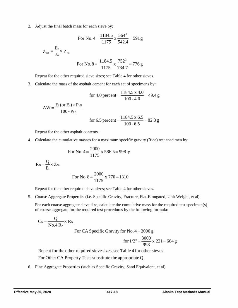
Effective May 30, 2020 417-18 Alaska Test Methods Manual
2. Adjust the final batch mass for each sieve by:
g 776 734.7
527 x 1175
1184.5 8 No.For
Z EZ
g 591 542.4564 x
11751184.5 4 No.For
2
Nia
Na
2
==
×=
==
iE
Repeat for the other required sieve sizes; see Table 4 for other sieves.
3. Calculate the mass of the asphalt cement for each set of specimens by:
g 82.3
6.5-1006.5 x 1184.5 percent 6.5for
P -100P )E(or E AW
g 49.4 4.0 - 100
4.0 x 1184.5 percent 4.0for
bN
bNai
==
×=
==
Repeat for the other asphalt contents.
4. Calculate the cumulative masses for a maximum specific gravity (Rice) test specimen by:
1310 770 x 11752000 8 No.For
Z EQ R
g 998 586.5 x 11752000 4 No.For
Nii
N
==
×=
==
Repeat for the other required sieve sizes; see Table 4 for other sieves.
5. Coarse Aggregate Properties (i.e. Specific Gravity, Fracture, Flat-Elongated, Unit Weight, et al)
For each coarse aggregate sieve size, calculate the cumulative mass for the required test specimen(s) of coarse aggregate for the required test procedures by the following formula:
Q. eappropriat thesubstitute TestsProperty CA Other For sieves.other for 4 Table see sizes, sieve requiredother for theRepeat
g 664 221 x 998
3000 1/2"for
g 3000 4 No.for Gravity SpecificCA For
R R No.4
Q C NN
N
==
=
×=
6. Fine Aggregate Properties (such as Specific Gravity, Sand Equivalent, et al)

Alaska Test Methods Manual 417-19 Effective May 30, 2020
For each fine aggregate sieve size, calculate the cumulative masses for the required specimens of fine aggregate specific gravity by the following formula:
( )
( )
( ) g 924.1 564 - 1115 x 564- 1175.0
1000 200 No.
forGravity SpecificFA For
g 307 564 - 752.0 x 564- 1175.0
1000 8 No.
Z- Z x Z- E
Q F
4iNi4ii
N
=
=
=
=
=
Repeat for the other required sieve sizes, See Table 4 for other sieves.
21. Calculations 1. Calculate the maximum specific gravity for each asphalt content as follows:
a. Calculate the effective specific gravity of the aggregate by:
2.745
1.0095.0
2.528100
5.0 - 100
GP
G100
P100G
b
b
mm
bse =
−=
−
−=
b. Calculate the maximum specific gravity for each asphalt content by:
contents.asphalt other for Repeat
2.568
009.10.4
745.24.0 100100 4.0%For
GP
GP 100100G
b
bN
se
bNmm =
+−
=+
−=
2. Calculate the percent air voids in total mix (VTM) for each asphalt content by:
6.4 x1002.568
2.403 2.568 4.0%For x100
GGGVTM
mm
mbmm =−
=−
=
3. Calculate the percent voids in mineral aggregate (VMA) for each asphalt content by:
a. Calculate the blended aggregate bulk specific gravity by:
2.689
2.65350
2.72750
100
GP...
GP
GP
100G
N
N
2
2
1
1sb =
+=
++=
b. Calculate the percent voids in mineral aggregate for each asphalt content by:
14.2 2.689
4.0) - (100 2.403100 4.0%For G
)P(100 G100VMAsb
bmb =−=−
−=
c. Calculate the percent voids filled (VFA) with asphalt for each asphalt content by:

Effective May 30, 2020 417-20 Alaska Test Methods Manual
55 14.2
6.4 - 14.2 x 100 4.0%For 100 ==−
×=VMA
VTMVMAVFA
4. Calculate the dust/asphalt ration for each asphalt content by:
a. Calculate the asphalt absorption by:
0.77 1.009 2.745 x 2.6892.689 - 2.745 100 4.0%For G
G GG - G100 P b
sesb
sbseba =
=
×=
b. Calculate the effective asphalt content for each asphalt content by:
( ) ( ) 3.3 4.0 - 100 1000.77 - 4.0 4.0%For P - 100
100P - P P b
babbe =
×
=
×
=
c. Calculate the dust/asphalt ratio by:
1.4 3.34.7 4.0%For
Pp200 D/A
be===
5. Stability:
Correct Stability values for each specimen that differs from the standard 63.5 mm (2.5") thickness by the following:
CS = S x t for Set 1, Specimen 1 = 3145 x 0.976 = 3070

Alaska Test Methods Manual 417-21 Effective May 30, 2020
Table 4 Cumulative Batch Masses for Example
Sieve Size Job Mix
Cumulative Mass g
Wash Post Correction Marshall Rice SG's
metric inches Formula Mass Wash ZNi ZNa RN CN
25 1 100 0 0
19 3\4 100 0 0 0 0 0 0
12.5 1\2 89 129 128.3 129.7 130.8 220.8 663.5
9.5 3\8 76 282 270.0 294.5 272.2 501.3 1506.7
4.75 #4 52 564 542.4 586.5 591.2 998.2 3000.0
2.36 #8 36 752 734.7 769.7 775.9 1310.1 311.4
1.18 #16 24 893 874.7 911.7 919.1 1551.8 552.6
0.6 #30 15 999 969.2 1029.7 1038.0 1752.7 753.1
0.3 #50 9 1069 1048.7 1089.7 1098.5 1854.8 855.1
0.15 #100 7 1093 1073.8 1112.5 1121.5 1893.7 893.9
0.075 #200 5.1 1115 1091.7 1138.8 1148.0 1938.4 938.5
-0.075 -200 0 1175 1175 1184.5 2000 1000

Effective May 30, 2020 417-22 Alaska Test Methods Manual
This page intentionally left blank.

Alaska Test Methods Manual 419-1 Effective May 30, 2020
ATM 419 Rutting Susceptibility using an Asphalt Pavement Analyzer
1. Scope This method describes a procedure for determining the rut susceptibility of hot mix asphalt using an Asphalt Pavement Analyzer (APA).
2. Apparatus
• Asphalt Pavement Analyzer (APA) – A thermostatically controlled device designed to test the rutting susceptibility of hot mix asphalt by applying repetitive linear loads to compacted test specimens through pressurized hoses.
o The APA shall be thermostatically controlled to maintain the test temperature and conditioning chamber at any set point between 30-60 ±1°C (85-140 ±1°F).
o The APA shall be capable of independently applying loads up to 450 N (100 lbf) to the three wheels. The loads shall be calibrated to the desired test load by a suitable device such as an external force transducer or proving ring.
o The pressure in the test hoses shall be adjustable and capable of maintaining pressure up to 830 kPa (120 psi).
o The APA shall be capable of testing six cylindrical specimens simultaneously.
o The APA shall have a programmable master cycle counter that can be preset to the desired number of cycles for a test. The APA shall be capable to automatically stopping the test at the completion of the programmed number of cycles.
• Balance or scale: Capacity sufficient for the principle sample mass, readable to 0.1 percent or 0.1 g of the total sample mass and meeting the requirements of AASHTO M 231.
• Mixing utensils (bowls, spoon, spatula)
• Ovens and hot plates thermostatically controlled to maintain the various required temperatures within ±3°C (5°F).
• Compaction device and molds.
3. Test Specimens Number of test specimens – A sample will consist of six 150 mm diameter × 75 mm (6 in diameter x 3 in) cylindrical specimens.
Production Mix
Samples of plant-produced mixtures shall be obtained in accordance with WAQTC FOP for AASHTO T 168. Samples shall be reduced to the appropriate test size in accordance with WAQTC FOP for AASHTO R 47 and compacted while the mixture is still hot. Reheating of loose plant mixture should be avoided.
Laboratory Prepared Mixtures
Mixture proportions will be batched in accordance to the desired Job Mix Formula. The required batch sizes are determined in accordance to ATM 417, Preparation of Aggregate and Preparation of Asphalt. The voids in total mix (VTM) target for the compacted specimens shall be 6.0 + 1.0 percent unless otherwise directed.
The temperature to which the asphalt binder must be heated to achieve a viscosity of 170 ± 20 cSt (0.170 + 0.020 Pa·s) or the mix design mixing temperature shall be the mixing temperature.

Effective May 30, 2020 419-2 Alaska Test Methods Manual
Prepare the mixture in accordance with ATM 417, Preparation of Mixtures and Mixture conditioning. The temperature to which the asphalt binder must be heated to achieve a viscosity of 290 ± 30 cSt (0.290 + 0.030 Pa·s) or the mix design compaction temperature shall be the compaction temperature.
Roadway Core Specimens
Roadway core specimens shall be 150 mm (6 in) outside diameter with all surfaces of the perimeter perpendicular to the surface of the core within 5 mm (3/16 in). Cores shall be trimmed with a wet masonry saw to a height of 75 ± 3 mm (3 ± 1/8 in). Final adjustment of the core to the top of the testing molds shall be done with Plaster of Paris.
4. Compaction of Specimens
Superpave Gyratory Compaction
Apparatus (see AASHTO T 312).
1. Compaction of the cylindrical specimens with the Superpave Gyratory Compactor will be performed in such a manner so that the target air void content of 6.0 ± 1.0 percent is obtained at the specified height of 75 ± 3 mm.
2. Remove the mold and base plate from the oven set at the compaction temperature. Place a paper disc in the bottom of the mold assembly.
3. Transfer the mixture to the mold with care to avoid segregation of the mixture.
4. Place the mold and mixture in the Superpave Gyratory Compactor and begin compaction as described in the compactor’s operation manual.
5. When the compaction procedure is completed, remove the mold and compacted specimen from the compactor. Extrude the specimen from the mold with care to avoid distorting the specimen until it is cooled.
6. Compacted specimens should be left at room temperature (about 25°C or 77°F) and allowed to cool overnight.
5. Determining the Voids Total Mix 1. Determine the bulk specific gravity of the test specimens in accordance with WAQTC FOP for AASHTO
T 166, Method A.
2. Determine the maximum specific gravity of the test mixture in accordance with WAQTC FOP for AASHTO T 209.
3. Determine the air void contents of the test specimens in accordance with AASHTO T 269.
6. Test Temperature The test temperature shall be 105°F unless otherwise directed.
7. Initial Measurements Place the rut depth measurement template over the specimen. Take initial measurements on three locations of each specimen. Record the measurement for each location to the nearest 0.01 mm.
8. Specimen Conditioning 1. Stabilize the testing chamber temperature at 105°F or as directed.
2. Place the test specimens into the testing molds and secure in the APA.

Alaska Test Methods Manual 419-3 Effective May 30, 2020
3. Push the sample holding tray in and secure. Close chamber doors.
4. Allow specimens to condition at the test temperature for 90 minutes.
5. Set PRESET COUNTER to 8000 cycles.
6. Start the testing. A complete test will take approximately 3.5 hours. At the end of the test cycle, the APA will stop.
7. Open the chamber doors, unlock and pull out the sample holding tray.
8. Remove specimens from the testing molds and take rut-depth measurements in the same manner as the Initial Measurements.
9. Calculations The rut depth at each location is determined by subtracting the final measurement from the initial measurement.
Determine the average rut depth for each specimen; use the average of all measurements to calculate the average rut depth.
The APA rut depth for the mixture is the average of six cylindrical specimens unless otherwise directed.
10. Report The test report shall include the following information:
• The laboratory name and date of test.
• The mixture type and description.
• The average rut depth to the nearest 0.1 mm.

Effective May 30, 2020 419-4 Alaska Test Methods Manual
This page intentionally left blank.

Alaska Test Methods Manual 420-1 Effective May 30, 2020
ATM 420 Abrasion of HMA Mix by the Prall Method
1. Scope These test methods (Method A and Method B) cover procedures for preparing and testing abrasion caused by studs on cylindrical bituminous specimens.).
2. References Method A originate from the Prall-method, but it is improved by comprehensive research work to meet an adequate design. According to Swedish research work the method correlates with abrasion in the field.
3. Definitions
• Method A measures the abrasion in cm³ on the top surface of a cylindrical specimen.
• Method B measures the abrasion in cm³ on the curved side of a cylindrical specimen.
4. Method A A cylindrical specimen having a diameter of 100±1 mm and a length of 30±1 mm is brought to a temperature of 5±1°C. Then, the specimen is worn during 15 minutes by 40 steel spheres. The loss of volume in cm³ is recorded and named abrasion value.
5. Apparatus 1. Abrasion apparatus according to fig. 1. -Stroke, 43 ± 1 mm. -Connection rod, 200 ± 5 mm.
2. Lid to abrasion apparatus, see fig 2. Quality: stainless steel, SS 2333, Bs 304S31, NF Z7CN18-09, DIN 1.4301, or better.
3. Steel clamp to fasten the lid on top of the machine adjustable by means of the screw at the top.
4. Spheres made of stainless steel according to ISO 3290-1975 with a diameter between 11.50 mm and 12.01 mm. The hardness expressed in HRC should be between 62 and 65
Note 1: The diameter of the balls can be checked quickly by passing them over parallel bars 11.50 mm apart.
5. O-ring made of rubber to protect the edges of the specimen, see fig. 1. Dimension: internal diameter 89.4 mm, diameter of cross section 6.3 mm. Rubber quality: NBR.
6. Rubber plate to be glued at the underside of the lid, see fig.2. Dimensions: diameter 90.0±1.0 mm, thickness 2.0±0.2 mm. Rubber quality: Neoprene.
7. O-ring made of rubber for the groove outside of the cylindrical part of the lid, see fig 2. Dimensions of rubber O-ring: internal diameter 90.0 mm, diameter of cross section 3.0 mm. Rubber quality: NBR
8. Water reservoir for cooling water and for adjustment of specimens temperature to 5±1 °C.
9. Balance: inaccuracy less than 0.1 g.
10. Water pump capacity more than 2.0 liter/minute.

Effective May 30, 2020 420-2 Alaska Test Methods Manual
Fig. 1. Abrasion apparatus, in principal
Rubber plate t=2,0 ± 0,2 mm
Fig 2. Lid
Cooling Water
O-ring
Specimen
Test Chamber
Connection rod 200 mm

Alaska Test Methods Manual 420-3 Effective May 30, 2020
6. Bituminous Mixtures for Testing 1. Laboratory made specimens and cores from the field.
2. Make at least 4 specimens of diameter 100±1 mm. Cut the specimens to a length of 30±1 mm. When cutting, the end surfaces should be even and parallel, as possible by standard cutting machines. When cutting one should avoid damaging the edges of the specimen.
3. Determine the Bulk density according to ATM 410.
7. Conditioning 1. Temper the specimens for 20±6 hours in water of temperature 5±1 °C.
2. Remove the specimen from the water, surface dry by blotting with a damp towel, and determine the weight.
8. Determination of Abrasion 1. Place the specimen in the test chamber with the cut end up-wards. Make sure that the specimen is tight to
the chamber-wall otherwise use tape around the specimen for a snug fit.
2. Place the O-ring on the specimen, and the steel spheres in the O-ring.
3. Fasten the lid onto the test chamber.
4. Adjust the amount of cooling water to 2±0.2 liter/minute.
5. Start the abrasion apparatus and let it work for 15 minutes ±10 seconds at 950±10 revolutions/minute.
6. Dismantle the apparatus. Remove the specimen from the apparatus and flush it in cold water. Surface dry by blotting with a damp towel, and determine the weight.
9. Calculation Calculate the abrasion value according to the formula below.
Abrasion value, Bd WW
Abr 21=
Where: Abr = abrasion value in cm³ ( 1 decimal) W1=weight of water stored specimen surface dry in air before abrasion(0.1g) W2=weight of water stored specimen surface dry in air after abrasion(0.1g) Bd = Bulk density of specimen according to 6.2 ( 3 decimals)
10. Report
• Report that the test has been carried out according to this method.
• Report individual as well as average values of Bulk density, with 3 decimals accuracy.
• Report individual values of Abrasion, with 1 decimal accuracy.
• Report average abrasion value, with no decimal.
• Determine the Bulk density according to ATM 410.

Effective May 30, 2020 420-4 Alaska Test Methods Manual
11. Precision The values should be accepted if the coefficient of variation of 4 specimens is less than 15%. Otherwise two extra specimens should be tested, and extremes should be expelled according to common statistical practice.
Coefficient of variation in percent:
Where: CV= Coefficient of Variation σ = Standard Deviation μ = Mean

Alaska Test Methods Manual 421-1 EffectiveMay 30, 2020
ATM 421 Sieve Analysis of Crushed Asphalt Base Course/Recycled Asphalt Material/Pavement
1. Scope
Sieve analysis determines the gradation or distribution of particle sizes within a given sample.
2. Apparatus
• Balance or scale: Accurate to 0.1 percent of the mass being determined or readable to 0.1 g, and meeting the requirements of AASHTO M 231
• Sieves: Meeting the requirements of ASTM E 11
• Containers and shovels
3. Procedure
1. Obtain a representative sample of the material, 18 kg (40 lb) minimum
2. Determine and record the total mass of the sample to the nearest 0.1 percent or 0.1 g.
3. Select sieves to furnish information required by the specifications. Nest the sieves in order of decreasing size from top to bottom. Place the nested sieves over a suitable container such as a 5 gallon bucket.
4. Place the sample on the top sieve.
5. Manually shake the sample until the material is completely separated
6. Any material retained on a sieve that is not crushed asphalt should be manually placed in the container.
7. Determine the cumulative mass passing each sieve to the nearest 0.1 percent or 0.1 g.
4. Calculations
5. Report
• Results on forms approved by the Department.
• Cumulative mass retained on each sieve.
• Cumulative percent retained on each sieve.
• Report percentages to the nearest 1 percent.

Effective May 30, 2020 421-2 Alaska Test Methods Manual
This page intentionally left blank.

Alaska Test Methods Manual 425-1 Effective May 30 2020
ATM 425 Interlayer Bond Strength between Pavement Layers
1. Scope This test method describes the procedure for determining the interlayer bond strength between two layers of asphalt mixtures or pavement layers by applying a load in the shearing mode.
This standard involves hazardous materials, operations and equipment. This standard does not purport to address all of the safety problems associated with its use. It is the responsibility of the agency to establish appropriate safety and health practices and to train the user of this standard prior to use. It is the responsibility of the user to consult the appropriate agency authority for and to practice and maintain the appropriate safety and health practices.
2. Apparatus
• Wet masonry saw
• Measuring device capable of measuring sample dimensions to the nearest 0.04 in. (1 mm).
• Air chamber or water bath capable of maintaining a temperature of 77±2oF (25±1oC)
• Loading machine (similar to Marshall Test Apparatus described in ATM 417, AASHTO T 245) capable of producing a minimum uniform vertical displacement of 0.1 in./min. (2.54 mm/min)
• Shear strength tester device (jig) capable of applying confining normal (compressive) load to a specimen. See Appendix A.
3. Test Specimens 1. Test specimens may be either laboratory-compacted asphalt mixtures or sampled from asphalt pavements.
Field core samples shall be not less than two inches and not greater than six inches in diameter.
2. Cores shall be taken full depth so that no prying action is needed to extract the cores from the pavement. Care shall be taken to avoid stress or damage to the interface during coring, handling, and transportation. If a core debonds at the interface of interest during the coring operation, acquire an additional core and make note of it on the coring report.
3. Mark the direction of traffic on the roadway surface before coring so that it can be identified on the core.
4. Identify the location of the interface layer with light color marker.
4. Sample Preparation and Conditioning 1. Measure the diameter of the specimen and the thickness of both layers to the nearest 0.04 in. (1 mm).
2. Condition the specimen in the air chamber or water bath at the test temperature of 77±2oF (25±1oC) for a minimum of 2 hours.
3. Once properly conditioned, place and orient the specimen on the shear tester so that the direction of traffic marked on the core is vertical. Place the top layer on the shearing side.
4. Load the specimen in such manner that the interlayer is located directly in the middle of the gap between the loading and reaction frames. The loading frame is the frame that can move up and down and the reaction frame is the stationary part of the apparatus.
5. Load the specimen by applying the displacement continuously at a rate of 0.1-in (2.54 mm) per minute until failure.
Effective May 30, 2020 425-2 Alaska Test Methods Manual
6. Record the ultimate load applied (Pmax) to the specimen to the nearest 1 lb. and the corresponding displacement to the nearest 0.02 in (0.5 mm).
5. Calculations Calculate the bond shear strength (Sb, psi) as follows:
Sb = Pmax / A
where:
Pmax = maximum load applied to the specimen (lb)
A = cross-sectional area of test specimen (in2) = ᴫ D2 / 4
D = average diameter of test specimen (in)
6. Report Report on a form approved by the Department the following:
1. Specimen number or identification, manufacturing or coring date, and test date.
2. Specimen dimensions: core diameter measurements, average diameter, thickness of the existing ‘old’ layer, and the thickness of the ‘new’ overlay layer to the nearest 0.04 in (1 mm).
3. Failure surface location: identify if failure occurred at the interface, in the existing ‘old’ layer or in the ‘new’ overlay layer.
4. The maximum load applied to the specimen to the nearest 1 lb.
5. The vertical displacement corresponding to the maximum load applied, to nearest 0.02 in (0.5 mm).
6. Bond shear strength to the nearest psi.
7. If applicable, report average and standard deviation bond strengths for a set of tested specimens or cores.
7. Appendix A Plan and cross sectional views of the testing apparatus: Refer to Figures 1 and 2 of AASHTO TP 114-18.
Standard Method of Test for Determining the Interlayer Shear Strength (ISS) of Asphalt Pavement Layers