ATISE: a miniature Fourier-transform spectro-imaging ...
9
HAL Id: hal-01401693 https://hal.archives-ouvertes.fr/hal-01401693 Submitted on 23 Nov 2016 HAL is a multi-disciplinary open access archive for the deposit and dissemination of sci- entific research documents, whether they are pub- lished or not. The documents may come from teaching and research institutions in France or abroad, or from public or private research centers. L’archive ouverte pluridisciplinaire HAL, est destinée au dépôt et à la diffusion de documents scientifiques de niveau recherche, publiés ou non, émanant des établissements d’enseignement et de recherche français ou étrangers, des laboratoires publics ou privés. ATISE: a miniature Fourier-transform spectro-imaging concept for surveying auroras and airglow monitoring from a 6/12U cubesat E. Le Coarer, M. Barthelemy, A. Vialatte, M. Prugniaux, G. Bourdarot, T. Sequies, P. Monsinjon, R. Puget, N. Guerineau To cite this version: E. Le Coarer, M. Barthelemy, A. Vialatte, M. Prugniaux, G. Bourdarot, et al.. ATISE: a miniature Fourier-transform spectro-imaging concept for surveying auroras and airglow monitoring from a 6/12U cubesat. ICSO 2016, Oct 2016, BIARRITZ, France. hal-01401693
Transcript of ATISE: a miniature Fourier-transform spectro-imaging ...
HAL Id: hal-01401693https://hal.archives-ouvertes.fr/hal-01401693
Submitted on 23 Nov 2016
HAL is a multi-disciplinary open accessarchive for the deposit and dissemination of sci-entific research documents, whether they are pub-lished or not. The documents may come fromteaching and research institutions in France orabroad, or from public or private research centers.
L’archive ouverte pluridisciplinaire HAL, estdestinée au dépôt et à la diffusion de documentsscientifiques de niveau recherche, publiés ou non,émanant des établissements d’enseignement et derecherche français ou étrangers, des laboratoirespublics ou privés.
ATISE: a miniature Fourier-transform spectro-imagingconcept for surveying auroras and airglow monitoring
from a 6/12U cubesatE. Le Coarer, M. Barthelemy, A. Vialatte, M. Prugniaux, G. Bourdarot, T.
Sequies, P. Monsinjon, R. Puget, N. Guerineau
To cite this version:E. Le Coarer, M. Barthelemy, A. Vialatte, M. Prugniaux, G. Bourdarot, et al.. ATISE: a miniatureFourier-transform spectro-imaging concept for surveying auroras and airglow monitoring from a 6/12Ucubesat. ICSO 2016, Oct 2016, BIARRITZ, France. �hal-01401693�
ICSO 2016 Biarritz, France
International Conference on Space Optics 18 - 21 October 2016
ATISE: A MINIATURE FOURIER-TRANSFORM SPECTRO-IMAGING CONCEPT
FOR SURVEYING AURORAS AND AIRGLOW MONITORING FROM A 6/12U
CUBESAT
E. Le Coarer1,3
, M. Barthelemy1,3
, A.Vialatte1,3
, M. Prugniaux3, G. Bourdarot
1,3, T. Sequies
3,4, P. Monsinjon
5 ,R.
Puget6 and N. Guerineau
2
1 Univ. Grenoble Alpes, CNRS, IPAG, F-38000 Grenoble, France.
2 ONERA, The French Aerospace Lab, F-91761 Palaiseau, France
3 CSUG, Centre Spatial Universitaire de Grenoble, 120 rue de la piscine, 38400 Saint-Martin-d'Hères, France
4 IUT, Institut Universitaire Technologique de Grenoble, UGA, BP 53 FR-38041 Grenoble cedex 9, France
5 Pyxalis Centr’Alp, 170 rue de chatagnon, BP 40034, 38346 Moirans Cedex-France
6 RESOLUTION Spectra Systems,13, chemin du Vieux Chêne, F-38240 Meylan-France
I. INTRODUCTION
The nanosatellite ATISE is a mission dedicated to the observation of the emission spectra of the upper
atmosphere (i.e. Airglow and Auroras) mainly related to both the solar UV flux and the precipitation of
suprathermal particles coming from the solar wind through the magnetosphere. ATISE will measure specifically
the auroral emissions, and the airglow (day- and night) in the spectral range between 380 and 900 nm at
altitudes between 100 and 350 km. The exposure time will be 1 second in auroral region and 20 s at low latitude
regions. The 5 year expected lifetime of this mission should cover almost a half of solar cycle (2 years nominal).
This instrument concept is based on an innovative miniaturized Fourier-transform spectrometer (FTS) allowing
simultaneous 1 Rayleigh sensitivity detection along six 1.5°x1° limb lines of sight. This 1-2kg payload
instrument is hosted in a 12U cubeSat where 6U are allocated to the payload and 6U to the plateform
subsystems. This represents a miniaturisation by a factor of 500 on weight and volume compared to previous
Arizona-GLO instrument for equivalent performances in the visible. The instrument is based on microSPOC
concept developed by ONERA and IPAG using one Fizeau interferometer per line of sight directly glued on top
of the half of a very sensitive CMOS Pyxalis HDPYX detector. Three detectors are necessary with a total
electrical consumption compatible with a 6U nanoSat. Each interferometer occupies a 1.4 M pixel part of
detector, each is placed on an image of the entrance pupil corresponding to a unique direction of the six lines of
sight, this in order to have a uniform illumination permitting good spectral Fourier reconstruction from fringes
created between the Fizeau plate and the detector itself. Despite a limited 8x6 cm telescope, this configuration
takes advantage of FTS multiplex effect and permits us to maximize the throughput and to integrate very faint
emission lines over a wide field of view even if the 1 second integrated signal is comparable to the detector
noise.
II. SCIENTIFIC GOALS AND MISSION REQUIEREMENTS
The science Requirements are :
- producing 6 contiguous 1.5°x1° field of view
- with a spectral domain between [350,900nm]. This allow to get the main part of the Vegard Kaplan N2
band in the lower part of the spectra and to get the O-844 nm line which is important in auroral region.
- The spectral resolution at 600nm must be lower than 1nm. Hence : R=λ/δλ=600 at 600nm. This allow
to disentangle the vibrational line of the molecular bands. The rotational structure is not reachable at
these spectral resolution.
- The detection threshold of each line must be 5 Rayleigh (1 R = 1.106 photons.cm-2.s-1) and the
sensitivity 1 R.

ICSO 2016 Biarritz, France
International Conference on Space Optics 18 - 21 October 2016
Fig. 1. Spectrum of the auroral simulator planeterrella (ref papier Jean) between 520 and 700 nm. The
resolution is around 1 nm. The spectrum of the aurora is somehow different since forbidden transitions also
appear in aurora and airglow mainly O1S at 557 nm and O
1D triplet at 630, 639 and 639 nm
II. INSTRUMENT PRINCIPLE AND DESCRIPTION
ATISE instrument is based on the MICROSPOC principle that was described in [1] by S. Rommeluère & al. It
is made of a two-wave interferometer glued in front of the detector. Rays coming from infinite are partly
reflected by the detector face and the substrate face as illustrated in fig. 3a make interferences detected by the
active layer of the detector. Contrarily to a classic optical instrument, the goal of ATISE is not to make an image
of each field of view, but to obtain an area which is uniformly illumined on each detector (those area on the
detector are called “plage de Fabry” [2]). To this end, the optical instrument can be viewed in two parts : first, a
system focuses the entire field of view on the focal plane. In those 6 areas, we Micro lenses divided then the
input light in 6 contiguous field. These micro lenses are positioned to project an image of the entrance pupil on
the detectors. Thus, we obtain on each detector uniformly illumined area of each field, which are perfectly
delimited, due to the pupil imaging through micro-lenses. As we will see further, the aperture (which is
characterized by the f-number : N=focal/diameter) of the micro-lenses is the fundamental parameter of the
design of this instrument. The aperture of the beam is yet strongly related to the nature of the spectrometer and
to the expected spectral resolution.
A µ-SPOC Fourier transform spectrometer is selected, in accordance with the mission specifications. This
miniaturised Fizeau interferometer use the principle of Fourier Transform spectroscopy to produce spectra, that
we are going to explain and illustrate in this paragraph.
ICSO 2016 Biarritz, France
International Conference on Space Optics 18 - 21 October 2016
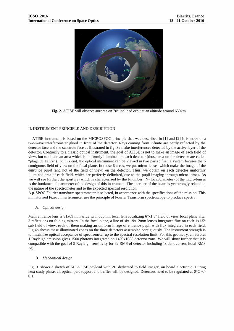
Fig. 2. ATISE will observe aurorae on 70° inclined orbit at an altitude around 650km
II. INSTRUMENT PRINCIPLE AND DESCRIPTION
ATISE instrument is based on the MICROSPOC principle that was described in [1] and [2] It is made of a
two-wave interferometer glued in front of the detector. Rays coming from infinite are partly reflected by the
detector face and the substrate face as illustrated in fig. 3a make interferences detected by the active layer of the
detector. Contrarily to a classic optical instrument, the goal of ATISE is not to make an image of each field of
view, but to obtain an area which is uniformly illumined on each detector (those area on the detector are called
“plage de Fabry”). To this end, the optical instrument can be viewed in two parts : first, a system focuses the 6
contiguous field of view on the focal plane. In those 6 areas, we put micro-lenses which make the image of the
entrance pupil (and not of the field of view) on the detector. Thus, we obtain on each detector uniformly
illumined area of each field, which are perfectly delimited, due to the pupil imaging through micro-lenses. As
we will see further, the aperture (which is characterized by the f-number : N=focal/diameter) of the micro-lenses
is the fundamental parameter of the design of this instrument. The aperture of the beam is yet strongly related to
the nature of the spectrometer and to the expected spectral resolution.
A µ-SPOC Fourier transform spectrometer is selected, in accordance with the specifications of the mission. This
miniaturised Fizeau interferometer use the principle of Fourier Transform spectroscopy to produce spectra.
A. Optical design
Main entrance lens is 81x69 mm wide with 650mm focal lens focalizing 6°x1.5° field of view focal plane after
3 reflections on folding mirrors. In the focal plane, a line of six 19x12mm lenses integrates flux on each 1x1.5°
sub field of view, each of them making an uniform image of entrance pupil with flux integrated in each field.
Fig 4b shows these illuminated zones on the three detectors assembled contiguously. The instrument strength is
to maximize optical acceptance of spectrometer up to the spectral resolution limit. For this geometry, an auroral
1 Rayleigh emission gives 1500 photons integrated on 1400x1088 detector zone. We will show further that it is
compatible with the goal of 5 Rayleigh sensitivity for 3e RMS of detector including 1s dark current (total RMS
3e).
B. Mechanical design
Fig. 3. shows a sketch of 6U ATISE payload with 2U dedicated to field imager, on board electronic. During
next study phase, all optical part support and baffles will be designed. Detectors need to be regulated at 0°C +/-
0.1.

ICSO 2016 Biarritz, France
International Conference on Space Optics 18 - 21 October 2016
Fig. 3. ATISE Mechanical implementation for optical test assembled with 6U plateform.
Fig. 4. a) ATISE optical schematic. b) Perspective view showing light distribution on each optical surface. The
optics forms an image of entrance pupil on detector which create an uniform illumination corresponding to one
of six line of sight.
C. Spectrometer design
The µ-SPOC spectrometer consists of a two-wave interferometer (a Fizeau interferometer) a semi-transparent
glass plate assembled on top of a detector. The hypothesis that only two waves interferes depending of the
reflectivity of the prism and the natural reflexion of the uncoated detector, as we will see further (contrast of
fringes). A monochromatic beam coming from the infinite on a substrate which has the height e reflects off the
detector and interferes with itself with an optical path difference (OPD) , where n is the optical index of the
substrate (Fig 5a). The reflectivity coefficient maximizing two waves detection is set between 25% and 50%
thus, the Fizeau finesse is comprised between 2 and 4. For glass plate part, a quaterwave single layer Ti02 gives
42% of reflexion as it has been design in [2]. The second face of interferometer is assumed by the natural
reflectivity of detector which is also 40%. Both reflectivity giving a fringe contrast of 66%. The 2808x1088
pixel detectors are divided in two zones of 1400*1088 pixels. On each zone, the fringes will be sampled along
the 1400 pixels fast axis giving possibility to reach R=700 spectral resolution at 365nm wavelength. The
detector pixel size is 10x10µm. the size of one Fizeau plate is 14x10mm. in front of each interferometer the
entrance pupil is imaged with 15x12mm microlens with 100mm focal then the interferometer is illuminated by
f/8 beam which is compatible with the R=600 spectral resolution at 600nm.

ICSO 2016 Biarritz, France
International Conference on Space Optics 18 - 21 October 2016
Fig. 5. a) SPOC principle : A semi-transparent plate is set on top of detector. Light coming from observed field
of view reflects both on semi-transparent plate and detector itself. Fringe pattern formed by interference is
measured by detector. Fourier transforms of this image gives the spectra corresponding to whole field of view
concern by this way. b) An HDPYX detector is divided in two zone with one interferometer by zone. 3
detectors permits us to select 6 lines of sight
III. SPOC PROTOTYPE AND FIRST LABORATORY TESTS
The first SPOC prototype composed by a 75mm plano-convex lens has been assembled with Pyxalis HDPYX
Sensor a 130µm spacer has been used to incline the plane in front of detector providing inclination compatible
with ATISE spectral resolution.
Fig. 6. left) Pyxalis HDPYX Sensor in BGA, Ceramic Ring configuration; right) tested SPOC configuration , a
60nm TiO2 layer has been deposited on plane of plano-convex lens. An optical fiber is set at focal plane of the
lens to obtain flat illumination.
Fig. 7. left) Observed Fringes of neon’s 703nm spectral line on SPOC; right) Observed fringes of whole
neon’spectra

ICSO 2016 Biarritz, France
International Conference on Space Optics 18 - 21 October 2016
Fig. 8. left) Reconstructed interferogram. Only the positive part of interferogram is measured.
right) reconstruction of neon’spectra surimposed to theoretical neon spectra.
II. PERFORMANCES VERIFICATIONS
A. Detector characterization
Two versions of electronics has been tested, the first one version is very compact but not yet optimized
regarding performances demanded by ATISE mission but this first prototype gives us these first encouraging
images with 24e readout noise. A second electronics used by detector manufacturer gives 2.5 e readout noise
which is the nominal readout noise without external perturbations and well stabilized alimentations. This
electronic cannot be used yet for these optical tests but will be available later. The functioning temperature has
been set to 20°C to avoid condensation. Some tests are under progress to determine the right functioning
temperature in order to have 3e in 1second exposure time i.e. less than 2e of dark current. The temperature of
the Fizeau and detector assembly will be set close to 0°C in satellite to fulfill the 3e noise specification in 1
second.
Fig. 9. left) HDPYX dark image in High gain configuration showing 4 ADU RMS corresponding to attended
2.5e read out noise.
In ATISE, the detector will be essentially used in high gain configuration with 10ke sample on 14bits ADC. The
full well capacity of pixel is 100ke can provide 120dB dynamics compatible with observation of very strong
solar events.
B. Spectra reconstruction
Mainly, three parameters are necessary to reconstruct the spectrum:
- Exact depth between Fizeau plate and detector reflection face principally the detector silicon interface
with metallic deposition for pixel’s electronic. This depth depends of wavelength because of TiO2
layer and passivation layer.
- Chromatic Pixel Photometric response depending of instrument transmission, Fizeau plate reflection
coefficient and detector quantum efficiency.
- Chromatic Fringe contrast which depends also of reflectivity of Fizeau Plate and detector reflectivity.

ICSO 2016 Biarritz, France
International Conference on Space Optics 18 - 21 October 2016
The calibration of these values for each pixel is obtained from two measurements:
- Observation of simple emission spectra such Neon lamp or high altitude night glow dominated by OI
630nm emission unresolved triplet at ATISE spectral resolution.
- Observation of broadband flat-field on integrating sphere, Moon or solar light reflecting on desert or
ocean surface
After this calibration, the 1 dimensional interferogram is obtained by averaging every pixel contribution on a
equidistant OPD distribution between optical contact (OPD=0) and maximum OPD.
C. Spectral resolution
The spectral resolution of Fourier Transform spectrometer depends only of the maximum sampled OPD. In our
case, the Fizeau sampling starts at minimum optical distance at mechanical contact between detector surface and
Fizeau plate surface. This minimum distance is around 1 micron according to passivation layer depth of
detector. This mean that we don’t measure the first fringe but this is not necessary for emission line spectra such
aurorae. The maximum OPD distance is given by the depth of spacer set on the opposite side i.e. the angle of
interferometer is 0.5°. This angle corresponds to a Shannon sampling of 700 fringes at 365nm which is the
shorter wavelength.. If this medium is vacuum, this depth is 125µm if this medium is optical glue, n=1.5 and
the depth is 82µm. SPOC sample one side interferogram, the full spectral resolution is attained when the
interferogram is symmetrized before Fourier transform or to use directly the Cosine transforms. In two cases,
the knowledge of absolute value of OPD is required. The pattern of neon’s fringes of fig. 6. is sufficient to
determine absolute OPD values. The spectral resolution is 1.5nm at 703 nm corresponds to the ATISE goal.
D. Low illumination Sensitivity
ATISE will observe at limb integrating aurora oval from the side as shown in the Fig. 2. The expected
brightness is estimated to be 10kR i.e. 10^8 photons/s on each line of sight. This represents 5e6 photon on 1s
exposure on detector. A very first laboratory experiment has been made observing an argon and neon discharged
lamp which represents similar emission lines. The readout electronic is not yet optimized and the readout noise
has been actually measured at 25e , this means that we has obtain similar results introducing 5e7 photons in the
systems.
Fig. 10. left) Under low flux illumination corresponding to flux receive in 1s exposure of aurora .Fringes visible
on fig. 7 are not visible but are sufficient to build a usable spectra after Fourier transforms.
Fainter distinguishable lines represent 50R that is equivalent to the ATISE’s 5R requirement according the
actual experimental noise excess that will be corrected during next study phases.
IV. CONCLUSIONS
ATISE is an innovative spectrometer taking advantage of detector progress. It permits us to design small and
powerful instruments to surveying aurorae and upper atmosphere airglows. Strengths of this concept if its ability
to integrate very faint diffuse emissions under a large solid angle contrary to slit spectrometers. The new
HDPYX CMOS detector has an exceptional dynamics especially optimized for Fourier spectrometry with low
readout noise. It is well adapted to ATISE to follow large dynamic events without saturations. The uncoated
detector is well adapted to play a role of semi-transparent mirror , we exploit this feature to win a 40% of
ICSO 2016 Biarritz, France
International Conference on Space Optics 18 - 21 October 2016
transmission. The measurements accuracy don’t depend of optics stability but only of the stability of the
assembly of Fizeau interferometer to detector which not requires 0.1° thermal regulation on a very small volume
and weight.
AKNOWLEDGMENTS
We would acknowledge the FOCUS labex which funds first prototype and supports the SPOC project. ATISE
project is developed in collaboration with Zelenograd university and the University Space Center in Toulouse.
50 students has worked for ATISE project in Grenoble University Space Centre which is funded by Grenoble
INP and UGA and Rhone-Alpes Région. Many thanks to CNES-JANUS programs and Michel Moulin.
REFERENCES
[1] S. Rommeluère, N. Guérineau, R. Haidar, J. Deschamps, E. De Borniol, A. Million, J-P Chamonal and G.
Destefanis, “Infrared focal plane array with a built-in stationary Fourier-transform spectrometer: basic concepts”, Opt. Lett. 33, pp 1062-1064 (2008) G. Eason, B. Noble, and I.N. Sneddon, “On certain integrals of Lipschitz-Hankel type involving products of Bessel functions,” Phil. Trans.. Roy. Soc. London, vol. A247, pp. 529-551, April 1955.
[2] E. le Coarer, B. Schmitt, N. Guerineau, G. Martin, S. Rommeluere, Y. Ferrec, F. Thomas , F. de la Barrière, Th. Diard, “SWIFTS-LA : An Unprecedently Small Static Imaging FT Spectrometer” Proceedings of the International Conference on Space Optics, (2014).