
Aticulo 2 Timed CPNversion Final
9
1 Modeling, analysis and simulation of an automated plates manufacturing system using Timed Coloured Petri Nets Angel Alberto Castro † , Jose Fernando Jimenez ‡. Department of Electrical and Electronics Enginnering, Universidad de los Andes, Bogota. Colombia. Abstract —Thi s paper prese nts the model ing, simulati on and analys is of a thr ee types of pla tes manufa cturin g sys tem wit h timed col our ed Pe tri nets (CPNs) . The main goal is to cop e the pr obl em of ach ie vin g the thr ee pr oce sse s in a concur re nt manner without conflict in the use of shared resources, that is, to achive a compact model for a flexible manufacturing system. At first we obtain an ordinary model by means of the union of the subnets, each of them representing an operation of the system and then is shown the complet ed Petri net model simulated in WoPeD [1]. That model is folded in a coloured Petri net in order to simpli fy the model to mak e the dec isi on mak ing eas ie r . In the coloured Petri net we add the failure states and determine certains parameters of the system and thus avoid conflicts, verify the liveness and limitation of the system and obtain a model for contr ol all the proces s and improv e the behavi or of the plant. Finally we assign possibles transition times to the model to find the time accumulated vector for the processes in the model, using this ve ctor it is pos sib le loc ate the bes t sys tem seq uen ce . The timed CPN has been simulated in CPN tools [ 2]. Index Terms—syn chr onize d Pet ri net, Au tonomo us and Non autonomous Petri nets, flexible manufacturing system, task con- currency, timed coloured Petri net, performance evaluation. I. I NTRODUCTION N OW ADA YS the produ ctio n syste m is focu sed on ob- tai nin g the lar ges t number of pro duc ts in the sho rtest ti me. So, it is normal the ri se of fle xi bl e ma nufa ct ur ing systems FMS that allow to connect several work stations to comp lete a spec ific job . This structur e allo ws manu fact ure multiples products concurrently given to the system flexibility and adaptability. The discrete mode of operation of an automated manufac- turing system makes that usual control theory do not apply because there are not a continuos system that can be modeled by a differential equation. Discrete event systems encompass a wide variety of physical systems that arise in technology . These include manufacturing systems, traffic systems, logistic systems, database management systems, communication pro- tocol, and data communication networks [ 3]. As mentioned by Cassandras [4] the two main modeling for- malisms of discrete event systems DES to represent languages are automata and Petri nets PN. Like an automaton, a Petri net † Angel Castro is with the Department of Electrical Enginnering, Univer- sidad de los Andes, Bogota, Colombia, e-mail: [email protected]. ‡ Fernando Jimenez is with the Department of Electrical Enginnering, Uni- versidad de los Andes, Bogota, Colombia e-mail: [email protected]. is a device that manipulates events according to certain rules allowing modelling systems as a parallel evolution with several processes in cooperation, with a common goal. In a PN, the places represent resources such as machines, mobi l robo ts, buf fers , etc. A tran siti on firing repres ents an acti vity , begi nning and endi ng with two cons ecuti ve ev ents. The transition is fired when there are enought resources in the places. PN models fall into one of two classes: timed PN models and untimed PN models [5]. A timed PN of an FMS captures the actual physical behavior of the FMS by assuming specific durations for various activities in the FMS. An untimed PN model of the FMS does not associate any times with the ac- tivities. Coloured PN is a graphical language for constructing models of concurrent systems and analysing their properties [8], [13]. CPN models are formal, in the sense that the CPN modelling language has a mathematical definition of both its syntax and its semantics. Such models can be manipulated by a computer tool and can be used to verify system properties, i.e., prove that certain desired properties are fullfilled or that certain undesired properties are guaranteed to be avoided [ 13], [8]. To obtain high quality and low operating costs of the system, we must ensure simple and flexible configuration of the system and short time periods to solve the problem of planning and cont rol [10], for this reaso n the simulat ion of ti med CPNs is an excellent tool when we are designing, controlling and analysing some system. II. GENERAL DESCRIPTION A. Manufacturing System The manufacturing system is an extension of the presented in the paper by Jimenez and Castro [6], and it contains three conc urre nt flows of job processe s that make three diffe rent types of plates at the same time and exploits the use of shared resources. Process one produces the first type of plate, process two produces the second type of plate and the process three produces the third type of plate. The first type is a blank plate, the second is a pa inte d pl at e, and the thir d one is a pl ate engraved. To realize the operations of painting and engraving were added two aditional machines or resources to system, i.e. a robot spray painting and a press machine. The tabl e I shown the syst em’s resources, its resp ecti ve label s and the resources used by each process.
-
Upload
angel-alberto-castro-lancheros -
Category
Documents
-
view
221 -
download
0
Transcript of Aticulo 2 Timed CPNversion Final

7/29/2019 Aticulo 2 Timed CPNversion Final
http://slidepdf.com/reader/full/aticulo-2-timed-cpnversion-final 1/9
1
Modeling, analysis and simulation of an automated
plates manufacturing system using
Timed Coloured Petri Nets
Angel Alberto Castro † , Jose Fernando Jimenez ‡.Department of Electrical and Electronics Enginnering,
Universidad de los Andes, Bogota. Colombia.
Abstract—This paper presents the modeling, simulation andanalysis of a three types of plates manufacturing system withtimed coloured Petri nets (CPNs). The main goal is to copethe problem of achieving the three processes in a concurrentmanner without conflict in the use of shared resources, that is,to achive a compact model for a flexible manufacturing system.At first we obtain an ordinary model by means of the union of the subnets, each of them representing an operation of the systemand then is shown the completed Petri net model simulated inWoPeD [1]. That model is folded in a coloured Petri net in orderto simplify the model to make the decision making easier. Inthe coloured Petri net we add the failure states and determinecertains parameters of the system and thus avoid conflicts, verifythe liveness and limitation of the system and obtain a model forcontrol all the process and improve the behavior of the plant.Finally we assign possibles transition times to the model to findthe time accumulated vector for the processes in the model, usingthis vector it is possible locate the best system sequence. Thetimed CPN has been simulated in CPN tools [2].
Index Terms—synchronized Petri net, Autonomous and Nonautonomous Petri nets, flexible manufacturing system, task con-currency, timed coloured Petri net, performance evaluation.
I. INTRODUCTION
NOWADAYS the production system is focused on ob-
taining the largest number of products in the shortest
time. So, it is normal the rise of flexible manufacturing
systems FMS that allow to connect several work stations to
complete a specific job. This structure allows manufacture
multiples products concurrently given to the system flexibility
and adaptability.
The discrete mode of operation of an automated manufac-
turing system makes that usual control theory do not apply
because there are not a continuos system that can be modeled
by a differential equation. Discrete event systems encompassa wide variety of physical systems that arise in technology .
These include manufacturing systems, traffic systems, logistic
systems, database management systems, communication pro-
tocol, and data communication networks [3].
As mentioned by Cassandras [4] the two main modeling for-
malisms of discrete event systems DES to represent languages
are automata and Petri nets PN. Like an automaton, a Petri net
† Angel Castro is with the Department of Electrical Enginnering, Univer-sidad de los Andes, Bogota, Colombia, e-mail: [email protected].
‡ Fernando Jimenez is with the Department of Electrical Enginnering, Uni-versidad de los Andes, Bogota, Colombia e-mail: [email protected].
is a device that manipulates events according to certain rules
allowing modelling systems as a parallel evolution with several
processes in cooperation, with a common goal.
In a PN, the places represent resources such as machines,
mobil robots, buffers, etc. A transition firing represents an
activity, beginning and ending with two consecutive events.
The transition is fired when there are enought resources in theplaces.
PN models fall into one of two classes: timed PN models
and untimed PN models [5]. A timed PN of an FMS captures
the actual physical behavior of the FMS by assuming specific
durations for various activities in the FMS. An untimed PN
model of the FMS does not associate any times with the ac-
tivities. Coloured PN is a graphical language for constructing
models of concurrent systems and analysing their properties
[8], [13]. CPN models are formal, in the sense that the CPN
modelling language has a mathematical definition of both its
syntax and its semantics. Such models can be manipulated by
a computer tool and can be used to verify system properties,
i.e., prove that certain desired properties are fullfilled or thatcertain undesired properties are guaranteed to be avoided [13],
[8].
To obtain high quality and low operating costs of the system,
we must ensure simple and flexible configuration of the system
and short time periods to solve the problem of planning and
control [10], for this reason the simulation of timed CPNs
is an excellent tool when we are designing, controlling and
analysing some system.
I I . GENERAL DESCRIPTION
A. Manufacturing System
The manufacturing system is an extension of the presented
in the paper by Jimenez and Castro [6], and it contains threeconcurrent flows of job processes that make three different
types of plates at the same time and exploits the use of shared
resources. Process one produces the first type of plate, process
two produces the second type of plate and the process three
produces the third type of plate. The first type is a blank plate,
the second is a painted plate, and the third one is a plate
engraved. To realize the operations of painting and engraving
were added two aditional machines or resources to system, i.e.
a robot spray painting and a press machine. The
table I shown the system’s resources, its respective labels
and the resources used by each process.
7/29/2019 Aticulo 2 Timed CPNversion Final
http://slidepdf.com/reader/full/aticulo-2-timed-cpnversion-final 2/9
2
Table ISYSTEM’S RESOURCES
LABEL RESOURCEPROCESS TYPE
I II III
M1 Conveyor Belt • • •
M2 Robot Arm 1 • • •
M3 Robot Arm 2 • • •
M4 Quarter Turn Table • • •
M5 Robot Spray Painting •
M6 Press Machine •
M7 Buffer 1 •
M8 Buffer 2 •
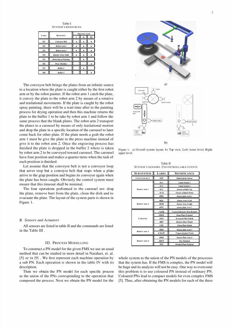
The conveyor belt brings the plates from an infinite source
to a location where the plate is caught either by the first robot
arm or by the robot painter. If the robot arm 1 catch the plate,
it convey the plate to the robot arm 2 by means of a rotative
and traslational movements. If the plate is caught by the robot
spray painting, there will be a wait time after to the painting
process for drying operation and then this machine returns the
plate to the buffer 1 to be take by robot arm 1 and follow the
same process that the blank plates. The robot arm 2 transport
the plates to a carousel by means of only traslational motion
and drop the plate in a specific location of the carousel to later
come back for other plate. If the plate needs a grab the robot
arm 1 must be give the plate to the press machine instead of
give it to the robot arm 2. Once the engraving process has
finished the plate is dropped in the buffer 2 where is taken
by robot arm 2 to be conveyed toward carousel. The carousel
have four position and makes a quarter turns when the task of
each position is finished.
Let assume that the conveyor belt is not a conveyor loop
that never stop but a conveyor belt that stops when a plate
arrive to the grap position and begins its conveyor again when
the plate has been caught. Obviusly the control system must
ensure that this timeout shall be minimal.
The four operations performed in the carousel are: drop
the plate, remove burr from the plate, clean the dish and to
evacuate the plate. The layout of the system parts is shown in
Figure 1.
B. Sensors and Actuators
All sensors are listed in table II and the commands are listed
in the Table III .
III . PROCESS MODELLING
To construct a PN model for the given FMS we use an usual
method that can be studied in more detail in Narahari, et. al.
[5] or in [9] . We first represent each machine operation by
a sub PN. Each operation is shown in the table IV with its
description.
Then we obtain the PN model for each specific process
as the union of the PNs corresponding to the operation that
composed the process. Next we obtain the PN model for the
a)
b)
Figure 1. a) Overall system layout. b) Top view. Left: lower level, Right:upper level.
Table IISYSTEM’S SENSORS. UNCONTROLLABLE EVENTS
SUB SYSTEM LABEL SIGNIFICANCE
CONVEYOR BELT SOP Optical pl ate Sensor
ROBOT ARM 1
FC1 Limit Switch 1
FC2 Limit Switch 2
SCU Sensor cylinder Up
SC D S en sor cyl ind er D own
SPB1 Sensor plate Arm 1
ROBOT ARM 2
SB2L Sensor Arm 2 Left
SB2R Sensor Arm 2 ri ght
SPB2 sensor plate Arm 2
CAROUSEL
CQTR Carousel Quarter Turn Rotated
DRDF Drop Plate Fi nished
ED F Eva cua te P lat e F ini sh
RBF Remove Burr Finish
CDF Clean Plate Finish
ROBOT ARM 3 SPB3 Sensor plate Arm 3 E NG PF E ng rav ed p la te F in is h
ROBOT ARM 4
SPB4 Sensor Plate Arm 4
DRYF Dry Finished
PP F Pai nted Pl ate Fi ni sh ed
whole system as the union of the PN models of the processes
that the system has. If the FMS is complex, the PN model will
be huge and its analysis will not be easy. One way to overcome
this problem is to use coloured PN instead of ordinary PN.
Coloured PNs lead to compact models for even complex FMS
[5]. Thus, after obtaining the PN models for each of the three

7/29/2019 Aticulo 2 Timed CPNversion Final
http://slidepdf.com/reader/full/aticulo-2-timed-cpnversion-final 3/9
3
Table IIISYSTEM’S COMMANDS. CONTROLLABLE EVENTS
SUB SYSTEM LABEL SIGNIFICANCE
CONVEYOR BELTCBAC Conveyor bel t advance command
C BS C C onv eyo r b el t s to p c om ma nd
ROBOT ARM 1
DCC Down Cylinder Command
UCC Up cylinder Command
DAC Down Arm command
UAC Up Arm Command
GD CA 1 Gr ip p lat e co mm an d A rm 1
GDCA1FB1 Grip plate command Arm 1 from Buffer 1
ROBOT ARM 2
A2LC Arm 2 left command
A2RC Arm 2 right command
GD CA 2 Gr ip p lat e co mm an d A rm 2
GDCA2FB2 Grip plate command Arm 2 from Buffer 2
CAROUSEL
CQTC Carousel Quart er Turn Command
RBC Remove Burr Command
CDC Clean plate Command
EDC Evacuate pl ate Command
DRDC Drop plate Command
ROBOT ARM 3
GD CA 3 Gr ip P lat e C omm an d A rm 3
EN GP C E ng rav ing Pl ate Com mand
DWPB 2 Dow nl oad Pl ate Buf fer 2
ROBOT ARM 4GD CA 4 Gr ip P lat e C omm an d A rm 4
DWPB 1 Dow nl oad Pl ate Buf fer 1
Table IVSYSTEM’S OPERATIONS
OPERATION DESCRIPTION
O1 transport plate by the conveyor belt
O2 Take the plate by the robot arm 1 and upload it
O3 Take the plate by the spray robot painting, paint it and return it
O4 Take the plate by robot arm 2 and deposit on the carousel
O5 Get down the arm robot 1
O6 move the robot arm 2 to the right
O7 Take the plate by the press machine, engraved it and return it to the robot arm 2
O8 Carry out the process involved in the carousel
processes we can folded that PNs in a coloured petri net with
tokens of three colours.
Like there are three processes running in the same system,
with the same resources we must stablish for each process its
respective operation sequence, Table V.
Table VSEQUENCE OF OPERATIONS
PROCESS SEQUENCE OF OPERATIONS
I O1-O2-O4-(O5||O6||O8)
II O1-O3-O2-O4-(O5||O6||O8)
III O1-O2-O7-O4-(O5||O6||O8)
A. Operations Sub-Petri nets
From Table IV we have eight basic operations. Below are
explained these operations and now are shown the respectives
sub PNs which have been modeled following the structure of
the figure 2 [9]
1) O1: Transport the plate by the conveyor belt: For this
operation we have the places and transitions listed in table
VI. Place 1 stablish the condition of a plate is ready to enter
Figure 2. Generic Model of an Operation
the operation. P2 corresponds to move the conveyor belt. P3
indicates that the belt is stopped and the plate is in position
to be caught. P4 can be seen as the execution of the operation
“up Arm 1” and P40 as “painting and drying the plate” . P5
indicates that the plate has finished the operation “Up Arm”,
i.e., the plate has been caught by the robot arm1 and is ready
for the next operation. P41 indicates that the plate is painted
and dry. P6 indicates that the resource M1 is available. P0
ensure that come one plate at a time. The sub petri net is
shown in figure 3.
Table VIPLACES AND TRANSITIONS FOR THE OPERATION 1
PLACE DESCRIPTION
P1 plate ready and waits
P2 moving conveyor belt
P3 conveyor belt stopped
P4 taking and uploading the plate
P5 End of operation P4
P6 Resource M1 available
P40 taking and painting the plate
P41 End of operation P40
P0 condition plate feeder
TRANSITION DESCRIPTION
T1 CBAC
T2 SOP
T3 GDCA1
T4 SPB1
T40 GDCA4
T41 SPB4
Figure 3. Transport operation by conveyor belt
2) O2: Take the plate by the robot arm 1 and upload it:
For this operation we have the places and transitions listed
in table VII. This petri net uses the resource M2 (robot arm

7/29/2019 Aticulo 2 Timed CPNversion Final
http://slidepdf.com/reader/full/aticulo-2-timed-cpnversion-final 4/9
4
1) to carry out the operation 2 (O2). The resource is released
when the plate is taken either by robot arm 2 or by press
machine. P3 and P19 or P44 and P19 must be marked to start
the operation. P4 to P11 can be seen as the execution of carry
up the plate that has been taking from the conveyor. P44 to
P11 can be seen as the execution of carry up the plate that has
been taking from the Buffer 1.. P19 indicates that the resource
M2 is free. The sub petri net is shown in figure 4.
Table VIIPLACES AND TRANSITIONS FOR THE OPERATION 2
PLACE DESCRIPTION
P3 conveyor belt stopped
P4 taking the plate by arm 1 from the conveyor
P44 plate ready in Buffer 1
P45 taking the plate by arm 1 from the Buffer 1
P5 plate gripped by the arm 1 ready for operation 2
P7 moving up arm 1
P8 moving up cylinder 1
P9 moving up cylinder 1
P10 moving up arm 1
P11 plate ready for to be taken
P12 Taking plate by robot arm 2
P13 plate took by arm 2
P14 Taking plate by press machine
P15 plate took by press machine
P19 resource M2 available
TRANSITION DESCRIPTION
T3 GDCA1
T4 SPB1
T443 GDCA1FB1
T444 SPB1
T5 UAC
T6 SBU
T7 SCU
T8 UCC
T9 SCU
T10 SBU
T11 GDCA2
T12 SPB2
T13 GDCA3
T14 SPB3
Figure 4. Taking plate operation by the robot arm 1 and upload it
3) O4: Grip the plate by the robot arm 2 and deposit it on
carousel: For this operation we have the places and transitions
listed in table VIII. This petri net uses the resource M3 (robot
arm 2) to carry the plate from the robot arm 1 or from the
Buffer 2 to carousel. The resource is released when the plate
is dropped on the table. The sub petri net is shown in figure
5.
Table VIIIPLACES AND TRANSITIONS FOR THE OPERATION 4
PLACE DESCRIPTION
P11 plate in conveyor ready for be take by the robot arm 2
P12 Taking plate by robot arm 2
P63 plate ready in Buffer 2
P64 taking plate by arm 2 from the Buffer 2
P13 plate took by arm 2
P21 moving arm 2 to the left
P22 arm 2 in the left
P23 arm 2 is depositing the plate
P24 plate on the carousel
P25 resource M3 available
TRANSITION DESCRIPTION
T11 GDCA2
T12 SPB2
T631 GDCA2FB2
T632 SPB2
T20 A2LC
T21 SB2L
T22 DRDC
T23 DRDF
Figure 5. Grip plate operation by the robot arm 2 and deposit it on carousel
4) O5: Get down the arm robot 1: For this operation we
have the places and transitions listed in table IX. This petri
net uses the resource M2 (robot arm 1) to down the robot arm
1. The resource is released when the arm 1 is positioned in
the down position. The sub petri net is shown in figure 6.a.
(P56.P18) collects P56 to P18 its simplified net is shown in
figure 6.b.
5) O3: Take the plate by the spray robot painting, paint it and return the painted plate : For this operation we have the
places and transitions listed in table X. This petri net uses the
resource M5 (robot spray painting) to carry the plate from the
conveyor belt to a location to paint it and then returns it. The
resource is released when the plate is dropped on the Buffer
1. The sub petri net is shown in figure 7.6) O6: move the robot arm 2 to the right: For this operation
we have the places and transitions listed in table XI. This petri
net uses the resource M3 (robot arm 2) and its work is to put
this resource to the right. The resource is released when the
arm is in the right. The sub petri net is shown in figure 8.

7/29/2019 Aticulo 2 Timed CPNversion Final
http://slidepdf.com/reader/full/aticulo-2-timed-cpnversion-final 5/9
5
Table IXPLACES AND TRANSITIONS FOR THE OPERATION 5
PLACE DESCRIPTION
P13 plate took by arm 2
P15 plate took by press machine
P19 resource M2 available
P14 moving down arm 1
P15 moving down cylinder 1
P16 moving down cylinder 1
P17 moving down arm 1
P18 arm 1 and cylinder 1 get down
TRANSITION DESCRIPTION
T15 SPB3
T16 SPB2
T17 DCC
T18 SCD
T19 SBD
T20 DAC
T21 SBD
T22 SCD
T111 ’1’
Figure 6. Get down arm robot 1 operation
7) O7: Take the plate by the press machine, engraved it
and return it to the robot arm 2: For this operation we have
the places and transitions listed in table XII. This petri net
uses the resource M3 (robot arm 2) and its work is to put this
resource to the right. The resource is released when the arm
is in the right. The sub petri net is shown in figure 9.
8) O8: Carry out the process involved in the carousel: For
this operation we have the places and transitions listed in table
Table XPLACES AND TRANSITIONS FOR THE OPERATION 3
PLACE DESCRIPTION
P3 conveyor belt stopped
P40 take plate by painting arm
P41 painting plate
P42 drying plate
P43 dowloading plate in buffer 1
P44 plate in Buffer 1
P50 resource M5 available
TRANSITION DESCRIPTION
T2 SOP
T40 GDCA4
T41 SPB4
T42 PPF
T43 DRYF
T44 DWPB1
Figure 7. Operation: Take the plate by the spray robot painting, paint it andreturn the painted plate
Table XIPLACES AND TRANSITIONS FOR THE OPERATION 6
PLACE DESCRIPTION
P24 plate on the carousel
P25 resource M3 available
P26 moving robot arm 2 to the right
P27 robot arm 2 in right position
TRANSITION DESCRIPTION
T23 DRDC
T24 A2RC
T25 SB2R
XIII. This petri net uses the resource M4 (quarter turn table).
The sub petri net is shown in figure 10.
IV. ANALYSIS
To achieve an analysis of the Petri net we make the union of
the operations and we carry out a simulation over the ordinary
PN having in mind what token type can hold in a place. The
simulation was made in the software woPed [1]. The model
thus obtained have 37 places and 31 transitions and are found
3 estructural conflicts. The ordinary PN is shown in Figure
11.
Figure 8. Operation: move the robot arm 2 to the right

7/29/2019 Aticulo 2 Timed CPNversion Final
http://slidepdf.com/reader/full/aticulo-2-timed-cpnversion-final 6/9
6
Table XIIPLACES AND TRANSITIONS FOR THE OPERATION 7
PLACE DESCRIPTION
P11 plate ready for be take by the press machine
P14 taking plate by press machine
P15 plate took by press machine
P61 engraving plate
P62 dowloading plate in buffer 2
P63 plate in Buffer 2
P60 resource M6 available
TRANSITION DESCRIPTION
T13 GDCA3
T14 SPB3
T61 ENGPC
T62 ENGPF
T63 DWPB2
Figure 9. Operation: Take the plate by the press machine, engraved it andreturn it to the robot arm 2
A. Estructural conflicts and blocking
The first conflict arises in the place P13, this place indicates
the state in which the arm robot 2 has taken the plate. That
place is an input of the transitions T20 and T16. T20 leads
to the operation of carrying the plate to the carousel and T16
leads to the operation of lowering the arm 1. The conflict is
that it is no possible to execute concurrently the two operations
because the enabling of one transition involves deactivate the
Table XIIIPLACES AND TRANSITIONS FOR THE OPERATION 8
PLACE DESCRIPTION
P24 plate on the carousel
P28 resource M4 available
P29 turning the quarter turn table
P30 removing burr
P31 burr removed
P32 cleaning the plate
P33 plate cleaned
P34 evacuating plate
P35 plate evacuated
P36 READY PLATES
TRANSITION DESCRIPTION
T23 DRDF
T26 CQTC
T27 CQTR
T28 RBF
T29 CDF
T30 EDF
Figure 10. Operation: Carry out the process involved in the carousel
other transition.
The second structural conflict ocurrs in the place P24 which
indicates that the plate has been dropped on the carousel. P24
is an input place to transitions T24 and T26. T24 leads to the
operation of returning the robot arm 2 to the right position
and T26 leads to turn the quarter turn table. In this case, the
conflict makes that if the carousel is turned, it is disable the
process of return the robot arm 2 to the right, generating a
block when other plate should be collected by robot arm 2.
On the other hand, if the arm robot is returned, the carousel
can not be turned producing a block when the next plate should
be dropped on the carousel because that position is occupied.
The third estructural conflict is produced in the place P15
which indicates that the plate has been caught by the pressmachine. That place is an input place of T61 and T15. T61
leads to the engraving the plate and T15 to get down the robot
arm 1. The conflict makes that, if is performed the operation of
engraving, will not lower the robot arm 1 causing a block when
the next plate in the conveyor belt or in the buffer 1 should
be caught by the arm 1. If instead the robot arm is lowered,
a plate will be stuck in the press machine and therefore could
not reuse that resource.
1) Solution of conflicts: Because the structural conflicts
enabling one transition while disabling the other, the solution
proposed in this paper is to merge the two transitions. Thus,
when a token reaches the place and the transition will be fired,
the two operation will be performed concurrently.That solution implies restrictions over the system because
the respective transitions not only have as an input place the
common place but also others places that are not commons.
In this system, the restrictions are the following:
For the first conflict, merging T16 and T20 arise a transition
that leads to get down the robot arm 1 and to carry the plate
to the carousel. That transition have as an input place also P19
(represent resource robot arm 1 is free), then
• to carry the plate to the carousel is necessary that the
robot arm 1 is available
In the second structural conflict merging T24 and T26 results
7/29/2019 Aticulo 2 Timed CPNversion Final
http://slidepdf.com/reader/full/aticulo-2-timed-cpnversion-final 7/9
7
a transition that is enable not only by the place P24 but also
by P28 (resource: carousel) and P25 (resource: robot arm 2)
whence the restrictions are
• To move the robot arm 2 to the right position is necessary
that the carousel is free
• to turn the carousel is necessary that the robot arm 2 is
available.
In the third conflict, merging T61 and T15 arise a transi-tion that will be enable not only by P15 but also by P19
(resource:robot arm 1), thus the restriction is
• To engraving the plate is neccesary that robot arm 1 is
available.
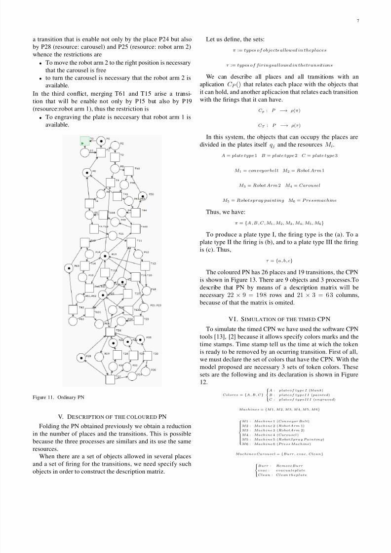
Figure 11. Ordinary PN
V. DESCRIPTION OF THE COLOURED PN
Folding the PN obtained previously we obtain a reduction
in the number of places and the transitions. This is possible
because the three processes are similars and its use the same
resources.
When there are a set of objects allowed in several places
and a set of firing for the transitions, we need specify such
objects in order to construct the description matriz.
Let us define, the sets:
π := types of objects allowed in theplaces
τ := types of firingsallowed in thetransitions
We can describe all places and all transitions with an
aplication C P () that relates each place with the objects that
it can hold, and another aplicacion that relates each transition
with the firings that it can have.
C p : P −→ ρ(π)
C T : P −→ ρ(τ )
In this system, the objects that can occupy the places are
divided in the plates itself q j and the resources M i.
A = plate type1 B = plate type2 C = plate type3
M 1 = conveyorbelt M 2 = Robot Arm1
M 3 = Robot Arm2 M 4 = Carousel
M 5 = Robotspray painting M 6 = P ressmachine
Thus, we have:
π = {A , B , C , M 1, M 2, M 3, M 4, M 5, M 6}
To produce a plate type I, the firing type is the (a). To a
plate type II the firing is (b), and to a plate type III the firing
is (c). Thus,
τ = {a ,b ,c}
The coloured PN has 26 places and 19 transitions, the CPN
is shown in Figure 13. There are 9 objects and 3 processes.To
describe that PN by means of a description matrix will benecessary 22 × 9 = 198 rows and 21 × 3 = 6 3 columns,
because of that the matrix is omited.
VI . SIMULATION OF THE TIMED CP N
To simulate the timed CPN we have used the software CPN
tools [13], [2] because it allows specify colors marks and the
time stamps. Time stamp tell us the time at wich the token
is ready to be removed by an ocurring transition. First of all,
we must declare the set of colors that have the CPN. With the
model proposed are necessary 3 sets of token colors. These
sets are the following and its declaration is shown in Figure
12.
Colores = {A , B , C}
A : plateof type I (blank)
B : plateof typeI I (painted)
C : plateof typeII I (engraved)
Machines = {M 1, M 2, M 3, M 4, M 5, M 6}
M 1 : Machine 1 (Conveyor Belt)
M 2 : Machine 2 (RobotArm 1)
M 3 : Machine 3 (RobotArm 2)
M 4 : Machine 4 (Carousel)
M 5 : Machine 5 (RobotSpray Painting)
M 6 : Machine 6 (Press Machine)
Machines Carousel = {Burr, evac, Clean}
Burr : RemoveBurr
evac : evacuateplate
Clean : Clean theplate

7/29/2019 Aticulo 2 Timed CPNversion Final
http://slidepdf.com/reader/full/aticulo-2-timed-cpnversion-final 8/9
8
Figure 12. Color set Declarations
Each of the places in the CPN must be associated with a
set of colors that are hold there, and the transitions must be
associated to a variables of a set or subset of colors.
The next step is to assign unit times to the transitions as
follows:
unittimes =
1 toup the robotArm 1
6 topaintthe plate
7 todry theplate
5 toengraving theplate
3 tobring tothe carousel
2 toturn thecarousel
5 toremovethe burr
3 tocleanthe plate
1 toevacuate theplate
To simulate the model of the system we start with 5
tokens of each color, so that the CPN can choose in a non
deterministic way the token color that enters to the system.
The CPN is shown in Figure 13 and the description of its
Places are in the Table XIV.
Figure 13. Timed Coloured Petri Net model
The time vector is an array that specify the time needed by
each of the concurrent procceses,
Transitionsdelays :
T i(+unittimei )
Process 1 : T 9 (1) + T 15 (3) + T 17(2) + T 18 (5) + T 19 (3) + T 20(1)
P rocess 2 : T 5 (6) + T 6 (7) + T 7 (1) + T 15(3) + T 17 (2) + T 18 (5) + T 19(3) + T 20 (1)
Table XIVPLACE DESCRIPTION COLOURED PETRI NET
PLACE DESCRIPTION COLOR SET
P1 Plate entering to the system A,B,C
P2 trasporting plate by conveyor belt A,B,C
P3 taking plate by M5 or by M2 A,B,C
P4 plate took by M5 or by M2 A,B,C
P5 painting plate B
P6 drying plate B
P7 up the painted plate with M2 B
P8 up the blank plate with M2 A,C
P9 Plate ready in top position A,B,C
P10 plate took by arm 2 or by arm 3 A,B,C
P11 bringing the plate to the carousel A,B
P12 engraving plate C
P13 bringing the plate to the carousel C
P14 plate ready to be download on the carousel A,B,C
P15 Rotating carousel A,B,C
P16 removing burr A,B,C
P17 burr removed A,B,C
P18 cleaning plate A,B,C
P19 plate cleaned A,B,C
P20 evacuating plate A,B,C
P21 plate evacuated A,B,C
P22 plate ready A,B,C
Process 3 : T 9 (1) + T 12(5) + T 13 (3) + T 17 (2) + T 18(5) + T 19(3) + T 20 (1)
Adding the times we have,
Transitionsdelays =
Procc 1 = [ 15 ]
Procc 2 = [ 28 ]
Procc 3 = [ 20 ]
and the time vector is:Time vector :
TimeP rocess1, T i meProcess2, T i meProcess3
Time vector = [15, 28, 20]
That time is an indication of the time required by produce a
type of plate, but the real process is non deterministic because
the plates arrive randomly and the system does not know what
color is the next to arrive. We can simulate a lot of times the
system in order to stablish an average of the number of plates
of each type produces in an interval of time.
A. Optimal Sequence
The Table XV, shown some times required to get a product
when the sequence of arrivals are the follows:
Performing several simulations it was found that the best
sequence is ACBA which uses 31 unit times. That sequence
can be extended as ACBACBACBA... to optimized the
production time.
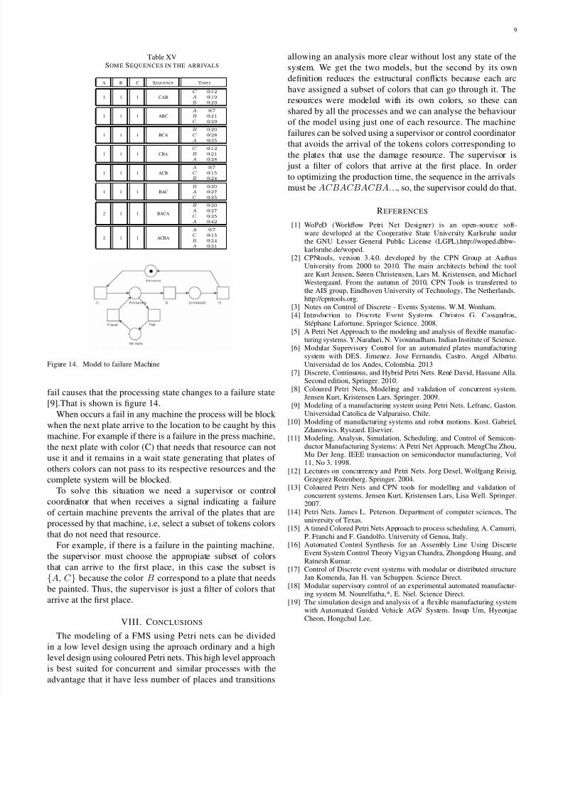
VII. MACHINE FAILURES
Let us assume that a failure can occurs only when the
machine (resource) is working or processing something, i.e.
in the places that represent an operation. That is, an event
7/29/2019 Aticulo 2 Timed CPNversion Final
http://slidepdf.com/reader/full/aticulo-2-timed-cpnversion-final 9/9
9
Table XVSOM E SEQUENCES IN THE ARRIVALS
A B C SEQUENCE TIMES
1 1 1 CAB
C @12A @19B @29
1 1 1 ABC
A @7B @21C @29
1 1 1 BCA
B @20C @28
A @35
1 1 1 CBA
C @12B @21A @28
1 1 1 ACB
A @7C @15B @24
1 1 1 BAC
B @20A @27C @35
2 1 1 BACA
B @20A @27C @35A @42
2 1 1 ACBA
A @7C @15B @24A @31
Figure 14. Model to failure Machine
fail causes that the processing state changes to a failure state
[9].That is shown is figure 14.
When occurs a fail in any machine the process will be block when the next plate arrive to the location to be caught by this
machine. For example if there is a failure in the press machine,
the next plate with color (C) that needs that resource can not
use it and it remains in a wait state generating that plates of
others colors can not pass to its respective resources and the
complete system will be blocked.
To solve this situation we need a supervisor or control
coordinator that when receives a signal indicating a failure
of certain machine prevents the arrival of the plates that are
processed by that machine, i.e, select a subset of tokens colors
that do not need that resource.
For example, if there is a failure in the painting machine,
the supervisor must choose the appropiate subset of colorsthat can arrive to the first place, in this case the subset is
{A, C } because the color B correspond to a plate that needs
be painted. Thus, the supervisor is just a filter of colors that
arrive at the first place.
VIII. CONCLUSIONS
The modeling of a FMS using Petri nets can be divided
in a low level design using the aproach ordinary and a high
level design using coloured Petri nets. This high level approach
is best suited for concurrent and similar processes with the
advantage that it have less number of places and transitions
allowing an analysis more clear without lost any state of the
system. We get the two models, but the second by its own
definition reduces the estructural conflicts because each arc
have assigned a subset of colors that can go through it. The
resources were modeled with its own colors, so these can
shared by all the processes and we can analyse the behaviour
of the model using just one of each resource. The machine
failures can be solved using a supervisor or control coordinator
that avoids the arrival of the tokens colors corresponding to
the plates that use the damage resource. The supervisor is
just a filter of colors that arrive at the first place. In order
to optimizing the production time, the sequence in the arrivals
must be ACBACBACBA..., so, the supervisor could do that.
REFERENCES
[1] WoPeD (Workflow Petri Net Designer) is an open-source soft-ware developed at the Cooperative State University Karlsruhe underthe GNU Lesser General Public License (LGPL).http://woped.dhbw-karlsruhe.de/woped.
[2] CPNtools, version 3.4.0. developed by the CPN Group at AarhusUniversity from 2000 to 2010. The main architects behind the toolare Kurt Jensen, Søren Christensen, Lars M. Kristensen, and MichaelWestergaard. From the autumn of 2010, CPN Tools is transferred tothe AIS group, Eindhoven University of Technology, The Netherlands.http://cpntools.org.
[3] Notes on Control of Discrete - Events Systems. W.M. Wonham.[4] Introduction to Discrete Event Systems. Christos G. Cassandras,
Stéphane Lafortune. Springer Science. 2008.[5] A Petri Net Approach to the modeling and analysis of flexible manufac-
turing systems. Y.Narahari, N. Viswanadham. Indian Institute of Science.[6] Modular Supervisory Control for an automated plates manufacturing
system with DES. Jimenez. Jose Fernando, Castro. Angel Alberto.Universidad de los Andes, Colombia. 2013
[7] Discrete, Continuous, and Hybrid Petri Nets. René David, Hassane Alla.Second edition, Springer. 2010.
[8] Coloured Petri Nets, Modeling and validation of concurrent system.Jensen Kurt, Kristensen Lars. Springer. 2009.
[9] Modeling of a manufacturing system using Petri Nets. Lefranc, Gaston.Universidad Catolica de Valparaiso, Chile.
[10] Modeling of manufacturing systems and robot motions. Kost. Gabriel,Zdanowics. Ryszard. Elsevier.
[11] Modeling, Analysis, Simulation, Scheduling, and Control of Semicon-ductor Manufacturing Systems: A Petri Net Approach. MengChu Zhou,Mu Der Jeng. IEEE transaction on semiconductor manufacturing, Vol11, No 3. 1998.
[12] Lectures on concurrency and Petri Nets. Jorg Desel, Wolfgang Reisig,Grzegorz Rozenberg. Springer. 2004.
[13] Coloured Petri Nets and CPN tools for modelling and validation of concurrent systems. Jensen Kurt, Kristensen Lars, Lisa Well. Springer.2007.
[14] Petri Nets. James L. Peterson. Department of computer sciences, Theuniversity of Texas.
[15] A timed Colored Petri Nets Approach to process scheduling. A. Camurri,P. Franchi and F. Gandolfo. University of Genoa, Italy.
[16] Automated Control Synthesis for an Assembly Line Using DiscreteEvent System Control Theory Vigyan Chandra, Zhongdong Huang, and
Ratnesh Kumar.[17] Control of Discrete event systems with modular or distributed structure
Jan Komenda, Jan H. van Schuppen. Science Direct.[18] Modular supervisory control of an experimental automated manufactur-
ing system M. Nourelfatha,*, E. Niel. Science Direct.[19] The simulation design and analysis of a flexible manufacturing system
with Automated Guided Vehicle AGV System. Insup Um, HyeonjaeCheon, Hongchul Lee.