The Return on Place: How to Boost Long Island's State of Place

MATERIALS & PROCESS DESIGN FOR HIGH TEMPERATURE CARBURIZINGIntegrating Processing & Performance
Goal: Integrate model-based robust control of the HTC with concurrent design of novel HTC steels for higher performance and processability
Challenge: Need mechanistic model to achieve robust control and performance Data to validate optimal processing
Benefits: 10X reduction in process cycle time, reduces scrap from quench distortion, enhanced performance through optimized steels, broader applications through deeper cases.
FY05 Activities: Robust application of new process model, demonstrate enhanced performance.
Participants:WPI (CHTE)NU (SRG)Midwest Thermal-VacGMQuesTek Innovations

Barrier-Pathway Approach
Barriers• Lack of industry
process control
• Lack of optimized steels
• Limited performance data
• Limited applications
Pathways• Mechanistic process
model for robust control
• Concurrent materials & process design (including final surface treatment)
• Industry test program
• Deeper cases
Critical Metrics• Acceptable part-to-part
variability (H, %C)
• Enhanced case hardness, residual stress, grain coarsening resistance, hardenability (reduced distortion)
• Fatigue Strength(single-tooth, RCF)
• New markets(camshafts, tool & die)
MATERIALS & PROCESS DESIGN FOR HIGH TEMPERATURE CARBURIZINGIntegrating Processing & Performance

MATERIALS & PROCESS DESIGN FOR HIGH TEMPERATURE CARBURIZINGIntegrating Processing & Performance
AIM Technology Acceleration
Higher Performance Energy Efficient Powertrain
Reduced Scrap (Eliminate Quench Distortion)
Process Energy Savings – 20 trillion BTU/Yr
CycleTime Reduction – 10X
Benefits (est.)

Gas Carburizing vs. Vacuum Carburizing
Limited by saturation of Austenite or formation of continuous filmsFaster (higher carbon potential/temp)More homogeneousVery predictable and reproducible
Surf
ace
carb
on c
onte
nt
0.85
1.0
0.2
%C
Time
Hold
Diffuse
Gas
0.85
1.0
0.2
%C
Time
Boost Intermediate diffuse
Final diffuse
Vacuum
Limited by soot formation
Midwest Thermal Vac

Features of Vacuum Carburizingand Capabilities of Software in Use
1) Diffusivity, D(C,T), varies with C content and time
2) Flux, J(t), varies with time
3) Carbide formation and dissolution
4) Multiple phase diffusion process (only after continuous film formation)
Simple 1-D:D(T)
J=constant
DICTRA 1-DD(C,T)
J(t)
Carbide formation and dissolution
Multiple phase diffusion
DEFORM 2D/3DD(C,T)
J (t)

Weight Gain and Surface Carbon Measurement for C61
Large enough surface area required for accurate weight gain measurement (for average or instant flux calculation)
Too long boost → carbide formation
Too long boost → retained austenite and plate martensite

Phases and Morphology after Long Boost for C69
Carbides on grain boundaries and left surfaceRetained austenite in casePlate shape martensite in case
5 um
20 um

Simulated Carbon and Measured Hardness Profile for C61
5 0 0
5 5 0
6 0 0
6 5 0
7 0 0
7 5 0
0 .0 0 0 0 .0 1 0 0 .0 2 0 0 .0 3 0 0 . 0 4 0 0 . 0 5 0 0 .0 6 0 0 .0 7 0 0 .0 8 0
Vick
ers
Har
dnes
s [H
V 50
0 g]
D e p t h f r o m S u r f a c e [ in c h ]
Simple 1D simulation
Real profile
Sur
face
C (w
t%)

DEFORM 3D Simulation for C61 Carburized at 950C
Boost + short diffuseDepth: ~ 139umSurface Hardness: ~ HRC 58
Boost onlyDepth: ~ 110umSurface Hardness: ~HRC 65
Corner effect:High C potential of the gasCan even be induced in diffuse cycles with low C potential

GUI of Versatile and Multi-constraint Software

GUI of Versatile and Multi-constraint Software
Challenge:When to start a final diffuse trialDICTRA workspace management (for rollback or different final diffuse trials)Exportation from workspaceFile management (plotting for different final diffuse trials)
Toughest challenge: implement all these flexibilities and constraints into one code

Case Study (1mm Depth)
Surface C
(max: 3 wt%)
Total C in region
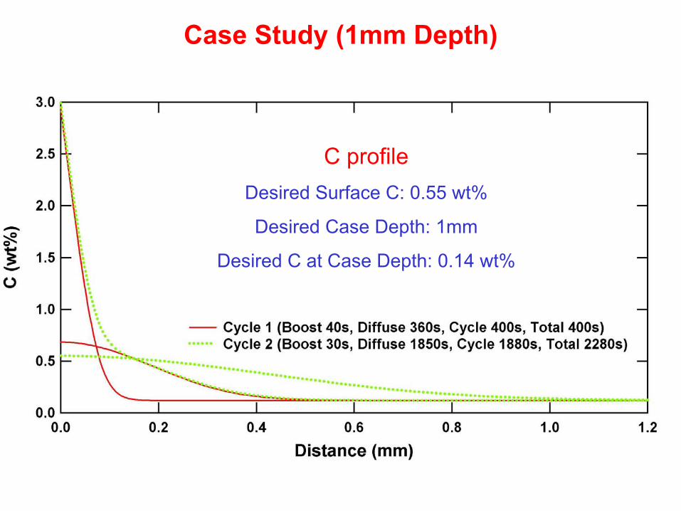
Case Study (1mm Depth)
C profileDesired Surface C: 0.55 wt%
Desired Case Depth: 1mm
Desired C at Case Depth: 0.14 wt%
14
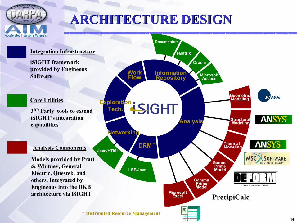
ARCHITECTURE DESIGNARCHITECTURE DESIGN
KBE
Work Flow
Analysis
Information Repository
LSF/Java
Geometric Modeling
Structural Modeling
Thermal Modeling
Gamma Prime Model
Microsoft Excel
Gamma Prime Model
PrecipiCalc
eMatrix
Oracle
Microsoft Access
Analysis Components
Models provided by Pratt & Whitney, General Electric, Questek, and others. Integrated by Engineous into the DKB architecture via iSIGHT
DRM *Java/HTML
Exploration Tech.
* Distributed Resource Management
Networking
3RD Party tools to extend iSIGHT’s integration capabilities
Integration Infrastructure
Core Utilities
iSIGHT framework provided by Engineous Software
Documentum
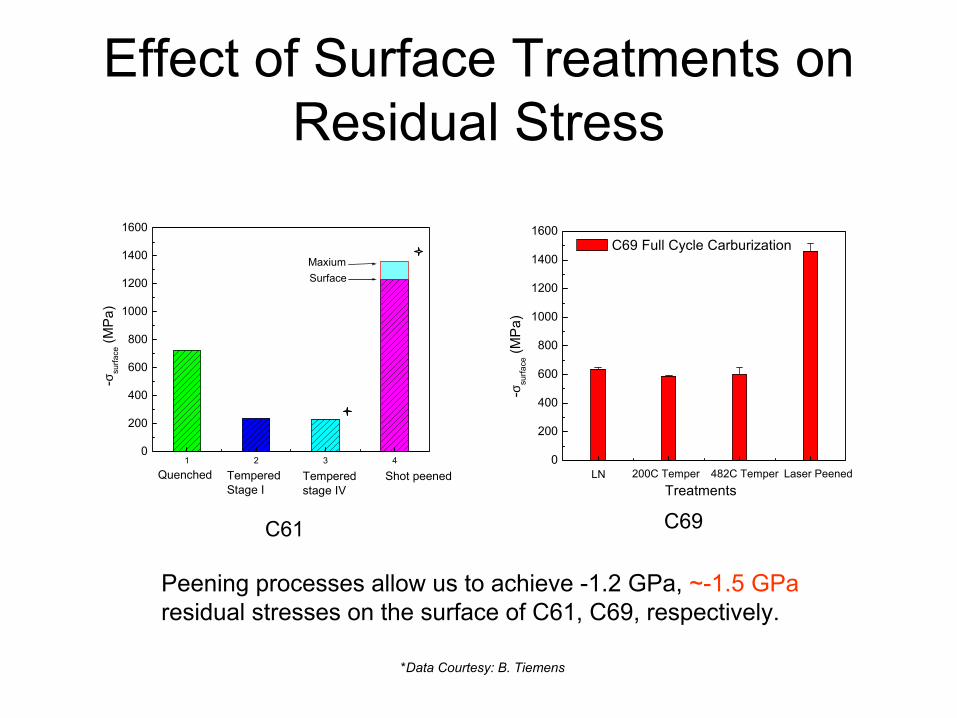
Effect of Surface Treatments on Residual Stress
0
200
400
600
800
1000
1200
1400
1600
Laser Peened482C Temper200C TemperLN
-σsu
rface
(MP
a)
Treatments
C69 Full Cycle Carburization
C61 C69
Peening processes allow us to achieve -1.2 GPa, ~-1.5 GParesidual stresses on the surface of C61, C69, respectively.
*Data Courtesy: B. Tiemens
1 2 3 40
200
400
600
800
1000
1200
1400
1600
SurfaceMaxium
Shot peenedTemperedstage IV
TemperedStage I
Quenched
-σsu
rface
(MP
a)

Effects of Surface Treatments
IN 718, Zhuang & Halford, International Journal of Fatigue, 2001 (23), S31
On Residual Stress
Res
idua
l Stre
ss (M
Pa)
Distance from surface (um)
Res
idua
l Stre
ss (M
Pa)
4340 steel sheet with both sides laser peened. The mid-thickness of the sheet is at 0.75mm
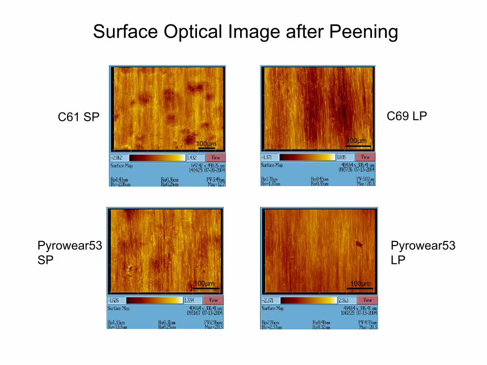
C69 LPC61 SP
Pyrowear53 SP
Pyrowear53 LP
Surface Optical Image after Peening
100µm
100µm
100µm
100µm

Surface Residual Stresses in Materials
0 100 200 300 400 500 600 700 800 9000
200
400
600
800
1000
1200
1400
1600
1800
2000
4340 Laser Peened
unpeened
720
C61 SPMaxSurface
C61
AISI 4140shot peened
C69
M50 M50NiLAISI 52100
AISI 4340
-σsu
rface
(MP
a)
Surface Hardness (VHN)
Pyrowear53 SP
Pyrowear53 LP
C69 LP 1.5GPa
1.0GPa

APS Experiment
E ~ 80 keV
Conical Slit
3D Probe of Strain/Stress
Conical Slit 2D Detector

C69
Ultimate Bending Strength
Displacement (mm)
0.00 0.25 0.50 0.75 1.00 1.25 1.50 1.75 2.00
Appr
oxim
ate
Ben
ding
Str
ess
(MPa
)
0
1000
2000
3000
4000
5000
Appl
ied
Tens
ile L
oad
(N)
0
2e+4
4e+4
6e+4
8e+4
1e+5
Premium Steel
C69
Single Tooth Bending Fatigue Performance
log (Cycles)
3 4 5 6 7
Max
imum
App
lied
Tens
ile S
tres
s (M
Pa)
1000
1200
1400
1600
1800
2000
2200
Premium SteelC69
Baseline Steel

C61
Ultimate Bending Strength
Displacement (mm)
0.00 0.25 0.50 0.75 1.00 1.25 1.50 1.75 2.00
Appl
ied
Tens
ile L
oad
(N)
0
2e+4
4e+4
6e+4
8e+4
1e+5
Appr
oxim
ate
Ben
ding
Str
ess
(MPa
)
0
1000
2000
3000
4000
5000C61-'04
C61-'03
Premium Steel
Single Tooth Bending Fatigue Performance
log (Cycles)
3 4 5 6 7
Max
imum
App
lied
Tens
ile S
tres
s (M
Pa)
1000
1200
1400
1600
1800
2000
2200C61 - '04
Premium Steel
C61 - '03
Baseline Steel

Role of LoadSurface Residual Stress of Fatigue Tracks
Fatigue TrackNon-fatigue trackMaterial
823±4Relaxation: -42%
1085±6Relaxation: -23%
1410±31418±33Pyrowear53, LP
756±3Relaxation: -20%
?1569±7946±21119±5Pyrowear53, SP
Hoop (MPa)Axial (MPa)Hoop (MPa)
Axial (MPa)
Residual stress relaxation of laser peened material is greater than that of shot peened material.

ID Number
Task / Milestone Description Planned Completion
Actual Completion
Comments
1a ThermoCalc Modeling 7/31/05 90% 1b Process Experiments 7/31/05 80% 1c Industrial Experiments 7/31/05 35% 1d Hardenability 10/31/03 10% 2a Redesign Alloys 10/31/04 60% 2b Grain Stability 10/31/04 60% 3a RCF and Wear 7/31/05 50% 3b Residual Stress 7/31/05 35% 3c Redesign for Performance 7/31/05 30% 3d Forming Dies 7/31/05 20% 3e Forging/Casting Dies 7/31/05 0%

Microstructural Design Example: C69• Gears
– 0.015” to 0.050” case– 0.040” typical
• Camshafts– 0.100” typical
50
52
54
56
58
60
62
64
66
68
0 0.02 0.04 0.06 0.08 0.1 0.12Case Depth (inches)
Roc
kwel
l Har
dnes
s
50
52
54
56
58
60
62
64
66
68
0 0.02 0.04 0.06 0.08 0.1 0.12
Case Depth (inches)
Roc
kwel
l Har
dnes
s

Current Sales Ferrium® C61
CamshaftsRing and Pinion

Commercialization History of Carburized Alloys
• Product Sales– Ring and Pinion– Camshafts
• Application Trials– Gears
• Racing• Aerospace• Helicopter• Marine
– Dog Rings (racing)– Input Shafts (racing)– Roll Forms– Cutlery– Skate Blades
• Markets Surveyed– Ball Screws
– Tool and Die
– Golf Clubs

Materials to be studied at WPI
• 8160 gears -- GM• 5120 gears -- GM• 8620 shafts -- Deere• SAE 4118/4122 -- CAT• SAE 9310 -- CAT• Fe-Mo-Ni (P/M)-- Hoeganaes Corp.• Fe-Cr-Mn-Mo (P/M) -- Hoeganaes Corp.
Carburization trial will be conducted at Surface Combustion,OH, using their low pressure carburizing facilities.
FY05 (Y4) Plans
•AIM / iSIGHT robust process design
•Residual stress optimization of C69
•Performance testing of PM-C69Ti
•Prototype characterization of new LC alloys
•Quantify CCT
•Expand deep case applications (cams; tool & die)
•CHTE dissemination of process control (vendors & steels)