Asynchronous Motors
31
Asynchronous motors Asynchronous motors are used in a wide variety of applications. Here are some examples of driven machines: - centrifugal pumps, - fans and blowers, - compressors, - crushers, - conveyors, - lifts and cranes, - … The consequence of a motor failure due to an incorrect protection or inability of control circuit to operate can include the following: For persons: - Asphyxiation due to the blockage of motor ventilation - Electrocution due to insulation failure in the motor - Accident due to non stopping of the motor following a control circuit failure For the driven machine and the process:, - Shaft couplings, axles, driving belts, … damaged due to a stalled rotor - Lost production - Delayed manufacturing For the motor itself: - Motor windings burnt out due to stalled rotor - Cost of repair - Cost of replacement Therefore, safety of persons and goods, as well as reliability and availability levels, are highly dependent on the selection of protective equipment. In economic terms, the overall cost of failure must be considered. This cost is increasing with the size of the motor and with the difficulties of access and replacement. Loss of production is a further and evidently important factor. Specific features of motor performance influence the power
Transcript of Asynchronous Motors

Asynchronous motorsAsynchronous motors are used in a wide variety of applications. Here are some examples of driven machines: - centrifugal pumps,- fans and blowers,- compressors,- crushers,- conveyors,- lifts and cranes,- …The consequence of a motor failure due to an incorrect protection or inability of control circuit to operate can include the following:
For persons:
- Asphyxiation due to the blockage of motor ventilation - Electrocution due to insulation failure in the motor - Accident due to non stopping of the motor following a control circuit failure
For the driven machine and the process:,
- Shaft couplings, axles, driving belts, … damaged due to a stalled rotor - Lost production - Delayed manufacturing
For the motor itself:
- Motor windings burnt out due to stalled rotor - Cost of repair - Cost of replacementTherefore, safety of persons and goods, as well as reliability and availability levels, are highly dependent on the selection of protective equipment.In economic terms, the overall cost of failure must be considered. This cost is increasing with the size of the motor and with the difficulties of access and replacement. Loss of production is a further and evidently important factor.Specific features of motor performance influence the power supply circuits required for satisfactory operationA motor power-supply circuit presents certain constraints not normally encountered in other (common) distribution circuits. These are owing to the particular characteristics of motors directly connected to the line, such as:
High start-up current (see Fig. N62) which is mostly reactive, and can therefore be the cause of important voltage drop
Number and frequency of start-up operations are generally high The high start-up current means that motor overload protective devices must have
operating characteristics which avoid tripping during the starting period.

Fig. N62: Direct on-line starting current characteristics of an induction motor
Contents
1 Motor control systems 2 Motor protection functions 3 Motor monitoring 4 Motor starter configurations 5 Protection coordination 6 Basic protection scheme: circuit-breaker + contactor + thermal relay 7 Control and protection switching gear (CPS) 8 Intelligent Power and Motor Control Centre (iPMCC) 9 Communication
Motor control systems
Different kinds of motor control solution are compared in the following tables.

Is / In Ts / Tn Speed control Torque control
Direct on line 5-10 5-10 No No
Star – Delta 2-3 1-2 No No
Auto-tranformer 2-3 1-2 No No
Soft starter 3-5 1.5-2.5 No Yes
Variable speed drive 1.5 1.5-2 Yes Yes
pros cons
Direct on line Reduced cost Hight starting torque when necessary
Hight in-rush current, High torque so high contrainsts on motor, mechanics, ... not necessarily needed for the application starting
Star – Delta Reduced in-rush current Reduced starting torque, switching voltage & currents
Auto-tranformer
Reduced in-rush current Hight weight
Soft starter
Reduced in-rush current controlled start and stop
Interesting solution in medium voltage as good value for money
Reduced starting torque
Variable speed drive
Controlled speed Energy saving at reduced speed
Sometimes the main "modern" solution according to the driven process characteristics
Higher cost
Fig. N63a: Comparison of different motor control solution
Motor protection functions
These are the arrangements implemented in order to avoid operation of motors in abnormal conditions which could result in negative events such as: overheating, premature ageing, destruction of electrical windings, damage to coupling or gear box, …

Three levels of protection scheme are commonly proposed: "Conventional", "Advanced", "High Performance", which can be adopted depending on the sophistication and power of the driven machine.
- "Conventional" protection functions apply for every type of motor or application, - "Advanced" protection functions apply to more sophisticated machines requesting special
attention, - "High performance" protection functions are justified for high power motors, high demanding applications, or motors in critical process.
Protection Conventional Advanced High Performance
Short-circuit
Thermal overload
Phase current imbalance
Phase current loss
Over-current
Ground fault
Long start
Jam
Under-current
Phase current reversal
Motor temperature (by sensors)
Rapid cycle lock-out
Load shedding
Phase voltage imbalance
Phase voltage loss
Phase voltage reversal
Under-voltage
Over-voltage
Under-power
Over-power
Under power factor
Over power factor
Fig. N64: Classification des fonctions de protection
Here is a list of motor protection functions and the result of activation.

Short-circuit: disconnection in case of a short-circuit at the motor terminals or inside the motor windings.
Thermal overload: disconnection of motor in case of sustained operation with a torque exceeding the nominal value. Overload is detected by measurement of excessive stator current or by using PTC probes.
Phase current imbalance: disconnection of the motor in case of high current imbalance, responsible for increased power losses and overheating.
Phase current loss: disconnection of the motor if one phase current is zero, as this is revealing of cable or connection breaking.
Over-current: alarm or disconnection of the motor in case of high phase current, revealing a shaft over-torque.
Ground fault: disconnection in case of a fault between a motor terminal and ground. Even if the fault current is limited, a fast action could avoid a complete destruction of the motor.
Long start (stall): disconnection in case of a starting time longer than normal (due to mechanical problem or voltage sag) in order to avoid overheating of the motor.
Jam: disconnection in order to avoid overheating and mechanical stress if motor is blocked while running because of congestion.
Undercurrent: alarm or disconnection of the motor in case a low current value is detected, revealing a no-load condition (e.g.: pump drain, cavitation, broken shaft, …)
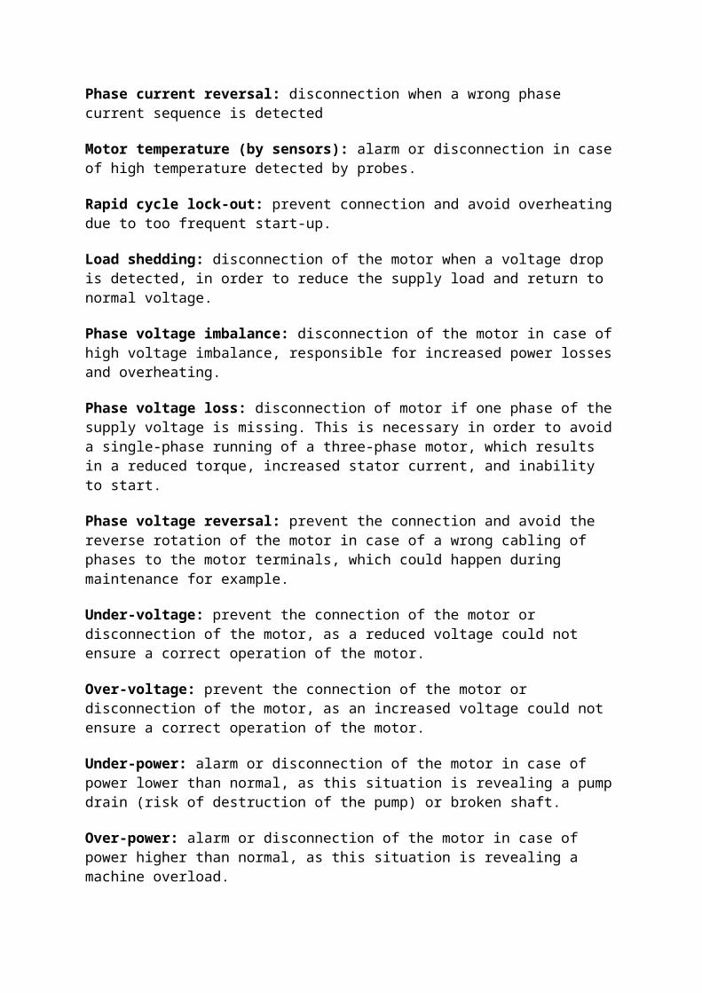
Phase current reversal: disconnection when a wrong phase current sequence is detected
Motor temperature (by sensors): alarm or disconnection in case of high temperature detected by probes.
Rapid cycle lock-out: prevent connection and avoid overheating due to too frequent start-up.
Load shedding: disconnection of the motor when a voltage drop is detected, in order to reduce the supply load and return to normal voltage.
Phase voltage imbalance: disconnection of the motor in case of high voltage imbalance, responsible for increased power losses and overheating.
Phase voltage loss: disconnection of motor if one phase of the supply voltage is missing. This is necessary in order to avoid a single-phase running of a three-phase motor, which results in a reduced torque, increased stator current, and inability to start.
Phase voltage reversal: prevent the connection and avoid the reverse rotation of the motor in case of a wrong cabling of phases to the motor terminals, which could happen during maintenance for example.

Under-voltage: prevent the connection of the motor or disconnection of the motor, as a reduced voltage could not ensure a correct operation of the motor.
Over-voltage: prevent the connection of the motor or disconnection of the motor, as an increased voltage could not ensure a correct operation of the motor.
Under-power: alarm or disconnection of the motor in case of power lower than normal, as this situation is revealing a pump drain (risk of destruction of the pump) or broken shaft.
Over-power: alarm or disconnection of the motor in case of power higher than normal, as this situation is revealing a machine overload.
Under power factor: can be used for detection of low power with motors having a high no-load current.
Over power factor: can be used for detection of end of the starting phase.
The consequence of abnormal overheating is a reduced isolation capacity of the materials, thus leading to a significant shortening of the motor lifetime. This is illustrated on Figure N65, and justifies the importance of overload or over-temperature protection.
Fig. N65: Reduced motor lifetime as a consequence of overheating
Overload relays (thermal or electronic) protect motors against overloads, but they must allow the temporary overload caused by starting, and must not trip unless the starting time is abnormally long.Depending on the application, the motor starting time can vary from a few seconds (for no-load starting, low resistive torque, etc.) to several tens of seconds (for a high resistive torque, high inertia of the driven load, etc.). It is therefore necessary to fit relays appropriate to the starting time.To meet this requirement, IEC Standard 60947-4-1 defines several classes of overload relays, each characterized by its tripping curve (see Fig. N65a ).The relay rating is to be chosen according to the nominal motor current and the calculated starting time.Trip class 10 is adapted to normal duty motors.Trip class 20 is recommended for heavy duty motorsTrip class 30 is necessary for very long motor starting.
Fig. N65a: Tripping curves of overload relays

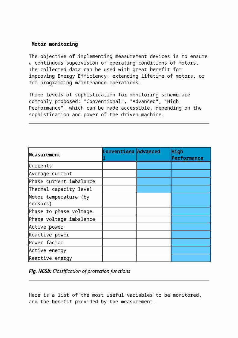
Motor monitoring
The objective of implementing measurement devices is to ensure a continuous supervision of operating conditions of motors. The collected data can be used with great benefit for improving Energy Efficiency, extending lifetime of motors, or for programming maintenance operations.
Three levels of sophistication for monitoring scheme are commonly proposed: "Conventional", "Advanced", "High Performance", which can be made accessible, depending on the sophistication and power of the driven machine.
Measurement Conventional Advanced High Performance
Currents
Average current
Phase current imbalance
Thermal capacity level
Motor temperature (by sensors)
Phase to phase voltage
Phase voltage imbalance
Active power
Reactive power
Power factor
Active energy
Reactive energy
Fig. N65b: Classification of protection functions
Here is a list of the most useful variables to be monitored, and the benefit provided by the measurement.
Currents: they are directly responsible for the conductors heating and thus for a possible time life reduction. These are the most important variables to monitor. The current measurement also gives a direct indication on the motor load and stress applied to the driven machine.
Average current: to know the average load of the motor, whether the motor is well adapted to the driven machine or not.
Phase current imbalance: as imbalance is responsible for additional losses in the motor, phase current imbalance is an important variable to monitor.

Thermal capacity level: knowledge of the remaining overload capability and safety margin.
Motor temperature (by sensors): knowledge of the real thermal operating conditions, taking account of motor load, ambient temperature, ventilation efficiency.
Phase to phase voltage: too high or too low phase voltages are responsible of increased motor current for a given load. Voltage monitoring is thus indicating whether the motor is operating in normal conditions or not.
Phase voltage imbalance: as imbalance is responsible for additional losses in the motor, phase voltage imbalance is an important variable to monitor.
Active power: indication of the load level applied to the motor.
Reactive power: indication of the reactive power that could be necessary to compensate by implementation of capacitors.
Power factor: indication of load level of the motor. If Power Factor is > 1: submit your candidacy for the Physics Nobel Prize.
Active energy: possibility to relate the consumed energy to the operating time or the quantity of goods produced by driven machine.
Reactive energy: possibility to determine the necessity of implementation of capacitors in order to avoid payment of penalties to the Utility.
Fig. N65c: Example of motor management system with "High performance" protection and monitoring functions (TeSys T Schneider Electric)
Motor starter configurations
Different configurations of switchgear and control-gear are commonly proposed. Some examples are shown on Figure N66.
Fig. N66: The various functions and their combinations forming a motor starter
The different applicable standards are listed on Figure N67.
Standard Title
IEC 60947-1 Low-voltage switchgear and controlgear – General rules
IEC 60947-4-1 Contactors and motor-starters –Electromechanical contactors and motor-starters
IEC 60947-4-2 Contactors and motor-starters – AC semiconductor motor controllers and starters
IEC 60947-6-2 Multiple function equipment – Control and protective switching devices (or equipment) (CPS)
IEC 61800 Adjustable speed electrical power drive systems
Fig. N67: Applicable standards

Different utilization categories have been defined for contactors in IEC 60947-4-1. The selection relative to asynchronous motor control is given in Figure N68.
Category Typical applications
AC-1 Non-inductive or slightly inductive loads, resistance furnaces
AC-2 Slip-ring motors: starting, switching off
AC-3 Squirrel-cage motors: starting, switching off motors during running
AC-4 Squirrel-cage motors: starting, plugging(1), inching(2)
1) By plugging is understood stopping or reversing the motor rapidly by reversing motor primary connections while the motor is running.2) By inching (jogging) is understood energizing a motor once or repeatedly for short periods to obtain small movements of the driven mechanism
Fig. N68: Different categories of AC contactors used for asynchronous motor control
Protection coordination
Type 1 and Type 2 coordination are defined in IEC 60947-4-1.Total coordination is offered by some manufacturers.
Coordination Consequence of a short circuit Application field
Type 1 The contactor or starter shall cause no danger to persons and installation and may not be suitable for further service without repair and replacement of parts.
General purpose application. Basic machines.
Type 2 The contactor or starter shall cause no danger to persons or installation and shall be suitable for further use. The risk of contact welding is recognized, in which case the manufacturer shall indicate the measures to be taken as regards the maintenance of the equipment.
Process with availability constraints, e.g.: continuous process, critical industrial machines.
Continuity of service(total coordination)
No damage or maladjustment is permissible.Must be able to restart immediately after fault is corrected No special precaution is required.
Fig. N69: Level of acceptable destruction according to the condition types
Basic protection scheme: circuit-breaker + contactor + thermal relay

Among the many possible methods of protecting a motor, the association of a circuit breaker + contactor + thermal relay (1) provides many advantages
The combination of these devices facilitates installation work, as well as operation and maintenance, by:
The reduction of the maintenance work load: the circuit-breaker avoids the need to replace blown fuses and the necessity of maintaining a stock (of different sizes and types)
Better continuity performance: the installation can be re-energized immediately following the elimination of a fault and after checking of the starter
Additional complementary devices sometimes required on a motor circuit are easily accommodated
Tripping of all three phases is assured (thereby avoiding the possibility of “single phasing”)
Full load current switching possibility (by circuit-breaker) in the event of contactor failure, e.g. contact welding
Interlocking Diverse remote indications Better protection for the starter in case of over-current and in particular for impedant
short-circuit (2) corresponding to currents up to about 30 times In of motor (see Fig. N67)
Possibility of adding RCD:
- Prevention of risk of fire (sensitivity 500 mA) - Protection against destruction of the motor (short-circuit of laminations) by the early detection of earth fault currents (sensitivity 300 mA to 30 A).
(1) The combination of a contactor with a thermal relay is commonly referred to as a «discontactor».
(2) In the majority of cases, short circuit faults occur at the motor, so that the current is limited by the cable and the wiring of starter and are called impedant short-circuits.

Fig. N70: Tripping characteristics of a circuit-breaker + contactor + thermal relay
The combination of a circuit-breaker + contactor + thermal relay for the control and protection of motor circuits is eminently appropriate when:
The maintenance service for an installation is reduced, which is generally the case in tertiary and small and medium sized industrial sites
The job specification calls for complementary functions There is an operational requirement for a load breaking facility in the event of need of
maintenance.
Control and protection switching gear (CPS)
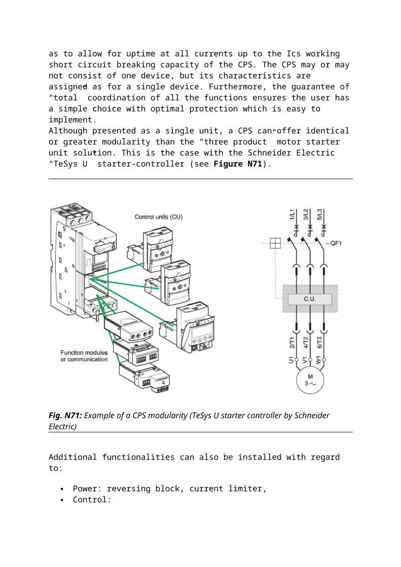
CPS or “starter-controllers” are designed to fulfil control and protection functions simultaneously (overload and short-circuit). In addition, they are designed to carry out control operations in the event of short-circuit.They can also assure additional functions such as insulation, thereby totally fulfilling the function of “motor starter unit”. They comply with standard IEC 60947-6-2, which notably defines the assigned values and utilisation categories of a CPS, as do standards IEC 60947-1 and 60947-4-1.The functions performed by a CPS are combined and coordinated in such a way as to allow for uptime at all currents up to the Ics working short circuit breaking capacity of the CPS. The CPS may or may not consist of one device, but its characteristics are assigned as for a single device. Furthermore, the guarantee of “total” coordination of all the functions ensures the user has a simple choice with optimal protection which is easy to implement.Although presented as a single unit, a CPS can offer identical or greater modularity than the “three product” motor starter unit solution. This is the case with the Schneider Electric “TeSys U” starter-controller (see Figure N71).

Fig. N71: Example of a CPS modularity (TeSys U starter controller by Schneider Electric)
Additional functionalities can also be installed with regard to:
Power: reversing block, current limiter, Control:
- Function modules, alarms, motor load monitoring, automatic resetting, etc, - Communication options such as Ethernet, Modbus, Profibus, DeviceNet, CAN-Open, ASI, etc, - Auxiliary contact modules.

Available functions Standard Upgradeable Multifonction
Starter status (ready, running, with default)
Start and Stop controls
Thermal alarm
Remote resetting by bus
Indication of motor load
Defaults differentiation
Alarms (overcurrents…)
Parameter setting and protection function reference
“Log file” function
“Monitoring” function
Information conveyed by bus (Modbus or any other communication protocols) and functions performed
Fig. N72: TeSys U Communication functions
Intelligent Power and Motor Control Centre (iPMCC)
iPMCC is a system integrating intelligent Motor Protection Relays (IMPR) in a highly dependable Power and Motor Control Centre switchboard. Connectivity to the supervision and control system is provided through an industrial communication network.This solution is particularly used in large industrial sites and infrastructures, with continuous or hybrid process, and whenever continuity of service is a priority.
intelligent Motor Protection Relay
IMPR is the key component of an iPMCC offer. It is a microprocessor controlled device. Motor monitoring and protection is performed based on measurements from sensors, such as current transformers, voltage transformers (embedded or external), thermal sensor, earth leakage detector,… From these measurements and the settings, it determines fault conditions or potential risks for motors and operators.According to the motor protection model, an IMPR has the capability to detect many kinds of faults. It is a great improvement compared to thermal relay protection. Moreover, many complementary functions can be implemented by an IMPR: monitoring, alarming, fault recording, statistics, communication, etc…

1: TeSys T motor protection relay with communication capability 2: extension module with voltage measurement 3: phase current sensors 4: earth leakage detector 5, 6, 7: Human Machine Interface
Fig. N73: Example of motor control and protection architecture
Motor Control CentreA Motor Control Centre (MCC) is an electrical switchboard which groups all motor starters of a process, in order to build a centralised installation. Motor starters management centralisation is requested in many industries and infrastructures, in order to facilitate operation and maintenance. Withdrawable MCC functional units (FU) are used in critical applications, as they are more convenient to manage in case of fault. The faulty motor starter can be replaced quickly, without shutting down the whole switchboard.Fixed or disconnectable FUs can be used in less critical applications.
MCC installation system must be a "Type Tested Assembly" (TTA) to guarantee availability, safety and reliability of the application. In an iPMCC configuration, type test, especially temperature rising test, is essential because the IMPR (electronic device) is more sensitive to

heat. Furthermore, MCC should provide a dependable and reliable communication bus connection.
A MCC is different from a universal cabinet in the way that a universal cabinet can only be used to accommodate a group of few motor starters. It has lower electrical characteristics requirements, and it does not provide the separation between motor starters in different functional units. Therefore, in an universal cabinet complete shutdown will be necessary before maintenance operations or any reconfiguration of the starters.
Fig. N74: Example of iPMCC: Okken switchboard and drawers by Schneider Electric
iPMCC offers great advantages at all the project stages: design, execution as well as operations.
Improved project efficiency
- Reduction of engineering as starters are more standardised over a wider power range, - Reduction of on-site wiring time thanks to field buses, - Reduction of set-up time thanks to download of parameters.
Reduced commissioning time
- Better understanding of the process reactions thanks to detailed diagnostics and statistics, - Faster error fixing and bug tracking, - Easier fixing of process start-up problems.
Improved Continuity of Service
- Better protection of motors and loads by using more accurate sensors and more accurate motor protection models, - Reduced untimely downtime with alarms giving time to fix the problem before tripping occurs.
Reduced operating and maintenance cost
- Less downtime, - Faster problem fixing, - Less spare parts stock, - Preventive maintenance strategy
Reduced evolution cost and time
- Simplified engineering, - No wiring required, - Simplified set-up, - Easier Process tuning and commissioning.A complete iPMCC offer concentrates the knowledge and experience of electrical distribution, motor protection and control, automation and installation. This is why only a few leading companies in electrical distribution and automation can propose this offer.
Communication
An iPMCC configuration is made of lots of motor starters. In order to supervise the system, it is necessary to send information such as motor status, current values, alarms, etc… The traditional wire-to-wire connection is not an efficient and cost-effective way when there is a lot of data to be transmitted. Today, transmission via a communication network is the preferred way.The communications need the support of a common language, which is the communication protocol. The following chart shows the protocols commonly used at different levels of an industrial communications networks. At the moment, the most popular device bus protocols are Modbus SL, Profibus-DP and DeviceNet, while Ethernet TCP/IP is growing very fast.

Fig. N75: Different communication protocols
ModbusModbus is a message handling structure introduced by Modicon in 1979. Modbus is an application level protocol based on the OSI model. It is independent of the physical layer.
Fig. N76: Modbus architecture
Modbus SL (Serial Line)Modbus can be implemented on RS232, RS442 or RS485 links as well as other media like

Ethernet. Modbus RS485 has been the most common protocol in the world. It supports communications speed up to 115kbps, but most devices support only communication up to 19.2 kbps.
Modbus RS485 is a low cost communication implementation, and it has the largest installation base and supplier network. The weak point of Modbus is the transmission speed (since it is limited by serial line speeds) and maximum number of devices. Modbus may face some problems in the application of very large industrial site, but it is still an economical and reasonable choice to the majority of motor protection systems.
Modbus is based on a Master/Slave concept. One device is the master and sends request to read or write data to each slave in turn. Slave answers to requests from the master. Even though you can have many devices connected to one serial line only one device can talk at a time.
Fig. N77: Modbus SL architecture
Modbus/TCPModbus/TCP is an excellent choice for large sites applications. Modbus/TCP uses the standard 10Mbps Ethernet media in physical layers to carry the Modbus message handling structure. It offers very fast speed and big number of devices in one network; it is easier to integrate MCC into the Local Area Network (LAN) of a company, so it is the choice of more and more customers.
Unlike Modbus SL, Modbus/TCP works on a Client/Server concept:
A client initiates the requests and a server answers, Any device can be a client or a server, Many devices are both client and server at the same time, A network can consist of many clients.

Fig. N77a: Modbus SL architecture
Many clients can send requests at the same time and many servers can answer at the same time:
A client can talk to multiple servers at the same time, A server can answer multiple clients at the same time, Ethernet switches take care of packet delivery to all a devices at the same time.
Fig. N78: Typical communication architecture

Differences between Modbus/TCP and Modbus SL:
Devices can be a client and a server at the same time. Everyone can talk at the same time: multiple devices can initiate communications, not
just one. Increases system response time by parallel communications. Multiple requests can be sent from one device to another without waiting for the first
request to be answered. A new piece of data is added to the Modbus frame called the Modbus Transaction identifier to allow a response to be matched to a specific request.
The Transmission speed is much increased:10Mb, 100Mb, 1Gb etc. The transmission media is much more flexible and costs are lower: fibre, radio etc. The number of nodes on a single network is almost unlimited: maximum
recommended is around 300, but routers can be used to join several networks.
Modbus I/O ScanningModbus I/O Scanning is a feature in Schneider Electric Programmable Logic Controllers (PLC) which allows simple Modbus transactions with a simple setup screen. It is only requested to set the address, poll time and data to read and/or write.
Fig. N79: Modbus SL architecture

ProfibusProfibus is a protocol introduced by a fieldbus working group in 1987. This group consists of 13 industrial organizations and 5 research institutes. Now, Profibus is managed by a user group which includes manufacturers, users and researchers.Profibus-DP is the version of Profibus used at device level. It has been a successful protocol in the last decades, especially in Europe. Profibus-DP is a protocol with high transmission speed. It supports the communication up to 12 Mbps, but actually 1.5 Mbps is the most practical maximum value in applications because it may need special transmission media and it should be implemented in a short distance to achieve the transmission speed up to 12 Mbps.
DeviceNetDeviceNet is a protocol based on CAN, which is a protocol widely used in the automotive industry. ODVA (Open DeviceNet Vendor Association) takes now the responsibility to promote and provide technical support to DeviceNet specification.ODVA is an international association comprised of members from the world's leading automation companies. Collectively, ODVA and its members support network technologies using the Common Industrial Protocol (CIP™). These currently include DeviceNetTM, EtherNet/IPTM, CompoNetTM and the major extensions to CIP — CIP SafetyTM, CIP SyncTM, and CIP MotionTM. ODVA manages the development of these open technologies and assists manufacturers and users of CIP Networks through tools, training and marketing activities.DeviceNet provides communication with 3 possible speeds: 125, 250 or 500 kbps, which depends on the bus length and cable as well as product consumption. The maximum number of devices is 64, including master devices. The bus length is limited to 100m at 500 kbps.
Synthetic viewThe following table shows a short (non-exhaustive) comparison of these protocols:
Modbus SL RS485
Profibus-DP DeviceNet Modbus/TCP
Speed up to 115 kbps 9.6 kbps to 1 Mbps 125, 250 or 500 kbps
10 / 100Mbps / 1Gbps
Max. distance without repeaters
1300 m 100m at 12Mbps1.2km at 10kbps
100m at 500kbps500m at 125kbps
Twisted pair: 100mOptical fibre: 2000m
Max. number of devices
32: 1 master and 31 slaves
126: mono or multi-masters, 122 slaves max with 3 repeaters
64: 1 master and 63 slaves
64 with I/O scanning; no limit with others
Max. distance with repeaters
Depends on the type of repeater
400 to 4800m according to speed Depends on the type
of repeater
10km optical fibre
Fig. N80: Comparison of communication protocols