Asynchronous and Doubly-Fed Generators, Model 8052
35
Electric Power / Controls Courseware Sample 85822-F0 A
Transcript of Asynchronous and Doubly-Fed Generators, Model 8052
Electric Power / Controls
Courseware Sample
85822-F0
A


ELECTRIC POWER / CONTROLS
COURSEWARE SAMPLE
bythe Staff
ofLab-Volt Ltd.
Copyright © 2009 Lab-Volt Ltd.
All rights reserved. No part of this publication may be reproduced,in any form or by any means, without the prior written permissionof Lab-Volt Ltd.
Printed in CanadaOctober 2009

III
Table of ContentsIntroduction . . . . . . . . . . . . . . . . . . . . . . . . . . . . . . . . . . . . . . . . . . . . . . . . . . . V
Courseware Outline
Asynchronous and Doubly-Fed Generators . . . . . . . . . . . . . . . . . . . . . . . . VII
Sample Exercise Extracted from Asynchronous and Doubly-Fed Generators
Exercise 3-9 The Boost Chopper . . . . . . . . . . . . . . . . . . . . . . . . . . . . . . . 3
Instructor Guide Sample Exercise Extracted from Asynchronous andDoubly-Fed Generators
Exercise 3-11 The Four-Quadrant Chopper . . . . . . . . . . . . . . . . . . . . . . . 17
Bibliography

IV

V
Introduction
The Lab-Volt Asynchronous and Doubly-Fed Generators system, model 8052-1,introduces the principles of electrical power generation and control in the field of windturbines.
Known as the standard for technical training systems in use across virtually everyindustry and around the globe, Lab-Volt is now using its expertise to facilitate thedevelopment, production, installation, and maintenance of the widest variety ofAlternative and Renewable Energy Power Training Systems.
While most power generation requires the creation, management, and conversionof heat energy into motion—with most variations simply involving the way heat isproduced—alternative and renewable sources are far more varied.
Many take advantage of the motion already found in nature; others harness nature’sown renewable forms of heat and energy. Capturing and converting that motion orenergy often requires very non-traditional methods.
Accustomed to breaking down processes and procedures into elemental blocks,Lab-Volt’s new training systems take the esoteric and theoretical out of thelaboratory and translate it into apparatus that introduce practical, understandableteaching methods.
Regardless of the operational scale of the alternative energy sources , Lab-Volt hasdistilled the essential elements of the process down to safe, hands-on classroomapplications, developing each training product and process to yield realistic,repeatable, and logical results.

VI
ASYNCHRONOUS AND DOUBLY-FED GENERATORS
Courseware Outline
VII
Unit 1 Fundamentals for Rotating Machines
Introduction to rotating machines. Work, speed, torque, and power.Operation of the Prime Mover / Dynamometer module.
Ex. 1-1 Prime Mover Operation
Familiarization with the Prime Mover / Dynamometer moduleoperating in the Prime Mover mode. Prime mover speed versusvoltage. Friction torque versus speed. Measurement of the opposi-tion torque caused by the machine driven by the Prime Mover.
Unit 2 AC Induction Motors
The principles of electromagnetic induction. Rotating magnetic field andsynchronous speed. Demonstrating the operation and characteristics ofAC induction motors.
Ex. 2-1 The Three-Phase Squirrel-Cage Induction Motor
Creating a rotating magnetic field in a three-phase squirrel-cageinduction motor. Synchronous speed. Description and operation ofthe Three-Phase Squirrel-Cage Induction Motor. Torque versusspeed characteristic. Reactive power required for creating therotating magnetic field.
Ex. 2-2 Eddy-Current Brake and Asynchronous Generator
Description and operation of the eddy-current brake. Operating athree-phase squirrel-cage induction motor as an asynchronousgenerator. Demonstrating that an asynchronous generator cansupply active power to the AC power network. Demonstrating thatasynchronous generator operation requires reactive power.
Ex. 2-3 Effect of Voltage on the Characteristics of Induction Motors
Saturation in induction motors. Nominal voltage of a squirrel-cageinduction motor. Demonstrating the effect of the motor voltage onthe torque versus speed characteristic of a squirrel-cage inductionmotor.
Unit 3 Power Electronics Fundamentals
Introduction to Reversible DC Power Supply, Rectifiers, Choppers,Inverters, High-Speed Power Switching, and Effect of Frequency inMagnetic Circuits.
ASYNCHRONOUS AND DOUBLY-FED GENERATORS
Courseware Outline
VIII
Ex. 3-1 Familiarization with the Reversible DC Power Supply
The reversible DC power supply. Implementing a reversibleDC power supply using a separately-excited DC motor/generatorand a synchronous or asynchronous motor/generator. Operationof a reversible DC power supply implemented with a separately-excited DC motor/generator and a three-phase squirrel-cageinduction motor/generator (asynchronous motor/generator).
Ex. 3-2 Power Diode Single-Phase and Two-Phase Rectifiers
Operating principles of the diode. Half-wave rectifier. Rectifier withfree-wheeling diode. Battery charger circuit. Single-phase bridgerectifier. Two-phase half-wave rectifier.
Ex. 3-3 Power Diode Three-Phase Rectifiers
Three-phase, three-pulse rectifier. Three-phase, six-pulse rectifier.
Ex. 3-4 Familiarization with the Chopper / InverterControl Unit (Chopper Modes)
Description of the controls, connectors, and indicators of theChopper / Inverter Control Unit. Operation and use of theChopper / Inverter Control Unit in a PWM-control chopper and atwo-step neutral-zone (bang-bang) control chopper. Examples ofvarious types of choppers built with IGBTs.
Ex. 3-5 Familiarization with the Chopper / InverterControl Unit (Inverter Modes)
Operation and use of the Chopper / Inverter Control Unit in varioustwo-phase and three-phase inverters. Introduction to the 120E-,180E-, and programmed-waveform modulations. Use of synchron-ous pulse-width modulation (PWM) to obtain a constant V/f ratiothree-phase inverter. Examples of inverters built with electronicswitches.
Ex. 3-6 Familiarization with the IGBT Chopper / Inverter Module
Description of the IGBT Chopper / Inverter. Operation of the IGBTChopper / Inverter module used as a buck chopper. Effect of theduty cycle on the power delivered.
Ex. 3-7 Introduction to High-Speed Power Switching
Voltage-type circuit. Current-type circuit. Free-wheeling diodes.Use of a capacitor to obtain a voltage-type source. Interconnectingvoltage- and current-type circuits.
ASYNCHRONOUS AND DOUBLY-FED GENERATORS
Courseware Outline
IX
Ex. 3-8 The Buck Chopper
Operation of a buck chopper in a simple circuit with aresistive/inductive load. Power flow. Voltage transfer ratio versusthe duty cycle. Effect of frequency on the output voltage andcurrent. Power efficiency.
Ex. 3-9 The Boost Chopper
Operation of a boost chopper in a simple circuit with a resistiveload. Power flow. Voltage transfer ratio versus the duty cycle.Effect of frequency on the output voltage and current. Powerefficiency.
Ex. 3-10 The Buck / Boost Chopper
Operation of a buck/boost chopper in a simple circuit with twoDC power supplies. Power flow. Voltage transfer ratio versus dutycycle.
Ex. 3-11 The Four-Quadrant Chopper
Operation of a four-quadrant chopper in a simple circuit with aresistive load. Voltage transfer ratio versus the duty cycle. Powerflow. Observing four-quadrant operation on an oscilloscope.
Ex. 3-12 The Single-Phase Inverter
Using a four-quadrant chopper as a single-phase inverter withvariable voltage and frequency (variable voltage and frequencysingle-phase ac network). A simple dual-polarity DC powersupply. Operation of a single-phase inverter built with adual-polarity DC power supply and two electronic switches, andusing either pulse-width modulation (PWM) or 180E-modulation.
Ex. 3-13 Saturation and Effect of Frequency in Magnetic Circuits
The phenomenon of saturation in magnetic circuits. Saturationcurve of magnetic circuits. Effect of frequency in magnetic circuits.
Unit 4 Wound-Rotor Induction Machines
Familiarization with the operation and characteristics of wound-rotorinduction motor and doubly-fed induction generator.
ASYNCHRONOUS AND DOUBLY-FED GENERATORS
Courseware Outline
X
Ex. 4-1 Wound-Rotor Induction Motor
To examine the construction of the Three-Phase Wound-RotorInduction Motor. To understand exciting current, synchronousspeed and slip in a wound-rotor induction motor. To observe theeffect of the revolving field and rotor speed upon the voltageinduced in the rotor.
Ex. 4-2 Wound-Rotor Induction Motor with Short-CircuitedRotor
To observe the starting characteristics of the Three-PhaseWound-Rotor Induction Motor having short-circuited rotorwindings. You will also show the rotor and stator currents atdifferent motor speeds.
Ex. 4-3 Wound-Rotor Induction Motor with Variable RotorResistors
To observe speed control using external variable resistorsconnected in series with the rotor windings.
Ex. 4-4 Wound-Rotor Frequency Conversion Principles
To observe no-load and full-load characteristics of a rotaryfrequency converter.
Ex. 4-5 Speed Control of a Wound-Rotor Generator Using Rotor Resistors
To demonstrate how the speed of a wound-rotor generator can becontrolled by varying the resistance of the rotor windings.
Ex. 4-6 Variable Speed Doubly-Fed Induction Generator Using Rotor Frequency Injection
To demonstrate how to synchronize a generator to an AC powernetwork, demonstrate how a doubly-fed induction generator canproduce output power at various speeds, how to control theoutput power level, and how to control the power factor of agenerator.
Appendices A Circuit Diagram SymbolsB Impedance TablesC Equipment Utilization ChartD Reversible DC Power SupplyE New Terms and WordsF Configuration FilesG Saving a Window in WordPad

Sample Exercise
Extracted from
Asynchronous and
Doubly-Fed Generators

3
Exercise 3-9
The Boost Chopper
EXERCISE OBJECTIVE
When you have completed this exercise, you will be familiar with the operation of aboost chopper.
DISCUSSION
The Boost Chopper
As discussed in the previous exercise of this manual, transformers allow AC voltageand current levels to be converted. For example, a step-up transformer is normallyused to convert an AC voltage into a higher AC voltage. With DC power, a similarconversion can be performed using a boost chopper.
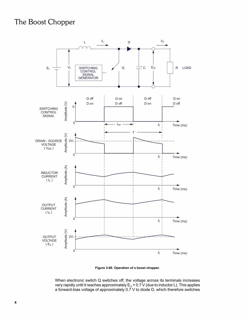
Figure 3-66 shows a boost chopper built with an electronic switch (Q) and adiode (D), and some waveforms related to this circuit. When electronic switch Qswitches on, the voltage across its terminals becomes virtually null, the DC powersupply voltage (EI) is applied to the inductor (L), and the current flowing in inductor L(IL) starts to increase. Simultaneously, diode D switches off since it becomesreverse-biased. At this moment, capacitor C starts to discharge into the load andboth the output current (IO) and voltage (EO) start to decrease.
The Boost Chopper
4
Figure 3-66. Operation of a boost chopper.
When electronic switch Q switches off, the voltage across its terminals increasesvery rapidly until it reaches approximately EO + 0.7 V (due to inductor L). This appliesa forward-bias voltage of approximately 0.7 V to diode D, which therefore switches
The Boost Chopper
5
on. At this moment, a current equal to IL ! IO starts to charge up capacitor C, andboth EO and IO start to increase.
The DC voltage at the boost chopper output (EO) is proportional to the DC voltageat the boost chopper input (EI) and the time the electronic switch is on during eachcycle. This time, which is referred to as the on-time (tON), is in turn proportional to theduty cycle α of the switching control signal applied to the control signal input ofelectronic switch Q. The equation relating voltages EO and EI is given by theexpression:
Thus, voltage EO can be varied by varying the duty cycle α. This equation indicatesthat voltage EO can range between voltage EI and an infinite voltage when the dutycycle α varies between 0 and 100%. In practice, however, the duty cycle α onlyapproaches 0 and 100%. Therefore, voltage EO can vary between a voltage a littlehigher than voltage EI and many times voltage EI. In certain circuits, however, themaximum value of the duty cycle α must be limited to limit the maximum voltage theboost chopper can produce.
Varying the frequency of the switching control signal while maintaining the dutycycle α constant does not vary the DC voltage and current at the boost chopperoutput (EO and IO). However, the ripple on the output voltage decreases as thefrequency of the switching control signal increases.
The power which the boost chopper delivers at its output (PO) is equal to the powerit receives at its input (PI) minus the power dissipated in the electronic switch and theinductor. The power dissipated in the electronic switch and the inductor is usuallysmall compared to the power PO. The power efficiency of boost choppers, thus, oftenexceeds 80%. Notice that the power efficiency is the ratio of the output power on theinput power times 100%, as stated in the following equation:
Procedure summary
In the first part of this exercise, you will set up the equipment required to perform thisexercise.
In the second part, you will use the circuit shown in Figure 3-67 to observe theoperation of a boost chopper. In this circuit, the boost chopper output is connectedto a resistive load consisting of resistors R2 and R3 connected in series.
You will vary the duty cycle of the switching control signal while observing theDC voltage and current at the boost chopper output. This will allow you to verify therelationship between the duty cycle and the DC voltage at the boost chopper inputand output, and to determine the direction of power flow.
In the third part, you will vary the frequency of the switching control signal whileobserving the DC voltage and current, as well as the voltage waveform, at the boostchopper output. This will allow you to verify the effect of frequency on theseparameters.
The Boost Chopper
6
In the fourth part, you will determine the power at the input and output of the boostchopper. You will then compare the output power to the input power and determinethe power efficiency of the chopper.
EQUIPMENT REQUIRED
Refer to the Equipment Utilization Chart, in Appendix C of this manual, to obtain thelist of the equipment required to carry out this exercise.
PROCEDURE
CAUTION!
High voltages are present in this laboratory exercise! Do not makeor modify any banana jack connections with the power on unlessotherwise specified!
Setting up the Equipment
G 1. Install the Enclosure / Power Supply, Power Supply, Chopper / Inverter,Smoothing Inductors, Resistive Load (2), and Data Acquisition Interfacemodules in the Mobile Workstation.
Install the Chopper / Inverter Control Unit in the Enclosure / Power Supply.
Plug the Enclosure / Power Supply line cord into a wall receptacle. Set thepower switch of the Enclosure / Power Supply to I (on).
G 2. On the Power Supply, make sure that the main power switch is set to O (off)and the voltage control knob to 0%.
Make sure that the Power Supply is connected to a three-phase powersource.
G 3. Make sure that the USB port cable from the computer is connected to theDAI module.
Connect the Low Power Inputs of the DAI and Chopper / Inverter modulesto the 24-V ac output of the Power Supply.
On the Power Supply, set the 24-V ac power switch to I (on).
G 4. Open the LVDAM-EMS Oscilloscope window.
The Boost Chopper
7
Operation of the Boost Chopper
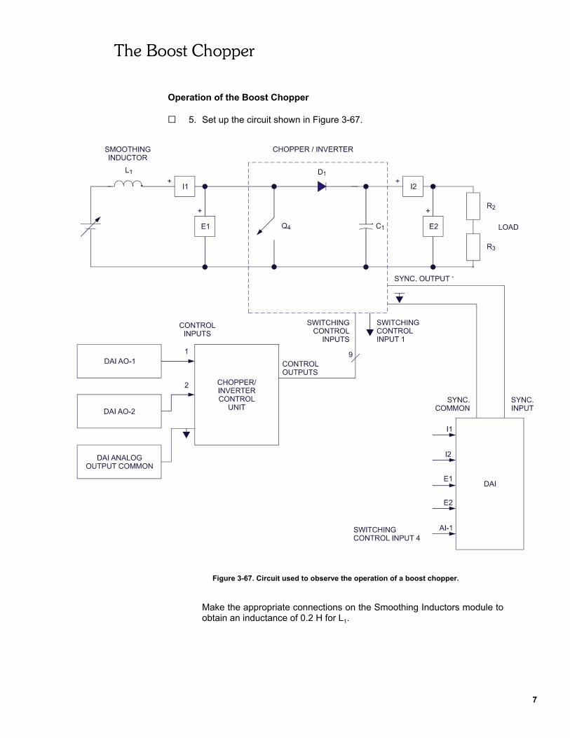
G 5. Set up the circuit shown in Figure 3-67.
Figure 3-67. Circuit used to observe the operation of a boost chopper.
Make the appropriate connections on the Smoothing Inductors module toobtain an inductance of 0.2 H for L1.
The Boost Chopper
8
Note: Diode D1 is the power diode connected in parallelwith electronic switch Q1. Diode D4 (connected in parallel withelectronic switch Q4) and electronic switch Q1 are not shown inthe figure because they are not used in this circuit. Electronicswitch Q1 is forced to the off state by connecting SWITCHINGCONTROL INPUT 1 to the common point.
G 6. Make the following settings:
On the Chopper / Inverter Control Unit
MODE . . . . . . . . . . . . . . . . . . . . . . . . . . . . . . . . . . . CHOP. PWM
On the Chopper / Inverter module
Switch S1 . . . . . . . . . . . . . . . . . . . . . . . . . . . . . . . . lower position
In the Oscilloscope window
Display E1, E2, AI-1, and I2 on Ch1, Ch2, Ch3, and Ch4.Ch1 Vertical Scale Setting . . . . . . . . 100 V/Div. (DC coupling)Ch2 Vertical Scale Setting . . . . . . . . 100 V/Div. (DC coupling)Ch3 Vertical Scale Setting . . . . . . . . . . 2 V/Div. (DC coupling)Ch4 Vertical Scale Setting . . . . . . . . 0.1 A/Div. (DC coupling)Time Base . . . . . . . . . . . . . . . . . . . . . . . . . . . . . . . . . 1 ms/div.Trigger Source . . . . . . . . . . . . . . . . . . . . . . . . . . . . . Ext. Sync.
In the LVDAM-EMS application
Analog Output AO-1 . . . . . . . . . . . . . . . . . . . . . . . . . . . . . . +10 VAnalog Output AO-2 . . . . . . . . . . . . . . . . . . . . . . . . . . . . . . . . 0 V
G 7. Set the Resistive Load modules to obtain a resistance of 400 Ω for R2 andR3.
G 8. On the Power Supply, set the main power switch to I (on), then set thevoltage control knob to 20%.
Note: Select convenient vertical scale and position settings in theOscilloscope window to facilitate observation.
Set Analog Output AO-2 so that two complete cycles of the switching controlsignal coincide as closely as possible with the full width of the Oscilloscopewindow. This sets the period of the switching control signal to approximately5 ms. Consequently, the operating frequency of the boost chopper isapproximately 200 Hz.
Set Analog Output AO-1 so that the duty cycle of the switching control signalis approximately 80% while observing the DC voltage at the boost chopperoutput in the AVG column of the Waveform Data box in the Oscilloscopewindow.
The Boost Chopper
9
Note: Notice that the duty cycle of PWM control signals 2 and 4varies linearly from 0.95 to 0.05 as the voltage applied toCONTROL INPUT 1 varies from -10 to +10 V when the Chopper /Inverter Control Unit in the CHOP. PWM mode.
G 9. Print or save the waveforms displayed in the Oscilloscope windowas OW391.
They represent the supply voltage (EI on Ch1), the voltage across the loadconnected to the boost chopper output (EO on Ch2), the switching controlsignal applied to electronic switch Q4 (Ch3), and the load current (IO onCh4).
G 10. Describe how the DC voltage at the boost chopper output varies when theduty cycle of the switching control signal is increased.
G 11. Briefly explain why the boost chopper can produce output voltages whichare much higher than the voltage applied at its input.
G 12. Set Analog Output AO-1 so that the duty cycle of the switching control signalis approximately 5% (minimum value).
Print or save the waveforms displayed in the Oscilloscope windowas OW392.
G 13. Compare the DC voltage at the boost chopper output (Ch2) with theDC voltage provided to the boost chopper (Ch1) (shown in the AVG columnof the Waveform Data box).
Explain why this circuit is referred to as a boost chopper, knowing that theduty cycle of the switching control signal is set to minimum.

The Boost Chopper
10
G 14. Compare the DC voltages at the boost chopper output for both duty cyclevalues: 5 and 80%. Do your observations confirm that the DC voltage at theboost chopper output increases as the duty cycle of the switching controlsignal is increased?
G Yes G No
G 15. Set Analog Output AO-1 so that the duty cycle of the switching control signalincreases from 5 to 80% while observing the load current (Ch4).
Does the polarity of the load current change as the duty cycle of theswitching control signal increases from 5 to 80%?
G Yes G No
In which direction does the power flow?
G 16. Record the supply voltage (EI) shown in the AVG column (Ch1) of theWaveform Data box.
Supply voltage EI =
G 17. Calculate the DC voltage which should appear at the output of the boostchopper using the following equation (α = 80%):
G 18. Record the output voltage EO shown in the AVG column (Ch2) of theWaveform Data box.
Measured output voltage EO =
Note: The difference between the calculated and measured valueis caused by the voltage drops in the inductor and in theelectronic switch.
The Boost Chopper
11
Observing the Effect of the Switching Control Signal Frequency
G 19. Make the following settings in the Oscilloscope window:
Display E1, E2, I1, and I2 on Ch1, Ch2, Ch3, and Ch4.Ch1 Vertical Scale Setting . . . . . . . . . . 100 V/Div. (DC coupling)Ch2 Vertical Scale Setting . . . . . . . . . . 100 V/Div. (DC coupling)Ch3 Vertical Scale Setting . . . . . . . . . . . . 1 A/Div. (DC coupling)Ch4 Vertical Scale Setting . . . . . . . . . . . . 1 A/Div. (DC coupling)Time Base . . . . . . . . . . . . . . . . . . . . . . . . . . . . . . . . . . . 2 ms/div.Trigger Source . . . . . . . . . . . . . . . . . . . . . . . . . . . . . . Ext. Sync.
G 20. Make sure that the duty cycle of the switching control signal is set to 80%.
Make sure that the voltage control knob on the Power Supply is set to 20%.
Slowly vary the voltage applied to Control Input 2 from -10 to +10 V to varythe frequency of the switching control signal, while observing the averagevoltage and current at the buck chopper output (shown in the AVG column(Ch2 and Ch4) of the Waveform Data box).
Does the frequency of the switching control signal have a significant effecton the average voltage and current the buck chopper provides? If so,describe this effect.
G 21. Set the voltage applied to Control Input 2 to obtain a minimum frequency ofthe switching control signal.
Print or save the waveforms displayed in the Oscilloscope windowas OW393.
G 22. Slowly vary the voltage applied to Control Input 2 from -10 to +10 V to varythe frequency of the switching control signal, while observing the waveformof the current at the boost chopper input in the Oscilloscope window (Ch3).
Does the frequency of the switching control signal have a significant effecton the ripple of the current at the boost chopper input? If so, describe thiseffect.

The Boost Chopper
12
Set the voltage applied to Control Input 2 to obtain a maximum frequencyof the switching control signal.
Print or save the waveforms displayed in the Oscilloscope windowas OW394.
Output Power Versus Input Power
G 23. Set Analog Output AO-2 to +10 V.
Make sure that the duty cycle of the switching control signal is still set to80%.
Using the DC voltage and current supplied by the variable-voltageDC power supply to the buck chopper, calculate the power (PI) which issupplied to the boost chopper. Record the resulting power in the followingblank space.
Power supplied to the boost chopper PI =
G 24. Using the DC voltage and current supplied by the buck chopper to the load,calculate the power (PO) which is supplied to the load. Record the resultingpower in the following blank space.
PO =
G 25. Calculate the power efficiency of the boost chopper using the followingequation:
G 26. Is the power at the output of the boost chopper nearly equal to the power atits input?
G Yes G No
G 27. On the Power Supply, set the voltage control knob to 0%, then set the mainpower switch and the 24-V ac power switch to O (off). Set the power switchon the Enclosure / Power Supply to O (off). Remove all leads and cables.
CONCLUSION
In this exercise, you verified that the DC voltage at the boost chopper outputincreases as the duty cycle of the switching control signal is increased. You foundthat the minimum DC voltage that can be obtained at the boost chopper output isslightly higher than the DC voltage at its input.

The Boost Chopper
13
You saw that power always flows in the same direction in a boost chopper. Youobserved that the frequency of the switching control signal has no effect on theDC voltage and current provided by the boost chopper. Nevertheless, you saw thatas the frequency of the switching control signal increases, the ripple on the inputcurrent of the boost chopper decreases. You verified that the power at the boostchopper output is approximately equal to the power at its input.
REVIEW QUESTIONS
1. Describe the effect the switching control signal frequency has on the outputvoltage and current of a boost chopper.
2. A boost chopper is powered by a 12-V dc power supply. What is the outputvoltage range of this chopper if the duty cycle can vary between 20 and 95%?
3. Briefly describe the operation of the boost chopper.
4. Explain why the maximum value of the duty cycle must be limited in certainboost choppers.
5. Name the component operating with AC power which best compares to theboost chopper.


Instructor Guide
Sample Exercise
Extracted from
Asynchronous and
Doubly-Fed Generators

Asynchronous and Doubly-Fed Generators
17
EXERCISE 3-11 THE FOUR-QUADRANT CHOPPER
ANSWERS TO PROCEDURE STEP QUESTIONS
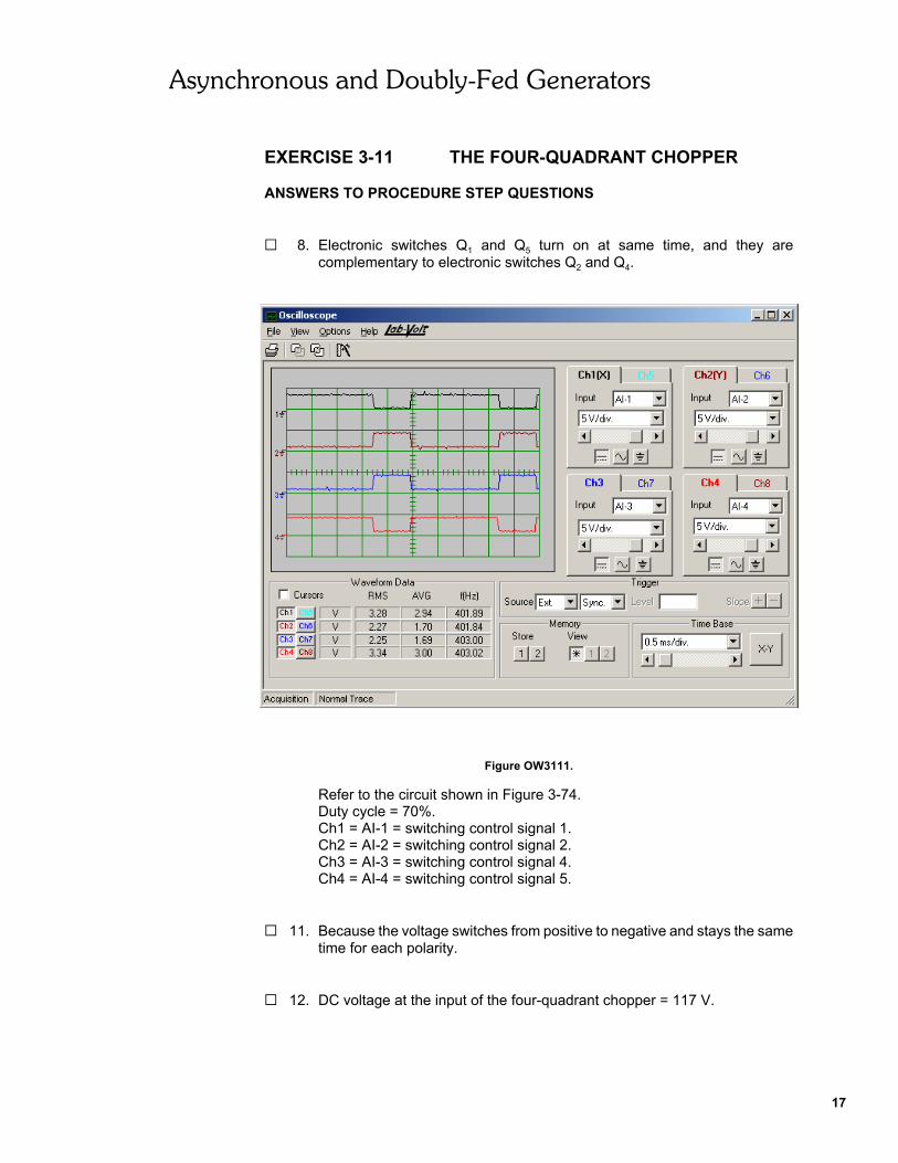
G 8. Electronic switches Q1 and Q5 turn on at same time, and they arecomplementary to electronic switches Q2 and Q4.
Figure OW3111.
Refer to the circuit shown in Figure 3-74.Duty cycle = 70%.Ch1 = AI-1 = switching control signal 1.Ch2 = AI-2 = switching control signal 2.Ch3 = AI-3 = switching control signal 4.Ch4 = AI-4 = switching control signal 5.
G 11. Because the voltage switches from positive to negative and stays the sametime for each polarity.
G 12. DC voltage at the input of the four-quadrant chopper = 117 V.
Asynchronous and Doubly-Fed Generators
18
Figure OW3112.
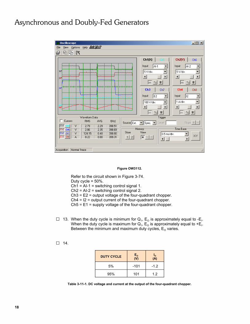
Refer to the circuit shown in Figure 3-74.Duty cycle = 50%.Ch1 = AI-1 = switching control signal 1.Ch2 = AI-2 = switching control signal 2.Ch3 = E2 = output voltage of the four-quadrant chopper.Ch4 = I2 = output current of the four-quadrant chopper.Ch5 = E1 = supply voltage of the four-quadrant chopper.
G 13. When the duty cycle is minimum for Q1, EO is approximately equal to -EI.When the duty cycle is maximum for Q1, EO is approximately equal to +EI.Between the minimum and maximum duty cycles, EO varies.
G 14.
DUTY CYCLE EO(V)
IO(A)
5% -101 -1.2
95% 101 1.2
Table 3-11-1. DC voltage and current at the output of the four-quadrant chopper.
Asynchronous and Doubly-Fed Generators
19
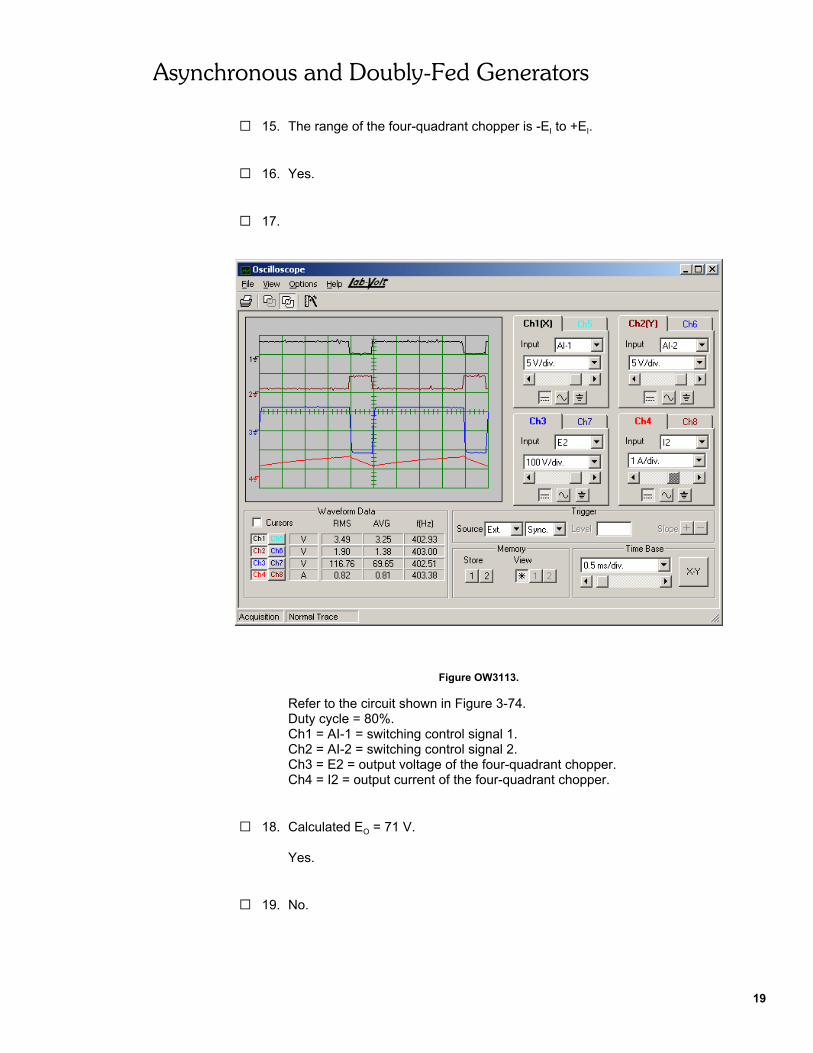
G 15. The range of the four-quadrant chopper is -EI to +EI.
G 16. Yes.
G 17.
Figure OW3113.
Refer to the circuit shown in Figure 3-74.Duty cycle = 80%.Ch1 = AI-1 = switching control signal 1.Ch2 = AI-2 = switching control signal 2.Ch3 = E2 = output voltage of the four-quadrant chopper.Ch4 = I2 = output current of the four-quadrant chopper.
G 18. Calculated EO = 71 V.
Yes.
G 19. No.

Asynchronous and Doubly-Fed Generators
20
G 26.
Figure G3111.
Refer to the circuit shown in Figure 3-75.Ch1 = AI-1 = output current of the four-quadrant chopper.Ch2 = AI-2 = output voltage of the four-quadrant chopper.

Asynchronous and Doubly-Fed Generators
21
G 30.
Figure G3112.
Refer to the circuit shown in Figure 3-75.Ch1 = AI-1 = output current of the four-quadrant chopper.Ch2 = AI-2 = output voltage of the four-quadrant chopper.
G 31. Because it is a reversible chopper in voltage and in current (it operates inthe four quadrants).
G 32. In quadrants 2 and 4.
ANSWERS TO REVIEW QUESTIONS
1. When electronic switches Q1 and Q5 are on, EI is applied to the load and whenQ2 and Q4 are on, -EI is applied to the load. If the duty cycle is greater than 50%for Q1, the average output voltage will be positive and if the duty cycle is lessthan 50%, the average output voltage will be negative.
2. Yes.
3. The four-quadrant operation can provide a positive or a negative DC voltageregardless of the direction in which the current flows.

Asynchronous and Doubly-Fed Generators
22
4. The equation relating voltages EO and EI is EO = EI x (2αQ1 - 1).So -24 = 200 x (2αQ1 - 1) = 56%.
5. The output voltage is reversible.

BibliographyJackson, Herbert W. Introduction to Electric Circuits, 5th edition, New Jersey: Prentice Hall, 1981ISBN 0-13-481432-0
Wildi, Theodore. Electrical Machines, Drives, and Power Systems, 2nd edition,New Jersey: Prentice Hall, 1991.ISBN 0-13-251547-4