Asteroid Origins Satellite (AOSAT) I: An On-orbit...
41
Asteroid Origins Satellite (AOSAT) I: An On-orbit Centrifuge Science Laboratory Jack Lightholder*, Andrew Thoesen*, Eric Adamson, Jeremy Jakubowski, Ravi Nallapu, Sarah Smallwood, Laksh Raura, Andrew Klesh, Erik Asphaug, Jekan Thangavelautham Arizona State University, Tempe, AZ 85287 Abstract Exploration of asteroids, comets and small moons (‘small bodies’) can an- swer fundamental questions relating to the formation of the solar system, the availability of resources, and the nature of impact hazards. Near-earth aster- oids and the small moons of Mars are potential targets of human exploration. But as illustrated by recent missions, small body surface exploration remains challenging, expensive, and fraught with risk. Despite their small size, they are among the most extreme planetary environments, with low and irregu- lar gravity, loosely-bound regolith, extreme temperature variation, and the presence of electrically charged dust. Here we describe the Asteroid Origins Satellite (AOSAT-I), an on-orbit, 3U CubeSat centrifuge using a sandwich- sized bed of crushed meteorite fragments to replicate asteroid surface con- ditions. Demonstration of this CubeSat will provide a low-cost pathway to physical asteroid model validation, shed light on the origin and geophysics of asteroids, and constrain the design of future landers, rovers, resource ex- tractors, and human missions. AOSAT-I will conduct scientific experiments within its payload chamber while operating in two distinct modes: 1) as a nonrotating microgravity laboratory to investigate primary accretion, and 2) as a rotating centrifuge producing artificial milligravity to simulate surface conditions on asteroids, comets and small moons. AOSAT-I takes advantage of low-cost, off-the-shelf components, modular design, and the rapid assem- bly and instrumentation of the CubeSat standard, to answer fundamental questions in planetary science and reduce cost and risk of future exploration. Keywords: CubeSat, Centrifuge, Asteroids, Laboratory Preprint submitted to Acta Astronautica January 6, 2017
Transcript of Asteroid Origins Satellite (AOSAT) I: An On-orbit...

Asteroid Origins Satellite (AOSAT) I: An On-orbit
Centrifuge Science Laboratory
Jack Lightholder*, Andrew Thoesen*, Eric Adamson, Jeremy Jakubowski,Ravi Nallapu, Sarah Smallwood, Laksh Raura, Andrew Klesh,
Erik Asphaug, Jekan Thangavelautham
Arizona State University, Tempe, AZ 85287
Abstract
Exploration of asteroids, comets and small moons (‘small bodies’) can an-swer fundamental questions relating to the formation of the solar system, theavailability of resources, and the nature of impact hazards. Near-earth aster-oids and the small moons of Mars are potential targets of human exploration.But as illustrated by recent missions, small body surface exploration remainschallenging, expensive, and fraught with risk. Despite their small size, theyare among the most extreme planetary environments, with low and irregu-lar gravity, loosely-bound regolith, extreme temperature variation, and thepresence of electrically charged dust. Here we describe the Asteroid OriginsSatellite (AOSAT-I), an on-orbit, 3U CubeSat centrifuge using a sandwich-sized bed of crushed meteorite fragments to replicate asteroid surface con-ditions. Demonstration of this CubeSat will provide a low-cost pathway tophysical asteroid model validation, shed light on the origin and geophysicsof asteroids, and constrain the design of future landers, rovers, resource ex-tractors, and human missions. AOSAT-I will conduct scientific experimentswithin its payload chamber while operating in two distinct modes: 1) as anonrotating microgravity laboratory to investigate primary accretion, and 2)as a rotating centrifuge producing artificial milligravity to simulate surfaceconditions on asteroids, comets and small moons. AOSAT-I takes advantageof low-cost, off-the-shelf components, modular design, and the rapid assem-bly and instrumentation of the CubeSat standard, to answer fundamentalquestions in planetary science and reduce cost and risk of future exploration.
Keywords: CubeSat, Centrifuge, Asteroids, Laboratory
Preprint submitted to Acta Astronautica January 6, 2017

1. Introduction
Spacecraft missions to asteroids, comets and small moons are driving ad-vances toward answering fundamental questions regarding the physics andchemistry of solar system formation, and the origins of organic molecules,the building blocks of life. Geophysical studies of cratering and dynamicalprocesses on near-Earth asteroids improve collision mitigation efforts thatsafeguard the Earth. Addressing these and other important questions re-quires exploration and in situ sampling from the surfaces and interiors ofsmall bodies, as called out in the NRC Decadal Survey [1]. However, surfaceexploration of comets, moons and asteroids is a daunting challenge, as evi-denced by the Hayabusa [2], Philae [3], Phobos [4] and NEAR [5] missionsand the difficulties they faced. Today there are two missions in cruise phaseto small asteroids, the Hayabusa-2 mission and the OSIRIS-REx mission,both to perform touch and go sampling operations.
Hayabusa-2 will include several surface science experiments including thefiring of a 2-kg projectile at 2 km/s to make a several-meter crater [6]. Theera of landed investigations on asteroids will commence when Hayabusa-2deploys the DLR MASCOT lander [7] and the Minerva-2 small robotic pay-loads [8]. Designing for surface operations is deeply challenged by the widerange of operational conditions possible with the largely unknown surfaceproperties. Proposed flagship investigations like the Asteroid Retrieval Mis-sion (ARM) rely on some understanding of the mechanical behaviors andgeologic structural conditions to be expected in milligravity, that is, gravita-tional accelerations around 1/1000 that of Earth. Are the surfaces of smallbodies rigid, or as soft and fluid as quicksand? These and other questionsmust be answered in order to develop refined models and low-risk opera-tional strategies. Additionally, for most asteroids and other small bodies ofinterest, in addition to milligravity their surfaces consist of fine debris andcoarse debris, possibly a global ‘rubble pile’ constitution, and diurnal cyclesof hours with associated extreme changes in temperature. The environmentcan be highly dynamic, and much more alien than the Moon. Grappling oranchoring onto the surface of a small body presents a major challenge. Thedevelopment of relevant technologies, enabling successful asteroid landings,as well as extending surface exploration missions, requires the refinementof our existing physical models of the relevant surface and near-surface en-vironments, which, in turn, will guide the design and development of nextgeneration landers.
2

Missions to asteroids and comets remain expensive, long duration en-deavors, fraught with high-risk. A credible risk mitigation step is to recreateasteroid and comet environments inside a laboratory. It is feasible to gen-erate low-gravity environments on Earth, for instance, by using buoyancymethods, air tables, drop towers and parabolic flights. While missions likeBORE (Box of Rocks Experiment) do exist[9], these methods have impor-tant limitations. Low-gravity phenomena may be simulated by submersionin fluids, but the reduction of the earth’s gravitational attraction is limitedto the magnitude of buoyancy. Air tables may be used to simulate low grav-ity conditions, but this method confines interactions to two-dimensions. ISSposseses a small centrifuge system that focuses on Biology and Microbiol-ogy experiments ranging from micro-g to 1-g. Additionally, drop towers andparabolic flights produce very low gravity environments; however these areonly for short timescales of 5-15 seconds. All of these options are limited,either not sufficiently representative of asteroid surface physics, or else justa brief window into that environment.
A credible alternative for long-term laboratory research of small bodies isto simulate milligravity geological conditions inside a centrifuge laboratoryin Low Earth Orbit (LEO). As noted in Section 2, proposals for centrifugesin space are not new (see for instance, [10, 11]). However, previous centrifugeconcepts were designed for human habitats or manufacturing and process-ing, often consisting of a rotating spacecraft, connected to a stationary one.Such a design poses significant challenges [12] as it requires the impositionof a counter-spin to ensure parts of the spacecraft remain stationary, thusrequiring large, custom-designed, persistent reaction wheels. At the other ex-treme, a small sample-separation centrifuge to spin test-tubes to high-g hasbeen installed by Nanoracks onboard the ISS. Accessing the middle-groundof low-but-nonzero gravity has so far not been possible.
We propose a simplified centrifuge laboratory for simulating small bod-ies such as asteroids using a low-cost 3U CubeSat [13, 14]. The entire 3Uspacecraft is designed to spin about its system chamber while carrying alarge payload chamber containing crushed meteorites (regolith), which arethe remnants of asteroids. A centrifuge spinning at low angular velocity willsimulate the gravity expected on these small bodies. The advantage of thisapproach is that it enables the simulation of asteroid and comet surface condi-tions without requiring the mission costs associated with in situ explorationof such interesting bodies. This laboratory will facilitate the developmentand testing of new technologies offering rapid turn-around time for relatively
3

low cost.Herein, we present a detailed discussion of the design and instrumentation
of AOSAT I, which will be the first space centrifuge for studying milligravityenvironments. Our current work focuses on investigating the concept fea-sibility, system design, deployment mechanism and power requirements oflaunching and operating a 3U (3000 cm3) CubeSat centrifuge system in or-bit. The spacecraft includes a 2U experimental chamber containing regolith,enabling scientific experiments within its payload chamber while operatingin two distinct modes: 1) a centrifuge producing artificial gravity to simulatesurface conditions on asteroids of < 1 km diameter, and 2) as a stationarymicrogravity laboratory to investigate primary accretion. These experimentswill advance knowledge of planet formation and surface properties of aster-oids. Within the payload are several instruments including a camera array,lights, shaker platform and a bead deployer (for investigating impact dynam-ics). The remaining 1U partition contains the spacecraft computer, commu-nications systems, and attitude determination and control system. Majordesign challenges related to spacecraft stability must be overcome due tothe shifting regolith within the relatively large experimental chamber. Theproposed system illustrates the effective use of low-cost, off-the-shelf com-ponents in the rapid assembly and instrumentation of a CubeSat sciencelaboratory. Demonstration of this CubeSat will provide a low-cost pathwayto physical asteroid physics model validation, shed light on asteroid origins,and constrain the design of future asteroid surface probes.
In Section 2 we present background on particle aggregation physics inmicrogravity, as well as the use of centrifuges to produce “artificial gravity”,followed by a detailed discussion of the design of AOSAT I in Section 3.Section 4 describes physical and numerical models that were employed toconstrain the system design and to analyze operation of critical mechanisms.The implications of these results on overall system performance are discussedin detail within Section 5 and conclusion are summarized in Section 6.
2. Background
The scientific goals of the AOSAT I mission are two-fold: 1) investigatethe process of particle coagulation in microgravity (close to zero-g), and 2)model the near-surface milligravity (∼ 10−3 g⊕ ∼ 1 cm s−2) characteristics ofsmall asteroids, where g⊕ is Earth gravity. In addition to performing ground-breaking asteroid science, the successful demonstration of this first on-orbit
4

spacecraft centrifuge will enable advanced future missions that will furtherilluminate fundamental aspects of the early formation of planetary bodies,and will provide detailed experimentally-derived knowledge of the physicalproperties of asteroid surface and sub-surface environments and operationstherein.
2.1. Particle Aggregation
Planets are formed in protoplanetary disks as a result of star formation.Within protoplanetary disks, dust coalesces to planetesimals, a vital stepin the planet formation process. However, this coalescence process is notwell understood [15]. Multiple hypotheses exist regarding the relevant pa-rameters which may lead to particle aggregation in space, and this has beenassessed in various ways. Brisset et al. [16] studied dust aggregate collisionbehavior on the suborbital rocket flight REXUS 12 to further understandthe mechanisms behind the first phase of planet formation. Onboard theInternational Space Station, Love et al. [17] investigated particle aggregationof various types and sizes of angular sub-millimeter particulate. Marshallet al. [18] preferentially chose sub-millimeter quartz and volcanic ash par-ticulate to fly in microgravity aboard Space Shuttle Columbia in a chamberenvironment (ensuring particle suspension) in order to observe coagulation.Dust synthesis and modeling has been done in laboratory conditions in orderto understand the morphology of grain growth to constrain future models ofprimary planetary accretion by Praburam and Goree [19].
We propose to directly observe granular coagulation processes for periodsof up to 15 hours within the AOSAT I microgravity laboratory. We will im-age the regolith in zero-gravity, while the spacecraft is not spinning, and thenapply the spacecraft flywheel torque to mobilize and gather the material, ina series of experiments that can be compared with and validate model pre-diction. A single science chamber of 19.2 cm will be utilized within AOSATI. The science chamber will contain ∼ 0.3 kg of Tamdakht meteorite material[20] an H5 ordinary chondrite, with a range of particle sizes approximatelyfitting a cumulative size distribution n(d) ∝ d−3. For AOSAT-I these par-ticles will be sieved to mm-sizes to avoid the complexities associated withimaging a dust-laden experiment, focusing on the granular physics of thecoagulation process.
5

2.2. Asteroid Surface Geophysics
The primary, novel experiments of AOSAT-I will be to study asteroidsurface geophysics, as it will be the first space centrifuge for studying mil-ligravity environments. These experiments are fundamentally to watch whathappens when various forces (rotations and vibrations) are applied to a bedof airless meteorite regolith particles, forces that will be closely analogous tothose representative of the surface conditions of small asteorids.
The concept of utilizing rotational motion to simulate gravitational ac-celeration in space was first proposed by Konstantin Tsiolkovsky just priorto the turn of the 20th century [21]. A thorough investigation of the de-tails related to such a space based centrifuge apparatus was presented byTheodore Hall in his doctoral dissertation [22]. Though this concept hasseen great popularity in science fiction since its inception, spaceborne exper-iments have been sparse. The first occurred during the Gemini 11 missionin 1966 [23]. This experiment required tethering the Gemini 11 spacecraftto its Agena Target Vehicle by a 30 m tether and initiating a rotation ofapproximately 0.15 revs/min. The resulting artificial gravity is estimated tohave been approximately 1.5 × 10⁻⁴ g (where g = 9.81 m/s2 is the gravita-tional acceleration at the surface of the earth). Neither astronaut on boardthe spacecraft was able to detect such a small force, however, the astronautsobserved a camera resting on the instrument panel to accelerate toward theouter wall of the craft, parallel to the tether.
Since the Gemini 11 mission, significant work has focused on TetheredSatellite Systems (TSS) (for detailed reviews see [24], [25] and [26]), fromrelatively simple two-body dumbbell configurations, conceptually similar tothe Gemini 11 experiment, to triangular [27], wheel-and-spoke [28] and morecomplicated configurations consisting of numerous spacecraft. Such TSSs of-fer great potential for space research focusing on the generation of electricity,artificial gravity, and upper atmospheric research. However, these systemsalso pose significant challenges, particularly in terms of spacecraft stability.
Centrifuge concepts from 1950s and 1960s generated numerous proposalsfor spinning space colonies (Figure 1). More practical attempts at develop-ing centrifuges include the Centrifuge Accommodation Module (CAM), de-veloped by the Japanese Aerospace Exploration Agency (JAXA) and whichwas to be operated by NASA. The CAM was intended to be used to con-duct various biological and life-science related experiments, providing be-tween 0.01 g to 2 g [29, 30]. It is significant to note that this chamber would
6

have facilitated operation at two distinct values of artificial gravity (i.e., an-gular velocity). A more ambitious centrifuge concept was proposed fromNASA’s Johnson Space Center (JSC) in 2011 [31], consisting of an inflatablecentrifuge attached to the International Space Station (ISS). The attachedcentrifuge would have provided the sleeping module for the ISS crew. Thiscentrifuge was intended to be a low-cost demonstration for a multi-missionmanned space exploration vehicle, NAUTILUS-X, that would be placed at L1and operate as a staging ground/living quarters for subsequent missions toMars and beyond. Small-scale centrifuges have also been developed for appli-cations focusing on microbiology research in space at the cellular/molecularlevel [32]. In 2004, we proposed the development CubeSat-sized centrifugesin space to simulate milligravity conditions to 1 g for a range of applica-tions including planetary science to life science and in-space manufacturing[13, 14].
Figure 1: Artist Concept of a Spinning Space Colony (courtesy of Mark Tims).
AOSAT-I is the first spacecraft centrifuge for studying milligravity envi-ronments, and in fact will be the first whole-spacecraft research centrifuge.It achieves this goal by looking at small gravitational forces common to anasteroid, which are typically 1/1000 that of Earth. If one sets the centripetalacceleration rω2 equal to the gravitational acceleration GM/R2 where r isthe radius of the centrifuge (approx. 17 cm for AOSAT-I, from the centerof mass to the center of the regolith bed) and where M and R are the massand radius of a spherical, non-rotating asteroid of uniform density ρ (thereare no such things, but this is an approximation), then ω =
√4/3πGρR/r.
Measuring ω in rpm (revolutions per minute) and R in km, and assuming
7

ρ = 2 g cm−3 one obtains the approximation ωrpm = 0.55√Rkm. Therefore
spacecraft rotations with an order of magnitude of 1 rpm is perfect for study-ing asteroid surface gravity conditions, for bodies 0.1 to 10 km in radius (e.g.small-NEO to Phobos-sized). There is no lower limit to ω, but we consider4 rpm to be a safe upper limit. Stability at higher rpm will be evaluated inflight, at the end of mission.
AOSAT-I is designed to obtain stable CubeSat rotations of 0-4 rpm us-ing a flywheel for the primary spin axis, stabilized by magnetically inducedtorques. These are slow rotations, but as we shall see one of the challengesin designing AOSAT I is to prove that this is a stable experimental con-figuration, within the tolerances of the experiment. We note therefore thatabsolute, constant asteroid-like gravity conditions are not the requirement.After all, the centripetal acceleration some distance closer to the spin axis,will be lower than the acceleration at the ‘bottom’ of the lab chamber, so wecannot achieve constant gravity. Moreover, any nutation of the spacecraftduring its rotation will cause the regolith bed to feel accelerations to the leftand right, per rotation. While these irregularities must be guarded against,primarily to prevent destabilization of the spacecraft (tumbling), they arenot problematic from the point of view of the milligravity experimentation,since part of the study is to understand the stability of asteroid land-formsto various kinds of stresses, and this would be an oscillatory stress.
All of these data will be used to validate high definition simulations ofgranular physics on and beneath the surfaces of small planetary bodies –whose gravity itself is irregular, and oscillatory. A typical small NEO spinswith a period as fast as a few hours, or faster, and can have surface (effective)gravity varying by a factor of 2-3 from location to location, and changingconsiderably with depth. So nutations and other sources of accelerationinside of the AOSAT-I lab chamber need to be monitored and understoodand tracked, for modeling purposes, but do not need to be eliminated.
3. System Design
3.1. Concept of Operations
The system is centered around an experiment consisting of 300 g ofmeteorite fragments, that are subjected to various external and internalforces: spacecraft rotations, tunable vibrations, and various forms of inter-particulate and particle-spacecraft cohesion. The supporting infrastructureof AOSAT-I is designed to observe the behavior of this material, providing
8

a flat and measured chamber (to facilitate observation and interpretation),banks of LEDs for variable kinds of illumination, tunable buzzers, and stereocameras.
The regolith is produced by pounding and crushing pieces of the H5 ordi-nary chondrite meteorite Tamdakht, sieved into a cumulative size distributionwith exponent -2 to -3 and a smallest grain diameter 2 mm, and then sealedbehind the launch-door of the payload chamber. The meteorite fragmentsare produced in other experiments (strength-to failure; ballistics) and are se-lected from an interior fragment of Tamdakht, approx. 9 kg total mass, thatwas never subject to atmospheric stresses or thermal heating upon Earth im-pact (no fusion crust). Fragments of Tamdakht have strength and hardnesscharacteristics similar to concrete [33]. The fragments are stored carefully,and after sieving are rinsed in methanol to remove any possible handlingresidues and to detach any sub-mm particulates; then they are dried un-der vacuum conditions prior to payload integration. (The engineering modelof the AOSAT-I lab chamber uses fragments of concrete, with comparablestrength and hardness, instead of meteorite.)
During the science phases, this asteroid-regolith payload will freely floatin a rectangular payload chamber 8.3 cm × 8.3 cm × 19.2 cm. Stereo camerasand banks of LEDs will be used to resolve discrete grains and image aggregateparticulate behavior. But the granular payload must be confined during lift-off, otherwise crushing vibrations and shaking would damage the grains andintroduce dust to the lab chamber. The stored behind a door during launch,to be opened once zero-g is established. The opening of this door begins thescience investigation, and the initial release of particles constitutes the firstexperiment.
Science operations consist of two phases: (1) release of regolith and track-ing of particles in the non-rotating spacecraft, to study aggregation of parti-cles to each other or to the walls; and (2) centrifuge experiments in a rotatingspacecraft mimicking asteroid surface conditions, to study regolith settlingand granular stability and aggregate behavior/flow.
3.1.1. Science Phase 1
The first phase begins when a single door mechanism (shown in Figure3) is deployed to release the regolith. A nichrome burn-wire door-releasemechanism is activated, allowing the door to come to a position flush withthe inner wall of the payload. By this time the fragments will have mostlyequilibrated to vacuum from the 1 bar payload environment, but might un-
9

dergo some final dehydration and degassing especially once released fromdense packing behind the door. Particle behavior will be analyzed twice,once as they tumble out of the door, and then 7 days later to observe theirfreely-floating configuration, to see if there are any changes related to particleequilibration.
Regolith aggregation will be monitored in the first stage using stereo cam-eras, during and after door deployment, and then in an experiment applyingthe buzzer to look for standing patterns forming in zero-gravity. Particleaggregation will be auto-detected on the basis of Shannon’s entropy of theimage frames. These key frames will be transmitted, and from those, thedesired sequences selected. As described in Section [BELOW] the choice ofa UHF-band transmitter for AOSAT-I forces us to be creative and selectivein the transmission of science data.
3.1.2. Science Phase 2
The second and primary phase of the AOSAT-I investigation is to mon-itor the regolith during a series of centrifuge experiments, and thereby toenable scientists and engineers to validate detailed models for the surfaceenvironment of asteroids, comets and small moons. Phase 2 is the novelexperimentation of AOSAT, which goes beyond ‘microgravity’, by which weusually mean ‘close enough to zero-gravity that it does not matter’, to ‘mil-ligravity’ by which we mean, ‘gravity that is large enough to matter, butonly if you have hours to find out’. This is the gravity that determines thegeology of small planetary bodies, and AOSAT-I offers the first facility toexplore it directly, apart from exploring the surfaces of asteroids themselvesin deep space.
3.2. Final Design
The proposed 3U Cubesat (see Figure 2) is designed for operation both inLow Earth Orbit (LEO) and Sun Synchronous Orbit. The spacecraft is builtupon a 3U Tyvak frame, functionally partitioned into two sections. A 1Ucompartment houses the satellite’s systems hardware including navigationsystems, computers, and communications hardware, while the second, longerchamber is an insertable payload comprising the experimental chamber andrequired instrumentation, mounted within the spacecraft frame.
The payload chamber has an 8.3 cm2 cross-section with a length of 19.2 cmand contains an experimental compartment and instrumentation compart-ment separated by borosilicate glass. The experimental compartment con-
10

Figure 2: Overview of AOSAT I design specifications.
tains the holding area for the regolith and the spring-loaded burnwire-activateddoor. The instrumentation compartment of the payload has three cameras,piezo-vibrators and LEDs. This payload does not utilize the full 10 cm2 cross-section of the satellite but instead is attached inside the frame by mountingbrackets due to considerations of structural integrity as well as requirementsrelated to the design of the scientific capabilities.
A high-level overview of system specifications is summarized in Table1. The mass, volume, and power budget are well within the bounds forCubeSats of this size as required by the Cubesat Design Specification (CDS)[34]. The CDS limits the maximum allowable mass of a 3U craft to 4 kg. Thelarge mass margin (∼ 25%) is attributable to the large hollow experimentalchamber required for the regolith experiment. The 9 W power obtained underthe sun.
A detailed mass budget for the spacecraft, itemized by subsystem, is pre-
11

Table 1: Overview of mission bounds
System SpecificationSystem 3U Cubesat ExperimentInstruments Stereo Cameras, Reference
Camera, Nitrogen BeadDeployer, Piezo Vibrators
Communications UHF, Simplex ModemMass 3050 gVolume 1300 cm3
Power 9 WPayload Mass 1250 gPayload Volume 450 cm3
Payload Peak Power 3.7 WLife 2 Years
sented in Table 2. Note the Chassis kit includes solar array and battery. Notethat 0.3 kg of the ∼ 1.3 kg payload mass is comprised of asteroid regolith.With such a large margin in the mass budget, the amount of regolith maybe adjusted to fit experimental needs. The spacecraft volume (itemized inTable 3) falls within a 61% margin due to the hollow chamber requirement.This provides for design flexibility in order to accommodate additional in-strumentation without detriment to experimental results.
The systems chamber contains the Tyvak Intrepid computer, includingwatchdog circuitry and power control, a Tyvak UHF communications daugh-terboard, attitude control instrumentation and an S-band communicationssystem. In addition, it contains a reaction-wheel for spinning the spacecraftand three magnetorquers. This allows the CubeSat to generate 1 rpm spinwhile preventing tumbling and wobbling. The spacecraft will use S-band ra-dio for downlinking science data and will have a maximum data throughputof 115200 bps.
Power will be supplied by the body-mounted photovoltaics and will chargea 37 Whr lithium ion battery. This design allows for all instrumentationand hardware required for spacecraft operations to be integrated within thesystems chamber.
One of the limiting factors in designing such systems becomes the totalpower generated by the solar cells. Power considerations are discussed in
12

Table 2: Itemized mass budget organized by subsystem
Subsystem Unit Mass(g) Uncert.% Mass* (g)Structure Chassis Kit* 1150.0 30 1495.0C&DH Intrepid Board 55.0 30 71.5Comm. UHF 21.2 10 23.3
S-band 64.4 10 70.8ADCS Reaction Wheel 110.0 10 121.0Payload Cameras 36.0 10 39.6
Glass 15.4 10 16.9Particle Dep. 3.0 50 4.5Actuator 22.0 30 28.6Mounting Plate 34.0 20 40.8Deploy. Mech. 3.2 30 4.2Door Assembly 20.0 30 26.0Chassis/Mounts 632.2 30 821.9Regolith 300.0 0 300.0
Total Mass 3050Standard Mass Limit 4000
Mass Margin 23%*Chassis kit includes solar panels and the battery
detail in Section 3.3.5. The requested Sun-Synchronous orbit is projectedto generate a total of 192 Whr/day (53.5% within margin), while the lessfavorable LEO would produce 96 Whr/day (over margin by ∼ 7%). It shouldhowever be noted that these values are based on maximal concurrent usageof all relevant subsystems. In the case of an ISS orbit, such potential powershortages may be addressed by throttling the power usage.
The 2U science chamber, containing the experimental payload, is de-tailed in Figure 3. This payload includes three IDS Ul-1646LE cameras, twosets of Yetda white LEDs, a custom micro servo, a particle launcher, anda spring-loaded regolith door activation mechanism utilizing nichrome wireand Vectran. The entire science chamber will be attached to payload mount-ing brackets (top bracket not shown in the figure) and secured to the TyvakCubeSat frame.
Within the payload, particle dynamics are imaged by three cameras (onestationary and two servo operated) mounted at the systems end of the sciencechamber in a protected instrumentation compartment. These cameras can
13

Table 3: Itemized Volume budget organized by subsystem
Subsystem Unit Vol.(cm3) Uncert. % Vol.* (cm3)Structure Chassis Kit* 300.0 30 390.0C&DH Intrepid Board 125.5 30 163.2Comm. UHF 13.4 10 14.7
S-band 20.9 10 23.0Power 37 Whr Battery 194.0 10 213.4ADCS Reaction Wheel 33.3 10 36.6Payload Cameras 38.9 10 42.8
Glass 6.9 10 7.6Particle Dep. 1.1 50 1.7Actuator 8.0 30 10.5Mounting Plate 12.6 20 15.1Deploy. Mech. 1.2 30 1.6Door Assembly 7.3 30 9.5Chassis/Mounts 234.2 30 304.4Regolith 81.1 10 89.2
Total Volume 1323.5Standard Volume Limit 3400
Volume Margin 61%*Chassis kit includes solar panels and the battery
communicate with the computer using serial UART connections. The sta-tionary camera provides a controlled reference view, while the custom servocontrols the rotating camera plate with a half-gear integrated on the side ofthe plate. This allows the stereo pair of cameras an adjustable viewpoint,while maintaining a consistent ocular spacing between them. Separating theinstrumentation compartment from the experimental bay is a borosilicateglass window to protect the instrumentation compartment from regolith in-terference. This also ensures the integrity of the scientific experiments byprohibiting instrumental interference. The glass plate is mounted such thatit spans the entire internal cross-sectional plane, allowing for more secureinsertion of the plate and providing a convenient mounting location for theLED’s as well as a channel for the particle launcher.
The experimental compartment is an 8.3 cm× 8.3 cm× 12 cm laboratoryspace for the regolith experiments. Regolith is secured in the 2 cm deep re-golith reservoir located at the end opposing the instrumentation section. The
14

Stationary Camera
Servo
Tilting Stereo Camera Pair
Camera Bracket
Borosilicate Glass
Hinges
Regolith Door
Door Tether Latch
Payload Mounting Bracket
Burn-wire Mechanism
Nitrogen Gun
Regolith
LED Strip
Figure 3: Illustration of scientific payload design oriented with sealed regolith chamberon the bottom and all instrumentation protected behind borosilicate at top.
0.3 kg of asteroid material is held back by the regolith door via a Vectran fiberloop. In a small ”attic” chamber adjacent to the regolith, a spring loadednichrome wire resister is placed through this loop. When activated, springswill pull the heated resistor taut against the wire and cut through it. Thetorsional springs on the door hinge will then bring the door to its open posi-tion, recessing it into the cubesat wall in order to minimize obstacles whichmay interact with the regolith particles. The regolith reservoir measures2 cm × 8.3 cm × 8.3 cm. After door deployment, 20 mm diameter, tunable(up to 6.3 kHz) patch vibrators (not shown) mounted in a distributed arrayon the outer edge of the regolith chamber (underneath the regolith in Figure3) will impart the regolith with kinetic energy, slowly translating it into theexperimental chamber prior to execution of microgravity experiments.
15

3.3. Subsystems
We now describe the Subsystems of AOSAT-I beginning with a descrip-tion of the science payload and deployment, the cameras that acquire theprimary data, and the ADC system that must meet the requirements of di-verse experimental configurations from ∼ 0−1 rpm. The rotating spacecraftmust also be able to generate sufficient power and be able to transmit itsdata back to Earth, and to be of low risk in overall redundancy and design.
3.3.1. Payload
Both of these stages will be monitored with a stationary camera andtilting stereo camera pair driven by a servo. Image frames are the primarydata product of AOSAT-I. The incorporation of a tilting camera system witha stationary camera ensures that occlusion of experimental details will bereduced, and allows for various stereo angles centered on specific geometrieswithin the chamber.
3.3.2. Door Mechanism
The door mechanism relies on a single door and a slightly smaller regolithholding area. This well-tested mechanism [REFS?] will be miniaturized tofit within a small hidden chamber above the regolith area, recessed in thiswall extension as shown in Figure 4. This restraint system is secured nearthe door edge, furthest away from the hinge. During the first stage of themission, the nichrome wire will heat and cut the Vectran restraint, releasingthe the door and allowing the torsion spring hinge to open the chamber. Thedoor will swing down into the floor of the chamber and become flush.
3.3.3. Optical Instruments
Imaging of particle dynamics within AOSAT I is done by a static cameraplaced in one of the bottom corners of the instrumentation chamber (seeFigure 5) and two additional cameras attached to a hinged plate with atorsional spring with a servo affixed beneath. Because there was not enoughspace for a gear attached directly to the hinge, part of the plate was anembedded half-gear. This pseudo-gear is centered on the hinge axis so thatit can rotate as a typical gear would, providing camera tilt for the stereovision pair of cameras. This single servo reduces power draw as well.
A preliminary trade study investigated various camera system optionsfor AOSAT I, with preference given to camera systems with space heritage.A high-resolution camera system was required in order to meet all science
16
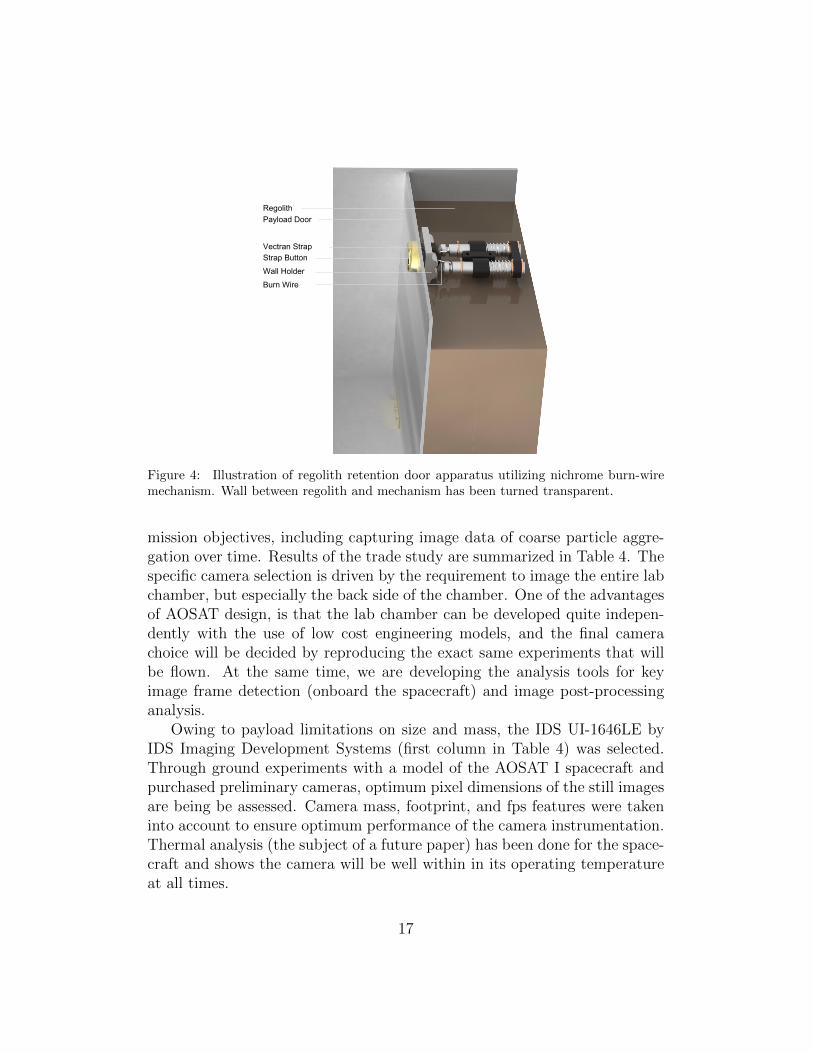
Vectran StrapStrap Button
Payload Door
Wall Holder
Burn Wire
Regolith
Figure 4: Illustration of regolith retention door apparatus utilizing nichrome burn-wiremechanism. Wall between regolith and mechanism has been turned transparent.
mission objectives, including capturing image data of coarse particle aggre-gation over time. Results of the trade study are summarized in Table 4. Thespecific camera selection is driven by the requirement to image the entire labchamber, but especially the back side of the chamber. One of the advantagesof AOSAT design, is that the lab chamber can be developed quite indepen-dently with the use of low cost engineering models, and the final camerachoice will be decided by reproducing the exact same experiments that willbe flown. At the same time, we are developing the analysis tools for keyimage frame detection (onboard the spacecraft) and image post-processinganalysis.
Owing to payload limitations on size and mass, the IDS UI-1646LE byIDS Imaging Development Systems (first column in Table 4) was selected.Through ground experiments with a model of the AOSAT I spacecraft andpurchased preliminary cameras, optimum pixel dimensions of the still imagesare being be assessed. Camera mass, footprint, and fps features were takeninto account to ensure optimum performance of the camera instrumentation.Thermal analysis (the subject of a future paper) has been done for the space-craft and shows the camera will be well within in its operating temperatureat all times.
17

Table 4: Detailed camera trade study
Camera IDS UI-1646LE
NanoCamC1U 3 MB
KodakMCM20027
HTC Evo& LGOptimus
µCAMTTL Om-nivision
Pixels(MP)
1.3 3 1.3 1.3 0.3
Pixel Dim. 1280 ×1024
2048 ×1536
1280 × 1024 1280 × 1024 640 × 480
CaptureRate (fps)
25 20 10 30 30
Technology CMOS CMOS CMOS CMOS CMOSInterface USB 2.0 I2C I2C N/A TTLMass (g) 12 166 20 < 10 6FlightHeritage
MCUBED,MichiganU.
multiple AAUSAT,Alborg U.
N/A multiple
Footprint(cm)
3.6×3.6×1.0 9.6×9.0×5.8 2.4×2.4×1.0 3.6×3.6×1.0 3.2×3.2×2.1
18

Figure 5: Illustration of final three camera design incorporating a single fixed camera andtwo cameras affixed to a rotating plate.
3.3.4. Attitude Determination and Control
Maintaining attitude control of AOSAT I is a critical requirement dur-ing the centrifuge experiments. For instance, the shifting regolith within theexperimental chamber of the spacecraft results in a dynamic center of mass,potentially causing nutations of the satellite. During the centrifuge experi-ments, the spacecraft will be spinning at 1 rpm with respect to its primaryaxis. Following the conventions of orienting body and orbit frames, this rota-tion axis will be the body x-axis for AOSAT I, and the rotation angle (Eulerangle) will be referred to as roll.
AOSAT I will employ an onboard inertial measurement unit (IMU) whichconsists of a 3-axis accelerometer in addition to the onboard BMA250. Un-fortunately the BMA250 cannot sense the required 1 rpm and hence we areusing a second accelerometer that can operate in ranges varying from ±1 gto ±16 g; a gyro (L3G4200D) with operating range from 250◦/s to 2000◦/s,and a 3-axis magnetometer (HMC5883L) which operates within a full scalerange of ±8 G. These sensors can be tuned for various operating ranges,sensitivities and sampling periods. A similar IMU (GY-80 from ShenzhenGuangshun Electronics), which has the same gyro and magnetometer but adifferent accelerometer (ADXL345), is presently being used for in-laboratorytesting, as a substitute for the on-board IMU. All the sensors are being col-lectively sampled at a rate of 100 Hz with the following settings:
• accelerometer range of ±16 g and a sensitivity of 0.03125 mg/LSB
19
• gyro range of 500◦/s and a sensitivity of 17.5 mdeg/s/LSB
• magnetometer range of ±1.3 G and a sensitivity of 0.92 mG/LSB
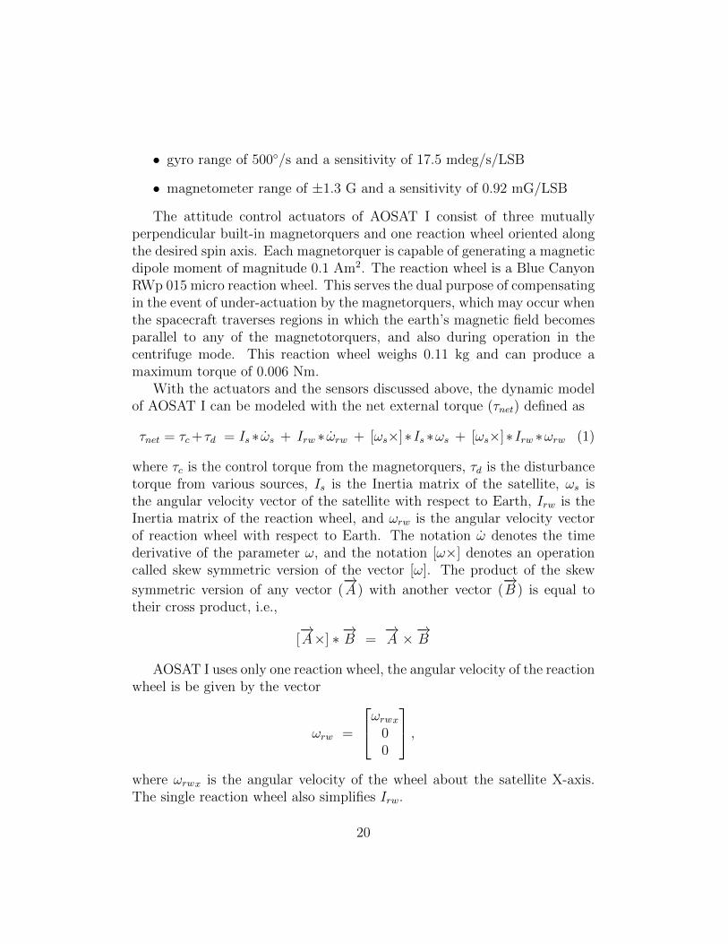
The attitude control actuators of AOSAT I consist of three mutuallyperpendicular built-in magnetorquers and one reaction wheel oriented alongthe desired spin axis. Each magnetorquer is capable of generating a magneticdipole moment of magnitude 0.1 Am2. The reaction wheel is a Blue CanyonRWp 015 micro reaction wheel. This serves the dual purpose of compensatingin the event of under-actuation by the magnetorquers, which may occur whenthe spacecraft traverses regions in which the earth’s magnetic field becomesparallel to any of the magnetotorquers, and also during operation in thecentrifuge mode. This reaction wheel weighs 0.11 kg and can produce amaximum torque of 0.006 Nm.
With the actuators and the sensors discussed above, the dynamic modelof AOSAT I can be modeled with the net external torque (τnet) defined as
τnet = τc+τd = Is ∗ ωs + Irw ∗ ωrw + [ωs×]∗Is ∗ωs + [ωs×]∗Irw ∗ωrw (1)
where τc is the control torque from the magnetorquers, τd is the disturbancetorque from various sources, Is is the Inertia matrix of the satellite, ωs isthe angular velocity vector of the satellite with respect to Earth, Irw is theInertia matrix of the reaction wheel, and ωrw is the angular velocity vectorof reaction wheel with respect to Earth. The notation ω denotes the timederivative of the parameter ω, and the notation [ω×] denotes an operationcalled skew symmetric version of the vector [ω]. The product of the skew
symmetric version of any vector (−→A ) with another vector (
−→B ) is equal to
their cross product, i.e.,
[−→A×] ∗
−→B =
−→A ×
−→B
AOSAT I uses only one reaction wheel, the angular velocity of the reactionwheel is be given by the vector
ωrw =
ωrwx00
,where ωrwx is the angular velocity of the wheel about the satellite X-axis.The single reaction wheel also simplifies Irw.
20

Rearranging Equation 1, yields the nonlinear dynamic model for AOSATI:
ωs = −Is−1∗ (Irw∗ωrw + [ωs×]∗Is∗ωs + [ωs×]∗Irw∗ωrw ) + τd + τc. (2)
Equation 2 illustrates the relationship between the desired state (ωs),and the control terms (ωrw, and τc) under external forcing, in the form x =f(x, U). A linear control law of the form U = Kx was used for simulatingthe model, and to test control response.
(a) Test-1
(b) Test-2
Figure 6: Attitude control on Roll axis for test conditions summarized in Table 5.
Figure 6 shows the attitude response of two simulations that were runwith different conditions (summarized in Table 5). The results suggest that,with the proposed controller, the model is robust to disturbance torques ofmagnitude 3.4 × 10⁻⁷ Nm caused by gravity and solar radiation pressure.
21

Table 5: Simulation Results
Parameter Test 1 Test2Initial conditions (rad/sec) ωx = 0.01 ωx = 0.01
ωy = 0.01 ωy = −0.01ωz = 0.01 ωz = −0.01
Final conditions (rad/sec) ωx = 0.1 ωx = 0.1ωy = 0 ωy = 0ωz = 0 ωz = 0
Disturbance torque (Nm) 3.4× 10⁻⁷ 3.4× 10⁻⁷
Settling time (sec) 575 575Reaction wheel acceleration (rad/s2) 25 25Magneto-torquer Current (A) 3 3Energy Consumption (Whr) 2 2
Figures 6a and 6b show that the roll rate of the satellite settles to 0.1 rad/s(≈ 1 rpm), in less than 600 s with a pointing accuracy of 2◦. This controllerrequired 2 Whr of power with an error of 0.3 rpm. It is possible to furtherreduce the settling time by providing additional power. For instance, anadditional 1.5 Whr resulted in a settling time of 300 s.
3.3.5. Power
The AOSAT I power system architecture relies on the electrical power sys-tem capabilities integrated with the Tyvak flight computer and supplementedby a 3.7 V lithium-ion battery pack, storing 37 Whr of energy. Modeling ofsystem energy consumption indicates that AOSAT I lies within power bud-get margin for both sun-synchronous and ISS deployment orbits. The powerbudget is summarized in Table 6. Calculations based on peak optimal dutycycles for spacecraft subsystems and payload instrumentation yield an energyconsumption rate of ∼ 80 Whr/day. The International Space Station deploy-ment orbit produces nearly 100 Whr/day, which gives a 17% power margin,while sun-synchronous orbit yields 190 Whr/day and so there is excess power.Duty cycles for this calculation assume peak onboard data processing, scien-tific operation and radio communication throughout the course of a standardoperational day. Basic spacecraft functionality consumes 33 Whr/day, leav-ing sufficient energy for scientific operations with either orbit.
22

Table 6: Itemized AOSAT I Daily Power Budget
Subsystem Duty Cycle Unit Power (W) Energy (Whr)C&DH 1.0 Intrepid System 0.1 2.9Comm. 0.1 UHF 1.5 3.6
0.1 S-Band 10 24ADCS 0.5 Reaction Wheel 2 24
1.0 Magnetorquer 0.1 2.4Science 0.2 Cameras 0.8 3.6
0.04 Piezo 0.1 0.10.2 LED Array 2.9 14
Data 0.6 Intrepid System 0.5 7.2Total Energy Consumed Per Day 80Energy Generated Per Day (ISS) 96
Energy Margin Per Day (ISS) 17%Energy Generated Per Day (Sun-Sync) 190
3.4. Communications
Determination of an effective communications system required detailedanalysis of the prospective spacecraft orbits and ground station coverage. Us-ing AGI’s System’s Tool Kit (STK) software, the requested Sun-synchronousorbit of 450 km × 810 km at 97.2◦ inclination was propagated in order togenerate coverage estimates. Coverage modeling required propagation ofAOSAT I’s estimated location and altitude during the first 30 days after de-ployment on the proposed trajectory. Appendix A includes details on the linkbudget calculations and this includes link budget for UHF, Figure A.13 andS-band, Figure A.14. The calculations are respect to the elevation angles (0◦
to 90◦). The primary location for AOSAT I ground station communicationwill be Arizona State University (ASU), although other locations have beenconsidered.
The coverage analysis for ASU’s location yielded a minimum access timeof 113 s (2.88 min.), a maximum access time of 928 s (15.5 min.) and a meanaccess time of 633 s (11 min.). The orbit results in approximately 5 passesevery 24 hrs, averaging approximately 52 min. per day to downlink data.Utilizing ASU as the only ground station would restrict daily communicationto 3.0-3.8% of the orbit, corresponding to approximately 13-16 MB per dayusing a 38400 bps data rate and about 38-48 MB per day using a 115200 bps
23

data rate.Incorporating partner ground stations would increase coverage and pro-
vide higher data throughput. Table 7 shows an average time (in seconds) theAOSAT I will be above 0◦ elevation angle with respect to various points onearth.
Table 7: Approximate access times(in seconds) for 4 earth locations over 30 days
Obit Type ASU Seattle FairbanksNew
Zealand
Sun-Sync 100,000 140,000 250,000 85,000ISS 100,000 100,000 45,00 120,000
AOSAT I will have two communications systems including a UHF and S-band. The primary communication system is the UHF transmitter/receiverprovided by Tyvak. This board is easily integrated with the Tyvak hardwareand software suite, making it a reliable primary communication system. TheUHF platform communicates via a deployable L-dipole antenna, integratedinto the Tyvak hardware suite. UHF data transmission will consist of down-linking spacecraft operating parameters and uplinking commands for payloadexperiments. The secondary communication system will handle downlinkingexperimental data and telemetry.The s-band transmitter is Quasonix nan-oTX, which supports frequencies between 1.4-2.2 GHz and is in a small formfactor(20.89 cm3), and has a proven track record alongside the Tyvak IntrepidSystem Board.
3.4.1. Command and Data Handling
The Tyvak Intrepid System Board (shown in Figure 7) acts as the com-mand and data handling controller onboard AOSAT I. The Intrepid platform,produced by Tyvak Nano-Satellite system Inc., provides an integrated com-mand and data handling architecture, as well as an electrical power system,in a CubeSat form factor. This model is CDS compliant with and meetsall required specifications relevant to the Poly Picosatellite Orbital Deployer(P-POD). Intrepid is specifically designed with terrestrial development inmind with the end objective of small, lightweight spacecraft. The systemboard comes with an umbilical development board that handles debugging,terminal I/O, power and efficient board access even while integrated into thefinal mission form factor. Tyvak Intrepid has a flight legacy with 3 CubeSats
24

currently in orbit from the TLS-01 mission and is a system board for NASAsINSPIRE interplanetary CubeSat.
Figure 7: Tyvak Intrepid System Board.
Intrepid, comprised of a main system board and additional breakout util-ity specific boards, will act as a centralized computational center for all data,communications and spacecraft specific command handling. Data is handledvia SPI, USB, UART and I2C busses and stored in an SQLite database andintegrated high capacity MicroSD card. Intrepid provides multiple bus solu-tions under each interface to streamline the separation of spacecraft avionicscommands from payload specific operations.
3.4.2. Data Processing
Owing to the limitations of AOSAT I communications bandwidth andour need to quantify particle motion, it is critical to develop an algorithm toidentify, track, record, and transmit the evolution of suspended particles tothe communications ground station. Our technique utilizes algorithms thatexploit particle reflectivity and shadowing in order to identify and track theparticles of interest. This will enable us to place LED lights at an optimallocation within the CubeSat, thus allowing the camera system to aid in theparticle detection process. Our studies show a minimum of a 50-fold savingsin data bandwidth for tracking and detection of dust particles compared toconventional, non-lossy compression image capture.
Our particle tracking technique utilizes algorithms written in Matlab andtested in ground experiments that will exploit particle evolution and motion
25

over time in order to identify and track the particles of interest. The utiliza-tion of both Lucas-Kanade [35] and Horn-Schunck [36] optical flow estimationmethods are key in accounting for displacements of particle groupings on arange of scales. For every pixel in the region of interest, a motion vector iscalculated in both the x and y directions. This allows mapping of one pixelthrough a series of frames. The particle optical flow code assigns a movementvector (u,v) to every interesting pixel, yielding a flow field, both true colorand colorized. Sequences of images captured over time will be processedand analyzed for noise, motion, shadowing, and particle statistics, aiding inconstraining the parameters of the code and data analysis.
Use of multiple cameras allows for depth of field to be calculated andprocessed. This data is significant for early verification of expected aggregatedistribution with respect to the spacecraft center of mass, as well as to meetscientific objectives pertaining to particle accretion. In similar equidistantintervals to the particle tracking frames, the Tyvak Intrepid will take stereoimage pairs to determine current particle distribution inside the experimentalchamber. This process is illustrated in Figure 8.
Command-driven software protocols allow for the downlink of individualframes, index ranges, or complete experimental data sets. These commands,transmitted to the spacecraft via UHF, initiate the transfer of images speci-fied from the database to the downlink queue, stored on the MicroSD memorycard. Once the command has been received, the Tyvak Intrepid processesthe command data and transfers the requested section of scientific data fromthe storage database to the downlink queue. Scientific data is prioritized last,behind spacecraft telemetry data and initial experimental keyframe sciencedownlinks, as these are needed to maintain ongoing spacecraft operationsand plan future experiments, respectively.
The mission profile includes three phases of science operation (Table 8).The first phase of operation begins with door actuation, releasing the me-teorite aggregate into the science chamber. The door deployment will bephotographed in stereo for 30 seconds at 25 frames per second (the operat-ing limitation of the camera), followed by stereo images being recorded for10 minutes at 1 frame per second. The second mission phase includes threemicrogravity experiments to monitor meteorite particle aggregation over dif-ferent periods of time ranging from four to fifteen hours, with data beingcollected in stereo at a maximum frame rate of 6 frames per minute. Thefinal mission phase will consist of eleven experiments, utilizing the centrifugecapability of the spacecraft to produce varying gravity fields to monitor pack-
26

Figure 8: Graphical depiction of data handling procedures.
ing of asteroid Regolith. Impact dynamics will be monitoring during startingand stopping of the centrifuge capability. Experiments will last one hour anddata will be recorded in stereo at 15 frames per minute. In each of thesephases, a certain number of key frames will be recorded. Key frames aremeant to convey the state of the experiment at a glance. For the door de-ployment phase, there will be 340 key frames. The total number of framesgenerated will be 1350 frames over the duration of door opening sequence.Key frames are interspersed during each experiment or phase and are nottaken at regular time intervals. A key frame is made by monitoring theShannon’s entropy of particle spatial distribution in the experimental area[37, 38]. This algorithm will be used to determine the Shannon’s entropyof the particles in the experiment chamber volume. When particles aggre-
27

gate, the Shannon’s entropy decreases and it increases if the particles aredispersed. A major change in Shannon’s entropy is of interest to us and isused to trigger recording a key frame. Afterwards, the changes in Shannon’sentropy is ranked and the top 340 is downloaded for the door opening se-quence. A lot more key frames are generated for the door open sequence tohelp validate the key frame generating algorithm before the science experi-ments start. Out of the 1010 frames generated, twenty two percent of thenon-key frames will be downloaded and is 225 frames. For the microgravityexperiments, 100 key frames will be generated over the 3 experiments. Fur-thermore 3,333 non-key frames will be generated for each experiment andequally timed over the length of the experiment.
For the impact dynamics and centrifuge experiments, 275 key frameswill be generated over the 11 individual experiments. Therefore the totalnumber of frames downloaded is the sum of the key frames and total framesproduced multiplied by the fraction to be downloaded. The total number offrames downloaded from all three missions phases is 4,390 frames and eachstereo pair of images is presumed to be 300 Kb. The total amount of datato be downloaded is 1.5 GB and includes 0.18 GB science data margin.
4. Feasibility Experiments
The behavior of regolith and rocks in low gravity is important to theunderstanding of primary accretion, asteroid surface properties, and for haz-ardous asteroid mitigation work. In order to better understand how regolithand rocks behave in low gravity, we have developed the Astrophysical Rub-ble piles Simulation Software (ARSS), utilized ground experiments testingneutrally buoyant beads and water in an experimental cubesat, and imagedparticle-shake tests in order to test the particle tracking method with varyinggrain sizes.
4.1. Particle Simulations
Particle simulations support mission operations in developing models ofanticipated interactions of regolith particles and in planning for guidancenavigation and control scenarios. Understanding the physical interactions ofparticles under different gravity conditions allows for better understandingof settling time during different experimental phases of the mission. Thisinformation allows for better mission planning for both scientific results andengineering spacecraft stability. Bead deployment from the nitrogen blower
28

Table 8: Theoretical data volume for primary mission
Experim.Phase
# ofExp.
# KeyFrames
NonKeyFramesProd.
Fractiond/l
Framesd/l
DoorDeploy.
1 340 1010 0.22 565
MicrogravityExperim.
3 100 10000 0.25 2600
ImpactDynamics&Centrifuge
11 275 9625 0.13 1225
Data Per Frame 300 KbTotal Mission Frames 4,390Margin 0.18
GbTotal Mission Data 1.5 Gb
29

and the initiation of the centrifuge both contain relatively large uncertaintiesas these experiments cannot be accurately modeled under the conditionsof terrestrial gravity. To reduce uncertainty related to particle interactionsduring these events, relevant parameters were modeled to best calibrate thescientific instruments and spacecraft stability system.
Particle interactions were modeled with the PhysX physics engine as partof the Nividia CUDA development environment. Utilizing graphical process-ing units (GPUs), models of a collisional environment can be generated inorder to investigate the effect of differing values of parameters such as gravity,particle density, elasticity, and particle density.
Such simulations were conducted, defining parameters to model the op-erating environment of the payload chamber in low gravity conditions withparticles similar to the meteorite regolith contained in the AOSAT I sciencepayload. These simulations were comprised of 33, 000 individual particleswith a diameter of 0.313 mm inside a 2 cm3 domain. The simulation domainconsists of 643 grid spaces in each direction, with each cell consistent withthe diameter of a particle. Uniform grid subdivision is utilized to determineparticle to particle interactions. This bound limits the number of particles inthree-dimensional space which can inhabit any one grid cell to 4. Addition-ally, the number of cells a single particle inhabits at any given instant is alsoconstrained to 8. The center location of the particle determines its primarycell which is then utilized to determine relevant particle interactions with allinhabiting particles.
Initiation of centrifugation generates significant uncertainty in the centerof mass of the laboratory-spacecraft, and consequently there are issues wehave had to address concerning the guidance and control of AOSAT I. Mod-eling the particle interactions with varying centripetal accelerations allowsfor further insight into particle settling time, and thus, further terrestrialrefinement of the AOSAT I attitude control algorithms. A series of particlesimulations were undertaken with varying magnitudes of artificial gravita-tional acceleration in order to investigate the dynamics of the regolith slosh-ing within the science chamber due to the spacecraft rotation. Results areshown in the sequential images of Figure 9, illustrating the distribution ofparticles at various times (as noted in each panel) corresponding to gravita-tional accelerations of 0.01 g (Fig. 9a), 0.001 g (Fig. 9b), and 0.0001 g (Fig.9c).
The longest particle settling time observed was 75 s under an accelerationof 0.0001 g. In all scenarios, the majority of the regolith transferred to the
30

aft of the science chamber within 20 s of centrifugation. This mass distri-bution is comparable to the launch configuration with the particles packedin the area below the door. The rate of spin-up for the centrifuge must becalibrated against data inferred from the particle simulation data to reducesignificant perturbations produced by particles packing with too large of aninitial velocity. Conversely, a spin-up that is too slow will result in a lengthysettling time. While a lengthy settling time does not interfere with scienceobjectives, it is important to know the settling time so that we can knowwhen and for how long to turn on the cameras for data acquisition.
(a) 0.01 g
(b) 0.001 g
(c) 0.0001 g
Figure 9: Time sequence of particle settling dynamics under gravitational accelerationsof 0.01 g (top panel), 0.001g (middle panel), and 0.0001g (bottom panel).
4.2. Particle Dynamics Using CubeSat Centrifuge Model
For the proposed AOSAT I experiment, we developed an analogue to bet-ter understand particle behavior in a rotating centrifuge. This analogue isnot meant to test the physics but to help conceptualize the experiment and
31
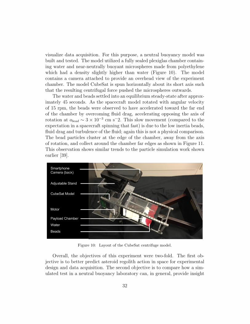
visualize data acquisition. For this purpose, a neutral buoyancy model wasbuilt and tested. The model utilized a fully sealed plexiglas chamber contain-ing water and near-neutrally buoyant microspheres made from polyethylenewhich had a density slightly higher than water (Figure 10). The modelcontains a camera attached to provide an overhead view of the experimentchamber. The model CubeSat is spun horizontally about its short axis suchthat the resulting centrifugal force pushed the microspheres outwards.
The water and beads settled into an equilibrium steady-state after approx-imately 45 seconds. As the spacecraft model rotated with angular velocityof 15 rpm, the beads were observed to have accelerated toward the far endof the chamber by overcoming fluid drag, accelerating opposing the axis ofrotation at abead ∼ 3× 10⁻³ cm s−2. This slow movement (compared to theexpectation in a spacecraft spinning that fast) is due to the low inertia beads,fluid drag and turbulence of the fluid; again this is not a physical comparison.The bead particles cluster at the edge of the chamber, away from the axisof rotation, and collect around the chamber far edges as shown in Figure 11.This observation shows similar trends to the particle simulation work shownearlier [39].
Figure 10: Layout of the CubeSat centrifuge model.
Overall, the objectives of this experiment were two-fold. The first ob-jective is to better predict asteroid regolith action in space for experimentaldesign and data acquisition. The second objective is to compare how a sim-ulated test in a neutral buoyancy laboratory can, in general, provide insight
32

into milligravity centrifuge experiments. For instance, on the basis of thesestudies we expect that the regolith particles inside AOSAT-I will not all set-tle at the far wall of the chamber. Instead we might anticipate that mostwill cluster initially at the far edge, and a certain portion will accumulate atthe corners, prior to using the vibrator to flatten and disperse the regolithbed.
Figure 11: The right side of the chamber is closest to the spin axis. As the chamber isspun at a rate of 15 rpm, the particles start to migrate and deposit towards the outeredges. This evolution of particle position is shown at time =0, 3 seconds, 7 seconds, 17seconds, 21 seconds and 27 seconds.
5. Discussion
In this work we demonstrate the preliminary feasibility of a CubeSat cen-trifuge to perform simulation of asteroid surfaces. The spacecraft, when notspinning, will be used to conduct regolith aggregation experiments. Throughour design process, we have identified off the shelf components including theTyvak CubeSat bus, S-band communication system, Blue Canyon ReactionWheel and solar panels embedded with magneto-torquers. Using these com-ponents, we can simplify the design and development of the proposed labora-tory. A science payload will be developed in-house and be instrumented with3 cameras, contain a packaging system for carrying the regolith into spaceand will have a bead deployment instrument, that will release bead into asimulated asteroid surface formed from the regolith settling at the edge ofthe chamber when the spacecraft is spinning.
We considered multiple designs including an asymmetrical two chamberdesign, a two chamber symmetrical design and a single chamber design. Asingle chamber design offers low development risk and is overall simpler toimplement with sufficient volume margins for the science instruments. Thekey determining factor is that the payload chamber be large enough to permitobservation of the regolith while reducing concerns of occlusion and wall/edgeeffects. A single chamber design however requires more power be expendedin lighting the chamber.
33

In our proposed system, we will use the magnetorquers to hold the Cube-Sat pinned to the Earth’s magnetic field lines and then use the reaction wheelto spin it about the minor axis. Through this work, we demonstrate that itis feasible and that we have enough control authority to prevent unwantedtumbles, and sufficiently rapid settling time.
Overall, the system is feasible, with a mass margin of 23%, volume mar-gin of 60% and 45% energy margins when deployed on a sun-synchronousorbit. On an ISS orbit, there is a negative energy margin and this wouldrequire delaying certain science experiments and thus stretching out the pri-mary mission. Overall, both ISS and sun-synchronous orbits are viable forthe proposed concept. Software simulation of regolith particles show thefeasibility of simulating low-gravity particle interactions. Further work wasdone using a model of a CubeSat to demonstrate the centrifuge effect. Plas-tic beads in water simulated the low gravity conditions. The results supportobservations that most of the regolith will settle at the furthest wall edges,but some of the regolith will cling and settle at the payload chamber walls.
For the proposed mission, utilizing only the UHF antenna and our mainground station for communication poses significant challenges in communi-cating the primary science data over a 1 month period. Our studies showthat data reduction methods can be used to transmit the highest priorityscience data using UHF alone. However this is insufficient for transmittingvideo. The situation improves if we network our ground station with others toincrease daily coverage. The situation further improves if an S-band commu-nication were to be used. Overall, our studies shows a promising developmentpathway for the assembly and testing of the AOSAT I CubeSat mission fordemonstration of the two major mission objectives, namely to demonstrateregolith aggregation in space and for demonstrating a centrifuge laboratoryin microgravity.
6. Conclusions
In this paper we propose development of AOSAT I, an on-orbit, 3U (34 ×10 × 10 cm), 4 kg CubeSat centrifuge, designed to simulate asteroid surfaceconditions. Demonstration of this CubeSat will provide a low-cost pathwayto physical asteroid model validation, shed light on the origin of asteroids,and constrain the design of future landers, rovers, and resource extractors.AOSAT I will house crushed meteorites (remnants of asteroids) and enablescientific experiments within its payload chamber while operating in two dis-
34

tinct modes: 1) a centrifuge producing artificial gravity to simulate surfaceconditions on asteroids of diameter up to 20 km, and 2) as a stationary micro-gravity laboratory to investigate primary accretion. Analysis of the feasibilityof this proposed spacecraft shows healthy mass, volume and energy marginsfor a sun synchronous orbit. The system will be built mostly of off-the-shelfcomponents, except for the payload chamber, consisting of custom camera,a regolith container and bead deployer that will interact with regolith. Sim-ulation of the proposed attitude control system shows that spacecraft canspin between 0 to 4 rpm to produce the required centrifugal force, withoutrisk of tumbling. The proposed system illustrates the effective use of low-cost, off-the-shelf components in the rapid assembly and instrumentation ofa CubeSat science laboratory. Successful demonstration of this science labo-ratory can open the pathway to more ambitious missions to simulate a widerrange of ‘gravity’, from the smallest asteroid to the Moon and larger bodies,for applications in life-sciences, materials testing, manufacturing, planetarygeology, and 3D printing in space.
Appendix A. Link Budget
This following section shows calculation of the link budget for the AOSAT1 spacecraft. Figure A.12 shows the position of the spacecraft relative to theground station and Figure A.13 shows detailed Uplink and Downlink budgetfor UHF communication. Figure A.14 shows detailed Uplink and Downlinkbudget for S-band communication.
Boltzmann Constant: kB = −228.6 dBWHz∗K
Speed of Light: C = 299792458 msec
Mean Radius of Earth: kE = 6378140 metersMean Orbit Radius of AOSat: kA = kE + Perigee+Apogee
2= 6378770 meters
Mean Orbit Radius of Globalstar: kG = kE + 1414 = 6379554metersElevation angle: δ1 or δ2 = (variable) degreesFrequency: f = (variable) HzData Rate: RD = (variable) bpsTransmit Power: PTX =(variable) WattsData Bandwidth relative to one Hertz: RdBW = 10 ∗ log10(RD)dBHzFrequency Wavelength: λ = C
fmeters
Slant Range for ground station:S1 = kE ∗ [
√k2A/k
2E − cos2(Π ∗ δ1/180)− sin(Π ∗ δ1/180)]
Slant Range for Globalstar satellite:
35
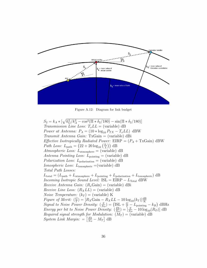
Figure A.12: Diagram for link budget
S2 = kA ∗ [√k2G/k
2A − cos2(Π ∗ δ2/180)− sin(Π ∗ δ2/180)]
Transmission Line Loss: TxLL = (variable) dBPower at Antenna: PA = (10 ∗ log10 PTX − TxLL) dBWTransmit Antenna Gain: TxGain = (variable) dBiEffective Isotropically Radiated Power: EIRP = (PA + TxGain) dBWPath Loss: Lpath =
(22 + 20 log10
(Si
λ
))dB
Atmospheric Loss: Latmosphere = (variable) dBAntenna Pointing Loss: Lpointing = (variable) dBPolarization Loss: Lpolarization = (variable) dBIonospheric Loss: Lionospheric =(variable) dBTotal Path Losses:Ltotal = (Lpath + Latmosphere + Lpointing + Lpolarization + Lionospheric) dBIncoming Isotropic Sound Level: ISL = EIRP− LTotal dBWReceive Antenna Gain: (RxGain) = (variable) dBiReceive Line Loss: (RXLL) = (variable) dBNoise Temperature: (kT ) = (variable) KFigure of Merit: (G
T) = [RXGain−RXLL− 10 log10(kT )]dB
K
Signal to Noise Power Density: ( SNo
) =(ISL + G
T− Lpointing − kB
)dBHz
Energy per bit to Noise Power Density: ( EbNo
) = [ SNo− 10 log10(RD)] dB
Required signal strength for Modulation: (MT ) = (variable) dBSystem Link Margin: =
[EbNo−MT
]dB
36

Figure A.13: Uplink and Downlink budgets for UHF using typical parameters
[1] N. R. C. of the National Academies, Vision and Voyages for PlanetaryScience in the Decade 2013-2022, The National Academies Press, Wash-ington, D.C., 2011.
[2] H. Yano, T. Kubota, H. Miyamoto, T. Okada, D. Scheeres, Y. Tak-agi, K. Yoshida, M. Abe, S. Abe, O. Barnouin-Jha, A. Fujiwara,S. Hasegawa, T. Hashimoto, M. Ishiguro, M. Kato, J. Kawaguchi,T. Mukai, J. Saito, S. Sasaki, M. Yoshikawa, Touchdown of the HayabusaSpacecraft at the Muses Sea on Itokawa, Science 312 (2006) 1350–1353.
[3] E. Hand, Philae probe makes bumpy touchdown on a comet, Science346 (2014) 900–901.
[4] R. Z. Sagdeev, A. V. Zakharov, Brief history of the Phobos mission,Nature 341 (1989) 581–585.
[5] L. R. Nittler, Near-Shoemaker at Eros: The first detailed explorationof an asteroid, Elements 10 (2014) 51–52.
[6] T. Saiki, H. Sawada, C. Okamoto, H. Yano, Y. Takagi, Y. Akahoshi,
37

Figure A.14: Uplink and Downlink budgets for S-Band using typical parameters
M. Yoshikawa, Small carry-on impactor of Hayabusa2 mission, ActaAstronautica 84 (2013) 227–236.
[7] C. Lange, C. Dietze, T.-M. Ho, O. Kroemer, M. Lange, S. Wagenbach,L. Witte, The MASCOT-Study Team, Baseline Design of a MobileAsteroid Surface Scout (MASCOT) for the Hayabusa 2 Mission.
[8] T. Yoshimitsu, T. Kubota, A. Tomiki, MINERVA-II rovers developedfor Hayabusa-2 mission, in: Low Cost Planetary Missions Conference-11, June, 2015.
[9] K. Ennico, D. Durda, Box of Rocks: An experiment to study the evolu-tion of regolith blocks in microgravity, in: Next-Generation SuborbitalResearchers Conference, 2011.
[10] F. J. Haddy, NASA has its biological groundwork for a trip to Marsimproved?, The FASEB Journal 21 (2007) 643–646.
[11] T. Taylor, Centrifugal gravity habitation torus constructed of salvagedorbital debris, 2001. US Patent 6,206,328.
38

[12] G. H. Fichtl, R. L. Holland, Simplified model of statistically station-ary spacecraft rotation and associated induced gravity environments,NASA-TM-78164, 1978.
[13] E. Asphaug, J. Thangavelautham, Asteroid Regolith Mechanics andPrimary Accretion Experiments in a Cubesat, in: Proceedings of the45th Lunar and Planetary Science Conference, Houston, Texas, March,2014, Paper 2306.
[14] J. Thangavelautham, A. Thoesen, F. Gadau, G. Hutchins, E. Asphaug,I. Alizadeh, Low-Cost Science Laboratory in Microgravity Using a Cube-Sat Centrifuge Framework, in: Proceedings of the 65th InternationalAstronautical Congress, Toronto, 2014.
[15] A. Johansen, E. Jacquet, J. N. Cuzzi, A. Morbidelli, M. Gounelle, NewParadigms For Asteroid Formation, in: Asteroids IV, University ofArizona Press, 2015, pp. 471–492.
[16] J. Brisset, D. Heißelmann, S. Kothe, R. Weidling, J. Blum, The Subor-bital Particle Aggregation and Collision Experiment (SPACE): Studyingthe collision behavior of submillimeter-sized dust aggregates on the sub-orbital rocket flight REXUS 12, Review of Scientific Instruments 84(2013) 094501.
[17] S. G. Love, D. R. Pettit, S. R. Messenger, Particle aggregation in mi-crogravity: Informal experiments on the International Space Station,Meteoritics & Planetary Science 49 (2014) 732–739.
[18] J. R. Marshall, T. B. Sauke, J. N. Cuzzi, Microgravity studies of ag-gregation in particulate clouds, Geophysical Research Letters 32 (2005)11202.
[19] G. Praburam, J. Goree, Cosmic dust synthesis by accretion and coagu-lation, Astrophysical Journal 441 (1995) 830–838.
[20] H. Chennaoui-Aoudjehane, A. Jambon, M. Bourot Denise,O. Boudouma, J. Gattacceca, P. Weber, P. Bonte, TamdakhtMeteorite: The last Moroccan fall, Meteoritics and Planetary ScienceSupplement 72 (2009) 5038.
39

[21] K. E. Tsiolkovsky, Grezy O Zemle I Nebe [i] Na Vests (Speculations ofEarth and Sky, and On Vesta, science fiction works), Izd-vo AN SSR,1895.
[22] T. W. Hall, The Architecture of Artificial-Gravity Environments forLong-Duration Space Habitation (University Microfilms 9423117), Doc-toral dissertation, University of Michigan, 1994.
[23] K. Gatland, Manned Spacecraft, MacMillan Publishing Co., Inc., secondedition, 1976.
[24] K. Kumar, Review on dynamics and control of nonelectrodynamic teth-ered satellite systems, Journal of Spacecraft and Rockets 43 (2006)705–720.
[25] M. P. Cartmell, D. J. McKenzie, A review of space tether research,Progress in Aerospace Sciences 44 (2008) 1–21.
[26] A. K. Misra, Dynamics and control of tethered satellite systems, ActaAstronautica 63 (2008) 1169–1177.
[27] Z. Cai, X. Li, H. Zhou, Nonlinear dynamics of a rotating triangulartethered satellite formation near libration points, Aerospace Scienceand Technology 42 (2015) 384 – 391.
[28] B. Wong, A. Misra, Planar dynamics of variable length multi-tetheredspacecraft near collinear Lagrangian points, Acta Astronautica 63 (2008)1178–1187.
[29] B. Dalton, K. Plaut, G. Meeker, Life sciences research in the CentrifugeAccommodation Module of the International Space Station, TechnicalReport 2000-01-2247, SAE, 2000.
[30] H. Gindl, J. Scheimann, M. Shirakawa, V. Suvorov, J. Uri, Research onInternational Space Station - Building a Partnership for the Future, in:55th International Astronautical Congress, Vancouver, 2004.
[31] M. Holderman, E. Henderson, Nautilus-X multi-mission space explo-ration vehicle, Future in Space Operations (FISO) Colloquium, 2011.
[32] J. Z. Kiss, Plant biology in reduced gravity on the Moon and Mars,Plant Biology 16 (2014) 12–17.
40

[33] D. Cotto-Figueroa, E. Asphaug, L. A. J. Garvie, A. Rai, J. John-ston, L. Borkowski, S. Datta, A. Chattopadhyay, M. A. Morris, Scale-dependent measurements of meteorite strength: Implications for aster-oid fragmentation, Icarus 277 (2016) 73–77.
[34] CubeSat Design Specification (CDS) - Rev. 13, April, 2015.
[35] B. D. Lucas, T. Kanade, An Iterative Image Registration Techniquewith an Application to Stereo Vision (DARPA), in: Proceedings of the1981 DARPA Image Understanding Workshop, 1981, pp. 121–130.
[36] B. K. Horn, B. G. Schunck, Determining optical flow, Artificial Intelli-gence 17 (1981) 185–203.
[37] J. Thangavelautham, T. Barfoot, G. D’Eleuterio, Coevolving Commu-nication and Cooperation for Lattice Formation Tasks (Updated), in:Advances In Artificial Life: Proc. of the 7th European Conference onALife (ECAL), Springer-Verlag, 2003, pp. 857–864.
[38] J. Thangavelautham, T. Barfoot, G. D’Eleuterio, Evolutionary-BasedControl Approaches for Multirobot Systems, in: Frontiers in Evolution-ary Robotics, Intech, 2008, pp. 35–60.
[39] V. Perera, N. Movshovitz, E. Asphaug, J. Thangavelautham, MaterialStudies of Asteroid Regolith and Accretion Using a Low-Cost CubeSatLaboratory, in: Proceedings of the 65th International AstronauticalCongress, Toronto, 2014.
41