ASSOCIATED LAUNCHING EQUIPMENT - · PDF fileThe associated launching equipment discussed in...
24
CHAPTER 5 ASSOCIATED LAUNCHING EQUIPMENT The associated launching equipment discussed in this chapter is used in conjunction with catapults and arresting gear. This equipment includes the jet blast deflectors and nose gear launch equipment. JET BLAST DEFLECTORS LEARNING OBJECTIVES: Identify the components of the jet blast deflectors. Describe the operation of the jet blast deflectors. Describe the emergency operations of the jet blast deflectors. The jet blast deflector (JBD) installation consists of water-cooled panels that are mounted flush with the flight deck. The panels are raised and lowered by hydraulic cylinders connected to mechanical operating gear. When raised, the JBDs serve to protect personnel, equipment and other aircraft from the hot jet exhaust created by an aircraft spotted on the catapult. Seawater, supplied from the ship’s firemain, is continuously circulated through the modules of each panel assembly to prevent overheating. Figure 5-1 shows the basic operation of JBDs. 5-1 WATER IN WATER RETURN PRESSURIZED HYDRAULIC FLUID HYDRAULIC FLUID RETURN ABEF0501 Figure 5-1.—Jet blast deflector operations.
Transcript of ASSOCIATED LAUNCHING EQUIPMENT - · PDF fileThe associated launching equipment discussed in...

CHAPTER 5
ASSOCIATED LAUNCHING EQUIPMENT
The associated launching equipment discussed inthis chapter is used in conjunction with catapults andarresting gear. This equipment includes the jet blastdeflectors and nose gear launch equipment.
JET BLAST DEFLECTORS
LEARNING OBJECTIVES: Identify thecomponents of the jet blast deflectors.Describe the operation of the jet blastdeflectors. Describe the emergency operationsof the jet blast deflectors.
The jet blast deflector (JBD) installation consists ofwater-cooled panels that are mounted flush with theflight deck. The panels are raised and lowered byhydraulic cylinders connected to mechanical operatinggear. When raised, the JBDs serve to protect personnel,equipment and other aircraft from the hot jet exhaustcreated by an aircraft spotted on the catapult. Seawater,supplied from the ship’s firemain, is continuouslycirculated through the modules of each panel assemblyto prevent overheating. Figure 5-1 shows the basicoperation of JBDs.
5-1
WATER IN
WATER RETURN
PRESSURIZEDHYDRAULIC FLUID
HYDRAULIC FLUIDRETURN
ABEF0501
Figure 5-1.—Jet blast deflector operations.

Jet Blast Deflector Assembly
The JBD assembly (fig. 5-2) consists of a series ofwater-cooled panels and operating gear assemblies.The Mk 7 Mod 0/2 JBD assembly is comprised of sixpanel assemblies with three sets of operating gear while
the Mk 7 Mod 1 JBD assembly has four panelassemblies and two sets of operating gear. The Mk 7Mod 2 JBD contain two additional sideplate coolingpanels. The sideplate cooling panels provide additionalcooling which helps to prevent warping of the JBDpanels.
5-2
WATER-COOLED PANEL ASSEMBLY
OPERATING GEAR ASSEMBLY(MK 7 MOD 0/2)
WATER-COOLED PANEL ASSEMBLY
OPERATING GEAR ASSEMBLY(MK 7 MOD 1)
ABEF0502
Figure 5-2.—Jet blast deflector assembly.

Regardless of the JBD installation, the operation isthe same. A pair of JBD panels is connected to a set ofoperating gear. The panel assemblies can be raisedindependently or simultaneously with others in thesame installation. By connecting a pair of panels to a setof operating gear, one cylinder can raise or lower a pairof JBD panels in the event of a failure to the othercylinder.
Operating Gear Assembly
The operating gear assembly (fig. 5-3) provides themeans of physically raising and lowering the JBDpanels. A set of operating gear consists of two hydrauliccylinders, three bearing blocks, one trunnion shaft, twocrank assemblies and four linkage assemblies. Eachlinkage assembly consists of an arm, strut and eye. Thelinkage for two JBD panels is connected to a single
shaft. This method of attachment permits raising andlowering the JBD panels in pairs. The trunnion shaft ismounted and supported by the three bearing blockassemblies. The two hydraulic cylinders are connectedto the to the trunnion shaft by means of the crankassemblies.
Movement of the hydraulic cylinder piston rodsrotates the shaft. Rotation of the trunnion shaft extendsor retracts the linkage to raise or lower the JBD panels.Magnets, attached to the linkage arm and eyeassemblies, actuate limit switches mounted to bracketson the side of the operating gear deck cutouts toindicate position of the panel assemblies. Removablepanel supports can be attached to the operating gear andflight deck to lock panels in the raised position formaintenance, or if access to the area beneath the panelsis required.
5-3
LUBRICATION LINEAND FITTING
LINKAGE(ARM, STRUT, AND EYE
HYDRAULICCYLINDER
EMERGENCYPANEL SUPPORT
FLIGHT DECK(REF)
HYDRAULICCYLINDERSHAFT
CRANK
BEARINGBLOCK
LUBRICATIONFITTINGS
ABEf0503
LUBRICATIONFITTING
Figure 5-3.—Operating gear assembly.

Water-Cooled Panel Assembly
A water-cooled panel assembly (fig. 5-4) is areinforced ribb-based aluminum alloy structurecontaining water inlet and outlet piping. Each panelassembly contains 14 tube assemblies and 7 removablemodule assemblies and attached hinge and lift fittings.
The module assemblies are fastened to the panel baseby screws, thereby permitting easy removal in the eventof module failure. Each module contains waterpassages connected to inlet and outlet water manifoldsby tube assemblies. Seawater, supplied from the ship’sfiremain is continuously circulated through theindividual module assemblies to dissipate heat
5-4
LIFT FITTING
ORIFICELOCATION
NO. 7
HOSE(PREFORMED)
RETURN PIPE
PANEL BASE(STRUCTURE)
INLET PIPE
ORIFICE LOCATION NO. 1
VACUUM-BREAKERVALVE LOCATIONS
SWIVELJOINT
ASSEMBLY
SALT WATERHOSE
LUBRICATIONFITTING
A
HINGE LEAF
COOLINGWATERINLET
(SEE DETAIL A)
MODULEASSEMBLY
COOLINGWATER
DISCHARGE
ABEF0504
Figure 5-4.—Water-cooled panel assembly.

generated by jet exhaust. An orifice located in thereturn line connection of each module controls the flowrate of cooling water within the module assemblies. Aremovable hinge protector plate located below thebottom module of each panel assembly, permits easyaccess to the hinge bearing and fitting for maintenance.
Cooling Water Piping Installation
The cooling water piping installation (fig. 5-5)consists of a strainer, swivel joint assemblies, orificeflange assemblies, temperature switch, pressure switch,pressure gauges and associated piping and connections.Seawater, supplied by the ship’s firemain, iscontinuously circulated through each module assemblyand then discharged overboard. The strainer removesparticles, which could clog water passages in themodules. The swivel joint assemblies provide a meansof connecting the water manifolds, via hoses, to theseawater supply piping. The swivel joint also permitsrotational movement of the piping as the JBD is raisedor lowered. Two orifices flange assemblies are providedto regulate the cooling water flow rate. The inlet orifice
flange is not used and cooling water flow at thatlocation is line sized. The outlet flange assembly orificeis sized to provide a flow rate of approximately 1,200gallons per minute.
A temperature switch, located near the waterdischarge of one of the center JBD panels, will close ifthe cooling water reaches 210°F and alert the JBDoperator by lighting a red temperature light on thecontrol panel. A pressure switch, located in the lineleading to the overboard discharge, will close if thewater pressure drops below the setting that determinedadequate flow rate and alert the JBD operator bylighting a red pressure light on the control panel.Pressure gauges, located on the control panel, providean indication of cooling water pressure being suppliedby the ship’s firemain. The cooling water pressure mustbe maintained at a minimum of 90 psi. An additionalpressure gauge, located upstream of the dischargeorifice, is provided. A drop in pressure at this gaugeindicates blockage within the cooling water system orinadequate firemain pressure. During JBDcertification, the normal discharge pressure andpressure switch setting is determined.
5-5
LUBRICATIONFITTING
SWIVELJOINTASSEMBLYSALT
WATERHOSE
SALT WATERDISCHARGEOVERBOARD
VALVE
OUTLET FLANGE ASSEMBLYWITH ORIFICE PLATE
PRESSURESWITCH
PRESSUREGAUGE PIPING
DECKEDGE CONTROLPANEL (IF USED)
AUXILIARYCONTROL
PANEL (REF)
VALVE
PRESSUREGAUGE
STRAINER (REF)
INLET FLANGE ASSEMBLYWITH ORIFICE PLATE
TEMPERATURESWITCH
VIEW AABEf0505
A
Figure 5-5.—Cooling water piping installation.

Hydraulic Control Piping Assembly
The hydraulic control piping assembly (fig. 5-6)consists of the control valves (stack valves), hoseconnections, and associated piping and fittings.Hydraulic fluid is provided to the JBDs by an inlet lineand shutoff valve connected to the main catapulthydraulic system. The inlet branches off into three lines(Mk 7 Mod 0/2) or two lines (Mk 7 Mod 1) with eachline connecting to a stack valve. The stack valvecontrols the flow of hydraulic fluid to and from thehydraulic cylinders. Emergency-lowering bypass linesand valves are connected to the raising side of each
cylinder and to the gravity tank return lines. The bypasslines permit routing of fluid around the stack valve andare only used during an emergency situation to lowerthe JBD panels.
An orifice assembly is provided in the line to theraising side of the hydraulic cylinders which maintainscontrol of fluid flow for both the raising and loweringsequence. Shutoff valves are located in each line of thehydraulic cylinders for emergency and maintenancepurposes. Hose assemblies provide a flexible con-nection between the hydraulic cylinders and piping tocompensate for movement of the cylinders duringraising and lowering operations.
5-6
PORT B
PORT A
REFER TO VIEW D
TO ATMOSPHEREEMERGENCY LOWERING
BYPASS LINEAUXILIARYCONTROL
PANEL
VIEW A VIEW B VIEW C VIEW D
TO GRAVITY TANK
FROM CATAPULT HYDRAULIC SYSTEM
FOUR-WAY CONTROLVALVE (STACK VALVE)
TO ATMOSPHERE TO ATMOSPHERE
REFER TOVIEW A
REFER TO VIEW C
REFER TOVIEW B
PRESSUREGAUGEPIPING
EMERGENCY LOWERING BYPASSSHUTOFF VALVE
CYLINDER PORTS A AND BSHUTOFF VALVE ORIFICE ASSEMBLY HOSE ASSEMBLY
ABEF0506
DECKEDGECONTROL PANEL
(IF USED)SYSTEM
SHUTOFFVALVE
Figure 5-6.—Hydraulic control piping assembly.
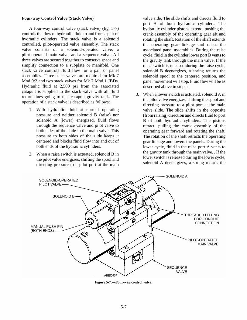
Four-way Control Valve (Stack Valve)
A four-way control valve (stack valve) (fig. 5-7)controls the flow of hydraulic fluid to and from a pair ofhydraulic cylinders. The stack valve is a solenoidcontrolled, pilot-operated valve assembly. The stackvalve consists of a solenoid-operated valve, apilot-operated main valve, and a sequence valve. Allthree valves are secured together to conserve space andsimplify connection to a subplate or manifold. Onestack valve controls fluid flow for a pair of panelassemblies. Three stack valves are required for Mk 7Mod 0/2 and two stack valves for Mk 7 Mod 1 JBDs.Hydraulic fluid at 2,500 psi from the associatedcatapult is supplied to the stack valve with all fluidreturn lines going to that catapult gravity tank. Theoperation of a stack valve is described as follows:
1. With hydraulic fluid at normal operatingpressure and neither solenoid B (raise) norsolenoid A (lower) energized, fluid flowsthrough the sequence valve and pilot valve toboth sides of the slide in the main valve. Thispressure to both sides of the slide keeps itcentered and blocks fluid flow into and out ofboth ends of the hydraulic cylinders.
2. When a raise switch is actuated, solenoid B inthe pilot valve energizes, shifting the spool anddirecting pressure to a pilot port at the main
valve side. The slide shifts and directs fluid toport A of both hydraulic cylinders. Thehydraulic cylinder pistons extend, pushing thecrank assembly of the operating gear aft androtating the shaft. Rotation of the shaft extendsthe operating gear linkage and raises theassociated panel assemblies. During the raisecycle, fluid in the cylinder lower port B vents tothe gravity tank through the main valve. If theraise switch is released during the raise cycle,solenoid B deenergizes, a spring returns thesolenoid spool to the centered position, andpanel movement will stop. Fluid flow will be asdescribed above in step a.
3. When a lower switch is actuated, solenoid A inthe pilot valve energizes, shifting the spool anddirecting pressure to a pilot port at the mainvalve slide. The slide shifts in the opposite(from raising) direction and directs fluid to portB of both hydraulic cylinders. The pistonsretract, pulling the crank assembly of theoperating gear forward and rotating the shaft.The rotation of the shaft retracts the operatinggear linkage and lowers the panels. During thelower cycle, fluid in the raise port A vents tothe gravity tank through the main valve. . If thelower switch is released during the lower cycle,solenoid A deenergizes, a spring returns the
5-7
SOLENOID-OPERATEDPILOT VALVE
SOLENOID B
MANUAL PUSH PIN(BOTH ENDS)
SOLENOID A
THREADED FITTINGFOR CONDUITCONNECTION
PILOT-OPERATEDMAIN VALVE
SEQUENCEVALVE
ABEf0507
Figure 5-7.—Four-way control valve.
5-8
BLEEDVALVE
VENTPIPING
HOSEASSEMBLY
CAPASSEMBLY
BLEEDVALVE
ABEF0508
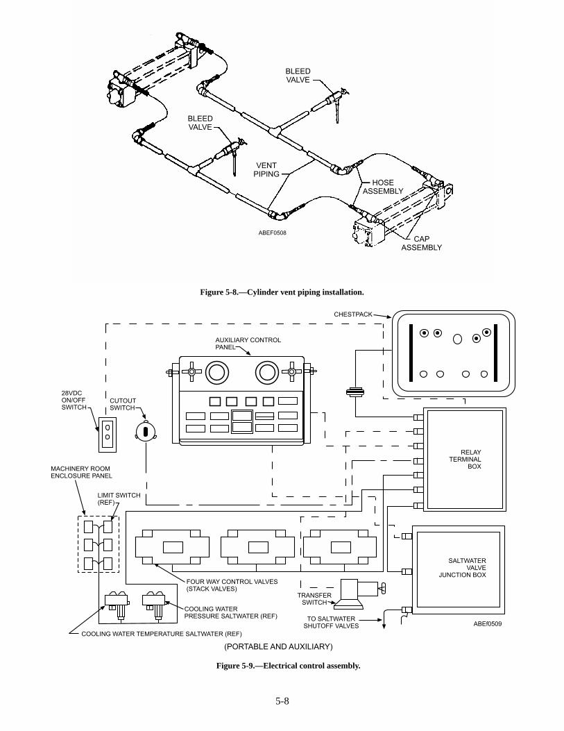
Figure 5-8.—Cylinder vent piping installation.
TRANSFERSWITCH
TO SALTWATERSHUTOFF VALVES
COOLING WATERPRESSURE SALTWATER (REF)
COOLING WATER TEMPERATURE SALTWATER (REF)
FOUR WAY CONTROL VALVES(STACK VALVES)
MACHINERY ROOMENCLOSURE PANEL
LIMIT SWITCH(REF)
CUTOUTSWITCH
28VDCON/OFFSWITCH
AUXILIARY CONTROLPANEL
RELAYTERMINAL
BOX
SALTWATERVALVE
JUNCTION BOX
(PORTABLE AND AUXILIARY)
ABEf0509
CHESTPACK
Figure 5-9.—Electrical control assembly.

solenoid spool to the centered position andpanel movement will stop. Fluid flow will be asdescribed earlier in step a.
Cylinder Vent Piping Installation
The cylinder vent piping installation (fig. 5-8)consists of bleed valves, flexible hose assemblies,piping, and associated fittings. Each JBD hydrauliccylinder is vented through flexible hoses connected tovent ports directly above the cylinder raising andlowering ports. The hoses also connect the piping to anearby vent station and bleed valves.
ELECTRICAL CONTROL ASSEMBLY
The electrical assembly consists of the deckedge,auxiliary and portable (chestpack) control panels, atransfer switch, relay terminal box, cutout switch, andassociated wiring and connectors. All JBD assembliesare electrically controlled by means of the individualcontrol panels. Each control panel and chestpack has itsown electrical installation and each is operatedindependently of the other. An auxiliary control paneland transfer switch, located below deck, is provided foremergency operating purposes. The auxiliary controlpanel is identical to the deckedge panel.
Deckedge and Auxiliary Control Panels
The deckedge and auxiliary control panels (fig.5-10) are identical in design. The Mk 7 Mod 0/2 controlpanels contain nine light switches while the Mk 7 Mod1 panels contain seven light switches. Each panel alsocontains four fuse lights, a power on light switch,double indicator light, a cooling water and hydraulicfluid shutoff valve, and a cooling water and hydraulicpressure gauge. Six switches (Mk 7 Mod 0/2) or fourswitches (Mk 7 Mod 1) are used to raise and lower theJBD panels. Two switches are push-to-test and the lastswitch is an emergency cooling water shut off valvelight switch (water-emer-off). The water-emer-offswitch, when actuated, closes a remote-controlledshutoff valve in the saltwater line leading to theapplicable JBD assembly. The fuse light will provide anindication of a blown fuse and possible trouble in theapplicable circuitry. The double indicator lights willprovide an indication of low cooling water pressure orhigh cooling water temperature. A plastic guard,mounted over the up and down switches, preventsaccidental operation of the panels.
Chestpack Portable Control Assembly
The chestpack (fig. 5-11) contains three individualraise and lower toggle switches, an “all” raise and lowertoggle switch, a defeat interlock toggle switch, anemergency cooling water toggle switch, and a yellowwater indicator light. Electrical power is provided by anumbilical cable connected to a receptacle on the rear ofthe chestpack and another receptacle located in thedeck. The defeat interlock switch permits raising andlowering the JBDs during emergencies, such as lowcooling water pressure or high cooling watertemperature. The emergency cooling water switch,when actuated, closes a motor operated shutoff valve inthe saltwater line leading to the applicable JBDassembly. The yellow cooling water indicator light,when lit, indicates a malfunction within the coolingwater system. The three individual raise and lowerswitches allow the operator to raise individual pairs ofpanels while the “all” raise switch permits raising andlowering of all panels simultaneously. The red (port)and green (stbd) indicator lights show the operator towhich JBD the chestpack is connected. All JBDinstallations currently use the deckedge control for JBDnumber four. Handles are provided on each chestpackto attach a harness worn by the JBD operator.
Transfer Switch (Chestpack Portable ControlSystem)
The transfer switch (fig. 5-12) for the chestpackportable control is a rotary type with a rotary dial. Thedial face is identified with two “portable” and two“aux” positions. The transfer switch is located near theapplicable auxiliary control panel. When the transferswitch is in the portable position, the chestpack isoperable. Moving the dial to the aux position shiftselectrical power from the chestpack to the auxiliarypanel.
Transfer Switch (Deckedge Control System)
The transfer switch is a rotary type switch with arotary dial. The dial face is identified with two“deckedge” and two “aux” positions. The transferswitch is located near the applicable auxiliary controlpanel. When the transfer switch is in the deckedgeposition, the deckedge control panel is operable.Moving the dial to the aux position shifts electricalpower from the deckedge panel to the auxiliary panel.The only difference between the chestpack and thedeckedge transfer switch is the dial face.
5-9

5-10
COOLING-WATERPRESSURE
CONNECTION
SWITCHGUARD
JET BLAST DEFLECTORDOWN SWITCHES
COOLING-WATERPRESSURE
FUSELIGHT
SW PRESSURESW TEMPERATURE
PUSH-TO-TESTLIGHT SWITCHES
COVER
(MK 7 MOD 0/2)
COOLING-WATERPRESSURE
HYDRAULICPRESSURE
FUSELIGHT
EMERGENCYCOOLING-WATERSHUTOFF SWITCH
SW PRESSURESW TEMPERATURE
POWER-ONSWITCH
PUSH-TO-TESTLIGHT SWITCH
COVER
JET BLAST DEFLECTORDOWN SWITCHES
JET BLAST DEFLECTORUP SWITCHES
SWITCHGUARD
COOLING-WATERPRESSURE
CONNECTION
POWER-ONSWITCH
HYDRAULICPRESSURE
EMERGENCYCOOLING-WATERSHUTOFF SWITCH
JET BLAST DEFLECTORUP SWITCHES
ABEf0510(MK 7 MOD 1)
Figure 5-10.—Deckedge and auxiliary control panels.
LIGHT STBD(GREEN)
LIGHT PORT(RED) SWITCH DEFEAT
INTERLOCK LIGHT WATER(YELLOW)
SWITCH WATER
PROTECTIVECOVER
SWITCHALL RAISE
SWITCHRIGHT
SWITCHCENTER
SWITCH LEFT
SWITCH PANEL
HANDLE
ABEf0511
STBD PORT
WATER
OFF
RAISE
LOWER
RAISE
LOWER
RAISE
LOWER
RAISE
LOWER ALL
DEFEATINTERLOCK
Figure 5-11.—Chestpack portable control assembly.

PANEL SUPPORT INSTALLATION ANDEMERGENCY LOWERING DEVICEINSTALLATION
The panel support and emergency lowering deviceinstallation (fig. 5-13) consists of the panel supportstanchions, panel supports, and an emergency loweringdevice. Panel support stanchions are to be used anytimepanel supports are being installed or removed. Thepanel support stanchions are positioned between theraised JBD panel and lip of the flight deck. The panelsupport stanchion is designed to support the weight of apair of fully raised JBD panels; however, the stanchionwill not prevent the lowering of JBDs under pressure.
To provide a total margin of safety, panel supportsmust be property installed prior to any maintenance
5-11
ROTARY DIAL
ABEF0512
Figure 5-12.—Transfer switch (Chestpack control system).
INSTALLQUICK-RELEASE PINTHRU BRACKETAND THRU PANELSUPPORT AS SHOWN
PANELSUPPORT
EYE ON LINKAGE
FLIGHT DECK
SEE VIEW B
PANELSUPPORT
STRUCTURALSTOP PANEL SUPPORT
(SEE VIEW A)
PANEL SUPPORTSTANCHION
JBD PANEL
FLIGHT DECK
OPERATING LINKAGE
VIEW B
VIEW A
ABEf05013
JBD PIT
EMERGENCYLOWERINGBAR
EMERGENCY LOWERING DEVICE
Figure 5-13.—Panel support and emergency lowering installation.

being conducted under JBD panels. The panel supportsattache to the JBD operating linkage arm assembly,with a quick release pin and fit into an indentation in thedepressed deck area (JBD pit) at the forward end. Thepanel supports are used to lock panels in the raisedposition for maintenance purposes or emergencies. Apanel support is provided for each set of operating gear,three supports for Mk 7 Mod 0/2 and two for Mk7 Mod1 JBDs.
The emergency lowering device connects to a towtractor on one end and fits against the operating linkagearm assembly at the other end. This allows the tractor topush the operating linkage “over-center”. With theemergency bypass valves open, the weight of the panelswill then force fluid from the raise end of the hydrauliccylinders through the emergency bypass valvepermitting the panels to slowly lower.
Preparation for Use
When the JBDs are put in operation for the firsttime or after being idle, use the following procedures:
1. Perform the preoperational inspection accord-ing to the applicable maintenance requirementcard (MRC).
2. Ensure that personnel, aircraft, and flight deckequipment are clear of the panel area beforeattempting to raise the JBDs.
CAUTION
Damage by excessive heat can result fromjet engine exhaust if cooling water is notflowing at the correct pressure.
3. Check to ensure salt water supplied from theship's fire main is flowing through thewater-cooled panels.
4. Functionally test the JBD hydraulic andelectrical system for proper operation andleaks.
EMERGENCY OPERATION PROCEDURES
In the event of an emergency or a malfunction, theprocedures discussed in the following paragraphs mustbe followed. The emergency lowering of a JBD willrequire a minimum of eight personnel:
• Topside Safety Petty Officer (overall in charge)
• Topside JBD phone talker
• Below decks phone talker/Valve operator
• Two personnel to install emergency loweringdevice
• Two safety observers (stationed at the port andstarboard sides of the JBD panels)
• Tractor driver
Electrical Control Failure
Should the chestpack, deckedge, and auxiliarycontrol panels become affected by an electrical powerfailure and the hydraulic system is functional, proceedas follows:
1. Station a crewperson to act as a valve operatorat the stack valves. The valve operator shall beequipped with a sound-powered phone set. Thechestpack or JBD deckedge operator shallremain at his or her station and relayinstructions to the valve operator. The JBDdeckedge or auxiliary panel operator shall alsomonitor the pressure gauges.
2. The valve operator, when instructed by thechestpack or JBD deckedge operator, shallraise or lower the JBD panels by the manualpush pins of the A and B solenoids of the stackvalves. The B solenoid controls the raising ofthe panels, and the A solenoid controls thelowering.
Hydraulic Control Failure
Should the JBD hydraulic system fail with theJBDs in the FULL-UP position, the followingprocedures must be used to lower the panels:
1. Establish sound-powered phone communica-tion between the valve operator and thechestpack or deckedge operator.
WARNING
Ensure all tag-out procedures areaccording to current shipboard instructions.
2. Close the main supply valve and attach a safetytag.
3. Open the applicable emergency bypass valvesone-quarter turn or as necessary to control thelowering speed of the panel.
4. Using the panel emergency-lowering device,place the fitted end against the panel linkage
5-12

arm and attach the ring end to a tractor towhook. Push with the tractor until the operatinggear linkage unlocks.
WARNING
Once the emergency lowering device isinstalled, all hands shall stand back at a safedistance from the JBD and around tractor. Asthe JBD begins to lower, the emergencylowering device will be dragged out of the JBDpit by the tractor utilizing reverse gear.
5. Adjust the panel lowering speed byopening/closing the emergency bypass valve.
6. Once the strut is over-center, the JBD panelswill fall under its own weight until it is flushwith the deck.
Inoperative Deckedge Control Panel or PortableElectrical System Control Box
In the event of an emergency where the chestpackor the deckedge control panel cannot be used, theauxiliary control panel becomes operational.
1. Station a crewperson at the flight deck ordeckedge to man the phone and relayinstructions to the auxiliary-control-paneloperator.
WARNING
The crewperson, acting as a safetyobserver, should ensure that the area around theJBD is clear of aircraft, support equipment, andpersonnel.
2. With the transfer switch in the AUX position,the auxiliary-control-panel operator shalloperate the panel by the instructions relayed tohim or her from the flight deck or deck edgepersonnel.
CAUTION
Repair and checkout of the faulty panel orcontrol box operation shall be accomplished attimes when the raising or lowering of the JBDwould not be prohibited by aircraft movementon the flight deck.
3. Continue operation of the auxiliary controlpanel until the faulty chestpack or deckedge
control panel is completely checked out andrestored to proper operating condition.
WARNING
Prior to returning control back to deckoperation, verify with the flight deck safetyobserver that the area around the JBD is clearof aircraft, support equipment, and personnel.
4. Return control of the JBD to the chestpack ordeckedge operator.
MAINTENANCE
This section contains preventive and correctivemaintenance information and procedures, some ofwhich are general and apply to various items of thesystem and others which are specific and apply to aparticular part of the equipment.
Planned Maintenance
The planned maintenance system furnishes allvessels and stations with MRCs containing specificmaintenance instructions. These cards are used atrequired frequencies to maintain JBD equipment inoperating condition and to prevent breakdown andsubsequent shutdown of operations. The plannedmaintenance system and the maintenance datacollection system are described in OPNAVINST4790.4.
Current MRCs include the following inspectionand cleaning procedures:
1. Preoperational inspections
2. Postoperational inspections
3. Cleaning and inspecting hydraulic pipingorifice plate(s)
WARNING
Before performing any maintenanceprocedures behind a JBD panel in the raisedposition, install the panel supports to preventthe panel from lowering. Failure to do thiscould result in serious injury to personnel.
To ensure dependable operation of the JBDequipment, proper lubrication of the mechanicallinkage is essential. Lubrication is part of thepreoperational checks given in the MRC. Extensiontubes are provided on trunnion bearings and hydraulic
5-13

cylinder bracket assemblies so that all lube fittings canbe reached from the deck.
PROTECTING OPEN EQUIPMENT.—Whenremoving a component from the hydraulic system, capor plug all openings to prevent entry of foreign matter.Use tape to protect pipe threads.
CLEANING.—Hydraulic system componentsmust be disassembled, cleaned, repaired, andreassembled as specified in the operation, maintenance,and overhaul instructions manual for the specific typeof JBD installation on your ship.
WARNING
Before repairing or removing anycomponents connected to hydraulic or waterlines, make sure the lines are depressurized.Also, before repairing or removing any elec-trical component, de-energize the electricalcircuit and attach an out-of-service tag.
HOSES, SEALS, AND O-RINGS.—Hoses,seals, and O-rings are selected on the basis of theircompatibility with the hydraulic fluid. Therefore,replacement parts should be of the same material asoriginal parts. O-rings must be removed and replacedwith care to avoid damage to the O-ring and O-ringsealing surfaces of the various parts. O-rings must befree of cuts and not deformed. New O-rings must beinstalled at every reassembly of components. Beforeassembly, all O-rings must be lightly lubricated withthe system hydraulic fluid. Hoses are subject to wearand require periodic replacement. When installinghoses, take care to avoid unnecessary bends andoverstressing.
To restore the JBD system to operating conditionafter a down period that required draining fluid,perform preoperational inspection procedures given inthe applicable MRC.
For most repairs to the hydraulic system, onlyportions of the system need be drained. Isolation valvesin each of the hydraulic cylinder lines and a shutoffvalve between the stack valve and the catapult pumpspermit isolation of portions of the JBD hydraulicsystem.
Troubleshooting
Most problems that occur on JBDs can berecognized as a failure of one of threesystems—namely, hydraulic, electrical, or water.
Information that allows operating and maintenancepersonnel to locate the source of problems orequipment failure is found in the JBD technical manual,in the section covering trouble shooting.
SAFETY PRECAUTIONS
The energy required to operate the JBD is suppliedby fluid under pressure; therefore, when operating withfluid under pressure, observe standard safetyprecautions that apply.
All moving parts and equipment should be checkedfor rags, tools, or other foreign material beforeoperating any of the machinery. Only qualifiedoperators shall be allowed to operate the JBDs.
The parking of aircraft on the deflector panelshould be avoided. The panels are designed towithstand only the temporary weight of the aircrafttaxiing over them.
When you perform maintenance on the JBD,comply with the safety precautions listed on the MRC.
Personnel and equipment shall be clear of the JBDmachinery enclosure and depressed deck when thepanels are being raised or lowered. This includes thetimes when the panels are being operated duringpreoperational inspections and maintenance oroverhaul tests and inspections.
REVIEW QUESTIONS
Q1. What provides the means of physically raisingand lowering the JBD panels?
Q2. Each Mk 7 Mod 0 JBD panel assemblyconsists of how many tube assemblies?
Q3. What permits rotational movement of thepiping as the JBD is raised and lowered?
Q4. What is the maximum temperature of thecooling water?
Q5. What controls the hydraulic fluid to and fromthe hydraulic cylinders?
Q6. What type of valve is the stack valve?
Q7. What is the differences between the deckedgeand the auxiliary control panel?
Q8. The double indicator light will provide whatindication?
Q9. What is the function of the “all” raise switchon the chestpack portable control?
5-14

Q10. What is the function of the panel support?
Q11. List the personnel required to perform a JBDemergency lowering?
MK 2 NOSE-GEAR-LAUNCH (NGL)SYSTEM
LEARNING OBJECTIVES: Describe thecomponents of the Mk 2 nose gear launchsystem. Describe the operations of the Mk 2nose gear launch system.
The nose-gear-launch (NGL) equipment isdesigned to assist in the launching of aircraft byproviding a positive and automatic means of attachingthe aircraft launch bar to the catapult shuttle andspreader. This method of launching permits a positive,automatic engagement of aircraft to catapult.Automatic engagement of the aircraft launch bar to thecatapult reduces the number of personnel required to bein close proximity to the aircraft during catapulthookup.
The major components of the Mk 2 NGL systeminclude the flush-deck guide track, slide assembly,
actuator reset assembly, shuttle spreader, and buffercylinder assembly. These components and theiroperation are discussed in the following paragraphs.
NOSE-GEAR-LAUNCH GUIDE TRACKS
The guide tracks (fig. 5-14), which guides theaircraft launch bar into engagement with the catapultshuttle spreader assembly consists of an approachtrack, buffer-cylinder track, aft slide-access track,forward slide-access track, and a forward track. Theapproach track contains a V-shaped mouth, whichguides the aircraft launch bar into the guide track.Grooves constructed in the individual tracks and topsurface of the buffer cylinder guide the launch bar as theaircraft moves forward. Inserts installed in the forwardslide-access tracks provide a camming surface, whichensures that the launch bar makes positive contact thebuffer hook actuator roller. Inserts installed in theforward track guide the launch bar up and over thespreader assembly for proper launch bar to shuttlehookup.
Wheel guides bars are provided to guide the aircraftnose wheel along the guide track. The inner wheel
5-15
INSERTSSTATION 1
TROUGH COVER(REF)
FWD TRACKFWDSLIDE-ACCESSTRACK
INSERTS
AFTSLIDE-ACCESSTRACK
NOSEWHEEL TIREINNER GUIDE BARS
BUFFER CYLINDERTRACK
AFT PORTABLETROUGH COVER
(REF)
END OF INNERGUIDE BARS
NOSEWHEEL TIREOUTER GUIDE BARS
(REF)
STATION 0(REF)
REMOVABLE INNERWHEEL GUIDE BARS
APPROACH TRACK
ABEf0514
Figure 5-14.—Nose-gear-launch guide tracks.

guide bars keep the nosewheel straight during forwardmovement. The outer wheel guide bars prevent the nosewheel from sliding side to side once the nosewheelclears the inner guide bars and aid in proper alignmentof launch bar to spreader assembly.
NOSE-GEAR-LAUNCH (NGL) ASSEMBLY
The NGL assembly consists of the slide assembly,reset assembly, forward and aft slide-access tracks,buffer cylinder assembly, tensioner cylinder assembly,housing, drain pan assembly, and a shock absorber.
Slide Assembly
The slide assembly (fig. 5-15) consists of a bodycontaining rollers, which reduce friction duringforward and aft movement of the assembly; the bufferhook, which engages the aircraft hold-back bar; and thebuffer-hook actuator assembly, which raises the bufferhooks to flight deck level. The slide assembly ismechanically connected to the buffer-cylinder pistonrods by three links.
5-16
LAUNCH BAR
BUFFER HOOK
ACTUATOR LEVER
RESETASSEMBLY
RESETSLIDER
ROLLER
BUFFER HOOKACTUATOR ASSEMBLY
VIEW BBUFFER HOOK RESET
VIEW ABUFFER HOOK ACTUATION
RESET ASSEMBLY
ABEf0515
BUFFER HOOK
Figure 5-15.—Slide assembly.

During operation, (see view A, fig. 5-15) as theaircraft moves forward, the launch bar, sliding in thetrack-guide grooves, contacts the buffer- hook-actuator-assembly roller, forcing it to rotate forwardand down. When the buffer hook actuator is forceddown, its forces against the underside of the buffer hookand raises the hook into position to engage the aircraftholdback bar. As the aircraft continues forward, theholdback bar engages the buffer hook and pulls theslide assembly forward. The slide assembly, connectedto the buffer cylinder piston rods, pulls the three rodsfrom the buffer cylinder assembly. Hydraulic resistancewithin the buffer cylinder assembly decelerates theaircraft. When the aircraft stops, it is in position forcatapult shuttle hookup.
After launch, the piston rods are retracted into thebuffer cylinder assembly automatically. As the slideassembly moves aft, the buffer hook assembly contactsthe reset assembly slider (see view B, fig. 5-15),causing the actuator lever to rotate down. This actionpermits the buffer hook to drop below deck levelthrough an opening in the track into the deck housing.The slide assembly is now ready for the next aircrafthookup.
Reset Assembly
The reset assembly (fig. 5-16), which resets thebuffer hook, causing it to drop below deck at the end ofthe buffer-cylinder-assembly retract stroke, is locatedbelow the slide assembly in the deck housing. The resetassembly consists of a housing, slider, slider actuatingspring, and retainer. The slider contains a stellite
surface that reduces wear due to contact with the bufferhook actuator lever. Grooves machined in the top of theslider provide a path for the flow of lubricant betweenthe slider and the inner walls of the housing. Thehousing is chrome-plated to prevent corrosion. Theactuating spring is housed in a hole in the bottom of theslider. The slider and spring are secured in the housingby means of the retainer.
During operation when the slide assembly isforward, the reset-assembly slider is not restrained bythe actuator assembly but is held above the surface ofthe housing by the slider actuating spring. After launch,as the slide assembly retracts, the buffer hook actuatorcontacts the extended reset slider, causing the actuatorassembly to rotate downward. This action permit thebuffer hook to drop below the deck through the trackopening into the deck housing cavity (see view B, fig.5-15). When the buffer hook is below deck, the actuatorassembly lever holds the reset-assembly slider down inthe reset assembly housing.
Forward and Aft Slide-Access Tracks
The slide-access tracks retain the slide assembly inthe housing. They also serve to guide the aircraft launchbar to ensure proper engagement with the catapultshuttle spreader. Inner and outer guide wheel bars areattached to the aft and forward slide-access track tokeep the aircraft nosewheel straight during forwardmovement of the aircraft. Inserts installed in theforward slide-access tracks provide a camming surface,which ensure that the launch bar contacts the bufferhook actuator roller.
5-17
LUBE FITTING
HOUSING
SLIDER
ACTUATINGSPRING
RETAINER
SLIDER
RETAINER
LUBEFITTING
HOUSING
VIEW AABEF0516
Figure 5-16.—Reset assembly.

Buffer Cylinder Assembly
The NGL buffer cylinder (fig. 5-17) is located inthe deck housing between the approach track and the aftslide-access track. The buffer-cylinder body hasintegral guide tracks on its top surface and containsthree hydraulic cylinders. The two outer cylinderscontain hollow piston rods; the center cylinder pistonrod is solid. The forward end of each piston rod isattached to the slide assembly. Within each outer pistonrod is an orifice tube, which meters fluid flow throughthe outer cylinders to absorb the forward energy of theaircraft during the buffering stroke.
Prior to aircraft holdback bar/buffer hookengagement, the buffer cylinder assembly is in thestandby cycle (fig. 5-18) with the three piston rods fullyretracted into the buffer cylinders. While in the standbycycle, hydraulic fluid is constantly circulated betweenthe hydraulic system and the buffer cylinder assemblythrough two metering orifice screws at a rate ofapproximately 8.5 gpm. This metered flow, which isnonadjustable, is to maintain the hydraulic fluid in thesystem at the proper temperature.
When the aircraft holdback bar engages the bufferhook, the slide assembly moves forward, pulling thethree piston rods from the cylinders. As the piston rodsmove forward, fluid in front of each outer-cylinderpiston is forced through the holes around the peripheryof each outer-cylinder piston and through the meteringholes in the two orifice tubes. As the pistons continueforward, the number of metering holes in the orifice
tubes is progressively reduced, causing an increasingresistance to forward motion of the slide assembly, thusdecelerating and bringing the aircraft to a smooth stopat the end of the buffing stroke.
During the buffing stroke, fluid in front of thecenter-cylinder piston is forced through a port in thecylinder and through the hydraulic line into the NGLvalve-manifold accumulator, which acts as a cushionand fluid reservoir. After launch, the fluid pressureestablished by the valve-manifold reducing valveacting on the forward side of the center cylinder forcesthe center piston aft, thus retracting the three rods intothe cylinders.
Buffer Accumulator Assembly
The buffer accumulator assembly (fig. 5-19) islocated below deck in line with and aft of the buffercylinder assembly. The buffer accumulator consists of ahydraulic accumulator mounted in a support with a teefitting and associated hardware.
During operation, as the buffer cylinder piston rodsare pulled forward, hydraulic fluid flows from theaccumulator, through the tee fitting and associatedpiping into the aft end of the buffer cylinder assemblyfilling the void created as the piston rods move forward.
After the launch, the buffer piston rods retract intothe buffer cylinder forcing fluid from the buffercylinder back to the accumulator. Fluid continues toflow into the accumulator until the pressure buildupexceeds the spring-load of the check valve located
5-18
BLEEDER PLUG
METER SCREW BODY
METER SCREW
PISTON RODS
ABEf0517
Figure 5-17.—Buffer cylinder assembly.

down stream from the accumulator. Opening of thecheck valve permits excess fluid from the buffercylinder to be returned to the catapult gravity tank.
Drain Pan Assembly
The drain pan assembly (fig. 5-20) is located on theunderside of the NGL assembly directly below thetensioner cylinder. The drain pan supports and protectsthe two quick disconnect, self sealing hydraulic
5-19
HLP RETURN
HMP SUPPLY
NORMAL SYS PRESSURE
DRAIN
PILOT PRESSURE
HY
DH
YD
SOL BSOL A
HYDHYD
ABEf0518
Figure 5-18.—Standby cycle.
SUPPORT
AIR FILTER
ACCUMULATOR
PIPE FITTING
ABEf0519
Figure 5-19.—Buffer accumulator assembly.
DRAIN PAN ASSEMBLY
ABEf0520
Figure 5-20.—Drain pan assembly.

coupling which connects the tensioner cylinder to thecatapult hydraulic system. The drain also provides areservoir and drain for all fluids entering the track slot.
Shock Absorber (Soft-Stop) Assembly
The shock absorber assembly (fig. 5-21) ismounted horizontally at the forward end of the NGLassembly. During the catapult retract cycle, the shockabsorber provides uniform deceleration of the shuttle tobring it to a smooth, soft stop, eliminating impact forcesthat could cause damage to the grab assembly or theNGL assembly. The shock absorber is a compact,self-contained, sealed unit consisting of an all steelbody with an inner pressure chamber and an all steelchrome-plated piston rod that requires no maintenanceor adjustments.
Valve Manifold Assembly
The valve manifold assembly (fig. 5-22) controlsthe flow of fluid from the catapult hydraulic system tothe buffer cylinder assembly. The valve manifoldassembly is located below decks and consists of asupport structure, two two-way flow control valves,two four-way solenoid control valves, a reducing valve,a piston-type accumulator, a terminal box to houseelectrical connections, and associated piping.
5-20
ABEf0521
Figure 5-21.—Shock absorber assembly.
PORT RREDUCED PRESSURE
TO BUFFERCYLINDER
CHECK VALVE
PORT TRETURN
TO GRAVITYTANK
PORT SFROM BUFFERACCUMULATOR
CHECKVALVE
FLOWCONTROL
VALVE
SUPPORTSOLENOID A
SOLENOID CONTROLVALVE
ACCUMULATOR
SOLENOID B
DRAIN
FLOWCONTROL
VALVE
PORT PHYDRAULIC
SUPPLY
REDUCINGVALVE
ABEf0522
Figure 5-22.—Valve manifold assembly.

NOSE-GEAR-LAUNCH CONTROL SYSTEM
On ICCS ships the operation of the NGLequipment is automatic under normal operatingconditions. The only controls provided are the bufferfwd and the buffer aft push buttons installed on themonitor control console, deckedge, and the centralcharging panel (CCP).
On non-ICCS ships, the operation of the NGLequipment is automatic under normal operatingconditions. Two control panels (fig. 5-23) are providedfor the operation of the NGL system. One panel islocated adjacent to the catapult deckedge station for useduring normal operations. A second panel is located inclose proximity to the aft end of the catapult trough foremergency operations. The control panels are identicaland houses a relay, terminal board, power on indicatorlight, buffer fwd and buffer aft switches with integralindicator lights and associated wiring. Panel selectionis made by rotating a transfer switch (fig. 5-24) from itsnormal position to its emergency position.
OPERATIONS
Buffer Forward
The buffer forward push button is used during anaircraft launch abort operation to move the buffer hookforward of the holdback bar so that the release elementand holdback bar can be removed from the aircraft.
When the BUFFER FWD push button is pressed,the buffer forward solenoid (A) is energized (fig. 5-25),shifting the buffer forward solenoid valve, allowingmedium-pressure hydraulic fluid to shift the piston ofthe flow control valve. When the piston of the flowcontrol valve shifts, fluid flow from the aft end of thebuffer cylinder assembly to the gravity tank is shut off.This causes a pressure buildup on the aft end of thebuffer cylinder assembly pistons. Since the area on theaft side of the pistons is larger than the area on theforward side, the pistons, piston rods, and attached slideassembly are driven forward.
Buffer Aft
The buffer aft push button is pressed during anabort operation when the aircraft holdback bar isconnected to the buffer hook; the fluid pressure actingon the forward side of the buffer pistons will tow theaircraft aft. When the buffer has moved back 4 to 10inches, the abort force is reduced because hydraulicpressure is bled off through exposed holes in thebuffer-cylinder assembly orifice tubes. Aircraft brakingis required prior to releasing the push button to hold theaircraft against its thrust load. When the NGL BUFFERAFT push button is pressed after the aircraft is removedfrom the catapult and the buffer hook is forward,hydraulic fluid pressure will return the pistons, pistonrods, and slide assembly fully aft. When the slideassembly is retracted, the buffer hook returns to aposition below deck.
When the BUFFER AFT pushbutton is pressed, thebuffer aft solenoid (B) is energized (fig. 5-26), shiftingthe buffer aft solenoid valve, allowing medium-pressure hydraulic fluid to shift the piston of the flowcontrol valve. Medium-pressure hydraulic fluid flowsthrough the flow control valve to the buffer cylinder
5-21
ABEf0523
Figure 5-23.—Deckedge and emergency control panel.
ABEf0524
Figure 5-24.—Transfer switch.

5-22
HLP RETURN
HMP SUPPLY
NORMAL SYS PRESSURE
DRAIN
PILOT PRESSURE
HY
DH
YD
SOL BSOL A
HYDHYD
ABEf0525
Figure 5-25.—Abort aircraft-buffing forward cycle.
HLP RETURN
HMP SUPPLY
NORMAL SYS PRESSURE
DRAIN
PILOT PRESSURE
HY
DH
YD
SOL BSOL A
HYDHYD
ABEf0526
HLP RETURN
HMP SUPPLY
NORMAL SYS PRESSURE
DRAIN
PILOT PRESSURE
HY
DH
YD
SOL BSOL A
HYDHYD
Figure 5-26.—Abort aircraft-buffing aft cycle.
assembly. Fluid pressure is applied to the forward sideof the buffer pistons; and the pistons, piston rods, andslide assembly move aft. As the pistons move aft, fluidis forced out of the aft end of the buffer cylinderassembly, through a check valve and the other flowcontrol valve, to the gravity tank.
REVIEW QUESTIONS
Q12. List the NGL guide tracks.
Q13. The slide is mechanically connected to whatcomponent?
Q14. What component resets the buffer hooks?
Q15. What ensures the launch bar makes contactswith the buffer hook actuator roller?
Q16. The orifice tube is located in which cylinderof the buffer cylinder assembly?
Q17. The void created as the piston rods moveforward is filled with hydraulic fluid fromwhat assembly?
Q18. On ICCS ships, the buffer fwd and buffer aftpushbuttons are installed on what controlpanels?
SUMMARY
In this chapter we have discussed the functions andoperating procedures for the JBDs and Mk 2 NGLequipment. For additional, in-depth descriptions of thisequipment, see the applicable NAVAIR technical man-uals.
5-23