Assistive Guitar Plucking Device and User Interface
195
Worcester Polytechnic Institute Digital WPI Major Qualifying Projects (All Years) Major Qualifying Projects April 2019 Assistive Guitar Plucking Device and User Interface Benjamin David Shaffer Worcester Polytechnic Institute Daniel J. Farnitano Worcester Polytechnic Institute Laurel Higham Worcester Polytechnic Institute Victoria Nicole Mercouris Worcester Polytechnic Institute Follow this and additional works at: hps://digitalcommons.wpi.edu/mqp-all is Unrestricted is brought to you for free and open access by the Major Qualifying Projects at Digital WPI. It has been accepted for inclusion in Major Qualifying Projects (All Years) by an authorized administrator of Digital WPI. For more information, please contact [email protected]. Repository Citation Shaffer, B. D., Farnitano, D. J., Higham, L., & Mercouris, V. N. (2019). Assistive Guitar Plucking Device and User Interface. Retrieved from hps://digitalcommons.wpi.edu/mqp-all/7022
Transcript of Assistive Guitar Plucking Device and User Interface
Worcester Polytechnic InstituteDigital WPI
Major Qualifying Projects (All Years) Major Qualifying Projects
April 2019
Assistive Guitar Plucking Device and User InterfaceBenjamin David ShafferWorcester Polytechnic Institute
Daniel J. FarnitanoWorcester Polytechnic Institute
Laurel HighamWorcester Polytechnic Institute
Victoria Nicole MercourisWorcester Polytechnic Institute
Follow this and additional works at: https://digitalcommons.wpi.edu/mqp-all
This Unrestricted is brought to you for free and open access by the Major Qualifying Projects at Digital WPI. It has been accepted for inclusion inMajor Qualifying Projects (All Years) by an authorized administrator of Digital WPI. For more information, please contact [email protected].
Repository CitationShaffer, B. D., Farnitano, D. J., Higham, L., & Mercouris, V. N. (2019). Assistive Guitar Plucking Device and User Interface. Retrievedfrom https://digitalcommons.wpi.edu/mqp-all/7022

Assistive Guitar Plucking Device
and User Interface
A Major Qualifying Project Report Submitted to the Faculty
of WORCESTER POLYTECHNIC INSTITUTE
in Partial Fulfillment of the Requirements
for the Degree of Bachelor of Science by:
Daniel Farnitano
Laurèl Higham
Victoria Mercouris
Benjamin Shaffer
Professor Holly K. Ault, Advisor
Professor Curtis A. Abel, Co-advisor
Submitted on April 24, 2019
This report represents the work of WPI undergraduate students. It has been
submitted to the faculty as evidence of completion of a degree requirement. WPI
publishes these reports on its website without editorial or peer review.

i
Abstract
Every individual should have the opportunity to experience musical creation; however,
not everyone can play instruments as they are designed. Music provides people an avenue to
express their emotions and has been shown to stimulate the brain in uniquely beneficial ways.
Very few products exist in the marketplace that enable accessible means of music playing; yet,
millions of individuals in the United States live with physical disabilities. The goal of the project
was to develop a wireless, battery-powered device with a plucking mechanism and a wearable
user interface (UI) that would enable individuals with physical disabilities to play a guitar. The
device is to be used in conjunction with a guitar fretting device built by the project sponsor, Kurt
Coble. The plucking mechanism, mounted to an adjustable frame around the guitar, has 3D
printed plectra to actuate each guitar string, driven by servo motors. The inertial measurement
unit based UI is comprised of two wearable devices that calculate which strings to pluck, by
using sensor fusion to track user motion and device orientation. With devices that are wireless
and battery-powered, they may be used in a variety of settings. This project provides an
opportunity to create music for individuals who have not previously had access to this
experience.

ii
Table of Contents
Abstract i
Table of Contents ii
List of Figures iv
List of Tables vi
Introduction 1
Background 2
Guitars and Music 2
Disability Classifications 5
Benefits of Playing an Instrument 5
Assistive Technology 7
Digital Music Devices 9
Strumming Devices 11
Plucking Devices 15
Project Approach 21
Goal Statement 21
User Requirements 21
Needs Assessment and Functional Specifications 22
Needs Assessment 22
Functional Specifications 23
Plucker Designs 28
Preliminary Designs 28
Initial Decision Matrix 28
Refined Designs 29
Final Decision Matrix 34
Developed Design 35
User Interface Designs 40
Preliminary Designs 40
Initial Decision Matrix 40
Refined Designs 42
Final Decision Matrix 48
Developed Design 49
Prototyping and Testing 68

iii
Assembly of Plucker and Frame 68
User Interface Devices 70
Results 76
Final Device 76
Functional Specification Review 79
Conclusions and Recommendations 83
Conclusions 83
Recommendations for Future Work 83
References 86
Appendices 93
Appendix A: Fretting Devices 93
Appendix B: Preliminary Plectrum Designs 96
Appendix C: Initial Criteria for Plucker Decision 106
Appendix D: Refined Plucker Criteria 110
Appendix E: Preliminary User Interface Designs 111
Appendix F: Initial Criteria for User Interface Decision 117
Appendix G: Refined User Interface Criteria 119
Appendix H: Wearable Device Code 121
Appendix I: Guitar Device Code 125
Appendix J: Plucker Design Drawings 128
Appendix K: Frame Design Drawings 135
Appendix L: Plucker Assembly Guide 146
Appendix M: Frame Assembly Guide 157
Appendix N: PCB Assembly Guide 167
Appendix O: UI User’s Guide 181
Appendix P: Final Cost and Bill of Materials 186

iv
List of Figures
Figure 1: Guitar Diagram
Figure 2: User-Centered Design Process
Figure 3: Eyeharp Step Sequencer Layer
Figure 4: Eyeharp Melody Layer
Figure 5: Mechanical Guitar Strummer
Figure 6: Strumming Device
Figure 7: Six-plectrum Strummer Bar
Figure 8: Modular Automated Assistive Guitar
Figure 9: Slider-Crank for Guitar Strumming
Figure 10: Mechanical Device for String Plucking
Figure 11: Ratchet System for actuation of wheel-based plectrums
Figure 12: Ratchet system driven by linear solenoid
Figure 13: Apparatus for Strumming a Stringed Instrument
Figure 14: Robotic Guitar
Figure 15: Wheel Plectrum Design, Plucking Assembly
Figure 16: Harpsichord jack attached to the frame with its solenoid actuator
Figure 17: Top view of the pluck over the guitar
Figure 18: Baseplate Above the Plectra
Figure 19: Prototype Design of Plucker Assembly
Figure 20: Top View of Device Frame
Figure 21: Buddy Button Arrangement
Figure 22: Arcade Button Arrangement
Figure 23: Arcade Button Box
Figure 24: Parallel Button Circuit
Figure 25: Button Testbench
Figure 26: Speed and Current vs. Torque of FS90R Motors
Figure 27: Wearable Device Writing Schematic
Figure 28: Top View Wearable PCB Design
Figure 29: Bottom View Wearable PCB Design
Figure 30: Guitar Device Writing Schematic
Figure 31: Top View Guitar PCB Design
Figure 32: Pictures of Device Casing
Figure 33: Top Level Code Control
Figure 34: Flow Chart of Whole Device Code
Figure 35: Calibration Process in IMU and Guitar Devices
Figure 36: UI Arduino Flowchart
Figure 37: Angle Representations
Figure 38: Diagram to Show transformations of IMU coordinate frames
Figure 39: Plucking Angles
Figure 40: Guitar Code Architecture
Figure 41: Redesigned Plucking Assembly
Figure 42: PCBs Manufactured on WPI Campus
Figure 43: PCBs Manufactured Externally
Figure 44: Wearable Device Circuit Assembly
2
8
10
11
12
13
14
14
15
16
17
17
18
19
31
33
33
35
37
39
42
43
43
44
45
51
52
53
54
54
56
57
58
59
60
61
62
63
66
67
69
71
71
72

v
Figure 45: Guitar Device Circuit Assembly
Figure 46: Sample results from one of the testing trials
Figure 47: Final Plucking Device, Close-up View of the Plucking Device
Figure 48: Final Wearable Device
Figure 49: Lever-actuated system to fret guitar strings
Figure 50: Chord-based guitar fretter
Figure 51: ChordBuddy Fretting System
Figure 52: Lego Guitar Robot
Figure 53: Lego Plucking Device
Figure 54: Rotating Base
Figure 55: Lever Depression
Figure 56: Plectrum Wheels
Figure 57: Four-bar Linkage
Figure 58: Four-bar Crank-Slider
Figure 59: Moving Plectrum Plucker
Figure 60: Single Robotic Arm Plucker
Figure 61: Harpsichord Jack with the plectra up against a string
Figure 62: Camera UI Setup
Figure 63: IMU UI Setup
Figure 64: Six-Sensor Array UI Setup
Figure 65: Digital Sensor Array Setup
Figure 65: Spectropic Sensor UI Setup
72
74
77
78
93
94
95
96
97
97
98
99
100
102
103
104
105
112
113
114
115
116

vi
List of Tables
Table 1: Decision Matrix for Plucking Devices
Table 2: Final Decision Matrix
Table 3: Plucker Assembly Components
Table 4: Initial UI Decision Matrix
Table 5: Analog Values for Resistor Combination Chart
Table 6: Final Decision Matrix
Table 7: Speed Torque and Current Draw of FS90R Motors
Table 8: Wearable Device Pinout
Table 9: Guitar Device Pinout
Table 10: Components of Design
Table 11: Test Details
Table 12: Test Results
Table 13: Preferred Ranges
Table 14: Plucker Decision Criteria
Table 15: Final Plucking Device Criteria
Table 16: User Interface Decision Criteria
Table 17: Additional Decision Criteria
29
34
38
41
45
48
50
52
55
70
73
74
75
108
110
117
120

1
Introduction
For people all around the world, music is a way to express oneself and one’s emotions.
Many cultures have a rich musical history that includes different styles of playing or unique
instruments. Unfortunately, many individuals struggle to play more complex and traditional
instruments because of a physical or cognitive impairment. Currently the assistive technology
devices available for sale are either expensive, very limited in functionality, or were designed for
a very specific type of impairment that limits who may use them.
Kurt Coble, a professional musician from the greater New York City area, has explored
assistive technology in the past. His first device was built as a demonstration for children, which
consisted of a puppet that used string to pull a bow across a violin. From the success of the
puppet violin, the Partially Artificial Musicians Band (P.A.M. Band) was born (Coble, 2015).
Since 2007, Mr. Coble has traveled around the world demonstrating his multitude of creations,
which include adapted violins, drums, guitars and more.
While Mr. Coble has created a device that can play chords and strum a guitar, he does not
have a device that provides an individual the ability to pluck individual strings. This project’s
goal is to fill that gap by creating a single assistive device that will allow a user the ability to
both strum and pluck enough notes that they will be able to play songs such as “House of the
Rising Sun”, as performed by Eric Burdon and The Animals (Burdon, 1964). This assistive
device will consist of two parts, the user interface and guitar plucking device. This will be paired
with Mr. Coble’s existing fretting device such that the user can play chords, strum, and pluck a
guitar.

2
Background
In order to effectively design an assistive guitar, several subjects must be considered.
This chapter will discuss music, especially the operation of guitars, to understand how a
mechanical solution will play the guitar in a way simulating a human user. Then the nature of
disabilities and the methods by which assistive technologies are designed will be presented to
ensure that the design will fit the needs of the intended users. Finally, existing technology is
reviewed for insight into ways to solve the problem of an assistive guitar.
Guitars and Music
Although there are many types of guitars, varying greatly in physical construction and
sound produced, the guitar used for this project is a wooden, six stringed, acoustic guitar. For
that reason, some of the information presented is specific to this style of guitar. A basic diagram
of a guitar is shown below in Figure 1. This labels the components of a guitar that will be
discussed throughout this report.
Figure 1: Guitar Diagram (Tabuena, 2018)

3
Sound
Guitar music, as with other sound, is created via vibrations. Vibration of the guitar string
creates a pressure wave in the air by pushing air out of the space it occupies and leaving behind a
partial vacuum. Pitch is the perceptual manifestation of frequency. The tension, length, and
thickness of a string change the frequency of the pressure wave, therefore affecting the sound
produced. Amplifying the sound can be accomplished with more force and larger displacement
of the string. Longer or thicker strings vibrate more slowly and create a lower frequency of
sound. Strings with higher tension vibrate more quickly and create higher frequency sounds
(MIT OpenCourseWare, n.d.). This concept allows the guitar to be tuned by winding more or
less tension into a string.
The pressure wave created by a vibrating guitar string is not large enough to create the
magnitude of noise that the ear hears when a guitar is played. The soundboard of a guitar allows
the vibrations of the tensioned strings to displace enough air to produce a sound with sufficient
volume. The energy of a vibrating string is transferred through the saddle to the body of the
guitar. The saddle also acts as a selective filter, permitting only certain frequencies to pass. The
structure and placement of the saddle are very important to passing the proper frequencies. The
soundboard that makes up the body of the guitar then vibrates, displacing enough air to give the
guitar its volume. The characteristics of the saddle and soundboard are important to the quality of
the sound produced. The air within the cavity of the guitar and the support structures also
influence this sound. The pressure waves reflect off the back of the guitar body so the acoustic
properties of this panel are also important (Graph Tech News, 2017). Although wood is the most
popular material, fiberglass and other alternatives are also used.

4
Introduction to Guitar Music
Guitars are traditionally played with both hands. One hand excites vibrations in the
strings near the sound hole by either plucking or strumming. The other hand controls the chords
that are being played via fretting. Plucking is a technique typically used on one or more strings to
produce a single note. Strumming is three or more strings (usually all six) played consecutively
in one continuous motion. Strumming patterns involve motions in both directions
perpendicularly across the strings and parallel to the face of the guitar and can be used in
combination with plucking. One common example of this is where the base note of a chord is
plucked while the rest of chord is strummed. Typically, both techniques are used in tandem
through a piece of guitar music. Fretting is used to control the sounds produced when a particular
string is excited. The wavelength of the harmonic is changed by depressing a string against the
fretting board, thereby changing the length of the string under tension, and consequently the
frequency of the sound produced.
The device used to interact with the guitar string is known as a plectrum. As the
vibrations of the string will be amplified through the body of the guitar, the details of this
interaction are important to the sound. One important aspect of the plectrum is the flexibility of
the material and thickness of the plectrum. The more flexible and thinner the plectrum is, the less
force the plectrum exerts on the string. This would cause less displacement and less sound clarity
(Tuttle, 2007).
As previously mentioned, playing music can be a powerful tool of expression. Guitars are
a versatile instrument and be used to play diverse music. The instrument is most easily played by
individuals who have well-developed motor control and the ability to understand complex timing
relationships between notes. These user requirements leave some individuals with physical or
cognitive disabilities unable to play the guitar.

5
Disability Classifications
A disability is a condition that affects a person’s day-to-day life activities and may be
present at birth or acquired later in life. Disabilities can be a highly specific and unique to
individuals; however, this coding leads to six general types: physical, visual, hearing, mental
health, intellectual, and learning (WHO, 2011). For this project, a user interface supporting those
with physical limitations that would prevent them from playing the guitar will be prioritized.
This encompasses several different impairments; potential users may have missing portions of or
limited dexterity in their upper limbs. Such conditions may be caused by a variety of conditions
including such as birth defects, illnesses, injuries, strokes.
Benefits of Playing an Instrument
How Music Stimulates the Brain
When researchers tested how a brain reacts to listening to music, the result was
significantly different from tests of other tasks, such as reading or computing math problems, as
the brain displayed activity in more areas. All this activity is due to the cognitive processes that
happen as an individual processes the sound, dissects it to comprehend the rhythm and melody,
and then unites it back together into music (Anderson, 2016). Listening to music is a complex
process that involves many different brain regions such as the auditory cortex, frontal, temporal
and parietal lobes as well as the subcortical regions. By causing activity in these regions, music
is able to have a wide range of effect on cognitive functions, like attention and memory, and
motor functions.

6
Benefits of Playing Music
After observing the effects of listening to music on the brain, scientists then began
studying what happens to the brain while a person plays music. They observed that listening to
music stimulates multiple parts of the brain, while playing music causes the brain to experience a
significant increase in activity. Many parts of the brain are used because of the cognitive
demands of playing the instrument, which include motor skills, linguistic and mathematical
precision. Studies have shown that musicians are more likely to exhibit enhanced memory
function, such as planning, attention to detail and strategizing (Anderson, 2016).
Using Music for Rehabilitation
Due to all its stimulating effects, music is often used in neurological rehabilitation. Many
people suffer from damage in one or several areas of the brain that can make it hard to respond,
or difficult to process information. With patterns emerging between musicians and increased
cognitive functions, as well as the elevated brain activity produced when playing instruments,
scientists began to delve further studying music therapy. There are two types of music therapy.
With passive music therapy, the patient only listens to music that is selected for them by their
therapist. Active music therapy is usually a musical improvisation that occurs between both the
patient and their therapist. This can either be done vocally or with instruments (Vinicola, 2001).
Due to the cognitive and physical demand that comes from playing a musical instrument,
music therapy for rehabilitation of cerebral palsy (CP) patients is becoming popular. CP is a
classified as a group of disorders that affect a person’s ability to control his or her muscles
correctly. Symptoms vary from person to person; however, all people with CP have issues with
both movement and posture. There are many that also have other related conditions such as
intellectual impairments, recurring seizures, problems with seeing or hearing, or even spine

7
issues (Basics About Cerebral Palsy, 2018). It is believed that active music therapy can be an
efficient way to help with the development of motor skills for people with this early brain
damage, which in effect will help people who suffer from certain types of CP see improvement
in their daily movement (Alves-Pinto et al., 2016).
Music therapy is also very popular for stroke recovery. One of the long-term
consequences that could occur after a stroke is reduced and impaired arm function. Studies have
shown that repetitive and high-intensity task training is most likely to improve arm function;
however, it is extremely physically challenging for patients to practice long enough for the
technique to be successful. In order to combat the demanding nature of these repetitive tasks,
some rehabilitation programs implement rewarding activities such as playing music (Wijck et al.,
2012).
Assistive Technology
Assistive technology is an umbrella term covering both newly developed products and
modifications to existing products that are developed to help people with disabilities complete
tasks related to daily living activities, employment, education and recreation.
Design Methodology
There is no set methodology for the design of assistive devices. Case studies reveal a
variety of methods are prevalent (Magnier et al., 2012). The seemingly most universally used
method is User-Centered Design (UCD). UCD is the approach of considering the user
throughout the design process. The goal of this process is to find a solution custom to the
individual’s needs and avoids traditional solutions that may be “heavy and embarrassing” and
“reinforce isolation feelings and the people’s inadequacy with disability, contributing to their
stigmatization” (Mallin and de Carvalho, 2015, p. 5571). What sets UCD apart from other design

8
methodologies is that the user is a part of the design process and provides feedback throughout
the design process rather than providing feedback when the process has been finished, as shown
in Figure 2. Procedures to follow for UCD include specifying context of use, specifying user and
organizational requirements, producing designs, and completing user-based assessment (Mallin
and de Carvalho, 2015). UCD allows for designs that maximize a user’s comfort and ease in
using a product; however, UCD typically minimizes the number of users it may appeal to as the
designs become so specialized.
Figure 2: User-Centered Design Process
Motion analysis is another common method of developing accessible technology that
may lead to more universal designs. Motion analysis requires the investigation into the types of
actions performed throughout a task, often through observation. From there, movement
difficulties can be identified, and substitutions can be made. In a case study about a hair washing
device for individuals with limited shoulder mobility, it was determined that the motions
required throughout the process included frontal flexion and horizontal extension. With lessened
shoulder mobility, users felt lumbar and neck pain when bending to compensate. In this study,
the feedback about user discomfort helped the engineers determine that the device needed to be
operable when the users are in a more natural position (Wu, et al., 2009). Motion analysis does
have the drawback that designs are often developed that still require users with strong motion

9
control, as the substituted motions generally still require the same precision as the original task.
For guitar playing, traditional motion analysis will not be an adequate solution as the task is set,
and cannot be easily modified without affecting the resulting sound. However, a hybrid motion
analysis can be performed such that the device will be designed to mimic a human pluck and
then the user’s motion capabilities are accounted for in the interface.
Considering Mr. Coble’s previous users, UCD and motion analysis both provide relevant
design tools for this project. UCD must be used in moderation, as the project’s goal is to enable a
variety of users to use the device. UCD is still important to developing the project, as taking
feedback from a variety of potential users throughout the design process will help determine the
best designs. Motion analysis of plucking a guitar string will be essential to developing a device
that can create a natural sound. Motion analysis of the range of motion of users will also be
important to find an appropriate setup for the user interface. It is important to understand how
users move to make the system as comfortable to use as possible.
Digital Music Devices
A number of devices currently exist to allow individuals with disabilities to play music.
One of the more common methods is through digital music software and MIDI-compatible user
interfaces. MIDI data encodes specific notes rather than tones or sounds, so the same set of
inputs can be used to play any tonal instrument, typically virtually. However, a computer must
interpret the data from the user interface, so any MIDI device would require additional
processing to operate a mechanical instrument, which eliminates real-time music playing.
The Soundbeam is an interface device designed to adapt to different ranges of abilities
(The Soundbeam Project, 2018). It uses an ultrasonic distance sensor to translate the user’s
position, velocity, and acceleration into MIDI inputs, which are then converted into melodies and

10
played by an attached computer. However, a single sensor and touchscreen controller, without
the ancillary equipment, costs £2500 (roughly US$3200), putting it well outside the price range
of most potential users.
A solution that is more commonly presented is a form of eye tracking, with camera
systems that detect the focal point of the user’s eye on a screen, in conjunction with some
method of clicking. This allows individuals with no limb motion to control computers, and,
theoretically, instruments. One such device, the Eyeharp, has one portion of its user interface,
called the Step Sequencer (Figure 3) devoted to constructing chords and arpeggios, and the other
portion, the Melody Layer (Figure 4) used to play melodies in real time (Ramirez &
Vamvakousis, 2015). Notably, while the device can play complex songs, large portions of the
performance must be prepared beforehand in the chord interface, as the eye-tracking system can
only register one input at a time. This is a fundamental limitation of the eye-tracking system,
which makes more complicated music difficult to achieve; the user can only focus on a single
point on screen at any given time, so eye-tracking systems can only register one input at a time.
Figure 3: Eyeharp Step Sequencer Layer (Ramirez & Vamvakousis, 2015)
11
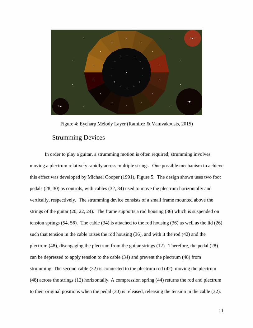
Figure 4: Eyeharp Melody Layer (Ramirez & Vamvakousis, 2015)
Strumming Devices
In order to play a guitar, a strumming motion is often required; strumming involves
moving a plectrum relatively rapidly across multiple strings. One possible mechanism to achieve
this effect was developed by Michael Cooper (1991), Figure 5. The design shown uses two foot
pedals (28, 30) as controls, with cables (32, 34) used to move the plectrum horizontally and
vertically, respectively. The strumming device consists of a small frame mounted above the
strings of the guitar (20, 22, 24). The frame supports a rod housing (36) which is suspended on
tension springs (54, 56). The cable (34) is attached to the rod housing (36) as well as the lid (26)
such that tension in the cable raises the rod housing (36), and with it the rod (42) and the
plectrum (48), disengaging the plectrum from the guitar strings (12). Therefore, the pedal (28)
can be depressed to apply tension to the cable (34) and prevent the plectrum (48) from
strumming. The second cable (32) is connected to the plectrum rod (42), moving the plectrum
(48) across the strings (12) horizontally. A compression spring (44) returns the rod and plectrum
to their original positions when the pedal (30) is released, releasing the tension in the cable (32).

12
If the rod housing (36) is in its lower position, this horizontal motion strums across the strings;
by modifying the speed the pedal is pressed with, the speed of the strum can be controlled, while
adjusting the distance the pedal is pushed allows strumming a subset of the strings. Disengaging
the plectrum from the strings by engaging the other pedal (28) allows the user to repeatedly
strum in the same direction without a reverse motion. To modify the device to operate on motor
control, the cables could be replaced by linear motors; in theory, the springs used in the patented
design could be used to reset the strummer when the motors were not active, so one-directional
solenoids could be used rather than linear servos, potentially reducing costs. Alternatively, the
cable system could be retained, with rotary motors to pull or release spools holding the cables.
This system has the benefit of simplicity, and with sufficient precision, could be used to pluck
single strings. The disadvantage of such a system is the complexity and precision needed; the
motor would need to move very specific distances and with very specific timing so as not to
strum unwanted strings.
Figure 5: Mechanical Guitar strummer (Cooper, 1991)

13
A similar concept was demonstrated by a team from Duke University (Lee, Leung, &
Topel, 2008), using a pair of linear solenoids to drive a plectrum across the strings of a guitar;
when the solenoid was activated, it drove the plectrum perpendicular to the strings, strumming
the guitar, while the second solenoid reversed the motion and reset the strummer, Figure 6. The
key innovation of this design was in the design of the strummer bar; rather than use a single
plectrum, the strummer had six, as shown in Figure 7. This allowed the device to effect a strum
with significantly less motion of the solenoid, allowing faster strumming with a slower driving
motion than other designs.
Figure 6: Strumming Device (Lee, Leung, & Topel, 2008)
14
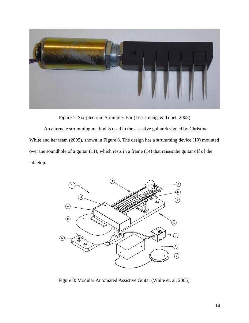
Figure 7: Six-plectrum Strummer Bar (Lee, Leung, & Topel, 2008)
An alternate strumming method is used in the assistive guitar designed by Christina
White and her team (2005), shown in Figure 8. The design has a strumming device (10) mounted
over the soundhole of a guitar (11), which rests in a frame (14) that raises the guitar off of the
tabletop.
Figure 8: Modular Automated Assistive Guitar (White et. al, 2005).
15
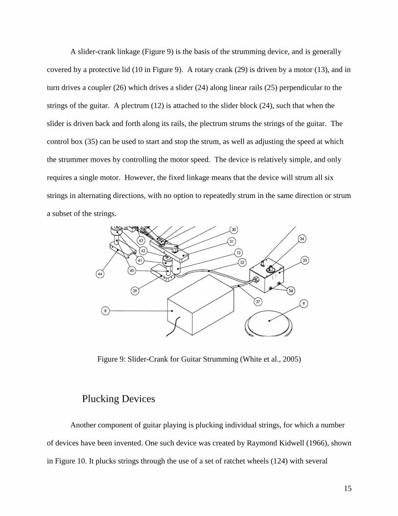
A slider-crank linkage (Figure 9) is the basis of the strumming device, and is generally
covered by a protective lid (10 in Figure 9). A rotary crank (29) is driven by a motor (13), and in
turn drives a coupler (26) which drives a slider (24) along linear rails (25) perpendicular to the
strings of the guitar. A plectrum (12) is attached to the slider block (24), such that when the
slider is driven back and forth along its rails, the plectrum strums the strings of the guitar. The
control box (35) can be used to start and stop the strum, as well as adjusting the speed at which
the strummer moves by controlling the motor speed. The device is relatively simple, and only
requires a single motor. However, the fixed linkage means that the device will strum all six
strings in alternating directions, with no option to repeatedly strum in the same direction or strum
a subset of the strings.
Figure 9: Slider-Crank for Guitar Strumming (White et al., 2005)
Plucking Devices
Another component of guitar playing is plucking individual strings, for which a number
of devices have been invented. One such device was created by Raymond Kidwell (1966), shown
in Figure 10. It plucks strings through the use of a set of ratchet wheels (124) with several

16
plectrums mounted to it, one wheel for each string to be played. Rotation of the wheel plucks the
string each time the plectrum engages with the strings. The ratchet pins (130) are engaged by a
pawl (206) attached to a sliding link (198), Figure 11. When the link (198) is driven to the left,
ratchet 206 engages with the pins (130) on wheel 126, plucking string E. When the link (198)
returns to the right, the pawl (206) slides underneath the pins, while pawl 208 presses the pins on
wheel 128 to pluck string G. The link (198) is driven by a series of intermediate links (184, 176)
that are ultimately driven by a foot pedal (166), such that the user can pluck the strings by
rocking his or her foot back and forth. Additionally, the individual plectrum wheels (126, 128),
are mounted on long shafts (146) which can be raised or lowered by a lever (114) which runs
beneath the body of the device and can be toggled by a foot pedal (108). By this method,
individual plectrums can be lowered to engage with the driving link, or raised to disengage them,
allowing the user to control which notes are played at any time. In a motorized version of the
mechanism, the driving link could be moving continuously, with a speed control to set tempo,
while the user chooses which plectrums to engage. However, this could result in notes being
delayed, if the plectrum wheel was engaged at the wrong time during the cycle, and causing
variable delays in response times that could reduce the user’s engagement with the music.
Figure 10: Mechanical Device for String Plucking (Kidwell, 1966)

17
Figure 11: Ratchet System for actuation of wheel-based plectrums (Kidwell, 1966)
Another ratchet-pawl plucker wheel system was designed by Andre DuPra (2013) and is
shown in Figure 12, using a simple linear solenoid to advance a ratchet wheel once for each
pulse of the solenoid. The striker (25), is brought into contact with the wheel (15) when the
solenoid extends, driving the wheel to rotate counterclockwise and pluck the string (10). The
spring on the striker (102) returns the striker to a downward position as the solenoid retracts,
allowing the wheel to rotate freely; however, the detent mechanism (30) prevents the wheel from
rotating past a single index, ensuring that each activation of the solenoid plucks exactly once.
This system allows for quick plucking. However, it is a highly complex system, with many
complex parts needed for each individual plucker, so implementation of the design could be
relatively expensive and difficult to repair.
Figure 12: Ratchet system driven by linear solenoid (DuPra, 2013)
A similar plucking system was designed by Kenneth and Jeffrey Caulkins (1998), using
wheels with plectrums attached; this system is shown in Figure 13. These wheels are driven by a
reversed crank-slider mechanism, with a linear motor driving a piston (124), which is pin-

18
connected to a coupler (128), which then causes the wheel (140) to rotate about a fixed shaft. In
order to ensure the wheel turns in the appropriate direction and stops after each pluck, a pair of
flat magnets (149) are located on opposite sides of an octagonal plate (130) attached to the
wheel; the magnets force the plate into positions where the magnets are closest together,
stopping the wheel in fixed positions when the mechanism is not being driven by the motor. The
primary disadvantage of this system is that the action of the motor is different for each pluck in a
single rotation of the wheel; at a certain point, slow forward motion will drive the wheel forward,
while in a different position, the same rotary speed will require a faster reverse motion, so
precise control of a bi-directional actuator is needed to control single plucks.
Figure 13: Apparatus for Strumming a Stringed Instrument (Caulkins & Caulkins, 1998)
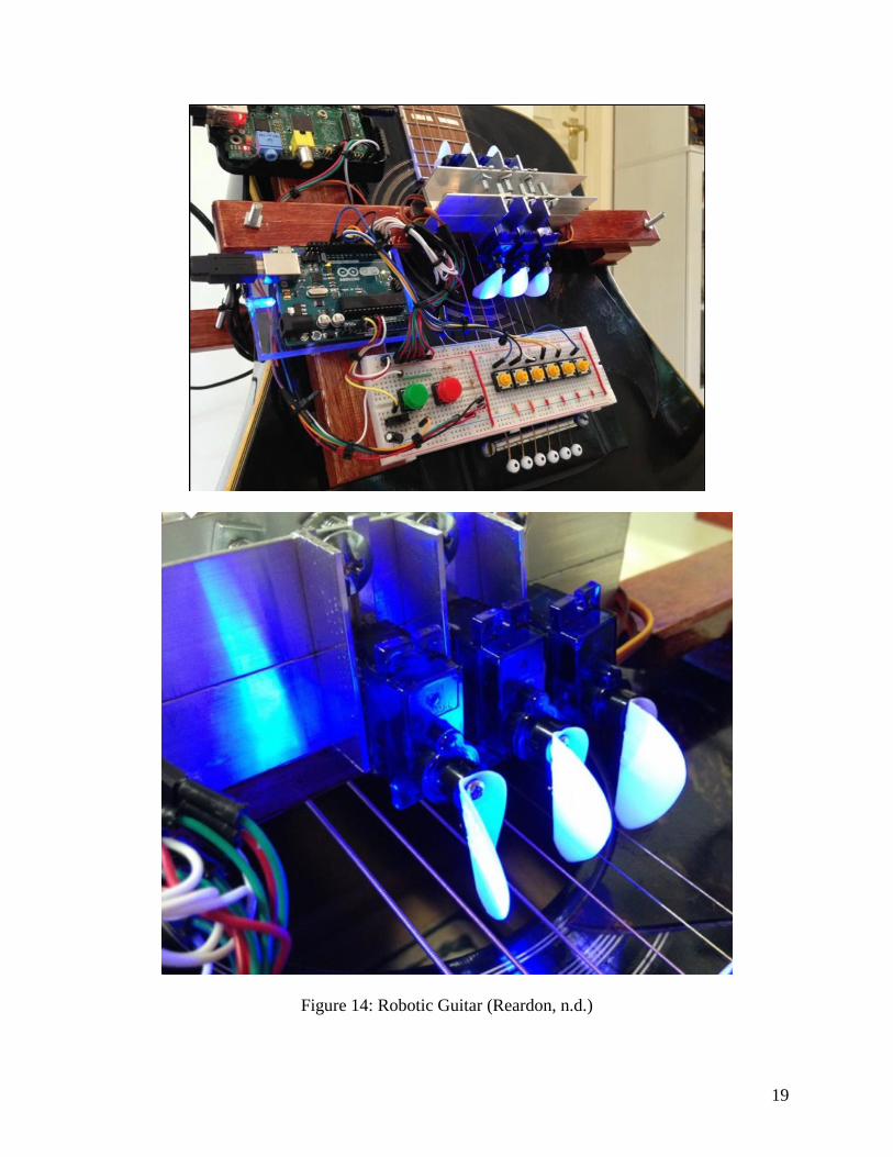
Another possible design was developed by Ben Reardon (Hobson, 2015), and uses a
rotary motor to actuate a plectrum for each string. The device can be seen in Figure 14. As the
motors are reversible, a small motion is all that is needed to pluck each string, and a second
pluck can be performed with an identical, reversed motion. This allows for fast, repeated
plucking. However, it does still require precise motor control, and the motors are mounted over
the soundhole of the guitar, which can muffle the sound.
19
Figure 14: Robotic Guitar (Reardon, n.d.)

20
As an alternative to machines designed to strum and pluck, several groups have
developed adaptive guitar picks. These picks are mounted on large, comfortable handles, or on a
glove or wrist brace, allowing a user with little control of their fingers to comfortably hold a
guitar pick (Day, 2018). The use of such a device would not help individuals with significant
spasticity in their arms, but for users who primarily have difficulty gripping the pick, such a
device could make playing the guitar significantly easier, especially when combined with a
device to assist the fretting.
21
Project Approach
Goal Statement
We will make an assistive playing device that helps people without the physical ability to
play a guitar. This will include both strumming and plucking so that the user would be able to
play a variety of songs that range in structure and notes. This device has the potential to enable
users who have never played music before to do so. As previously discussed, engagement with
music changes when people make music rather than listen to it. This deeper engagement with
music stimulates more of the brain and may lead to increased memory function.
User Requirements
Our designated user for this project is any person who does not have the physical
capabilities to play the guitar, specifically one who has limited manual dexterity and fine motor
skills. There are several assumptions made about potential users for this device. The first
assumption is that the user will have two control points on their body and will have the ability to
simultaneously move those points. Based on the needs of the user, the control sites will need a
range of motion between 12 cm along any axis, with precision of 2 cm in motion, or 240 cm
along any axis with precision of 40 cm. The second assumption is that the user will have the
ability to make repeatable gestures that will serve as the activation gestures for the sensor inputs.

22
Needs Assessment and Functional Specifications
Needs Assessment
For this assistive device to be an effective solution, there are many elements of the
problem that must be understood.
There are several requirements for the end device for it to be a successful solution: (1) it
must be affordable and repairable, (2) it must have a modular user interface, (3) the user must
feel like they are actively playing music, not watching a machine do so.
Affordability and minimal maintenance are essential to the continued use of assistive
devices. The sponsor of this project has a limited budget for the device, and should other
organizations reproduce the device for their clients, it must be made from commercially
available, inexpensive parts. Assistive technology users and their caretakers often do not have
deep technical backgrounds, so it is common that when an assistive device breaks, it is
abandoned (Hoffman & Ault, 1996). To reduce the likelihood of abandonment, the device must
be easy to fix and reassemble.
The modular user interface is a must for the device so that a variety of users can use the
device. Disabilities are highly specific to the individual, and therefore, some user interfaces may
work for certain individuals but not others. To give the device the widest possible user base, a
variety of user interfaces with different kinds of sensors must be interchangeable and still work
with the device. Inputs for control of fretting, note to pluck, and speed of plucking will be
required to play the guitar. A user would need to simultaneously trigger inputs when plucking
multiple strings at a time or changing the fretting while plucking. The team assumes that the user
will be able to have the ability to control at least two inputs at a time.

23
Finally, for the device to be truly successful, the user must have the feeling that they are
playing the music. The device loses its purpose of helping individuals play the guitar if it is
overly automated, sounds artificial, or visually hides the plucking and fretting of the strings.
When the user feels as if they are watching a machine instead of playing the guitar, they lose the
benefits that come with the deeper engagement with music.
Functional Specifications
Device
Operation
The device must be able to pluck two guitar strings simultaneously, so that a wide variety
of songs can be played. The device must also be able to pluck a new combination of notes every
eighth of a second, so that it can play 32nd notes at 60 beats per minute; this allows the user to
play at a relatively high tempo without the device falling behind. The device should be able to
produce a strum effect across the full set of six strings, as well as across a subset of the strings,
such as the lower three strings. This effect should be able to strum in either direction, so that
strums both up and down a scale can be played.
When plucking a string, the device should not displace a string more than 3.175 mm
parallel to the guitar body, and no more than 2 mm perpendicular to the guitar body, so that
strings do not interfere with each other or the body of the guitar during operation. Notes played
by the device should have at least 80% of the volume of notes played without the device present,
assuming otherwise identical actions.
24
Frame
The frame of this device must not prevent resonance in the body of the guitar. This would
dampen the sound produced. Aspects of maintaining resonance include not covering the
soundhole of the guitar, not altering the actual structure of the guitar, and not interfering with the
vibration of the guitar’s soundboard. Additionally, the frame of the guitar should be able to stand
upright without assistance while the guitar is being used. This allows the guitar to be stored
vertically with the device attached and allows the user to choose whether to have the guitar laid
horizontally or standing vertically while playing. The frame and device should have a mass of
less than 2 kilograms so that the guitar remains easily transportable. The device should make no
permanent alterations to the guitar, so that the guitar can be played manually with the device
removed. Attaching or removing the device from a guitar should require less than 10 minutes
and be achievable by hand, to allow easy setup on a new guitar. Additionally, the frame should
be able to fit on guitars ranging in width from 12 inches to 17 inches, with box heights ranging
from 17 inches to 21 inches, and depths between 3.5 and 5 inches. This ensures the device can
be fitted to a wide range of guitars, allowing users to adapt the device to existing instruments.
Forces on Guitar String
In previous iterations of this project the maximum distance the strings could be plucked
without creating interference was measured. This project team also measured the force necessary
to displace the low-E string, 3.383 N, and the high-E string, 2.396 N, to this distance (Dube et
al., 2018).

25
User Interface
Control Requirements
The user interface should never require using more than two control sites simultaneously,
meaning the device can be operated using only two limbs or other suitable control sites. The
control sites used should be analog, based on the user’s movements. These specifications allow
individuals without precise control of their fingers to use the device, allowing users with a wide
variety of impairments to use the device.
Response Time
There is a slight delay after a signal is input and when the corresponding response is
produced. This time between input and output is known as latency and should be no longer than
10ms. Having a short latency is important to give a feeling of full control. The time limit of 10ms
is based on research that shows the latency is noticeable at different speeds for different sounds,
with the maximum to be normally noticeable for a guitar being 12ms. Walker (2005) explains,
“the speed of sound in air is roughly a thousand feet per second, each millisecond of delay is
equivalent to listening to the sound from a point one foot further away,” meaning that a 10ms
latency is roughly equivalent to listening to a guitar from 10 feet away.
Setup and Calibration
The user interface should not require a technical background to be set up and prepared for
use. Setup should not take someone longer than 10 minutes, and the sensors must be in an
operable state no longer than 2 minutes after being turned on.

26
Manufacturing of Devices
The plucking device should use at least 90% commercially available parts, by count; this
makes it easier to replace damaged parts and reduces overall costs, as well as allowing faster
delivery of replacement parts. Custom components should be manufactured using methods and
materials that are available to the general public at low cost, such as 3-D printed plastic or laser-
cut acrylic.
The user interface should implement easily obtainable and affordable sensors that can be
easily replaced should they be damaged or broken. Additional parts, such as baseplates, stands,
frames, housing, etc., should come from readily available materials that can also be easily
replaced.
Both the plucking device and user interface should be easily assembled and repaired by a
user with basic tools, specifically basic screwdrivers, hammers, and wrenches. Documentation
should be provided in plain English so that users understand how the device works to aid
assembly, troubleshooting, and repair. These requirements ensure that the users of the device can
build and repair the device affordably, allowing wider use over longer periods of time.
Electronics
The device should be powered by batteries that can either be easily obtained by the user for
replacement or are rechargeable. To not cause damage on the microcontroller, the current drawn
at any time should not exceed the maximum of the board’s pins. Components should be easily
traceable throughout the circuitry so that they may be replaced without an in-depth
understanding of the whole circuit. The circuit should be packaged such that there is no risk of
accidental unplugging.

27
Cost
The final cost of the plucking device and user interface should not exceed $250. The parts
should be easy to replace if broken; however, the devices should not require consumable
components that would produce a continuing cost.

28
Plucker Designs
Preliminary Designs
Eight preliminary plucking mechanisms were considered for the device: a revolving
platform with guitar picks on levers, rotating plectrum wheels, four-bar crank-rocker linkages,
four-bar double-rocker linkages, four-bar crank-slider linkages, linearly actuated plectrums,
robotic arms, and a harpsichord plectrum assembly. Each of these designs are discussed further
in Appendix B.
Initial Decision Matrix
Each design was rated on each of the criteria, which were weighted from 1 to 5; the
scores were totaled for comparison and are shown in Table 1. The rating scales and full
descriptions of each criteria can be found in Appendix C.
29
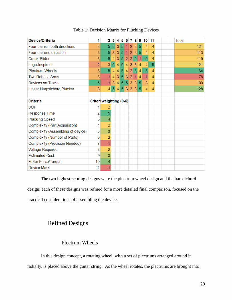
Table 1: Decision Matrix for Plucking Devices
The two highest-scoring designs were the plectrum wheel design and the harpsichord
design; each of these designs was refined for a more detailed final comparison, focused on the
practical considerations of assembling the device.
Refined Designs
Plectrum Wheels
In this design concept, a rotating wheel, with a set of plectrums arranged around it
radially, is placed above the guitar string. As the wheel rotates, the plectrums are brought into

30
contact with the string, displacing it and performing a pluck. The rotation angle is controlled to
ensure the string is plucked exactly once each time a particular plucker is activated; one plucker
is located above each string of the guitar, for a total of six pluckers. The most critical constraint
on the design of the plucking device is the space between the strings; the strings are
approximately 10 mm apart, so by staggering the plucking devices in two rows, each plucker can
have a maximum width of 20 mm. This limits the size of the plectrum wheel, as well as the size
of motor available. The other constraint on the motor selection is the vertical distance above the
string, to ensure the motor does not collide with the string at any point during the motion of the
plectrum. To ensure adequate space between the motor and the guitar strings, a 2:1 gear ratio
was used, increasing the speed of the wheel and offsetting the motor from the strings. This
increases the effective speed of the pluck, allowing a faster response to the trigger. However, it
also reduces the torque available at the wheel. The wheel has three plectrums arranged radially.
Based on the maximum required plucking force of 3.4 N (Dube, et. al., 2018), and the available
torque from the motor, the greatest wheel radius allowable is 22 mm. However, due to the space
requirement, the radius is limited to 10 mm; this allows the plucking devices to be placed in two
staggered rows, minimizing the distance between plectrums in the direction of the strings.
Minimizing this spacing produces a more consistent sound, replicating the plucking pattern of a
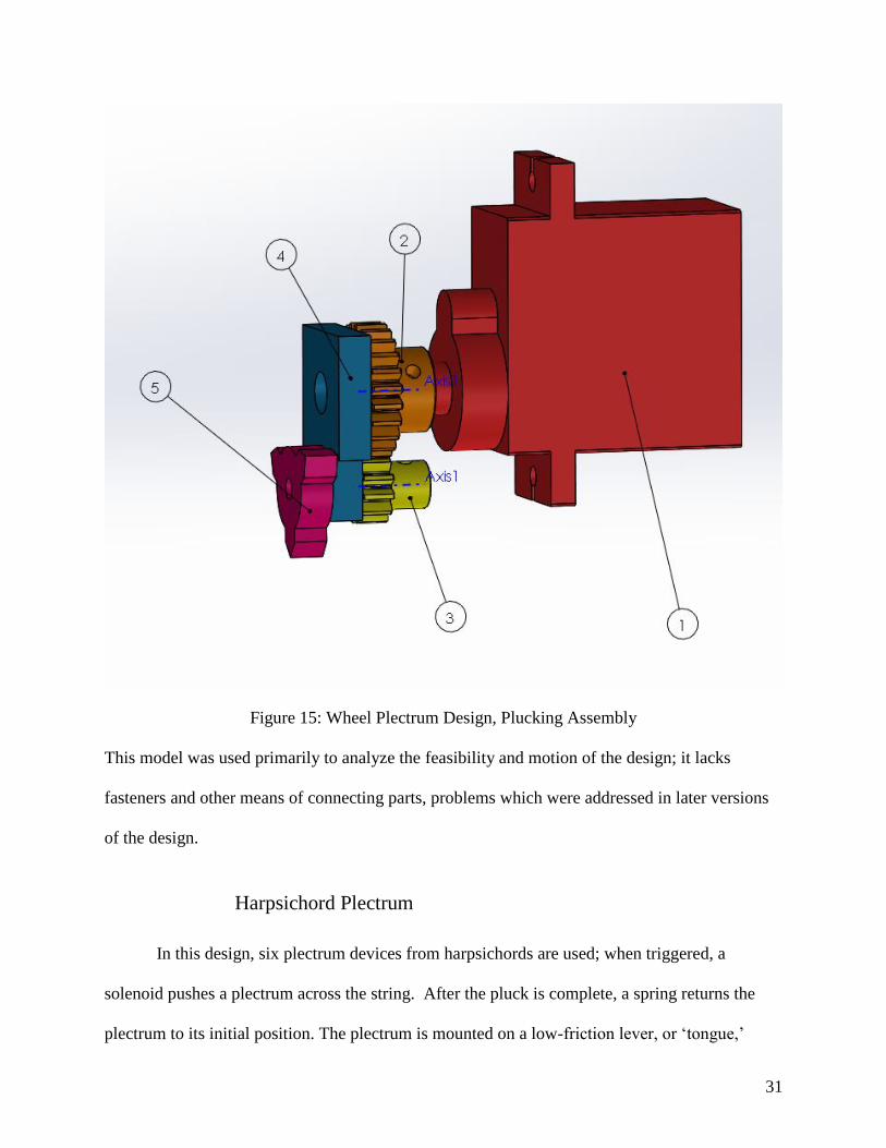
typical player. A 3D model of the plectrum assembly is shown as Figure 15. The motor (1)
drives a 12 mm gear (2); this gear meshes with a 6 mm gear (3), which drives the plectrum (5).
A small frame (4) holds the shafts in place, and rests on a horizontal surface along with the
motor.
31
Figure 15: Wheel Plectrum Design, Plucking Assembly
This model was used primarily to analyze the feasibility and motion of the design; it lacks
fasteners and other means of connecting parts, problems which were addressed in later versions
of the design.
Harpsichord Plectrum
In this design, six plectrum devices from harpsichords are used; when triggered, a
solenoid pushes a plectrum across the string. After the pluck is complete, a spring returns the
plectrum to its initial position. The plectrum is mounted on a low-friction lever, or ‘tongue,’
32
which allows the plectrum to slip around the string on the return stroke, rather than plucking a
second time. Additionally, a damping pad is brought into contact with the string at the end of the
stroke to quiet the vibrations still introduced by the plectrum. In this design, the plectrum jacks
would be perpendicular to the strings, and parallel to the body of the guitar.
Based on the distance between strings and the force requirements a Small Push-Pull
Solenoid (Adafruit, n.d.) was chosen for actuation. This solenoid has a width of 22 mm allowing
a single row to actuate all the harpsichord jacks. It also provides a throw distance of 5.5 mm and
a 5 N starting force, which is enough force and distance to pluck a single string without over
traveling and hitting the next string. As the solenoid is spring-loaded, a single activation plucks
the string once and returns the plectrum to its starting position.
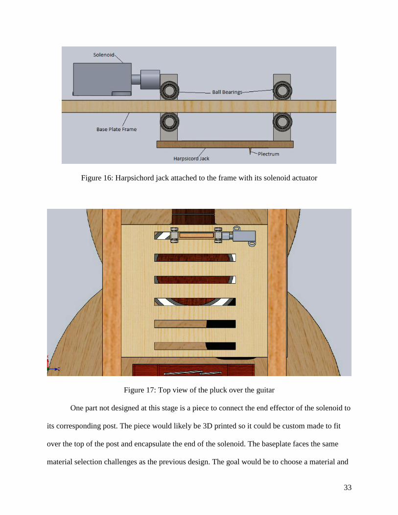
In this design the face of the harpsichord jacks needed to be lying parallel to the face of
the guitar, no more than ⅛” away from the strings. The jack must also be able to travel smoothly
in a linear direction. This smooth linear travel was achieved by designing slots in the supporting
frame that would have two square posts through them, attached to the ends of the jack. These
posts each have two sets of ball bearing rollers, one on each side of the frame, which keep the
jack from moving up and down but allow for horizontal motion across the strings as shown in
Figures 16 and 17.
33
Figure 16: Harpsichord jack attached to the frame with its solenoid actuator
Figure 17: Top view of the pluck over the guitar
One part not designed at this stage is a piece to connect the end effector of the solenoid to
its corresponding post. The piece would likely be 3D printed so it could be custom made to fit
over the top of the post and encapsulate the end of the solenoid. The baseplate faces the same
material selection challenges as the previous design. The goal would be to choose a material and

34
design which would hold up against user induced forces and still allow enough sound to pass
through to minimize the effect on the sound quality of the guitar.
Final Decision Matrix
After considering both designs in depth a second decision matrix was created with new
criteria. The updated criteria are shown in bold below and are fully described in Appendix D.
The results are summarized below in Table 2; as shown, the plectrum wheel design scores
significantly higher than the harpsichord design.
Table 2: Final Decision Matrix (bolded criteria have been re-evaluated)
Based on the updated decision matrix and the further evaluation of the two final designs
the plectrum wheel design was chosen for this project. This design scored very highly on
response time, number of parts, required voltage and the motor torque. It also performed much
better in the categories in which the harpsichord plucker was weak, such as the difficulty of part
acquisition, the number of parts and the mass of the device. With the plucker design chosen the

35
next steps required were completing the design of the frame, finalizing the details of the plucker
mechanism, and developing a working prototype.
Developed Design
Plucking Device
Further refinements of the rotating plectrum design were made to account for the
limitations of the geometry, include necessary fasteners, and allow the user to adjust the device
to fit multiple guitars with different dimensions. Rather than positioning the baseplate under the
motor, the baseplate is above the plectrum device, and 3d-printed frames hold the motor and
shafts in position, as shown in Figure 18.
Figure 18: Baseplate Above the Plectra
M1.6 mm screws hold the motor to its frame as well as connecting the frame elements to
the baseplate. The screws fit into slots on the baseplate rather than holes, allowing the plucking
device to be moved horizontally by loosening the screws and sliding the device into position
above the relevant string.
The plectrum itself was also redesigned; a larger angle at the tip was used, as well as a
rounded blade to allow the plectrum to have a shorter period of contact with the string, allowing

36
a faster response time. Additionally, the plectrum was redesigned for unidirectional rotation,
reducing the excess material and preventing the string from colliding with the plectrum after it
releases. A dynamic model of the plectrum was designed to determine the optimal geometry
using Creo Parametric software. Based on those tests, a tip angle of 30 degrees results in the
string failing to release from the plectrum; overall, as plectrum angle increases, the plectrum
strikes the string earlier in its rotation, but also releases it earlier; an angle that is too small
prevents proper plucking, while an angle too large results in an oversized plectrum and a poor
response time. An angle of 50 degrees was used for the prototype.
The lower shaft was incorporated into the plectrum part, which was 3D printed, reducing
the need for fasteners. The upper shaft slides over the servo armature included with the motor
and is glued in place; that armature is driven by a spline connection and secured to the motor
shaft with a coaxial set screw. The gears are held to the shafts by radial set screws, and washers
are used to provide spacing between the gears and the shaft housing. The full plucker assembly is
shown in Figure 19.

37
Figure 19: Prototype Design of Plucker Assembly

38
Table 3: Plucker Assembly Components
Component Number Component Name
1 Servo Motor
2 12mm Gear
3 Gearshaft Mounting
4 6mm gear
5 Rotating Plectrum
6 M4 washer
7 M2 washer
8 Motor Frame
9 M1.6 socket head
screw
10 M1.6 hex nut
11 Upper Gearshaft
Frame
In order to support the plucker on top of the guitar a frame was designed. This frame was
a modified version of the frame used by a previous project team (Dube, et. al., 2018). It was
designed to allow for a guitar to be held underneath the plucker without affecting the quality of
the sound; to do this, the guitar is held in place without the frame contacting the front or back of
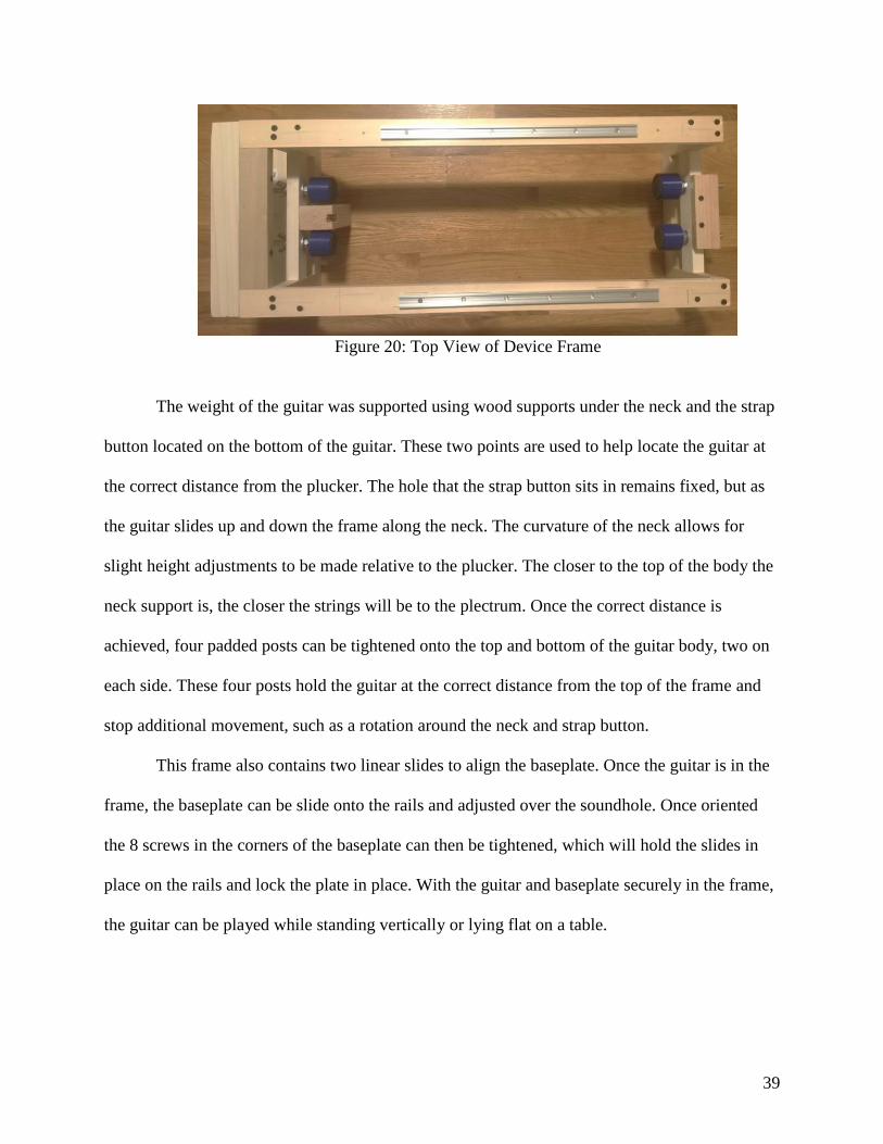
the body. The completed frame is pictured in Figure 20.
39
Figure 20: Top View of Device Frame
The weight of the guitar was supported using wood supports under the neck and the strap
button located on the bottom of the guitar. These two points are used to help locate the guitar at
the correct distance from the plucker. The hole that the strap button sits in remains fixed, but as
the guitar slides up and down the frame along the neck. The curvature of the neck allows for
slight height adjustments to be made relative to the plucker. The closer to the top of the body the
neck support is, the closer the strings will be to the plectrum. Once the correct distance is
achieved, four padded posts can be tightened onto the top and bottom of the guitar body, two on
each side. These four posts hold the guitar at the correct distance from the top of the frame and
stop additional movement, such as a rotation around the neck and strap button.
This frame also contains two linear slides to align the baseplate. Once the guitar is in the
frame, the baseplate can be slide onto the rails and adjusted over the soundhole. Once oriented
the 8 screws in the corners of the baseplate can then be tightened, which will hold the slides in
place on the rails and lock the plate in place. With the guitar and baseplate securely in the frame,
the guitar can be played while standing vertically or lying flat on a table.

40
User Interface Designs
Preliminary Designs
Several preliminary designs were discussed, with sensors such as a camera, inertial
measurement unit, IR range sensor, PIR motion detector, ZX gesture sensor, button, switch, and
a spectral sensor. For the camera system, vision tracking would be used to see where the user
moved within the frame. For the inertial measurement unit design, the sensor would be mounted
to the user, and their position tracked. For the spectral sensor design, colored cards would be
used to indicate which string to pluck. For the remaining sensors, six sensors, each representing a
string, would be mounted such that the user could trigger the input either by motion or tactilely.
All of these designs are discussed further in Appendix E.
Initial Decision Matrix
The aforementioned preliminary designs were compared using a decision matrix. In our
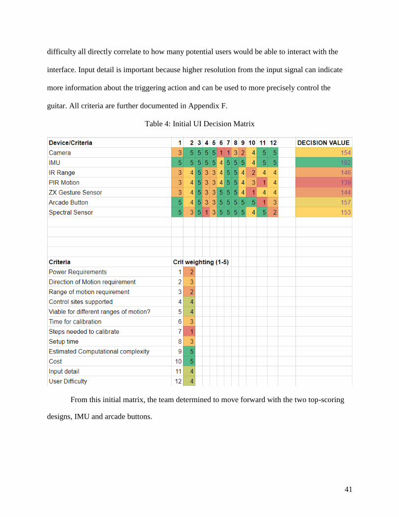
decision matrix, Table 4 below, manufacturability and user accessibility were highly prioritized.
Weights from 1 to 5 were given to each criterion, where 5 is the most important and 1 is the least
important. Cost and estimated computational complexity were weighted 5. High costs deter
anyone who is trying to replicate or repair the interface. Computational complexity influences
how much delay between the interface triggering and the guitar plucking and gives insight to the
complexity of the required code. Complex algorithms should be avoided if possible, such that
anyone who is working with the interface is able to understand how it functions without
extensive study. The criteria that were given weights of 4 were: control sites supported, viability
for different ranges of motion, input detail, and user difficulty. Control sites, viability, and
41
difficulty all directly correlate to how many potential users would be able to interact with the
interface. Input detail is important because higher resolution from the input signal can indicate
more information about the triggering action and can be used to more precisely control the
guitar. All criteria are further documented in Appendix F.
Table 4: Initial UI Decision Matrix
From this initial matrix, the team determined to move forward with the two top-scoring
designs, IMU and arcade buttons.

42
Refined Designs
Buttons
For the button design, two button options were reviewed: the 60mm Buddy Button and
100mm arcade button. The Buddy Button is a commercial product sold by Ablenet. It is a low
force push button that requires only 142 gf to activate. It is attached to a 5ft cord with a 3.5mm
mono plug to interface to other electronics (Ablenet, n.d.). Shown in Figure 21, the Buddy
Buttons are wired to an Arduino and can arranged in any shape for the user’s ease.
Figure 21: Buddy Button Arrangement (Higham, 2018)
The one limitation the Buddy Button presents is the cost. Six buttons are needed, and at a
cost of $65 each, the total cost of the interface would be around $400. The benefit of the Buddy
Button’s low force does not outweigh the high cost because the focus of the project is on users
who would be able to exert a typical amount of force to push a button.
One hundred mm arcade buttons are sold from various vendors at much lower cost. The
arcade button is composed of two parts, a 100 mm dome, and underneath a microswitch. The
microswitch protrudes 50 mm below the base of the button, due to this construction, the buttons

43
must be placed in frame or box such that it is elevated from the surface. An initial option for this
is presented in Figure 22.
Figure 22: Arcade Button Arrangement
Upon further review, having all six buttons spaced linearly apart would separate the
furthest buttons by almost 1m. An updated design that houses each button separately is presented
in Figure 23. Six boxes would be laser cut out of 0.25” material. The boxes then could be
arranged in whatever shape benefits the user’s range of motion.
Figure 23: Arcade Button Box

44
There are several ways that the buttons can be wired to the Arduino UNO. This
microcontroller was chosen both because it was used in the previous iteration of this project and
because the project sponsor uses it for his other assistive technologies. The Arduino UNO has a
total of thirteen digital input/output pins, six of which can be used for Pulse Width Modulation
(PWM) and should be reserved for running actuators for the plucker mechanism. To read all six
button values with the fewest pins, resistors can be put in parallel with the buttons and the
voltage can be read through one of the five analog pins. By comparing the input to what is the
known value of analog voltages per resistor, the pressed button or buttons can be calculated. The
following figure is a circuit from the Arduino Forums on how buttons can be wired in parallel.
Figure 24: Parallel Button Circuit (digimike, 2010)
To test, one 100 mm arcade button and one momentary push button were used, as shown
in Figure 25.

45
Figure 25: Button Testbench
Five percent precision resistor values (measured in ohms) that worked are presented in
the following chart that shows the analog value for each pair of resistor values.
Table 5: Analog Values for Resistor Combination Chart
Resistor 0 2.2k 4.7k 8.2k 10k 12k 18k
0 0 836-837 692-694 558-560 509-511 460-461 362-363
2.2k 836-837 X 885-894 869-871 865-867 860-862 849-857
4.7k 692-694 885-894 X 785-787 773-774 762-764 741-743
8.2k 558-560 869-871 785-787 X 702-704 684-686 648-653
10k 509-511 865-867 773-774 702-704 X 659-660 619-622
12k 460-461 860-862 762-764 684-686 659-660 X 591-594
18k 362-363 849-857 741-743 648-653 619-622 591-594 X
Although 5% precision resistors were used for testing, they should not be used for the
final user interface as the possible resistor variance leads to total resistances that could be

46
mistaken as two different combinations. There are also only twenty-four values of 5% resistors
while 1% resistors offer a greater selection of ninety-six.
Inertial Measurement Unit
While the primary concern with the Inertial Measurement Unit (IMU) implementation is
the computational complexity and accumulating errors, there are also design decisions to be
made about how the system would be structured. The team compared two designs, the primary
difference between these being the microcontroller board used.
Both designs will use the Sparkfun MPU-9250 IMU breakout board. The InvenSense
MPU-9250 is a well-regarded standard for 9 degree of freedom motion tracking. Compared to
competitors this device is more accurate, smaller, and cheaper. Additionally, the Sparkfun
breakout board is well documented and has been thoroughly tested in conjunction with Arduino
boards. In both designs the IMU will be communicating using an Inter-integrated Circuit (I2C)
serial computer bus. This communication requires only two pins and can be used to
communicate with many devices at once. The Sparkfun breakout board only allows for two
device addresses but this can be extended using additional hardware if necessary. In both designs
the Arduino microcontroller board will serve as the Master node, providing clock signal and
initiating communication, and the IMU will serve as the Slave node, receiving the clock signal
and responding to the master. In addition to a 3.3V power and ground this requires the SCL
(clock) and SDA (data) pins on the Arduino. These pins are determined by the hardware.
The first design would be to use a stationary Arduino UNO with tethered connections to a
logic level converter and then the Sparkfun MPU-9250. The IMU is a 3.3V device and the
Arduino UNO has an operating voltage of 5V so the logic level converter is necessary to allow
the I2C to be properly interpreted. Alternatively, this can be accomplished using external 4.7K

47
pull up resistors on the SCL and SDA pin. Since I2C communication already utilizes built in pull
up resistors, these would be acting to reduce the voltage so that the IMU could interpret the clock
and data sent from the Master node. This method is problematic primarily due to instability and
should only be considered as a temporary solution. The logic level converter provides a
permanent solution but introduces more complexity in the electronics.
The second design would involve using two Arduino Pro Mini 328 - 3.3V/8MHz boards
with attached IMUs and wireless communication modules. The Arduino Pro Mini is a 3.3V
board so no intermediate hardware is necessary to communicate with the IMU. The Pro Mini is
also a much smaller board than the UNO so the whole device could be mounted directly on the
control site. This gives the option to use wireless communication via nRF24L01+ transceiver
module. Wireless communication provides the clear advantage of not risking cords becoming
unplugged, tangled, or impacting the motion of the control site. The communication speed would
need to be determined experimentally but similar projects have shown the response time to be
sufficient. The Arduino Pro Mini does not come with USB for programming so this would have
to be done via an additional component.
From a cost perspective the designs are nearly equivalent. The Arduino UNO costs
around $20 and the Arduino Pro Mini costs $9, but two are needed so the costs are equivalent.
The WiFi transceiver modules can be purchased at the rate of 10 for $12. The logic converter can
be purchased for only $3 and only two would be needed.
Ultimately the decision was made to pursue the use of Arduino Pro Mini. The advantages
of this design are that it can communicate with the IMU without intermediate hardware, is small
enough to be mounted on the control site, and still provides comparable computational power.

48
Final Decision Matrix
After considering the IMU and button-based UI approaches in detail an updated decision
matrix was constructed. The criteria listed from the previous matrix have been used to reevaluate
the IMU and Button user interfaces for the final decision matrix in Table 6. The new scores were
given based on both testing with the components and personal conversations with an
occupational therapist. Criteria shown in bold have been re-evaluated and are fully described in
Appendix G.
Table 6: Final Decision Matrix (bolded criteria have been re-evaluated)
49
Developed Design
Electronic Component Selection
To implement the IMU-based user interface, the following components are needed: three
Arduinos, three wireless transceivers, two IMUs, one RGB LED, one momentary push button,
and batteries. The components are used for three separate devices: two identical wearables and
one device mounted to the guitar.
The wearable devices used the 3.3V Arduino Pro Mini 328, for its small size of 18 by 33
mm and same 3.3V logic level as the MPU-9250 IMU. The guitar device used the Arduino
UNO, which was saved from the previous project iteration. The UNO provides a sufficient
number of digital I/O pins and has a small-enough footprint that it can be easily mounted to the
same base plate as the plucking device. The wireless transceivers that have been selected for the
project are the nRF24L01+ Single Chip Transceiver. The nRF24L01+ communicates to the
Arduinos via Serial Peripheral Interface (SPI) and features bidirectional communication up to 2
Megabits per second (Nordic Semiconductor, 2008). Furthermore, this device can be used to
develop a network of up to 3125 devices communicating over a single channel, each module
actively listening to six other modules at a time (How to Mechatronics, n.d.) so this application is
well within the communication limits of the chip.
The goal for powering the devices was to use batteries that enable all the devices to be
portable as well as provide several hours of use between charges. For the wearable devices, the
total current draw was estimated to be about 50mA; the Arduino Pro Mini draws 30mA, the IMU
draws 5mA, and the nRF24L01+ draws 15mA. The selected battery is a 3.7V 400mAh Lithium
Ion battery that will supply about 8 hours of continuous use between charges. For the guitar
50
device, the overall current draw was estimated to be 400mA. The Arduino UNO draws 45mA,
and the RGB LED draws 20mA.
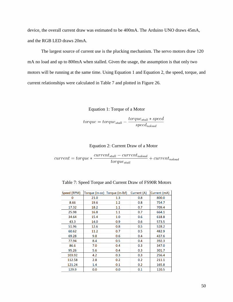
The largest source of current use is the plucking mechanism. The servo motors draw 120
mA no load and up to 800mA when stalled. Given the usage, the assumption is that only two
motors will be running at the same time. Using Equation 1 and Equation 2, the speed, torque, and
current relationships were calculated in Table 7 and plotted in Figure 26.
Equation 1: Torque of a Motor
Equation 2: Current Draw of a Motor
Table 7: Speed Torque and Current Draw of FS90R Motors

51
Figure 26: Speed and Current vs. Torque of FS90R Motors
Based on SolidWorks test results, the estimated torque to the motor during a pluck is 1.4
in-oz and would result in 165mA current draw. Given the total estimation of 400mA, two 3.7V
1Ah batteries were selected. Two batteries were needed to get 7.4V in series to be within the
Arduino UNO’s voltage requirement.
Circuit Design
To eliminate the end user having to solder any electrical components, printed circuit
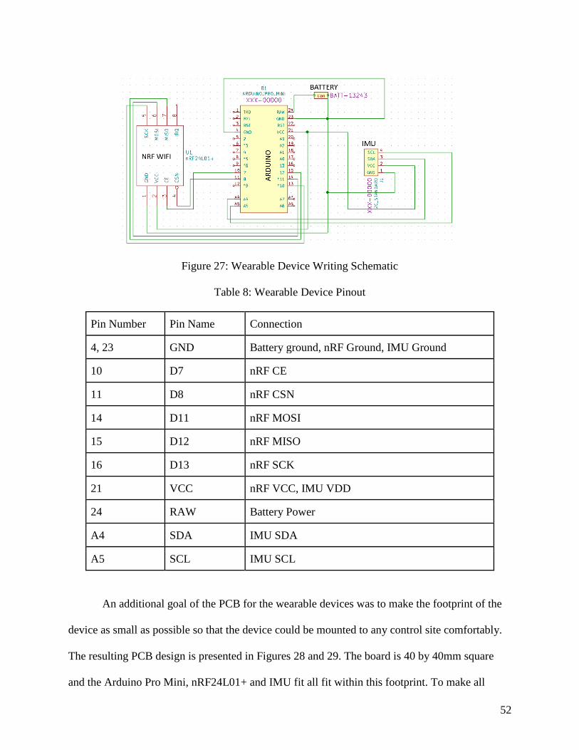
boards (PCBs) were designed for both the wearable devices and the guitar device. The schematic
for the wearable device board is presented in Figure 27. Table 8 presents the pinout of the
design.
52
Figure 27: Wearable Device Writing Schematic
Table 8: Wearable Device Pinout
Pin Number Pin Name Connection
4, 23 GND Battery ground, nRF Ground, IMU Ground
10 D7 nRF CE
11 D8 nRF CSN
14 D11 nRF MOSI
15 D12 nRF MISO
16 D13 nRF SCK
21 VCC nRF VCC, IMU VDD
24 RAW Battery Power
A4 SDA IMU SDA
A5 SCL IMU SCL
An additional goal of the PCB for the wearable devices was to make the footprint of the
device as small as possible so that the device could be mounted to any control site comfortably.
The resulting PCB design is presented in Figures 28 and 29. The board is 40 by 40mm square
and the Arduino Pro Mini, nRF24L01+ and IMU fit all fit within this footprint. To make all

53
components fit, the nRF and IMU are mounted on the top of the PCB, and the Arduino and
battery connector are mounted to the bottom of the PCB. To accomodate all of the required
connections, it is a multilayer design; the red traces are the top copper layer, and the green traces
are the bottom copper layer.
Figure 28: Top View Wearable PCB Design

54
Figure 29: Bottom View Wearable PCB Design
The guitar device wiring schematic is presented in Figure 30. Table 9 presents the pinout of the
design.
Figure 30: Guitar Device Writing Schematic

55
Table 9: Guitar Device Pinout
Pin Number Pin Name Connection
15 D0/RX Button
16 D1/TX Servo 1 Input
17 D2 Servo 2 Input
18 D3 Servo 3 Input
19 D4 Servo 4 Input
20 D5 Servo 5 Input
21 D6 Servo 6 Input
22 D7 nRF CE
23 D8 nRF CSN
24 D9 LED DIN
26 D11 nRF MOSI
27 D12 nRF MISO
28 D13 nRF SCK
8 VIN Battery Power, Servo VCC
4 3V3 nRF VCC
5 +5V Button, RGB LED
6, 7, 29 GND Battery Ground, Ground of all components
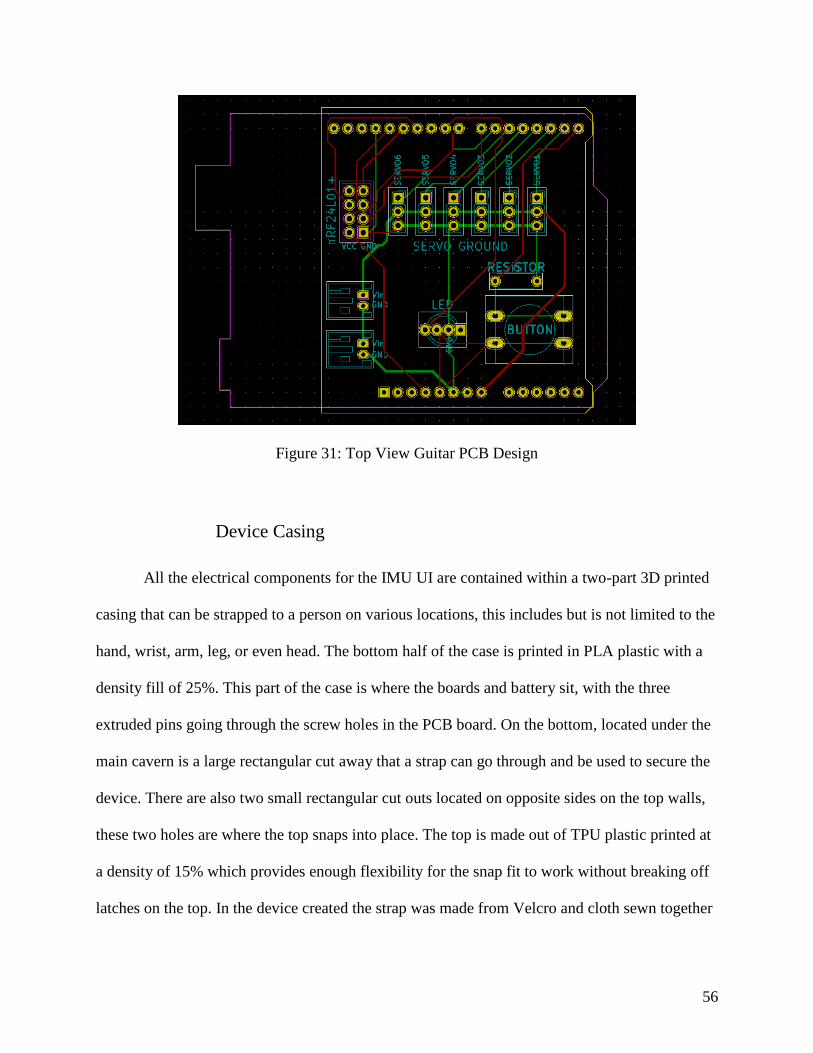
The guitar device PCB was designed to fit over the top of the Arduino UNO with all of
the components mounted to the top. Just like the other PCB, the red traces are the top copper
layer, and the green traces are the bottom copper layer. The PCB layout is shown in Figure 31.
56
Figure 31: Top View Guitar PCB Design
Device Casing
All the electrical components for the IMU UI are contained within a two-part 3D printed
casing that can be strapped to a person on various locations, this includes but is not limited to the
hand, wrist, arm, leg, or even head. The bottom half of the case is printed in PLA plastic with a
density fill of 25%. This part of the case is where the boards and battery sit, with the three
extruded pins going through the screw holes in the PCB board. On the bottom, located under the
main cavern is a large rectangular cut away that a strap can go through and be used to secure the
device. There are also two small rectangular cut outs located on opposite sides on the top walls,
these two holes are where the top snaps into place. The top is made out of TPU plastic printed at
a density of 15% which provides enough flexibility for the snap fit to work without breaking off
latches on the top. In the device created the strap was made from Velcro and cloth sewn together

57
to provide a secure and easily adjustable fit, but it can be interchanged with anything that would
fit through the strap hole on the casing.
Figure 32: Pictures of Device Casing
Overall Code Design
The diagram below gives an outline of the electronic components of this system and
shows how these communicate. The components in the blue box are mounted on the user’s
control site and communicate via a wireless transceiver with the components in the red box,
which is mounted on the guitar. This diagram also labels communication protocols and the
information being communicated. The software development has been split into three
components:
1. Reading IMU sensor values with Arduino Pro Mini and generating string plucked
messages
2. Sending messages regarding string plucks via wireless transceiver
3. Use Arduino UNO on guitar body to control servo motion
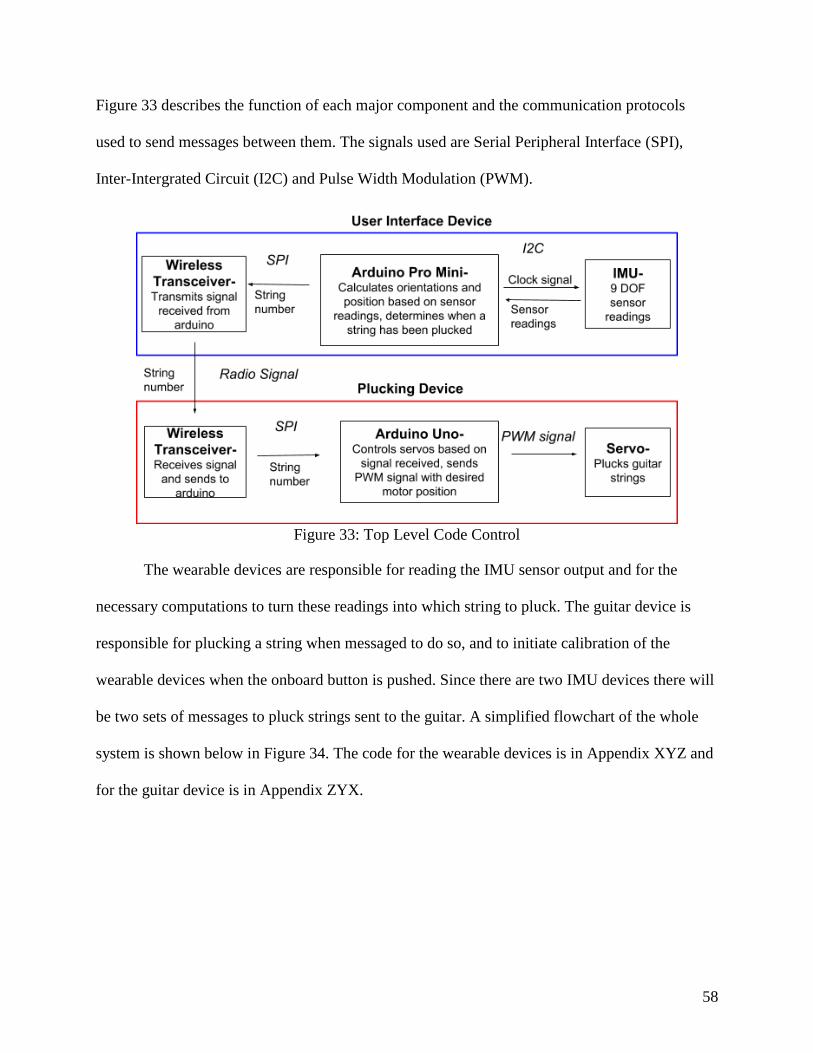
58
Figure 33 describes the function of each major component and the communication protocols
used to send messages between them. The signals used are Serial Peripheral Interface (SPI),
Inter-Intergrated Circuit (I2C) and Pulse Width Modulation (PWM).
Figure 33: Top Level Code Control
The wearable devices are responsible for reading the IMU sensor output and for the
necessary computations to turn these readings into which string to pluck. The guitar device is
responsible for plucking a string when messaged to do so, and to initiate calibration of the
wearable devices when the onboard button is pushed. Since there are two IMU devices there will
be two sets of messages to pluck strings sent to the guitar. A simplified flowchart of the whole
system is shown below in Figure 34. The code for the wearable devices is in Appendix XYZ and
for the guitar device is in Appendix ZYX.

59
Figure 34: Flow Chart of Whole Device Code
A calibration process is included in the system to allow for a wide range of users with
various ranges of motion to be able to use the device. The calibration process works through
communication between the IMU device and guitar device. The process is initiated by pressing a
button on the guitar device and then again for each subsequent phase of the calibration. A flow
chart of this process on both boards is shown below in Figure 35. The calibration sets parameters
to be used in determining when a pluck is registered.

60
Figure 35: Calibration Process in IMU and Guitar Devices
Wearable Device Code Design
The readings from the IMU give the measurements from the accelerometer, gyroscope,
and magnetometer along three axis each for a total of nine degrees of freedom. Using sensor
fusion, these readings are combined and filtered to give useable orientation values in the form of
Euler angles. This orientation data is used to determine when pluck messages should be
transmitted to the guitar. There are two wearable devices simultaneously transmitting to the
guitar to allow for the user to pluck multiple strings at once, a necessity for imitating normal
guitar play. A diagram of the wearable device process is shown below in Figure 36.

61
Figure 36: UI Arduino Flowchart
Tracking Orientation of Wearable Device
Instantaneous readings of each of the nine axis are taken roughly 147 times a second. The
raw readings provide information on the instantaneous motion of the IMU but needs to be
processed to be useful for orientation tracking. These are filtered using a Mahoney-Madgwick
filter which uses the acceleration due to gravity and the earth’s magnetic field to find the
device’s orientation in absolute space. Incrementally the sensor readings are applied based on the
previous readings and expected variance giving a robust estimate for the device’s orientation
expressed in quaternions. The Mahony-Madgwick filter implemented for this goal is a
sophisticated, lightweight algorithm that gives sensor fusion typical of a Kalman filter but in a
much more efficient manner. Importantly these calculations will be able to keep up with the
approximately 147 Hz sampling frequency of the IMU. This ensures the orientation will be
recent and there will not be error resulting from missing readings during computation.

62
There are two main components to the wearable device code structure, an interrupt that
takes readings from the IMU and a loop for processing the readings and calculating string pluck
signals. Before either of these components are used there are necessary setup functions that will
only be used once to initialize communication between the Arduino and IMU, and to calibrate
the IMU tolerances. Whenever all nine variables of the IMU have a new value a signal is sent to
the Arduino; when this is received an interrupt is triggered and code that reads the IMU and
stores the values is called. The rest of the code runs in a loop that processes the IMU readings
using the Mahoney-Madgwick filter to update the quaternions.
Euler angles and quaternions are two methods of representing the orientation of a body.
Each has their own advantages and disadvantages and work in significantly different ways.
Quaternions use complex numbers to represent a rotation theta around a fixed axis known as the
Euler axis. Euler angles use pitch, roll and yaw to represent a rotation. Euler angles have some
inherent disadvantages for tracking orientation but are better for intuitive understanding of
orientation information. In this application the orientation is tracked in quaternions and
converted to Euler angles only for the purpose of detecting plucks intuitively. Figure 37
summarizes the concerns for each method.
Quaternion Euler Angle
Less computational overhead (single rotation) Easier to understand
Easier to convert to matrix form Prone to Gimbal lock singularity
Difficult physical interpretation Requires three rotations to be applied
Figure 37: Angle Representations
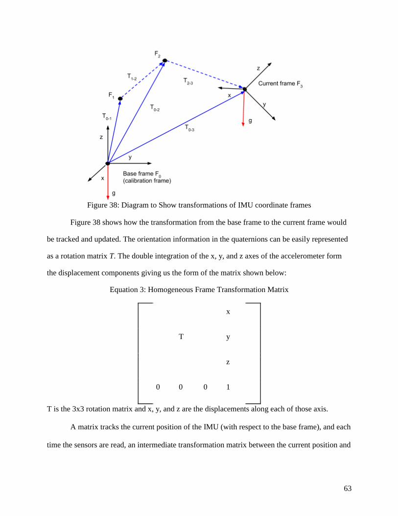
63
Figure 38: Diagram to Show transformations of IMU coordinate frames
Figure 38 shows how the transformation from the base frame to the current frame would
be tracked and updated. The orientation information in the quaternions can be easily represented
as a rotation matrix T. The double integration of the x, y, and z axes of the accelerometer form
the displacement components giving us the form of the matrix shown below:
Equation 3: Homogeneous Frame Transformation Matrix
x
T y
z
0 0 0 1
T is the 3x3 rotation matrix and x, y, and z are the displacements along each of those axis.
A matrix tracks the current position of the IMU (with respect to the base frame), and each
time the sensors are read, an intermediate transformation matrix between the current position and
64
the past current position (T1-2 or T2-3 in Figure 38) is also created. The intermediate transform and
the base frame transform are combined into an updated base frame transform matrix.
Concerns with Position Tracking
The accelerometer readings have some noise and a great amount of drift. Since the
acceleration data accumulates in the velocities which again accumulate in the position that is
being tracked, small errors in acceleration data can have a significant impact on the results. Each
axis of the sensor has different (and inconsistent) error so they must be calibrated separately.
After calibration significant variance persists in the readings that must be accounted for using
tolerancing. Applying tolerances to these readings is difficult because small changes in
acceleration readings could be all that represents a significant change in IMU position, so this
must be done in a way where insignificant changes are ignored, and significant changes are
considered. Another difficulty of the calibration is that the accelerometers measure the force of
gravity acting on them. As the IMU is rotated this force will not be applied along the same axis
as it was when the IMU was calibrated, therefore the rotation matrix generated from the
gyroscope and magnetometer readings is needed to determine the transformation between the
gravity force when calibrated in the base frame and gravity in the frame of the IMU after
rotation.
Based on these considerations the team developed two different approaches to
implementing the IMU for the control guitar string plucks:
1. Using the orientation data exclusively, plucking the strings based on rotations.
2. Using the acceleration readings coupled with the orientation to determine position
and incorporate an external sensor to adjust for drift.

65
The acceleration readings from the IMU alone have too much error to accurately track
position. Although further filtering could be applied to the sensor readings ultimately the drift is
difficult to combat without some other input. Due to the overhead of having to set up both the
IMU and an external sensor for the second proposed control schema, orientation-based control
was used in the final prototype.
Determining Pluck signals and Controlling Device
The final aspect of the wearable device code is detecting when a pluck signal should be
sent. The final control algorithm accomplishes this using only orientation information and
limited motion characteristics. The pitch value from the Euler angles of the IMU is compared to
certain thresholds determined during calibration. The pitch is controlled by the user through
changing the angle of the device. A ‘pluck’ is registered when the motion starts and then stops.
The string signal to be sent when a pluck is registered is based on the angle of the device as
shown in Figure 39. The pluck motion ensures that the wearable device only sends a pluck
message for the last string crossed as opposed to each string. In order to pluck each string
crossed the user must move the device over the entire range in one motion, thus registering a
strum and sending a pluck signal for each of the strings.

66
Figure 39: Plucking Angles
Guitar Device Code Design
The guitar device had to be able to respond to many simultaneous events, such as
plucking one string while receiving a message to pluck to another. The Arduino UNO has a
single core processor and does not have the ability to run multiple loops at once inherently. To
overcome this limitation, “protothreading” was implemented to handle several events.
Protothreads act to replace multithreading on devices that do not have multiple cores by rapidly
calling small functions of non-blocking code. Whereas multithreaded programs run on multiple
stacks in memory, protothreads all run from the same stack and rewind the stack to call on
various threads (Dunkels et al., 2005). Figure 40 represents the main loop and protothread tasks.

67
Figure 40: Guitar Code Architecture
68
Prototyping and Testing
Assembly of Plucker and Frame
For initial testing, a single plucking device was assembled. The initial functional test
resulted in failure; when the motor was activated, the 3D-printed shaft broke under the applied
load, and the shafts bent, causing the gears to slip. The plucking device was redesigned to
account for these problems, while maintaining the same basic mechanism and reusing parts
wherever possible.
Redesigned Plucking Device
To rectify the problems found during prototype testing, the 3D-printed shaft was replaced
by a threaded metal shaft glued to the plectrum. A new frame element was created to support the
shafts on both sides of the gears, preventing the gears from slipping during operation by
significantly reducing the ability of the shafts to bend. Washers were used to provide spacing
between components, reducing friction in the mechanism.
In this design (Figure 41), the motor (1) is held to its frame (2) by a pair of M1.6 screws
and nuts (3,4). The servo armature (14) is held to the motor by a coaxial set screw (not pictured),
and a spline connection transmits torque. The servo armature is cut short to prevent collisions
with the string, and the upper shaft (5) is glued to the armature; the wide connection allows
transmission of torque through contact as well as through the adhesive, increasing the strength of
the connection. The 12mm gear (6) is mounted on the upper shaft and held in place by a radial
0-80 setscrew (not pictured), with additional adhesive strengthening the connection. The upper
shaft is supported on either side by the gear frame (8). The 6mm gear (7) meshes with the 12mm

69
gear and is held to the lower shaft (13) by another radial set screw. Again, the shaft is supported
on either side of the gear by the gear frame (8). The plectrum (11) is mounted on the lower shaft
outside the gear frame; it is glued to the shaft and held in place with a pair of M1.6 nuts and a
small piece of wire through the side of the plectrum. The lower shaft is supported on the far side
of the plectrum by the shaft mounting (12). Spacing between components on shafts is provided
by M2 and M4 washers (10, 9), for the lower and upper shafts, respectively. Initial testing of this
design found that the glue was not sufficient to hold the plectrum to the shaft; after multiple tests
of different plectrum, shaft, and glue options, the final design used two-part epoxy as an
adhesive, mounting a 6mm wide plectrum. The gear frame kept the shafts aligned properly, and
the gears functioned well in multiple tests.
Figure 41: Redesigned Plucking Assembly

70
Table 10: Components of Design
Component Number Component Name
1 Servo Motor
2 Motor Frame
3 M1.6 screw
4 M1.6 nut
5 Upper Shaft
6 12 mm Gear
7 6 mm Gear
8 Gear Frame
9 M4 washer
10 M2 washer
11 Rotating Plectrum
12 Shaft mounting
13 Lower shaft
14 Servo armature
User Interface Devices
Manufacturing and Assembly
The first iteration of both printed circuit boards was printed on copper-clad FR4 with a
LPKF ProtoLaser S4 machine on the WPI campus. These boards have the advantage of being
produced very quickly.

71
Figure 42: PCBs Manufactured on WPI Campus (Wearable Device left, Guitar Device right)
These boards are convenient; however, we determined that for a better end product, we
chose to use an external manufacturer. The boards printed at OSH Park were also printed in
copper-clad FR4, have a purple mask printed over to protect the traces, and have silk-screening
capabilities so that we could label where components are to be plugged in to make it easier for
the end user to assemble. The following pictures are the final boards produced by OSH Park.
Figure 43: PCBs Manufactured Externally (Wearable Device left, Guitar Device right)
The PCBs for both the wearable device and guitar device were assembled such that
components could be switched out if one component was damaged, all the end user would need
to do is to plug in a new one. This was done by mounting male and female headers to the

72
components and PCBs, instead of directly soldering to each other. Figure 44 shows the assembly
of one wearable device unit, and Figure 45 shows the assembly of the guitar device.
Figure 44: Wearable Device Circuit Assembly
Figure 45: Guitar Device Circuit Assembly
User Testing
In order to determine if the user interface device would be capable of giving accurate
readings at the speeds and ranges needed, user testing was required. This also gave the
opportunity to gather subjective feedback about user preference in playing settings. The metric
for judging success at each different setting was the percentage accuracy of notes played which

73
would be automatically recorded. The user interface was tested with 9 people who had no
disability. Three tests were run modifying the calibrated different angles needed to activate a
pluck in each. One test was run at a faster playing speed. The user would control the device by
tilting their hand vertically around the wrist while holding the IMU. The angle of the IMU’s
reading would be used to track the orientation which would be used to determine plucks. A pluck
is registered if the IMU crosses a threshold, defined at regular intervals by the ‘string angle’.
Table 11 shows the details of the tests.
Table 11: Test Details
Range between string
selections (in degrees)
Speed in BPM
Trial 1 15 20
Trial 2 25 20
Trial 3 5 20
Trial 4 15 30
Each user practiced using the device by giving them some time where the ‘plucks’ they
produced were displayed on the screen. Any questions about control of the device were answered
and then the first trial began. During a trial, the user was prompted with different numbers and
had to play them within the allotted time (2-3 seconds depending on trial). At the end of a trial
the accuracy was automatically calculated and printed on the screen to be recorded. The program
would adjust the variables for the next trial (string angle or speed) and prompt the user to
practice with this new control. This process of practicing and playing notes was repeated for each
of the trials. Table 12 shows the results recorded. An image of the test is shown in Figure 46.

74
Figure 46: Sample results from one of the testing trials
Table 12: Test Results
User # Trial 1 accuracy Trial 2 accuracy Trial 3 accuracy Trial 4 accuracy
1 0.69 0.78 0.33 0.81
2 0.89 0.89 0.53 0.75
3 0.81 0.97 0.94 0.92
4 0.94 0.92 0.89 0.69
5 0.78 0.81 0.58 0.67
6 0.92 0.97 0.56 0.86
7 0.89 0.97 0.75 0.61
8 0.89 0.67 0.86 0.61
9 0.56 0.47 0.25 0.33
Average 0.819 0.828 0.632 0.694
Notes to play
Notes played by user

75
The team also asked for feedback from the users about their ability to control the device
and the most comfortable range. The team asked each user the preferred range based on ease of
control. The preferred ranges are shown below in Table 13.
Table 13: Preferred Ranges
Percent preferred by (user could
prefer more than one range) n=9
Small range (5 degrees between notes) 11%
Medium Range (15 degrees between
notes)
55%
Large Range (25 degrees between
notes)
55%
Overall these tests gave some important insight to the limits of the device and the user’s
ability to operate it. Although the accuracy was lower at faster speeds the device was capable of
handling playing speeds much faster than the users were playing. Based on the sample rate of the
IMU, the fastest possible playing speed for the device is 0.0071 seconds per note or 8400 beats
per minute meaning that communication with the IMU will not be a limiting factor in the
response time of the device.

76
Results
Final Device
The final device consists of six plucking devices, each with a rotating plectrum driven by
a servo motor, controlled by a single Arduino UNO and mounted on a frame which holds the
plectrums in position over the guitar strings. Two user interface devices are worn by the user and
send signals to the Arduino on the guitar device, triggering plucks based on the angular
movement of the user’s control site. The position of the guitar in the frame can be adjusted to
account for different distances between the pluckers and guitar strings, while the plucker devices
can be adjusted both along the guitar strings and perpendicular to them to ensure the pluckers are
in an optimal position on any guitar. The plucking devices use a pair of gears to offset the
plectrum from the motor, providing adequate space for the strings, and increasing the rotation
speed of the plectrum relative to the motor. The plucking device drawings are in Appendix J, and
frame drawings are in Appendix K. Assembly instructions for the plucking device are in
Appendix L, for the frame are in Appendix M, and for the user interface are in Appendices N and
O. The following figures are of the device in its final state.
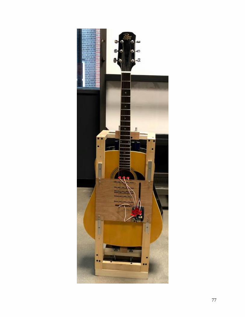
77

78
Figure 47: Final Plucking Device (Top), Close-up View of the Plucking Device (Bottom)
Figure 48: Final Wearable Device

79
Functional Specification Review
The device that was constructed is a functioning guitar plucker. It met the broad project
goals and most of the functional specifications.
Operation
The specification for plucking mechanism operation was that the device must be able to
pluck two guitar strings simultaneously. The device must also support strumming across the full
set of strings and a subset of strings. Finally, the device must not displace a string more than
3.175mm parallel to the guitar body.
The final device can pluck as many strings as the number of wearable devices in use. The
user can trigger a strum effect by quickly crossing each of the six plucking thresholds
consecutively in one movement; this simulates a strum by plucking each string in quick
succession. The final device can strum the full set of strings in either direction. During
operation, strings do not interfere with each other or collide with the body of the guitar, and
notes are played at a reasonable volume.
Frame
The specification for the device requires the frame to not interfere with the resonance of
the guitar and to weigh less than 2 kilograms. The frame should also support guitars ranging in
width from 12 inches to 17 inches, with box heights ranging from 17 inches to 21 inches, and
depths between 3.5 and 5 inches. Finally, the frame should be able to be assembled by hand in
under 10 minutes.
The frame allows the guitar to rest vertically or horizontally and weighs 2.04 kg; with the
plucking device attached, the full device weighs 2.34 kg. It can be attached to a new guitar in

80
under 10 minutes and can be easily adjusted to a wide range of guitar geometries. When the
guitar is played, it can be done so at a reasonable volume, meaning that the resonance of the
instrument is not detrimentally affected.
Forces on Guitar String
The plucking mechanism was required to provide the maximum force to pluck the
strings, which is 3.383 N for the low-E string. The motors used are powerful enough to supply
this force to the string, resulting in successful plucking.
User Control Requirements
The user interface was designed to never need more than the use of two control sites
simultaneously to operate the device, so that the device is not cognitively difficult to use. The
notes are triggered solely by moving the interface devices mounted on the user’s body.
Response Time
The specification for response time was that the latency between the signal trigger and
the corresponding response was no longer than 10ms, which is the equivalent to listening to a
guitar from 10 feet away. This is required so that the user feels in full control while playing the
guitar. Furthermore, the device must be able to play at a rate of 32nd notes at 60 beats per
minute, or 8 notes per second, which is a standard tempo of many songs.
The device experiences an average latency of 17.4ms, which is slightly above the target
of 10 ms. This is still barely within the range of latency perceptible to most humans so it will not
ultimately affect the playing experience. The device can pluck 6 notes per second if the motors

81
are rotating continuously based on both the communication latency and time needed to execute a
plucking motion.
Setup and Calibration
The user interface was required to not require a technical background to use, and that the
device should be setup within 10 minutes, and operable within 2 minutes of being turned on.
The device can easily be attached to a guitar in less than ten minutes, and the microcontroller
startup time once attached is less than a minute.
Manufacturability
The plucking mechanism was required to consist of at least 90% commercially available
parts so that the device could be easily reproducible. The user interface was required to
implement easily affordable and replaceable sensors. The whole device was required to be
assembled using basic tools hand and power tools. The final plucking mechanism uses 86%
commercially available parts (by part count). The custom components need to be 3D printed or
laser cut. The assembly instructions (Appendix J) provide suggestions of sources for the custom
parts, and the files necessary can be found on the public drive linked within that document.
Electronics
The electronics for the device were required to use batteries that were either easily
obtainable or rechargeable. The circuitry had to support replacing components without
knowledge of the total circuit and had to be packaged in a way to prevent accidental unplugging.
The device implements low cost rechargeable lithium ion batteries. The PCBs have
labelled male and female headers so board components can be plugged in and held captive,

82
which prevents the accidental unplugging of board components and does not require the user to
be familiar with the circuit.
Total Cost
The total device cost, including the plucking mechanism, frame, and user interface, must
not exceed $250. The estimated total cost for the final device is $428, with a cost breakdown and
Bill of Materials in Appendix P. The device is more expensive than desired, but some of the
components could potentially be purchased at a lower price. The electronic components were the
most expensive part of the device, with most of the mechanical components relatively cheap to
acquire.

83
Conclusions and Recommendations
Conclusions
The final device has six plucking mechanisms, each positioned over one string of the
guitar, and two user interface devices, which can be strapped to the user’s hand, wrist, or any
other control site. The user interface devices communicate wirelessly with the device on the
guitar, allowing the user to pluck two strings simultaneously. The plucking devices can be
adjusted to ensure that the plectrums are positioned directly above their respective strings, as
well as over the soundhole of the guitar, which ensures the plucks sound natural.
However, the device has some limitations. The motors are programmed to run for a set
time, rather than a set rotation distance, so calibrating the length of a pluck is difficult and
subject to drift. Additionally, moving the plucking devices perpendicular to the strings is
difficult, as each plucker is held in place by six screws, all of which must be loosened to adjust
the mechanism; additionally, it is easy to misalign the components while adjusting them,
resulting in additional strain on the frame elements and increased friction on the shafts.
Recommendations for Future Work
Fretting Device
This project did not develop a means of fretting the guitar; future project could develop
an automatic fretting device and an adaptable user interface, which would greatly increase the
number of songs the user can play, albeit with increased complexity for the user.
84
Actuation Method
One limitation of the current device is the use of continuous rotation servo motors. As
these motors are activated with a rotation speed and duration, they must be calibrated for
accurate rotation distances. Replacing the motors with position-control stepper motors would
allow more precise, reliable control of motor position, allowing easier replacement of
components and adaptation of the design.
Circuit Design
A limitation of the circuit is that the Arduino UNO cannot have code uploaded to it when
the PCB is plugged in. This is because digital pins 0 and 1 are in use and are shared with the
USB serial connection. In a future iteration, the servo motors could be connected to an I2C motor
driver board which would free up 6 digital pins. An added benefit of a motor driver is that the
power for the motors could be supplied independently from the power for the rest of the
microcontroller. A separate solution would be using a microcontroller with more digital pins.
User Interface Modularity
One consideration the project sponsor wanted taken into account was modularity of the
user interface such that the plucker mechanism could be controlled by a variety of methods for a
variety of users. This resulting device does support some modularity; however, with some
caveats. Any sensing system could replace the IMU as long as the device communicates over the
nRF24L01+ radio to the guitar device. It is not possible to plug other sensors into the Arduino
UNO on the guitar device without unsoldering pins from the PCB, and any sensors would have
to be analog devices, as there are no remaining digital pins available.

85
Wearable Device Memory
The low memory available on the Arduino Pro Mini proved to be problematic as it
limited the complexity of the code on the device. The Arduino Pro Mini comes with a
ATmega328P microcontroller running at 8MHz. This board has 32 kB of programmable flash
memory and 2,048 bytes of SRAM (static random-access memory). Flash memory stores the
Arduino sketch and the SRAM stores dynamic variables used in the sketch. The program
necessary to communicate read from the IMU, interpret the sensor readings into device
orientation, determine if a pluck is detected, and communicate the pluck message to the guitar
take up 27,260 bytes (88%) of the program space. The variables used to track the IMU’s
orientation and calibration information take up 1,706 bytes (83%) of the SRAM leaving only 342
bytes for local variables used throughout the program. As a result of these memory constraints
the final version of the program on the wearable device had to be kept very lean, meaning all
debug and testing methods have been placed in separate files. For future iterations of this project
a recommendation would be to use a board with more memory than the ATmega328P to allow
for more complicated processes.
IMU Accuracy
Another area for improvement would be upgrading to a higher precision IMU. Although
a more expensive model would not necessarily be sufficient to facilitate position-based control, it
would allow for better combination of motion and orientation based control. It is hard to confirm
the accuracy of the IMU do to the difficulty of experimenting with acceleration, but the
tolerancing for each of the axis was plus or minus 10% which is very significant.
86
References
Ablenet. Buddy button. Retrieved 10/30, 2018, from https://www.ablenetinc.com/buddy-
button#Description
About stroke. (2018). Retrieved October 10, 2018, from https://www.cdc.gov/stroke/about.htm
Adafruit.com. (2018). Small push-pull solenoid - 12VDC. Retrieved 11/15, 2018, from
https://www.adafruit.com/product/412
Alves-Pinto, A., Turova, V., Blumenstein, T., & Lampe, R. (2016). The case for musical
instrument training in cerebral palsy for neurorehabilitation. Neural Plasticity, 2016
doi:10.1155/2016/1072301
Alves-Pinto, A., Turova, V., Blumenstein, T., & Lampe, R. (2016). The case for musical
instrument training in cerebral palsy for neurorehabilitation. Patrington, East Yorkshire,
U.K. : Freund & Pettman. doi:10.1155/2016/1072301
Amengual, J., Rojo, N., Veciana de las Heras, Misericordia, Marco-Pallarés, J., & Grau-Sánchez,
J. (2013). Sensorimotor plasticity after music-supported therapy in chronic stroke patients
revealed by transcranial magnetic stimulation." PLoS one 8.4 . PLos One, 8(4)
Barlow, H., & Hayes, S. (1979). Alternating treatments design: One strategy for comparing the
effects of two treatments in a single subject. Journal of Applied Behavior Analysis, 12(2),
199-210.

87
Basics about cerebral palsy. (2018). Retrieved October 10, 2018, from
https://www.cdc.gov/ncbddd/cp/facts.html
Bravo, P., LeGare, M., Cook, A., & Hussey, S. (1993). A study of the application of fitts' law to
selected cerebral palsied adults [abstract]. Perceptual and Motor Skills, 77(3), 1107-1117.
Burdon, E., & The Animals. (1964). House of the rising sun
Caulkins, K., & Caulkins, J. (1998). Apparatus for automating a stringed instrument
(US6166307A ed.)
Changing Paces. (n.d.). 6 general types of disabilities.changingpaces.com/6-general-types-of-
disabilities/
Children's Hemiplagia and Stroke Association. (2018). Kids with hemiplegia can play the guitar.
Retrieved 9/29, 2018, from https://chasa.org/kids-with-hemiplegia-can-play-the-guitar/
ChordBuddy guitar learning system. (2018). Retrieved 9/29, 2018, from
https://www.chordbuddy.com
P.A.M. band at 2015 NYC makers faire. Coble, K. (Director). (2015).[Video/DVD] Youtube:
Discovery Channel.
Cooper, M. (1991). In Pitney Bowes Inc. (Ed.), Mechanical guitar strummer (US5212330A ed.)
Cooper, R., Ohnanbe, H., & Hobson, D. (2007). An introduction to rehabilitation engineering.
New York: Taylor & Francis Group, LLC.
88
Day, R. (2018). Pick assists. Retrieved 9/29, 2018, from
http://www.adaysworkmusiceducation.com
digiMike. (2010, Feb 25, 2010, 05:29 pm). Multiple buttons on 1 analog pin. Message posted to
http://forum.arduino.cc/index.php?topic=8558.0
Dube, L., Eaton, M., Kouninis, A., & Zhou, J. (2018). Assistive technology individual guitar
string plucker. (Major Qualifying Project, Bachelor of Science, Worcester Polytechnic
Insititute).
Dunkels, A., Schmidt, O., & Voigt, T. (2005). Using protothreads for sensor node programming.
Unpublished manuscript.
DuPra, A. (2013). Automatic string musical instrument pick system (US8492627B2 ed.)
How playing an instrument benefits your brain - anita collins. Graham, S. (Director).
(2014).[Video/DVD] TED-Ed. Retrieved from https://ed.ted.com/lessons/how-playing-an-
instrument-benefits-your-brain-anita-collins
Graph Tech News. (2017). The acoustics of the guitar . Retrieved 9/26, 2018, from
http://www.graphtech.com/docs/default-document-library/saddlescience.pdf?sfvrsn=2
Hobson, J. (2015, 4/11/2015). Robotic guitar player rocks out on its own. Message posted to
https://hackaday.com/2015/04/11/robotic-player-guitar-rocks-out-on-its-own/
Hoffman, A., & Ault, H. (1996). A retrospective study of the use and abandonment of assistive
devices developed by student design projects. Proceedings of the 1996 RESNA
Conference, pp. 55.

89
Hollis, B. (2017). Physics of sound. Retrieved 9/26, 2018, from https://method-behind-the-
music.com/mechanics/physics/
How to Mechatronics. (n.d.). How to build an arduino wireless network with multiple NRF24L01
modules. Retrieved November 9, 2018, from
https://howtomechatronics.com/tutorials/arduino/how-to-build-an-arduino-wireless-
network-with-multiple-nrf24l01-modules/
Jacobson, E., & Becker, S. (1974). In Jacobson E., Becker S.(Eds.), Power operated guitar
device (US4037503A ed.)
Karmonik, C., Brandt, A., Anderson, J. R., Brooks, F., Lytle, J., Silverman, E., et al. (2016).
Music listening modulates functional connectivity and information flow in the human brain.
Brain Connectivity, 6(8), 632-641. doi:10.1089/brain.2016.0428
Kidwell, R. (1966). Mechanical fingering and picking device for electric bass guitar
(US3443468A ed.)
Lee, J., Leung, J., & Topel, M. (2008). Foot-action guitar strummer. RESNA Annual Conference,
Magnier, C., Thomann, G., Villeneuve, F., & Zwolinski, P. (2012). Methods for designing
assistive devices extracted from 16 case studies in the literature . International Journal on
Interactive Design and Manufacturing, 6(2), 93-100.
Mallin, S., & deCarvalho, H. (2015). Assistive technology and user-centered design: Emotion as
element for innovation. Procedia Manufacturing, 3, 5570-5578.

90
MIT OpenCourseWare. How strings make sound. Retrieved 9/26/2018https://ocw.mit.edu/high-
school/engineering/guitar-building/physics-of-the-guitar/how-strings-make-sound/
Nordic Semiconductor. (2008). nRF24L01+ single chip 2.4 GHz transceiver preliminary product
specification v1.0. Retrieved 2/26, 2019, from
https://www.sparkfun.com/datasheets/Components/SMD/nRF24L01Pluss_Preliminary_Pro
duct_Specification_v1_0.pdf
OHMI Trust. Instruments and instrument makers. Retrieved 10/1, 2018, from
https://www.ohmi.org.uk/instruments.html
Plos, O., Buisine, S., Aoussat, A., Mantelet, F., & Dumas, C. (2012). A universalist strategy for
the design of assistive technology. International Journal of Industrial Ergonomics, 42(6),
533-541.
Pololu. (n.d.). Power HD high-speed digital micro servo DSM44. Retrieved 11/27, 2018, from
https://www.pololu.com/product/2142/specs
Raglio, A., Galandra, C., Sibilla, L., Esposito, F., Gaeta, F., Dalle, F., et al. (2015).
Effects of active music therapy on the normal brain: FMRI based evidence
Springer Science+Business Media New York 2015,
Ramirez, R., & Vamvakousis, Z. (2016). The EyeHarp: A gaze-controlled digital musical
instrument. Frontiers in Psychology, 7
Rand, D. (1986). Mechanical guitar chord maker (US4593595A ed.)

91
Reardon, B. (n.d., ). Robot guitar – bringing unseen data sources into the real world. Message
posted to https://dataviz.com.au/2018/05/16/robot-guitar-bringing-unseen-data-sources-into-
the-real-world/
Sparkfun. SparkFun logic level converter - bi-directional., 2018, from
https://www.sparkfun.com/products/12009
Steinhoff, N., Heine, A. M., Vogl, J., Weiss, K., Aschraf, A., Hajek, P., et al. (2015). A pilot
study into the effects of music therapy on different areas of the brain of individuals with
unresponsive wakefulness syndrome. Frontiers in Neuroscience, Retrieved from
http://link.galegroup.com/apps/doc/A466418543/EAIM?u=mlin_c_worpoly&sid=EAIM&xi
d=5192d7fc
Tabuena, L. (2018). Guitar skills. Retrieved 9/29, 2018, from
http://hhslovelyt.blogspot.com/2018/03/guitar-skills.html
TECHNICally Possible. (2016). Lego guitar robot: A closer look [video file]. Retrieved 10/30,
2018, from https://www.youtube.com/watch?v=EN-7cMjmFv0
The Soundbeam Project. (2018). Soundbeam. Retrieved 9/15, 2018, from
https://www.soundbeam.co.uk/
Tuttle, M. D. (2007). Plucked instrument strings: A combined frequency - time domain wave
approach to investigate longitudinal forces at the bridge support. (Masters in Sound and
Vibration, Chalmers Institute of Technology). (Public)

92
van Wijck, F., Knox, D., Dodds, C., Cassidy, G., Alexander, G., & MacDonald, R. (2012).
Making music after stroke: Using musical activities to enhance arm function. Annals of the
New York Academy of Sciences, 1252(1), 305-311. doi:10.1111/j.1749-6632.2011.06403.x
Vinicola, V., Formisano, R., Penta, F., Matteis, M., Brunelli, S., & Weckel, J. (2001).
Active music therapy in the rehabilitation of severe brain injured patients during coma
recovery Ann. Ist. Super. Sanità, 37(4), pp. 627-630.
Vladsinger. (2008). Harpsichord jack. Retrieved 11/15, 2018, from
https://commons.wikimedia.org/wiki/File:Harpsichord_jack.svg
Walker, M. (January 2005). Optimising the latency of your PC audio interface.
https://www.soundonsound.com/techniques/optimising-latency-pc-audio-interface#7
White, C., Qureshi, A., Singh, V., Krager, J., Porlier, J., Wood, K., et al. (2005). Modular
automated assistive guitar (US7285709B2 ed.)
Wolfe, J. Strings, standing waves and harmonics., 2018, from
https://newt.phys.unsw.edu.au/jw/strings.html
World Health Organization. (2011). International Classification of functioning, disability and
health (ICF).who.int/classifications/icf/en/
Wu, F., Ma, M., & Chang, R. (2009). A new user-centered design approach: A hair washing
assistive device design for users with shoulder mobility restriction. Applied Ergonomics,
40(5), 878-886.

93
Appendices
Appendix A: Fretting Devices
A number of the mechanical guitar-playing devices also included a method for fretting
the individual strings, although many of the methods used would be impractical to operate with
motors. One such method was developed by the aforementioned Kidwell (1966), whose device
(Figure 49) uses a series of oversized levers (104), attached to foot pedals (108), to engage the
frets on specified strings and positions. Each lever is positioned such that when its pedal is
depressed, a fretting pad is brought into contact with a single string on the neck of the guitar,
holding it down and changing the effective length, which in turn changes the frequency the string
vibrates at when plucked or strummed, producing a different note. In a motorized model, the
levers could be operated by linear motors, and would be much smaller; however, the nature of
the design limits the number of strings that could be fretted in a given position, making this
design fairly limited in use.
Figure 49: Lever-actuated system to fret guitar strings (Kidwell, 1966)

94
Another potential fretting device was designed by David Rand (1986), shown in Figure
50. While the previous device fretted single strings, this device is designed to fret specific key
combinations of strings, each combination with a single input. While this reduces the number of
possible combinations, it also reduces the number of inputs required, so the device is much
simpler. This is achieved through a set of specially-designed bars (90-97), each of which fits
around the others and has a single button (90.1), such that the user can finger a full chord with a
single press, rather than needed to hold down each individual string. The bars are held in place
on springs (30), such that releasing the bar is sufficient to release the fretting. In a motorized
device, the bars could be engaged by a linear motor.
Figure 50: Chord-based guitar fretter (Rand, 1986)

95
A similar fretting device was commercialized as the ChordBuddy (ChordBuddy Guitar
Learning System, 2018). The device, shown in Figure 51, has four color-coded buttons
corresponding to the C, D, G, and E minor chords, some of the most common guitar chords.
Each button is mounted to an irregularly-shaped plastic lever, such that when a button is pressed,
the lever engages the appropriate strings of the assigned chord. This allows the user to fret
chords with a single finger, and with a larger target area. It is marketed to the elderly, particularly
those with arthritis, to prevent the pain that traditional fretting can cause; another target market is
young children and others learning to play the guitar, as it simplifies the process of fretting,
making it easier to learn other elements of the music. However, the ChordBuddy costs $45
dollars, so a lower-cost alternative would be desired for use with a full assistive guitar.
Figure 51: ChordBuddy Fretting System (Chordbuddy 2018)

96
Appendix B: Preliminary Plectrum Designs
LEGO Inspired System
Our design was inspired by Youtube user TECHNICally Possible’s Lego Guitar Robot
(TECHNICally Possible, 2016). The device is designed to specifically strum the song “Little
Talks” by Of Monsters And Men. The device is composed of both a plucker and fretter made out
of the LEGO Mindstorms EV3 robotics kit shown in the following picture.
Figure 52: Lego Guitar Robot (TECHNICally Possible, 2016). Screenshot by author.
The plucking device features a revolving platform with a singular pick on a lever. As the
platform rotates forward and back, a pedal (circled in red in the following image) can depress the
lever to raise the pick away from the guitar strings. Depending on the placement of this pedal,
the pick can be controlled to only play both up and down strokes, only the downstrokes, or to
miss the strings completely for a pause in the song (TECHNICally Possible, 2016).

97
Figure 53: Lego Plucking Device (TECHNICally Possible, 2016). Screenshot by author.
This design inspired the following mechanism in Figure 54, which would have six
plectrums on levers driven back and forth by one rotary motor. This rotary motor operates
continuously with variable speed to rock the plectrums back and forth across their assigned
strings.
Figure 54: Rotating Base
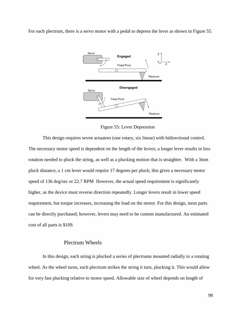
98
For each plectrum, there is a servo motor with a pedal to depress the lever as shown in Figure 55.
Figure 55: Lever Depression
This design requires seven actuators (one rotary, six linear) with bidirectional control.
The necessary motor speed is dependent on the length of the levers; a longer lever results in less
rotation needed to pluck the string, as well as a plucking motion that is straighter. With a 3mm
pluck distance, a 1 cm lever would require 17 degrees per pluck; this gives a necessary motor
speed of 136 deg/sec or 22.7 RPM However, the actual speed requirement is significantly
higher, as the device must reverse direction repeatedly. Longer levers result in lower speed
requirement, but torque increases, increasing the load on the motor. For this design, most parts
can be directly purchased; however, levers may need to be custom manufactured. An estimated
cost of all parts is $109.
Plectrum Wheels
In this design, each string is plucked a series of plectrums mounted radially to a rotating
wheel. As the wheel turns, each plectrum strikes the string it turn, plucking it. This would allow
for very fast plucking relative to motor speed. Allowable size of wheel depends on length of

99
pluck and extension of plectrum beyond the string; the initial assumption was a wheel with a
total diameter of approximately 9mm. Two plectrums per wheel allows relatively high plucking
speed without a need for incredible precision. Small plastic gears with 7mm total diameter (pitch
diameter 6mm), could be fit to the wheel, with a 6mm or 12mm gear fit to the motor to drive.
This would allow the motor to be vertically displaced from the strings, as the motor is likely to
be wider than the plucking wheel.
Figure 56: Plectrum Wheels
This design requires six actuators, one per wheel for each string. Other parts required
include commercially-produced gears, and custom-made wheels. This design can be built by
hand; however, the placement of the wheels needs to be within millimeter precision for both the
horizontal and vertical placement to properly pluck a string. The estimated cost for this design is
about $100 for motors, gears, and raw materials.

100
Four-bar Crank-Rocker Linkage
In this design, a four-bar crank-rocker linkage is situated over each of the six strings of
the guitar; the plectrum is attached to the coupler link. The plane of the linkage is perpendicular
to the body of the guitar, as well as to the direction of the strings. Each rotation of the crank link
results in a single pluck of the strings. The linkage system allows a more complex plucking
motion than other designs, producing a more natural sound. However, the design has significant
problems with its physical layout; the device must be positioned so that the links never collide
with the body of the guitar; in particular, the crank pin must be elevated enough to allow the
crank to rotate fully without striking the guitar; this means that the linkage requires a larger
support structure. This design requires six actuators, one for each linkage; The links and frame
could be laser-cut, with commercial motors. This device would cost roughly $99 for motors and
materials.
Figure 57: Four-bar Linkage
Four-bar Double-Rocker Linkage
In this design, a four-bar double-rocker mechanism would be used to pluck the strings of
the guitar, with one linkage positioned over each string. The plectrum would be mounted on the
coupler link of the linkage, as in the previous design. As the coupler follows a complex curve, its

101
motion path can be optimized to produce a natural plucking motion. The advantage of the
double-rocker system is that only a portion of the coupler curve is swept through by the motion;
this allows a more optimal coupler curve, as the linkage can be limited to only move through the
portion of the cycle that includes the pluck. The device’s primary limitation is the physical
layout of the device; the links must be designed to have the desired coupler curve without
colliding with the body of the guitar. With the limited rotation of the driving link, this is easier
to resolve than in the crank-rocker design, but still a significant challenge. The design again
would use planar, laser-cut parts, with an approximate total cost of $99.
Four-bar Crank-Rocker Linkage
This design consists of a set of four-bar crank-rocker linkages, one for each string. The
plane of the linkage is positioned parallel to the body of the guitar. Similarly to the other linkage
designs, this device would have one linkage for each string to be plucked. Each slider block is
positioned over its string with an attached plectrum, with the central point of the slider’s range
centered on the string’s location. Therefore, the device will pluck the string once for every 180
degrees of rotation in the crank; while the plucking is bi-directional, the motor rotates in the
same direction for every pluck. This design is limited by the necessary size of the components;
assuming the crank pin is in line with the slider, the length of the crank must be half the desired
plucking distance; while offsetting the crank allows for a longer link, the fundamental problem
of link sizing remains. Additionally, the device requires sliding bearings or a similar mechanism
to prevent friction in the slider joint, which results in a significant increase in costs. The design
could use planar links, with commercially available slider bearings and motors, for an estimated
cost of $177.

102
.
Figure 58: Four-bar Crank-Slider
Moving Plectrum
Each plectrum is on a small frame that travels perpendicular to the strings of the guitar;
this device is driven by a rack-and-pinion gear set. This gearset is used to move the device to any
string on the guitar, as well as driving the plectrum across strings to perform plucks and strums.
A second rotary motor is on the moving frame and mounted to the plectrum; this motor rotates
the plectrum out of engagement with the strings, allowing it to travel to the necessary position
without plucking unwanted strings. Two such devices would allow any two strings to be
simultaneously plucked. The primary disadvantage of this device is its speed; rather than simply
initiating a pluck as the single-string plucking designs do, this device must disengage the
plectrum, move to the appropriate string, return the plectrum to the plucking position, and only
then move across the string to pluck. This means that the motors driving the device will need
significantly greater speeds to achieve the same response time as single-string mechanisms.
Additionally, the device needs slider rails to keep the plectrum mount moving in a straight line;
this produces significant friction and requires additional slider bearings to reduce this friction
and ensure the device operates at the necessary speeds. The device has an estimated cost of $97.

103
Figure 59: Moving Plectrum Plucker
Two Robotic Arms
A pair of three degree of freedom robot arms would be responsible for plucking the six
strings. One arm would be located on each side of the strings and each arm would have a
plectrum as an end effector. A strum would be performed by one arm travelling across all six
strings or simultaneous plucking done by having each arm pluck single strings. The device
would be able to pluck all six strings with two devices; however, the mechanism would still have
six degrees of freedom and require six actuators. This design’s main disadvantage is the speed
required; the arm would need to be capable quickly moving to each of the individual strings as
the notes change, requiring significant motion speed to achieve a reasonable response time. The
cost of this device was estimated to be $112.

104
Figure 60: Single Robotic Arm Plucker
Harpsichord Plectrum
Six plectrum devices from harpsichords are used; when triggered, a solenoid pushes a
plectrum across the string. After the pluck is complete, a spring returns the plectrum to its initial
position; The plectrum is mounted on a low-friction lever, or “tongue,” which allows the
plectrum to slip around the string on the return stroke, rather than plucking a second time.
Additionally, a damping pad is brought into contact with the string at the end of the stroke to
quiet the vibrations still introduced by the plectrum. In this design, the plectrum jacks would be
perpendicular to the strings, and parallel to the body of the guitar. The return mechanism of the
jacks allows the design to be used with springed one-way solenoids, which are very low cost; the
initial estimate for this device’s cost is $80.

105
Figure 61: Harpsichord Jack with the plectra up against a string (Vladsinger, 2008)

106
Appendix C: Initial Criteria for Plucker Decision
In order to objectively evaluate the designs, a set of measurable criteria were developed,
with the methodology for each criteria and the rating scale used summarized below.
1. Degrees of Freedom: Evaluating the number of degrees of freedom. With six strings, it
should be possible to play the guitar with a mechanism having a maximum of six degrees
of freedom; a system with fewer degrees of freedom will use fewer actuators and will
have greater efficiency.
2. Response Time: The system must have a response time of less than 0.01 s (10 ms) in
order for the sounds to seem instantaneous. The closer the plucker is to the string at rest,
the shorter the delay between activation and pluck; this will be measured as the fraction
of total pluck cycle distance the device must travel before starting its pluck. Assuming a
constant motor speed and 8 plucks per second, 0.01 s response time is achieved if the
device is at rest no more than 8% of a cycle from the string. Estimate 2 degree angle of
free space/equivalent for linear motion
3. Plucking Speed: Related to response time, plucking speed is the average motor speed
needed to repeatedly pluck the string, at a rate of 8 plucks/second (32nd notes at 60 bpm).
This is a very rough estimate, as the device will probably not be running continuously,
and it does not account for acceleration; however, it functions as a simple approximation
of the motor characteristics required. A lower motor speed will reduce the noise from the
mechanism and be easier to precisely control.
4. Manufacturing Complexity (Acquiring parts): This focuses on how difficult it will be
for the client to acquire all the parts he or she needs in order to make the device; ideally,
the device should be assembled entirely of off-the-shelf parts, but some parts

107
manufactured simply in a makerspace, such as 3d printed plastic parts, laser cut wood or
acrylic, or other similar manufacturing methods, is preferable to custom-manufactured
parts (such as milled metal or hand-carved wood).
5. Manufacturing Complexity (Assembly of Device): Primarily a measure of how
difficult it will be for the client to assemble the device, measured by what tools would be
needed for assembly.
6. Manufacturing Complexity (Number of Parts): How many individual parts are needed
to assemble the device.
7. Manufacturing Complexity (Precision of Assembly): How precisely parts must be
fitted together for the device to function. A device requiring great precision is more
difficult to assemble, and also more vulnerable to parts becoming misaligned over time.
8. Power Required: Estimated total electric power needed to operate the device; this
considers the power needed to run each motor as well as the maximum number of motors
that could be running at one time. A device that uses less power will be easier to adapt to
battery power, which makes the device more portable.
9. Estimated Cost: An estimated cost of the components of the device. The most
expensive component for each device is the motors; other noticeable costs will be any
laser-cut parts and any bearings needed. Small plastic gears are relatively inexpensive, as
are link pins and guitar picks; the cost of an Arduino or similar chip is a factor, but
should not affect the comparison of the designs, as each design should be able to run off
the same chip.
10. Motor Force/Torque Required: The amount of torque or force, for rotary or linear
motors respectively, that is needed to drive the device with the necessary acceleration for
an appropriate response time. The assumption made here is that the device must reach
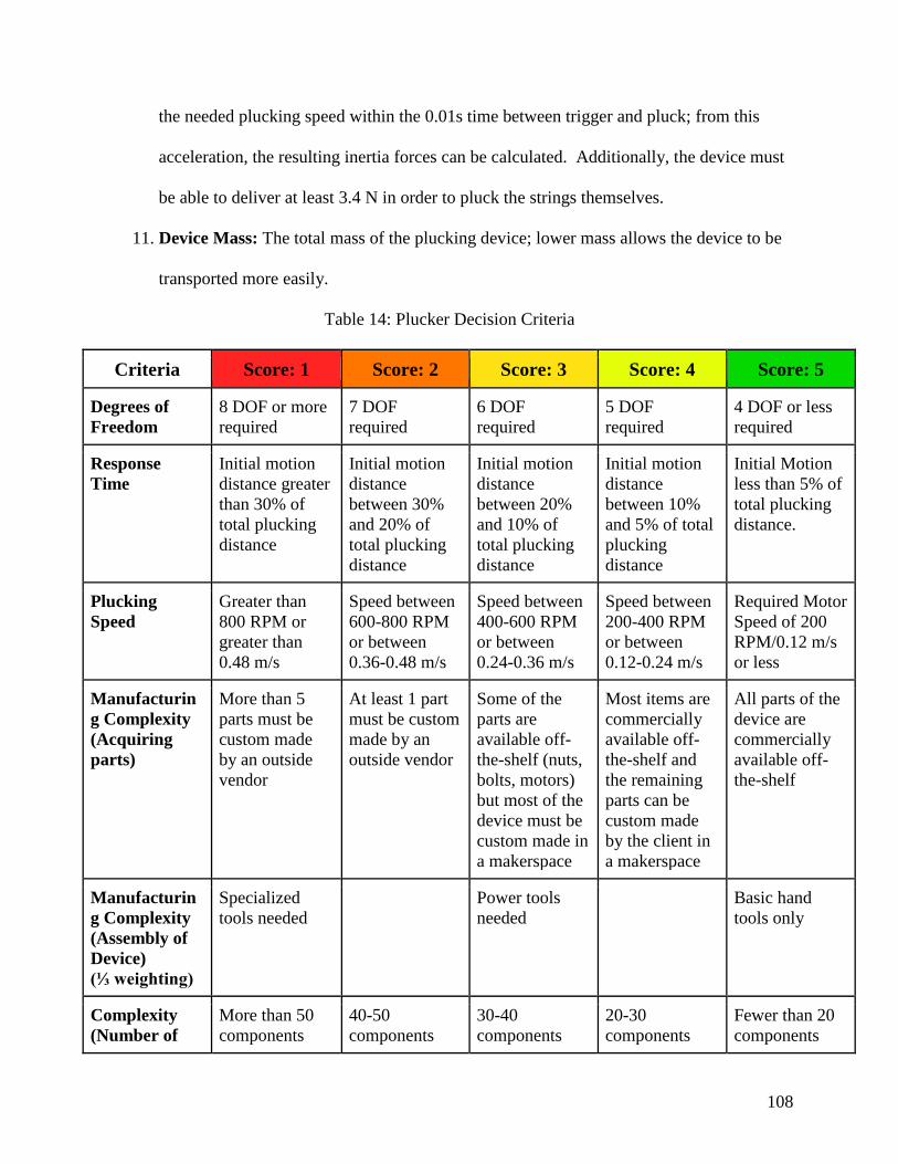
108
the needed plucking speed within the 0.01s time between trigger and pluck; from this
acceleration, the resulting inertia forces can be calculated. Additionally, the device must
be able to deliver at least 3.4 N in order to pluck the strings themselves.
11. Device Mass: The total mass of the plucking device; lower mass allows the device to be
transported more easily.
Table 14: Plucker Decision Criteria
Criteria Score: 1 Score: 2 Score: 3 Score: 4 Score: 5
Degrees of
Freedom
8 DOF or more
required
7 DOF
required
6 DOF
required
5 DOF
required
4 DOF or less
required
Response
Time
Initial motion
distance greater
than 30% of
total plucking
distance
Initial motion
distance
between 30%
and 20% of
total plucking
distance
Initial motion
distance
between 20%
and 10% of
total plucking
distance
Initial motion
distance
between 10%
and 5% of total
plucking
distance
Initial Motion
less than 5% of
total plucking
distance.
Plucking
Speed
Greater than
800 RPM or
greater than
0.48 m/s
Speed between
600-800 RPM
or between
0.36-0.48 m/s
Speed between
400-600 RPM
or between
0.24-0.36 m/s
Speed between
200-400 RPM
or between
0.12-0.24 m/s
Required Motor
Speed of 200
RPM/0.12 m/s
or less
Manufacturin
g Complexity
(Acquiring
parts)
More than 5
parts must be
custom made
by an outside
vendor
At least 1 part
must be custom
made by an
outside vendor
Some of the
parts are
available off-
the-shelf (nuts,
bolts, motors)
but most of the
device must be
custom made in
a makerspace
Most items are
commercially
available off-
the-shelf and
the remaining
parts can be
custom made
by the client in
a makerspace
All parts of the
device are
commercially
available off-
the-shelf
Manufacturin
g Complexity
(Assembly of
Device)
(⅓ weighting)
Specialized
tools needed
Power tools
needed
Basic hand
tools only
Complexity
(Number of
More than 50
components
40-50
components
30-40
components
20-30
components
Fewer than 20
components

109
Parts) (⅓
weighting)
Complexity of
Assembly
(Precision
Required) (⅓
weighting)
more precise
than 0.1 mm
0.1-1 mm
precision
needed
1-10 mm
precision
needed
10mm-1cm
precision
needed
less precise
than 1 cm
Voltage
Required
More than 12
volts
9-12 volts 0-9 volts or less
needed
Estimated
Cost of Final
Design
More than $175 $150-175 $125-150 $100-125 Less than $100
Motor
Force/Torque
Required
Greater than 0.1
Nm Torque, or
Greater than 6.5
N linear Force
0.075-0.1 Nm
Torque, or 5.5-
6.5 N linear
Force
0.05-0.075 Nm
Torque, or 4.5-
5.5 N linear
force
0.025-0.05 Nm
Torque, or 3.5-
4.5 N linear
Force
Less than 0.025
Nm of torque
required or less
than 3.5 N of
linear force
required
Device Mass Greater than 4
kilograms
3-4 kilograms
grams
2-3 kilograms
grams
1-2 kilograms Less than 1 kg
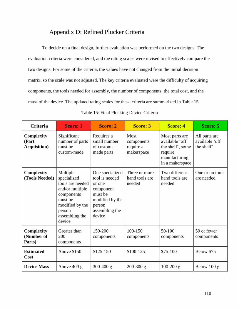
110
Appendix D: Refined Plucker Criteria
To decide on a final design, further evaluation was performed on the two designs. The
evaluation criteria were considered, and the rating scales were revised to effectively compare the
two designs. For some of the criteria, the values have not changed from the initial decision
matrix, so the scale was not adjusted. The key criteria evaluated were the difficulty of acquiring
components, the tools needed for assembly, the number of components, the total cost, and the
mass of the device. The updated rating scales for these criteria are summarized in Table 15.
Table 15: Final Plucking Device Criteria
Criteria Score: 1 Score: 2 Score: 3 Score: 4 Score: 5
Complexity
(Part
Acquisition)
Significant
number of parts
must be
custom-made
Requires a
small number
of custom-
made parts
Most
components
require a
makerspace
Most parts are
available ‘off
the shelf’, some
require
manufacturing
in a makerspace
All parts are
available ‘off
the shelf’
Complexity
(Tools Needed)
Multiple
specialized
tools are needed
and/or multiple
components
must be
modified by the
person
assembling the
device
One specialized
tool is needed
or one
component
must be
modified by the
person
assembling the
device
Three or more
hand tools are
needed
Two different
hand tools are
needed
One or no tools
are needed
Complexity
(Number of
Parts)
Greater than
200
components
150-200
components
100-150
components
50-100
components
50 or fewer
components
Estimated
Cost
Above $150 $125-150 $100-125 $75-100 Below $75
Device Mass Above 400 g 300-400 g 200-300 g 100-200 g Below 100 g

111
Appendix E: Preliminary User Interface Designs
Camera
This design uses a camera to track brightly colored patches placed on the user on two
similar control sites, most likely both hands or both feet. As the location of colored squares move
across the camera’s field of view the guitar strings would be plucked. To create a strumming
effect the user would need to quickly move one of the control sites over all six of the “strings”
(indicated by lines of the white backdrop). This would involve setting up a white backdrop with
indicators to reduce visual noise in the camera’s input. Due to the limitations of the camera there
could be issues in some lighting situations and the camera would need to be calibrated each time
the device is set up to correctly identify the colored squares. This would also require the user to
wear colored patches which although unlikely could be an issue for some users. Each of the
strings are 12 cm apart, multiplied by the six strings give 72 cm wide required range of motion in
the X axis (as labeled in the figure). The speed at which the guitar could be played would be
dependent on the user’s speed moving across this 72 cm space. The user would also need to be
able to keep the colored squares relatively level in the camera’s field of view which could be
tiring over several minutes of playing. The cost for the camera is $31.50. The computation
necessary to process the input from the camera is complicated which could slow down response
time slightly.

112
Figure 62: Camera UI Setup
Inertial Measurement Unit
This design would utilize a pair of Inertial Measurement Units (IMUs) to track the
position of two control sites on the user; notably these control sites can be dissimilar and
calibrated separately. The calibration would involve moving the IMU to three points which
would be set as the center, high E and low E string locations. The other strings would be filled in
based on these measurements. As the location of IMUs move across the calibrated field of strings
the guitar strings would be plucked. To create a strumming effect, the user would need to quickly
move one of the control sites over all six of the “strings”. To help the user play correct notes,
tape could be used to indicate how the system had been calibrated. The range of motion for this
device is very flexible, since it is entirely determined through calibration. The range of possible
distances is from 12 cm to 240 cm (oriented on any axis). This could have therapeutic value as
well as practical value for making the device easier for individuals to play. The IMU would need
to be attached to the user with Elastic or Velcro. Any control site that could provide the required
range of motion and is able to have an IMU attached would be considered viable for this
approach. Attaching and calibrating the device are the only steps of set up making this device
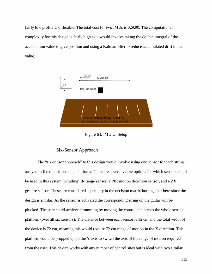
113
fairly low profile and flexible. The total cost for two IMUs is $29.90. The computational
complexity for this design is fairly high as it would involve taking the double integral of the
acceleration value to give position and using a Kalman filter to reduce accumulated drift in the
value.
Figure 63: IMU UI Setup
Six-Sensor Approach
The “six-sensor approach” to this design would involve using one sensor for each string
arrayed in fixed positions on a platform. There are several viable options for which sensors could
be used in this system including; IR range sensor, a PIR motion detection sensor, and a ZX
gesture sensor. These are considered separately in the decision matrix but together here since the
design is similar. As the sensor is activated the corresponding string on the guitar will be
plucked. The user could achieve strumming by moving the control site across the whole sensor
platform (over all six sensors). The distance between each sensor is 12 cm and the total width of
the device is 72 cm, meaning this would require 72 cm range of motion in the X direction. This
platform could be propped up on the Y axis to switch the axis of the range of motion required
from the user. This device works with any number of control sites but is ideal with two similar

114
locations such as both hands, both elbows, or both feet. The setup is very minimal since there is
no calibration and the array of sensors is already fixed on a platform. The cost depends on the
sensor used but is around $83. Since this approach requires six sensors it can be more expensive.
The simplicity of the design would make the computation fairly minimal.
Figure 64: Six Sensor Array UI Setup
Digital Sensor Approach
This design is very similar to the six-sensor approach but opts to use digital, tactile
sensors. The sensors the team is considering for this design are 100mm arcade buttons, rocker
switch, and toggle switch. These are considered separately in the decision matrix but together
here since input selection does not affect the overall design much. The six inputs would each
correspond to one of the strings and would activate the corresponding string when activated. The
range of motion required of the user is 72 cm in the X axis and +/- 5 cm in the Y axis to toggle
the inputs. This design would require the user to exert small force. Due to the range of motion
required to flip a switch or press a button this design is mostly conducive to being used by hands
or potentially feet but would be difficult to use with any other control site. Computationally this
would be the simplest of the designs.

115
Figure 65: Digital Sensor Array Setup
Spectroscopy
This design would implement a spectral sensor capable of detecting different colors. The
used would hold up cards of different colors to the two sensors and based on the colors shown a
string on the guitar would be plucked. This design would require the user to be able to identify
and pick up the correct card and then move the card in front of the sensor. This would require
varying amounts of motion on the X-axis and 15 cm of motion on the Y axis since the sensors
would be supported on stilts. Since this sensor uses light the lighting conditions in the room this
is used in could affect the results. This design has an issue regarding the speed at which the notes
could be played. Since our requirement is 8 notes per second it would be very difficult to pick up
and display that many cards even for a person without limitations.

116
Figure 65: Spectropic Sensor UI Setup

117
Appendix F: Initial Criteria for User Interface Decision
The criteria used to evaluate these initial designs were:
1. Power Requirements: power requirements needed for user interface, as compared to
Arduino’s power supply
2. Direction of motion requirement: types of motions on different axis required to operate
device
3. Range of motion requirement: range of motion required from user measured in cm in x,
y, and z axis
4. Control sites supported: number of control sites the design would viably work on
5. Viability for different ranges of motion: can the design be adapted to different motion
ranges
6. Time for calibration: how long does it take for a sensor to become operable
7. Steps needed to calibrate: what tasks must be done for a sensor to become operable
8. Setup time: estimated time to physically set up user interface
9. Estimated Computational complexity: what is the delay between sensor reading and
calculated output for the guitar
10. Cost: total cost of sensors and additional hardware
11. Input detail: input resolution from binary to 10 bit
12. User Difficulty: measurement of how long it takes a user from triggering one note to
triggering another note
These criteria were then made into a rubric and evaluated on a scale of 1 - 5, with 1 being the
worst, and 5 being the best. The rubric is presented in Table 16.
Table 16: User Interface Decision Criteria
Criteria Score: 1 Score: 2 Score: 3 Score: 4 Score: 5
Power
Requirements
Draws more
than 150mA
on 3V or 1A
on 5V pins
Requires
more than
Arduino 5V
pin
Fits Arduino
power
requirements
Direction of Rotational Rotational Linear Linear Linear

118
motion
requirement
motion 3
axes
Motion 2
axes
Motion 3
axes /
Rotational
Motion 1 axis
motion 2
axes
motion 1
axis
Range of
motion
requirement
Motion
greater than
1 meter/
less than 5
cm
Motion
within 5 cm
to 1 m
Control sites
supported
Can only be
controlled
by specific
part of the
body
Can be
controlled by
several parts
of the body
Can be
controlled by
any moving
part of the
body
Viable for
different
ranges of
motion
Motion
requirement
cannot be
adjusted
Motion
requirement
can be
switched
between
settings
Motion
requirement
can be
determined
by user
Time for
calibration
> 2 minutes 1 - 2 minutes 30 seconds -
1 minute
< 30 seconds No
calibration
required
Steps for
calibration
Requires
additional
tools
More than 1
step
1 step
Setup time > 10
minutes
5 - 10
minutes
< 5 minutes
Estimated
Computational
Complexity
Requires
additional
board /
Delay of 1
ms
Delay of 1- .5
ms
Delay of .1
ms
Delay of .1
ms - .1 μs
Delay of < .1
μs
Cost > $100 $75 - $100 $50 - $75 $25 - $50 < $25
Input Detail Binary 2 bit
resolution
4 bit
resolution
8 bit
resolution
10 bit
resolution
User Difficulty > 1 second 1 - ½ second ½ - ¼ second ¼ - ⅛ second < ⅛ second
119
Appendix G: Refined User Interface Criteria
To choose a final design, these additional criteria that were not previously evaluated will
also be used. Table 10 has these additional criteria, and the criteria that were re-evaluated from
the previous decision matrix.
1. Final Cost: A better estimate on what the design will cost
2. Manufacturing of custom parts method: What technologies are required to build the
user interface
3. Repairability: What steps are needed to repair the interface should a component break
4. How fast does error accumulate: time in which error will have noticeable change in
user experience. This metric determines how often calibration must occur.
5. Need for code editing when parts are replaced: what kind of changes to the code must
occur when components are switched out. Certain electronic components may give a
different reading between units. The end user should have to change the code as little as
possible after they replace something in the physical interface.

120
Table 17: Additional Decision Criteria
Criteria Score: 1 Score: 2 Score: 3 Score: 4 Score: 5
Final Cost Above $75 $56-$74 $41-$55 $26 - $40 Under $25
User Difficulty Majority of
individuals
in user group
can not play
song at real
time
Minority of
individuals in
user group
cannot play
song at real
time
All
individuals in
user group
can play song
at real time
Effect on user
body
Multiple
conditions in
user group
experience
pain or
deterioration
of body
Single
condition in
user group
experience
pain or
deterioration
of body
No
individuals in
user group
are affected
Manufacturing
of custom
parts method
Less
accessible
technologies
like laser
cutting, CNC
More
accessible
technologies
like 3D
printing
No
manufacturin
g of custom
parts
Repairability Unsoldering Unplugging
Error
accumulation
rate
Faster than
30 seconds
30 seconds -
1 minute
1 minute - 2
minutes
2 minutes - 3
minutes
Slower than 3
minutes or no
error
Need for code
editing when
parts are
replaced
Editing of
code
functionality
Editing of
defined
constants
No editing
required
121
Appendix H: Wearable Device Code

122

123
124

125
Appendix I: Guitar Device Code

126

127

128
Appendix J: Plucker Design Drawings
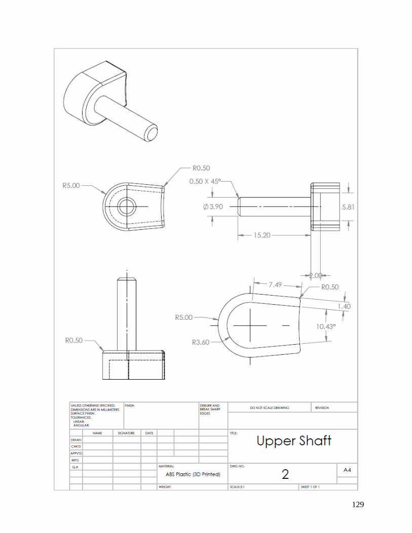
129

130

131

132

133

134
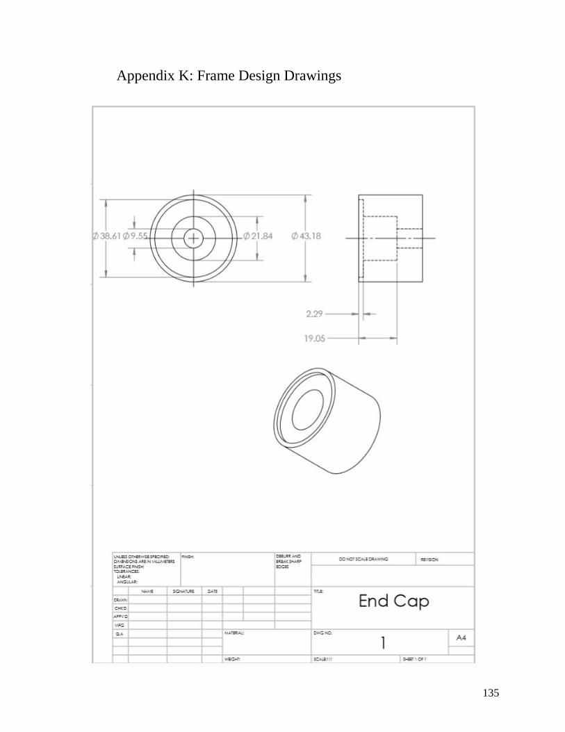
135
Appendix K: Frame Design Drawings

136

137
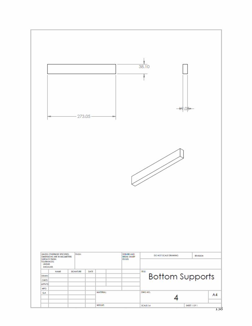
138

139

140

141
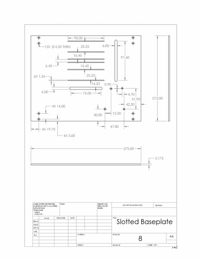
142

143

144

145

146
Appendix L: Plucker Assembly Guide
1. General Information
1.1. Suggested Purchases
Links to purchase components are given; these were where the team bought those components, as well as possible sources for 3d-printed components; there are alternative retailers available. For 3d-printed parts, high precision is needed. The team used machines with a layer thickness of 0.001 inches and accuracy of about 0.003 inches; while these values do not represent a hard limit on precision required, lower-precision parts could have poor fits for the screws and shafts.
1.2. Tools
The following list of tools is needed to assemble the plucking device: ● Set of allen wrenches (specifically 1.5 mm and 0.028”) ● Small clamp or vise to secure parts ● Needle-nose Pliers (optional) ● Thread cutters sized for 2mm shafts ● Heavy-duty Adhesive, such as 2-part epoxy ● Power drill (3/64” or #56 bit) ● 0-80 hand tap ● Craft knife or X-acto knife
1.3. Suggested Assembly Practices
The following is a list of tips to make assembly more easy ● Be careful when cutting the threaded rod; use thread cutters rather than standard
clippers or a hacksaw to preserve the threads. ● Give glue time to set; different adhesives take different amounts of time to cure, and the
device should not be run until the glue is at full strength. ● When tightening screws, hold the nut in place with pliers and tighten with the allen
wrench.

147
2. Assembly Instructions
2.1. Components
The following is a list of the components required for 1 plucking device; six pluckers are required in total. For 3D-printed parts, STL files can be found on the public drive (https://drive.google.com/drive/folders/1_12EsLgG01R4oxDcKvJM7nvIhAhizcgi?usp=sharing), as well as SolidWorks part files which can be downloaded and edited if necessary.
Component Quantity Image Link to purchase
Servo motor 1
https://www.pololu.com/product/2820/specs
Servo armature and set screw
1
Included with motor purchase
Upper shaft 1
3d printed (https://us.protiq.com/)
6 mm gear 1
https://www.mcmaster.com/2662N27

148
12 mm gear 1
https://www.mcmaster.com/2662n28
Motor frame 1
3D printed (https://us.protiq.com/)
Upper shaft (threaded)
1 (total, each device uses a short section)
https://www.mcmaster.com/90024a210
Plectrum 1
3D printed (https://us.protiq.com/)
Set Screw 2
https://www.mcmaster.com/92311a050
Fastener Screw 8
https://www.mcmaster.com/91292a311

149
Fastener Washer 6
https://www.mcmaster.com/91166a170
Fastener Nut 8
https://www.mcmaster.com/90591a109
Upper Shaft Washer
2
https://www.mcmaster.com/93475a230
Lower Shaft washer
1
https://www.mcmaster.com/93475a195
Lower Shaft Nut 2
https://www.mcmaster.com/90592a075
Gear Frame 1
3D printed (https://us.protiq.com/)
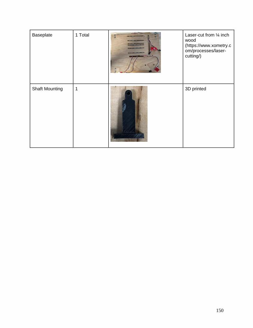
150
Baseplate 1 Total
Laser-cut from ¼ inch wood (https://www.xometry.com/processes/laser-cutting/)
Shaft Mounting 1
3D printed

151
2.2. Assembly
Follow the steps below to assemble one plucking device onto the baseplate. Six devices in total are needed.
1. Slide the motor frame over the front of the motor; ensure that the ‘feet’ (circled in red) are on the side further from the motor shaft (circled in light blue), as shown.
2. Use two M1.6 screws and nuts (circled below) to secure the motor to its frame; position
the head of the screw on the front of the motor, closer to the shaft.
3. Clip the end of the single-arm servo armature so that it is similar in shape to the slotted
end of the larger gearshaft, as shown. The armature should be cut at the third small hoe from the center, but the precise location is not critical.
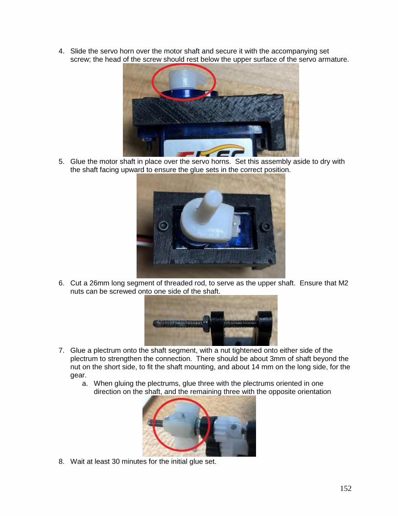
152
4. Slide the servo horn over the motor shaft and secure it with the accompanying set screw; the head of the screw should rest below the upper surface of the servo armature.
5. Glue the motor shaft in place over the servo horns. Set this assembly aside to dry with
the shaft facing upward to ensure the glue sets in the correct position.
6. Cut a 26mm long segment of threaded rod, to serve as the upper shaft. Ensure that M2
nuts can be screwed onto one side of the shaft.
7. Glue a plectrum onto the shaft segment, with a nut tightened onto either side of the
plectrum to strengthen the connection. There should be about 3mm of shaft beyond the nut on the short side, to fit the shaft mounting, and about 14 mm on the long side, for the gear.
a. When gluing the plectrums, glue three with the plectrums oriented in one direction on the shaft, and the remaining three with the opposite orientation
8. Wait at least 30 minutes for the initial glue set.

153
9. Drill a small hole through the side of the plectrum, and insert a segment of wire and additional glue into the hole.
10. Let the glue set (2-part epoxy takes 24 hours). 11. Drill a 3/64” pilot hole in the hub of each gear, for the set screw.
12. (optional) Tap the pilot hole (cut threads into the material) to make it easier to tighten the
set screw. 13. Slide the long end of the plectrum shaft through the gear frame, an M2 washer,and
through the 6mm gear. A second washer should be placed on the other side of the gear.
14. Apply glue to the setscrew hole. Tighten the setscrew into the hole to push glue into the
shaft.
15. Remove the setscrew and repeat step 14 at least 4 times to ensure enough glue is
between the shaft and gear. Leave the setscrew tightened against the shaft for additional strength.
16. Allow the glue sufficient time to cure. 17. Make sure there is no glue beween the teeth of the gear; if glue is present, clear it out
with a craft knife. 18. Slide the large shaft through the gear frame, and through the large 12mm gear and M4
washer.
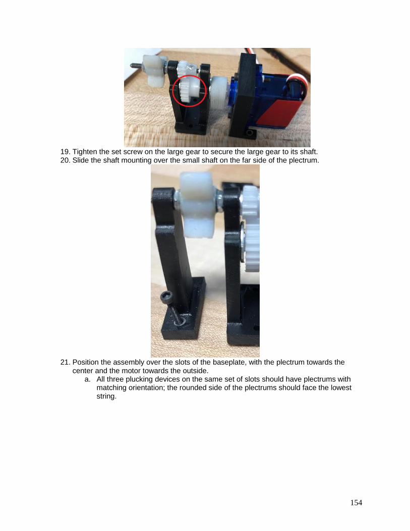
154
19. Tighten the set screw on the large gear to secure the large gear to its shaft. 20. Slide the shaft mounting over the small shaft on the far side of the plectrum.
21. Position the assembly over the slots of the baseplate, with the plectrum towards the
center and the motor towards the outside. a. All three plucking devices on the same set of slots should have plectrums with
matching orientation; the rounded side of the plectrums should face the lowest string.

155
22. Slide M1.6 screws, 6 in total, through the holes on the frame and the slots on the
baseplate. 23. Place a washer and nut on the end of each screw; secure the nuts but leave some
looseness for adjustment.
24. Place all six plucking devices on the baseplate, following the directions above. 25. Lead the motor wires through the wide slots.
26. Use electrical tape to tape the wires to the back of the motors, keeping them away from
the strings.

156
27. (optional) Use electrical tape to label each wire; plucking device 1 is above the low E
string.

157
Appendix M: Frame Assembly Guide
1. General Information
1.1. Suggested Purchases
For both the different parts of the frame, the links to purchase components are given. This is where the team bought the components, but there are other alternative retailers.
1.2. Tools
The following list is all of the tools required to assembly the frame. ● Drill ● Hack Saw ● Miter Saw or Hand Saw ● Assorted Standard drill bits ● Sockets ● 2 part epoxy ● Tape Measure ● Dremel
1.3. Suggested Assembly Practices
The following is a list of tips for assembling the frame. ● For more consistent and straighter cuts use the miter saw. ● Make sure to let the E600 Industrial Adhesive cure for 72 hours before use to allow for
maximum strength. ● Label the wood parts as you cut them to allow. This will help make sure that you don’t
mix any parts up
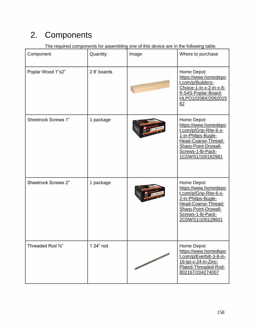
158
2. Components
The required components for assembling one of this device are in the following table.
Component Quantity Image Where to purchase
Poplar Wood 1”x2” 2 8’ boards
Home Depot: https://www.homedepot.com/p/Builders-Choice-1-in-x-2-in-x-8-ft-S4S-Poplar-Board-HLPO10208X/206201562
Sheetrock Screws 1” 1 package
Home Depot: https://www.homedepot.com/p/Grip-Rite-6-x-1-in-Philips-Bugle-Head-Coarse-Thread-Sharp-Point-Drywall-Screws-1-lb-Pack-1CDWS1/100162981
Sheetrock Screws 2” 1 package
Home Depot: https://www.homedepot.com/p/Grip-Rite-6-x-2-in-Philips-Bugle-Head-Coarse-Thread-Sharp-Point-Drywall-Screws-1-lb-Pack-2CDWS1/100128601
Threaded Rod ⅜” 1 24” rod
Home Depot: https://www.homedepot.com/p/Everbilt-3-8-in-16-tpi-x-24-in-Zinc-Plated-Threaded-Rod-802167/204274007
https://www.homedepot.com/p/Builders-Choice-1-in-x-2-in-x-8-ft-S4S-Poplar-Board-HLPO10208X/206201562
https://www.homedepot.com/p/Builders-Choice-1-in-x-2-in-x-8-ft-S4S-Poplar-Board-HLPO10208X/206201562
https://www.homedepot.com/p/Builders-Choice-1-in-x-2-in-x-8-ft-S4S-Poplar-Board-HLPO10208X/206201562
https://www.homedepot.com/p/Builders-Choice-1-in-x-2-in-x-8-ft-S4S-Poplar-Board-HLPO10208X/206201562
https://www.homedepot.com/p/Builders-Choice-1-in-x-2-in-x-8-ft-S4S-Poplar-Board-HLPO10208X/206201562
https://www.homedepot.com/p/Builders-Choice-1-in-x-2-in-x-8-ft-S4S-Poplar-Board-HLPO10208X/206201562
https://www.homedepot.com/p/Everbilt-3-8-in-16-tpi-x-24-in-Zinc-Plated-Threaded-Rod-802167/204274007
https://www.homedepot.com/p/Everbilt-3-8-in-16-tpi-x-24-in-Zinc-Plated-Threaded-Rod-802167/204274007
https://www.homedepot.com/p/Everbilt-3-8-in-16-tpi-x-24-in-Zinc-Plated-Threaded-Rod-802167/204274007

159
Wing Nut 4
Home Depot: https://www.homedepot.com/p/Everbilt-3-8-in-16-tpi-Coarse-Stainless-Steel-Wing-Nut-800231/204274212
Nut 1 package
Home Depot: https://www.homedepot.com/p/Everbilt-25-Piece-per-Bag-3-8-in-16-TPI-Zinc-Plated-Hex-Nut-802364/204274093
Washers 1 package
Home Depot: https://www.homedepot.com/p/Everbilt-3-8-in-Zinc-Plated-Flat-Washer-25-Pack-802324/204276362
Mouse Pad 1
Best Buy: https://www.bestbuy.com/site/insignia-mouse-pad-black/7536185.p?skuId=7536185
Low-Profile Sleeve Bearing
Carriages and Guide Rail
(Part # 6723K5 & 6723K9)
2 rails, 4 plastic carriages
McMaster-Carr: https://www.mcmaster.com/linear-shafts
3D Printed End Caps 4
3d printed (https://us.protiq.com/)

160
3. Assembly
3.1. Pre-Assembly
Before the assembly of the frame, it is easier to do all the cutting and measuring. Below is a list of parts that will need to be cut with names that can be used to identify them by later.
Using the 2x1 Poplar Wood
1. Horizontal Supports: 2 pieces 27” 2. Short Frame: 5 pieces 7” ⅝ 3. Bottom Supports: 2 pieces 10 ¾ 4. Angled Supports: 4 pieces 5. Neck Rest: 1 pieces 4 ½ 6. Vertical Supports: 4 pieces 7”
Using any piece of wood that fits the requirements
1. Button Strap Holder: 1 piece 2”x1 ½”x4 ½” For the Threaded Rod Supports
1. Threaded Rod: 4 pieces 4 ½ 2. Mouse Pads: 4 pieces
3.2. Assembling the Wooden Structure
It is recommended that you pre-drill holes before drilling in screws to help prevent splitting, but it is not required.
1. Take the two horizontal supports and place them parallel to each other, lie them flat on a solid flat surface and place a short frame support in between and perpendicular to the two longer pieces so if is flush with one of the end
2. Using 4 2” sheetrock screws, screw the three pieces together. There should be 1 screw at each of the arrows shown in the following image. The place where this short frame has been place will now be designated at the bottom of the entire assembly to help with future orientation.
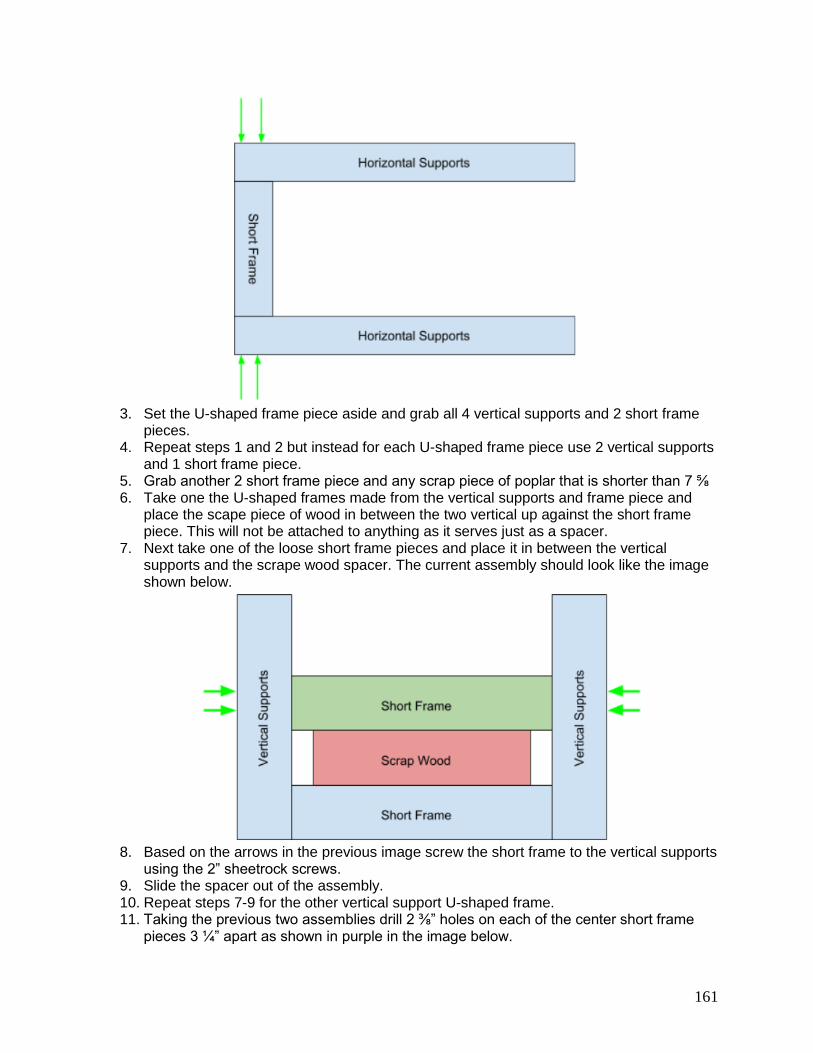
161
3. Set the U-shaped frame piece aside and grab all 4 vertical supports and 2 short frame
pieces. 4. Repeat steps 1 and 2 but instead for each U-shaped frame piece use 2 vertical supports
and 1 short frame piece. 5. Grab another 2 short frame piece and any scrap piece of poplar that is shorter than 7 ⅝ 6. Take one the U-shaped frames made from the vertical supports and frame piece and
place the scape piece of wood in between the two vertical up against the short frame piece. This will not be attached to anything as it serves just as a spacer.
7. Next take one of the loose short frame pieces and place it in between the vertical supports and the scrape wood spacer. The current assembly should look like the image shown below.
8. Based on the arrows in the previous image screw the short frame to the vertical supports
using the 2” sheetrock screws. 9. Slide the spacer out of the assembly. 10. Repeat steps 7-9 for the other vertical support U-shaped frame. 11. Taking the previous two assemblies drill 2 ⅜” holes on each of the center short frame
pieces 3 ¼” apart as shown in purple in the image below.

162
12. Get the U-shaped frame piece made from the horizontal supports and place the other
two pieces on the ends as shown in the image below.
13. Gather all 4 angle supports and using the 1“ screws screw one into each corner of the
connections you just made together.
14. Locate the bottom of the assembly and the 2 bottom supports. These supports will be
used to help the entire assembly stand on its own even after the threaded rods are inserted. Using the 2” screws come in from the top as indicated in the figure below, this will help keep the bottom smooth to prevent rocking.
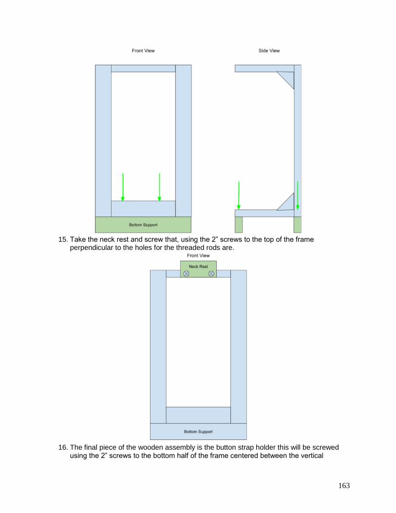
163
15. Take the neck rest and screw that, using the 2” screws to the top of the frame
perpendicular to the holes for the threaded rods are.
16. The final piece of the wooden assembly is the button strap holder this will be screwed
using the 2” screws to the bottom half of the frame centered between the vertical

164
supports as shown below. There should also be a deep hole in this piece that is 1” diameter, 3 ½” high and centered across.
17. The final wooden structure will look like the image below.
3.3. Assembling the Threaded Rod Supports
Below will be the instructions for making a threaded rod support but note that there needs to be 4 total threaded rod assemblies so plan to do each step a total of four times
1. Using a sanding head of the Dremel dress up the cut ends of the threaded rod to allow for nuts to be able to screw onto it.
2. Take one of the 3D printed end caps and screw it onto one of the ends of the rod. This should be done so that the flat end of the end cad is facing the center of the rod. Keep screwing until the end of the rod that went through the cap is flush with the depressed section’s surface, this will later be used to help keep the mouse pad solid as it will later sit up against it.

165
3. Take two of the nuts, put one on either end of the threaded rod and tighten then up against the end cap. BEWARE: you want them tight but make sure not to over tighten otherwise you could crack the plastic of the end cap.
4. Mix some of the 2 part epoxy up by following the instructions on the bottles and use it to glue the mouse pads down into the depression on the end cap, this can include sticking glue onto the end of the rod inside the end cap so that the mouse pad can also stick there.
5. Let the rods dry for 24 hours to allow for the glue to fully set. 6. You end rods should look like this.
3.4. Combining the Assembly
1. With the glue fully set on the rods the can then be put into the frame. One threaded rod goes through each of the holes with a washer and nut on each side of the frame.
2. The final few step involve attaching the linear slide tracks. These sit on the front face of the horizontal pieces, the need to be parallel to each other and the spacing has to be just the right distance so that the baseplate will slide though the rails easily.
3. In order to get the spacing correct, it is recommended that you attach the inner slides to the baseplate and slide the rails on while they are not attached to anything. Then lay the rails down on the horizontal pieces and mark out the holes for one of the tracks.
4. Using a 3 m drill bit, drill holes on the mark for one of the rails. 5. Place the rail over the holes and fit the screws through. This will hold that rail in place
while marking out the holes for the second rail. 6. If separated slide the in rails back through the linear slide on the guitar and mark out the
holes for the second track. 7. Once all marked out drill the new holes using the 3 m drill bit. 8. Using a screwdriver and socket tighten the nuts and bolts to hold down the linear slide
onto the frame. 9. Without the guitar the finished frame will look like the one in the image below
10. To put the guitar in the frame, make sure all the end caps are retracted as far as the can
go. Stick the neck in between the 2 horizontal supports and lay it on the neck rest. The

166
using a slight amount of force push the bottom back of the frame down so it flexes until you can slide the strap button into the large block with the hole that will hold in in place.
11. Slide the baseplate onto the linear slides 12. Using a ruler push the guitar either up or down the frame to adjust the distance of the
strings the bottom of the baseplate. The goal distance is ~36 mm. 13. Once the guitar is at the correct distance away from the baseplate tighten the end caps
up to the body of the guitar.

167
Appendix N: PCB Assembly Guide
1. General Information
1.1. Suggested Purchases
For both the wearable device PCB and the guitar PCB, the links to purchase components are given. This is where the team bought the components, but there are other alternative retailers.
1.2. Tools
The following list is all of the tools required to assembly the devices. ● Soldering iron ● Soldering “Helping Hands” or “Third Hand” stand ● Needle-nose pliers ● Flat-nose pliers ● X-ACTO knife ● Wire cutters ● Multimeter (optional) ● Breadboard (optional)

168
1.3. Suggested Assembly Practices
The following is a list of tips for assembling the devices. ● To cut female headers easily, count the number of pins and then then use needle-nose
pliers to pull out the pin next to the amount needed. Score the plastic housing with the X-ACTO knife and break the section away from the rest. See this video for more assistance: https://youtu.be/qDG3VFSMSPQ
● Sometimes components can be stabilized when soldering by plugging pins (that won’t be soldered!) into a breadboard
● Probing the leads with the multimeter after soldering is important to ensure that no pins have been unintentionally connected.
1.4. Files to Download ● To edit the printed circuit boards or to order more of them. The files are located in this
folder: https://drive.google.com/open?id=1LfEdh0aBH9-G25bImzNXmDTE7EtxqKcL ● To have more boards manufactured, upload the GBRS zip files for either the wearable
device or guitar device to an online manufacturer such as Osh Park. ● To open the PROJECT zip files and make edits to the boards, download Kicad here:
http://kicad-pcb.org/download/
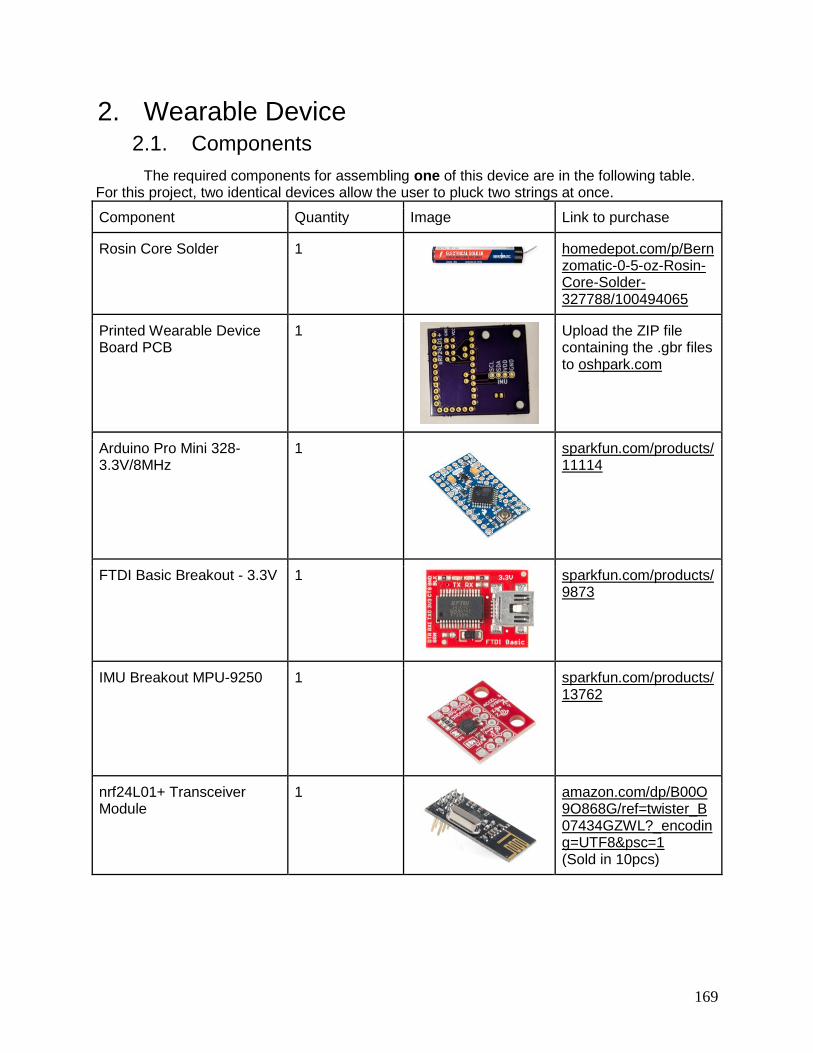
169
2. Wearable Device 2.1. Components
The required components for assembling one of this device are in the following table. For this project, two identical devices allow the user to pluck two strings at once.
Component Quantity Image Link to purchase
Rosin Core Solder 1
homedepot.com/p/Bernzomatic-0-5-oz-Rosin-Core-Solder-327788/100494065
Printed Wearable Device Board PCB
1
Upload the ZIP file containing the .gbr files to oshpark.com
Arduino Pro Mini 328- 3.3V/8MHz
1
sparkfun.com/products/11114
FTDI Basic Breakout - 3.3V 1
sparkfun.com/products/9873
IMU Breakout MPU-9250 1
sparkfun.com/products/13762
nrf24L01+ Transceiver Module
1
amazon.com/dp/B00O9O868G/ref=twister_B07434GZWL?_encoding=UTF8&psc=1 (Sold in 10pcs)

170
400mAh Lithium Ion Battery 1
sparkfun.com/products/13851
LiPo Charger Micro USB (requires micro USB cable and wall wart to be used, which are not listed)
1
sparkfun.com/products/10217
JST Vertical Connector 1
sparkfun.com/products/8613
Female Headers 2
sparkfun.com/products/115
Arduino Stackable Header Kit - R3
1 (can be shared across building 2 units)
sparkfun.com/products/11417
Break Away Headers - Straight
1
sparkfun.com/products/116
Electrolytic Decoupling Capacitor - 10uF/25V
1
sparkfun.com/products/523

171
2.2. Assembly
Follow the steps below to assemble one wearable device unit. 1. Cut the male headers to size. Two sections of 12 pins, two sections of 2 pins, one
section of 6 pins, and one section of 4 pins are needed. 2. Cut the female headers to size. Two sections of 12 pins, two sections of 2 pins, and
three sections of 4 pins are needed 3. Cut one stackable header to a length of 6 pins. 4. Trim the capacitor leads to 3mm. 5. Solder the 4 pin section of male headers to the IMU SCL, SDA, VDD, and GND pins as
shown in the following image
6. Solder the 6 pin section of male headers to the Programming Header pins (BLK, GND,
VCC, RXI, TXO, GRN) and the 12 pin and 2 pin sections of female headers to the rest of the pins on the Arduino Pro Mini as shown in the following image.
7. Put the PCB such that the “IMU” and “nrf24L01+” screen printing facing up. This will be
referred to as the top of the PCB. 8. Solder the 4 pin sections of female headers to that side of the PCB into the holes labeled
for the IMU and nrf24L01+ as shown in the following image

172
9. Solder the 12 pin and 2 pin sections of male headers by plugging the short side of the
header up into the PCB and leaving the long side of the PCB to face out the other side of the board. See the preceding image for how this should look on the top of the PCB and the following image to see how this should look on the bottom of the PCB.
10. Flip the PCB over so that the bottom side is facing up. 11. Solder the JST vertical connector into the holes marked Vin and GND such that the plug
is facing out of the PCB as shown in the following image
12. Solder the 6 pin section of the stackable header to the pins labelled BLK, GND, VCC,
RXI, TXO, GRN, shown in the following figure

173
13. Solder the capacitor to the VCC and GND leads sticking up from the previously soldered
female headers of the nrf24L01+. It is very important that the polarity of the capacitor is correct. The negative symbol, as in the following images, must be connected to the GND pin which is boxed in.
14. Plug the components as shown in the following image, with the IMU and nrf24L01+ on
the top of the board and the Arduino Pro Mini on the bottom of the board!

174
3. Guitar Device 3.1. Components
The required components for assembling this device are in the following table.
Component Quantity Image Link to purchase
Rosin Core Solder 1
homedepot.com/p/Bernzomatic-0-5-oz-Rosin-Core-Solder-327788/100494065
Printed Guitar Board PCB 1
Upload the ZIP file containing the .gbr files to oshpark.com
Arduino UNO - R3 1
sparkfun.com/products/11021
nrf24L01+ Transceiver Module
1
amazon.com/dp/B00O9O868G/ref=twister_B07434GZWL?_encoding=UTF8&psc=1 (Sold in 10pcs)
1Ah Lithium Ion Battery 2
sparkfun.com/products/13813
LiPo Charger Micro USB (requires micro USB cable and wall wart to be used, which are not listed, two could be purchased to charge the batteries at the same time)
1
sparkfun.com/products/10217

175
JST Vertical Connector 2
sparkfun.com/products/8613
Female Headers 1
sparkfun.com/products/115
Break Away Headers - Straight
2
sparkfun.com/products/116
Electrolytic Decoupling Capacitor - 10uF/25V
1
sparkfun.com/products/523
FEETECH FS90R Micro Continuous Rotation Servo
6
pololu.com/product/2820/specs
100Ω Resistor 1
sparkfun.com/products/14493
Momentary Pushbutton Switch
1
sparkfun.com/products/9190

176
LED - RGB Addressable, PTH, 8mm Diffused
1
sparkfun.com/products/12877

177
3.2. Assembly
Follow the steps below to assemble the guitar device. 1. Cut the male headers to size. Six sections of 3 pins, two sections of 8 pins, one section
of 6 pins, and one section of 10 pins are needed. 2. Cut the female headers to size. Two sections of 4 pins are needed. 3. Trim the capacitor leads to 3mm. 4. Solder the capacitor to the nrf24L01+ GND and VCC pins. It is very important that the
polarity of the capacitor is correct. The negative symbol, as in the following image, must be connected to the GND pin, which is indicated on the chip with a square around the pin. See the following image as a reference.
5. Put the PCB side with the screen printing up. 6. Solder the 3 pin sections of male headers, with the long part facing up, into the sections
labeled for the servos, as shown in the following image.
7. Solder the two 4 pin sections of female headers into the pins labeled for the nrf24L01+,
as shown in the following image.
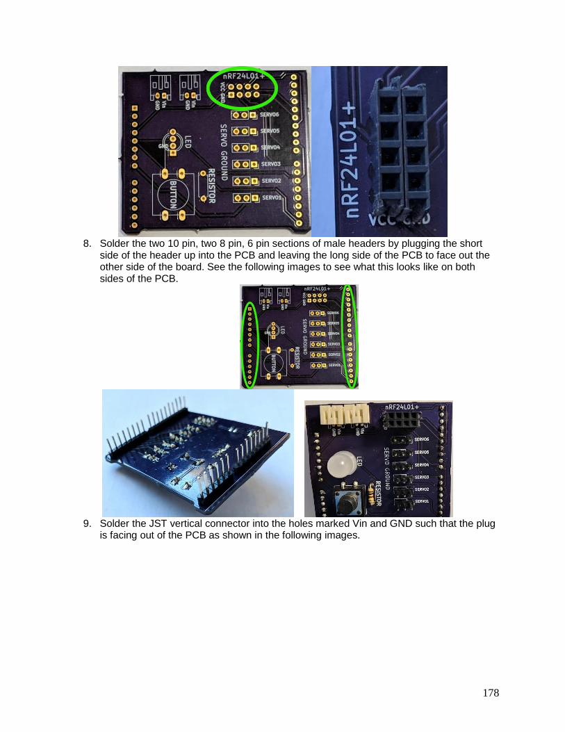
178
8. Solder the two 10 pin, two 8 pin, 6 pin sections of male headers by plugging the short
side of the header up into the PCB and leaving the long side of the PCB to face out the other side of the board. See the following images to see what this looks like on both sides of the PCB.
9. Solder the JST vertical connector into the holes marked Vin and GND such that the plug
is facing out of the PCB as shown in the following images.

179
10. Separate the leads of the LED such that it will plug into the PCB. Trim the leads such that a solderable amount is left on the other side of the board. Plug the LED into the PCB such that the flat edge of the bulb is facing towards the spot for the button. The GND pin will line up with labelled pin, shown in the following images
11. Plug the button into the square labelled for it. It will require some force to do this. Solder
all 4 pins of the button to the PCB, shown in the following image

180
12. Bend the resistor leads such that it will plug into the holes labelled for it. Trim the leads
such that a solderable amount is left on the other side of the board, shown in the following image
13. Plug the PCB into the Arduino UNO, and the nrf24L01+ and servos into the PCB!
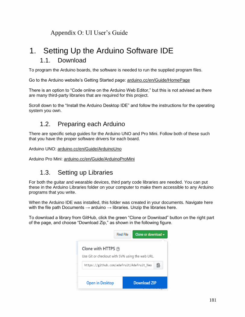
181
Appendix O: UI User’s Guide
1. Setting Up the Arduino Software IDE 1.1. Download
To program the Arduino boards, the software is needed to run the supplied program files. Go to the Arduino website’s Getting Started page: arduino.cc/en/Guide/HomePage There is an option to “Code online on the Arduino Web Editor,” but this is not advised as there are many third-party libraries that are required for this project. Scroll down to the “Install the Arduino Desktop IDE” and follow the instructions for the operating system you own.
1.2. Preparing each Arduino
There are specific setup guides for the Arduino UNO and Pro Mini. Follow both of these such that you have the proper software drivers for each board. Arduino UNO: arduino.cc/en/Guide/ArduinoUno Arduino Pro Mini: arduino.cc/en/Guide/ArduinoProMini
1.3. Setting up Libraries
For both the guitar and wearable devices, third party code libraries are needed. You can put these in the Arduino Libraries folder on your computer to make them accessible to any Arduino programs that you write. When the Arduino IDE was installed, this folder was created in your documents. Navigate here with the file path Documents → arduino → libraries. Unzip the libraries here. To download a library from GitHub, click the green “Clone or Download” button on the right part of the page, and choose “Download Zip,” as shown in the following figure.

182
For the guitar device, download these libraries: ● Arduino NeoPixel: github.com/adafruit/Adafruit_NeoPixel ● Arduino Thread: github.com/ivanseidel/ArduinoThread ● Circular Buffer: github.com/rlogiacco/CircularBuffer
For the wearable device, download these libraries:
● SparkFun MPU-9250 9 DOF IMU Breakout: github.com/sparkfun/SparkFun_MPU-9250_Breakout_Arduino_Library
Libraries used by both components
● RF24: github.com/nRF24/RF24 ● RF24 Network: github.com/nRF24/RF24Network

183
2. Programming the Wearable Devices 2.1. Download the Code
Download the final_wearable_device.zip from this folder: https://drive.google.com/drive/folders/1-QPQxh47PpdBu0vI1Eli7cAf32kYZGA2?usp=sharing and save it to the Documents → arduino folder.
2.2. Opening the Project
Open final_wearable_device.ino project.
2.3. Uploading Code to the Arduino Pro Mini
To program the device, plug the FTDI Basic Breakout into the stackable header pins facing the top of the board, such that the BLK, GND, VCC, RXI, TXO, GRN pins match up, shown below.
Then plug the FTDI Basic Breakout into a mini USB cable and into a computer. In the Arduino IDE, make sure the settings under the Tools menu match the correct board, as shown in the following image.

184
Upload the code to the board using the upload button, shown in the image below.
2.4. Running the Device
Once the program has successfully been uploaded to the board, unplug the FTDI board. Plug the battery into the JST connector.

185
3. Programming the Guitar Device 3.1. Download the Code
Download the GuitarDeviceCode.zip from this folder: https://drive.google.com/drive/folders/1-QPQxh47PpdBu0vI1Eli7cAf32kYZGA2?usp=sharing and save it to the Documents → arduino folder.
3.2. Opening the Project
Open GuitarDeviceCode.ino project.
3.3. Uploading Code to the Arduino UNO
To program the device, remove the PCB from the Arduino first. This is important as pins 0 and 1 are being used by the button and a servo, but must share functionality with the USB connection. After removing the PCB, then plug in the USB cable to the Arduino and computer. In the Arduino IDE, make sure the settings under the Tools menu match the correct board, as shown in the following image.
Then, upload the code to the board using the upload button, shown in the image below.
3.4. Running the Device
Once the program has successfully been uploaded to the board, unplug the USB cable. Plug the PCB back into the Arduino and both batteries into the JST connectors. Make sure to plug the batteries in to the PCB before plugging any servos into the board, because the batteries cannot handle the instantaneous current draw of all servos turning on at the same time.

186
Appendix P: Final Cost and Bill of Materials
Parts Unit Cost Quantity Total Cost Link
6mm gear $2.05 6 $12.30 https://www.mcmaster.com/2662n27
12mm gear $2.09 6 $12.54 https://www.mcmaster.com/2662n28
2mm shaft (300 mm length) $4.32 1 $4.32 https://www.mcmaster.com/94185a571
0-80 set screws (pkg. of 50) $8.78 1 $8.78 https://www.mcmaster.com/92311a050
M1.6 washers (pkg. of 100) $1.44 1 $1.44 https://www.mcmaster.com/91166a170
M2 washers (pkg. of 100) $1.06 1 $1.06 https://www.mcmaster.com/93475a195
M4 washers (pkg. of 100) $2.05 1 $2.05 https://www.mcmaster.com/91166a230
M1.6 hex nuts (pkg. of 50) $9.13 1 $9.13 https://www.mcmaster.com/90591a109
M2 hex nuts (pkg. of 100) $1.12 1 $1.12 https://www.mcmaster.com/90592a004
M1.6 socket-head screws (pkg. of
25) $8.16 2 $16.32 https://www.mcmaster.com/91292a311
Servo motors $4.95 6 $29.70
https://www.pololu.com/product/2820/spe
cs
4mm shaft (3D printed) $0.45 6 $2.70
Plectrum (3D printed) $0.30 6 $1.80
Motor Frame (3D printed) $2.25 6 $13.50
Gear Frame (3D printed) $2.55 6 $15.30
Gearshaft Mount (3D printed) $1.35 6 $8.10
Baseplate (Laser-cut) $10.00 1 $10.00
IMU Casing Top (3D Printed) $1.40 2 $2.80
IMU Casing Bottom (3D Printed) $1.68 2 $3.36
Poplar 1"x2"x8' Board $10.16 2 $20.32
Sheetrock Screw2 1" $6.97 1 $6.97
Sheetrock Screws 2" $6.97 1 $6.97
Threaded Rod 3/8"x24" $1.97 1 $1.97
Wing Nut 3/8" 16 tpi $1.18 4 $4.72
Nut 3/8" 16 tpi $2.97 1 $2.97
Washers 3/8" $3.45 1 $3.45
Mouse Pad $4.99 1 $4.99
Low-Profile Sleeve Bearing
Carriages $0.05 4 $0.20
Guide Rail $5.35 2 $10.70

187
End Caps (3D printed) $2.54 4 $10.16
Rosin Core Solder $3.97 1 $3.97
https://www.homedepot.com/p/Bernzom
atic-0-5-oz-Rosin-Core-Solder-
327788/100494065
Wearable Device PCB (set of 3) $10.90 1 $10.90 https://oshpark.com/
Guitar Device PCB (set of 3) $21.55 1 $21.55 https://oshpark.com/
Arduino Pro Mini 328-
3.3V/8MHz $9.95 2 $19.90
https://www.sparkfun.com/products/111
14
Arduino UNO - R3 $22.95 1 $22.95
https://www.sparkfun.com/products/110
21
FTDI Basic Breakout - 3.3V $15.50 1 $15.50
https://www.sparkfun.com/products/987
3
IMU Breakout MPU-9250 $14.95 2 $29.90
https://www.sparkfun.com/products/137
62
nrf24L01+ Transceiver Module
(Pack of 10) $11.98 1 $11.98
https://www.amazon.com/dp/B00O9O86
8G/ref=twister_B07434GZWL?_encodin
g=UTF8&psc=1
400mAh Lithium Ion Battery $4.95 2 $9.90
https://www.sparkfun.com/products/138
51
1Ah Lithium Ion Battery $9.95 2 $19.90
https://www.sparkfun.com/products/138
13
LiPo Charger Micro USB $8.95 1 $8.95
https://www.sparkfun.com/products/102
17
JST Vertical Connector $0.95 4 $3.80
https://www.sparkfun.com/products/861
3
Female Headers $1.50 5 $7.50 https://www.sparkfun.com/products/115
Arduino Stackable Header Kit -
R3 $1.50 1 $1.50
https://www.sparkfun.com/products/114
17
Break Away Headers - Straight $1.50 3 $4.50 https://www.sparkfun.com/products/116
Electrolytic Decoupling Capacitor
- 10uF/25V $0.45 3 $1.35 https://www.sparkfun.com/products/523
100Ω Resistor (pack of 20) $1.20 1 $1.20
https://www.sparkfun.com/products/144
93
Momentary Pushbutton Switch $0.50 1 $0.50
https://www.sparkfun.com/products/919
0
LED - RGB Addressable, PTH,
8mm Diffused (pack of 5) $2.95 1 $2.95
https://www.sparkfun.com/products/128
77
TOTAL: $428.44