
Assessment of Corona/Arcing Hazard for Electron …...NASA Technical Memorandum 108525 Assessment of...
12
NASA Technical Memorandum 108525 Assessment of Corona/Arcing Hazard for Electron Beam Welding in Space Shuttle Bay at LEO for ISWE: Test Results A.C. Nunes, Jr., C. Russell, J. Vaughn, C. Stocks, D. O'Dell, and B. Bhat Marshall Space Flight Center • MSFC, Alabama National Aeronautics and Space Administration Marshall Space Flight Center ° MSFC, Alabama 35812 November 1996 https://ntrs.nasa.gov/search.jsp?R=19970005301 2020-07-12T13:00:45+00:00Z
Transcript of Assessment of Corona/Arcing Hazard for Electron …...NASA Technical Memorandum 108525 Assessment of...

NASA Technical Memorandum 108525
Assessment of Corona/Arcing Hazardfor Electron Beam Welding in SpaceShuttle Bay at LEO for ISWE: Test Results
A.C. Nunes, Jr., C. Russell, J. Vaughn, C. Stocks, D. O'Dell, and B. Bhat
Marshall Space Flight Center • MSFC, Alabama
National Aeronautics and Space AdministrationMarshall Space Flight Center ° MSFC, Alabama 35812
November 1996
https://ntrs.nasa.gov/search.jsp?R=19970005301 2020-07-12T13:00:45+00:00Z
ACKNOWLEDGMENTS
The authors would like to gratefully acknowledge the assistance of:
The UHT technicians from the Paton Electric Welding Institute in the Ukraine, who operatedthe UHT, V. Shulim,V. Demyanenko, and A. Zagrebelnij, and their translator from SAIC, O.Germash.
• The MCI contractors from MSFC, who quickly found and repaired vacuum chamber leaks,
enabling completion of the tests.
• The Space Environment Effects Branch of Lewis Research Center, particularly D. Fergusonand R. Chock, who read and commented on the test plan.
• The Johnson Space Center reviewers of the test plan, A. Reubens and M. Pedley, and S.Koontz.
• Numerous others at MSFC, particularly R. Carruth, D. Mitchell, and M. Vanhooser, who
supported the test in technical or administrative ways.
ii

TABLE OF CONTENTS
INTRODUCTION: WHY THIS STUDY WAS UNDERTAKEN ....................................
PLAN OF THE EXPERIMENT ............................................................................
EXPERIMENTAL RESULTS ..............................................................................
INTERPRETATION OF RESULTS ...... : ................................................................
CONCLUSIONS .............................................................................................
REFERENCES
Page
1
1
3
5
5
6
°,°
111
Figure
1.
2.
LIST OF ILLUSTRATIONS
Title
Simplified UHT power circuit showing current measurement sites .........................
Sample current,/SAMPLE (upper curve), tool cathode current,/TOOL (middle curve),
and power supply current, IPOWER (bottom curve) for run 3 .................................
Page
3
4
Table
1.
2.
LIST OF TABLES
Title
Measured currents .................................................................................
Test matrix .........................................................................................
Page
3
4
iv

TECHNICAL MEMORANDUM
ASSESSMENT OF CORONA/ARCING HAZARD FOR ELECTRON BEAM WELDING IN
SPACE SHUTTLE BAY AT LEO FOR ISWE: TEST RESULTS
INTRODUCTION: WHY THIS STUDY WAS UNDERTAKEN
This study was undertaken to ensure that no hazard would exist from unwanted electrical
discharges, i.e., arcing or corona, during the electron beam welding exercise required for the InternationalSpace Welding Experiment (ISWE).
Welding carried out as early as 1984 by the Soviets with the Ukrainian Universal (Electric Beam
Welding) Hand Tool (UHT) do not seem to have resulted in any unwanted electrical discharges. Therehave been no reports of such. The body of the UHT is grounded, and high voltages are restricted to thefilament region inside the UHT body.
The only arcing encountered in commercial electron beam welding takes place inside the electronbeam gun in the region between the high-voltage filament and the grounded accelerating anode. Shouldthis take place, commercial equipment has circuitry to detect it and to shut off the beam power.
It is possible, however, that the pressure in the enclosed space shuttle bay may be higher than thatencountered by the Soviets in their extravehicular activity (EVA) welding experiment. Gas pressuremeasurements made on space shuttle mission STS-39 yielded rvnical nressures of around 104 torr with
• ..7.4 . -J .17 .L' ,
fluctuations to around 10 torr.] It was calculated that the leakagefrom a space suit, or extravehicularmobility unit (EMU), could produce a pressure rise to 10-4 torr in the neighborhood of the UHT.
Because of the potentially higher pressures to be encountered in the shuttle bay in proximity to aleaky EMU, it was deemed advisable to operate the UHT under higher pressures than anticipated to seewhether any signs of unwanted or dangerous electrical discharges would be observed.
PLAN OF THE EXPERIMENT
A range of pressures starting from within the normal UHT operating range below 10-4 torr(depending upon the capability of the vacuum chamber) and rising to 10-3 torr, an order of magnitudeabove the highest anticipated pressure level, was selected.
Argon gas was used to pressurize the chamber because of oxygen's detrimental effect on diffusion
pumps and apparatus in the vacuum chamber. A precedent for the use of argon to test for arcing potentialhas already been set by tether arcing simulation studies. The following brief discussion of the physicsunderlying the beginning of electrical discharges explains why argon may be substituted for air with nosubstantial loss of verisimilitude and points out the factors limiting incipient discharges. Only the initiationof discharges is discussed and not the more complicated subsequent developments of intensification,sustainment, etc.
Electrical discharge processes start when an electron emitted from a surface or from a gas atom(caused by, say, the impact of a random photon) picks up enough energy from the ambient electric field to
produce more electrons when it collides with a gas atom in its vicinity. The newly emitted electrons pro-duce still more electrons in subsequent collisions and induce an avalanche of electrons. At sufficiently highpressures (dependent upon the ambient electric field), discharges do not occur because the electron mean
freepathbetweencollisionsis too shortfor theelectronto pickupenoughenergybetweencollisionstocausetheemissionof electrons.Thissituationis notof concernhere.
At sufficientlylow voltage,belowthe"minimumsparkingpotential,"electricaldischargesdonotoccurat anypressure.Theminimumsparkingpotentialhasto beabovetheionizationpotentialof thegas.Theionizationpotentialsof oxygenandnitrogenare14.5and 13.6V, respectively,andtheminimumsparkingpotentialof air is around275V. "Thus,for example,a spark will notpass below about 275 V inair, no matter what the conditions. Similar values hold for other gases, being lowest for the inert ones,
especially when slightly impure, such as He or Ne with A or Hg present, and for electrodes of low workfunction. ,,2
The ionization potential of argon is 15.8 V, a bit above but not far from that for nitrogen andoxygen, so it is not surprising that a similar minimum sparking potential is reported. Note that the elec-trode, which emits a spark, also has an effect upon the minimum sparking potential, because secondaryelectrons are emitted from the electrode as well as from the gas due to the action of impinging ions. Here,
however, the 8,000 V potential level exceeds the 275 V minimum sparking potential so greatly that themechanism of ionization is not of great concern.
At sufficiently low pressures, electrical discharges do not occur because there are not enough avail-able atoms to collide with. Given a voltage V acting across a gap distance d, a discharge cannot occur if the
pressure P of the gas in the gap is so low that the mean free path A of the gas atoms is greater than the gapwidth d. Given a collision cross section ty with a particular gas (on the order of nr 2, where r is the radius
of a monatomic gas atom) an electron sweeps a volume era between collisions. The swept volume betweencollisions should be the same as the volume occupied by a single gas atom, approximately kT/P, where kis Boltzmann's constant; T, the absolute temperature; and P, the pressure of the gas. Thus, _ is found tobe kTItrP, and hence an electrical discharge should not occur unless d is greater than kTItyP or Pd isgreater than kT/tr. For nitrogen the approximate atomic radius is 1.06x10 -10 m; 3 0.25x10 -1° m if singlyionized to the +1 state. 4 Oxygen ionized to +1 has an approximate radius of 0.22x10 -l° m and1.76x10 -1° m in the -1 state. Argon has an approximate atomic radius of 1.9x10 -i° m and 1.54x10 -1° min the +1 ionized state. Since the smaller Pd, the greater the likelihood of an electrical discharge, argon
appears to be more likely to show a discharge than air. It may be added that given the use of laboratorytemperatures rather than the higher temperatures of the atmosphere at Low Earth Orbit (LEO), the presenttest appears still more conservative. Thus, argon gas is deemed a conservative equivalent to air for the
purpose of modeling electrical discharge behavior.
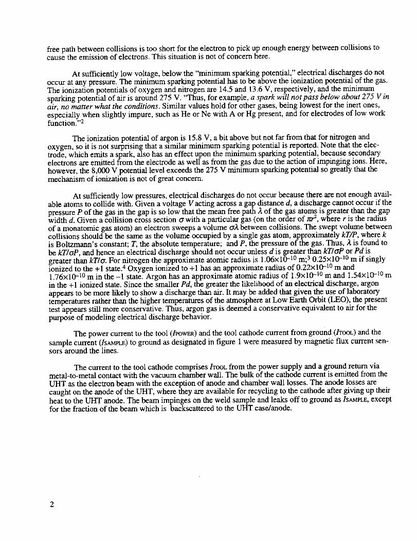
The power current to the tool (/POWER) and the tool cathode current from ground (/TOOL) and the
sample current (/SAMPLE) tO ground as designated in figure 1 were measured by magnetic flux current sen-sors around the lines.
The current to the tool cathode comprises/TOOL from the power supply and a ground return viametal-to-metal contact with the vacuum chamber wall. The bulk of the cathode current is emitted from the
UHT as the electron beam with the exception of anode and chamber wall losses. The anode losses arecaught on the anode of the UHT, where they are available for recycling to the cathode after giving up their
heat to the UHT anode. The beam impinges on the weld sample and leaks off to ground as/SAMPLE, exceptfor the fraction of the beam which is backscattered to the UHT case/anode.

Vacuum Chamber
•J - Anode r._s I
g-8kV _ /1.8_' I _°l -_s'°]
J__ 6 V Power
( ( (1 Supply
I Sample
-- I Tool Current Measurements
-- I Power
Figure 1. Simplified UHT power circuit showing current measurement sites.
EXPERIMENTAL RESULTS
Measurements of IPOWER,/SAMPLE,and/TOOL taken for six runs are tabulated in table 1.
Table 1. Measured currents.
Run
3
5
6
13
14
15
Pressure
(torr)
2.4x10⁻⁴
1.7x10⁻⁴
1.7x10⁻⁴
lxlO-3
lx10-3
lxlO-3
Material
5456
6-4-Ti
304SS
304SS
6-4-Ti
5456
PowerCurrent
(/POWER)
(A)
36
?
32
31
?
36
SampleCurrent
(Is_n,t.E)(mA)
65
40
58
53
40
60
ToolCurrent
(/TOOL)
(mA)
70
45
6O
55
45
63
The question marks in table 1 indicate the absence of a readable line on the oscilloscope. Theassociated power current values are assumed similar to the other values.

A typicalruncurveis shownin figure2.
Figure2. Samplecurrent,/SAMPLE(uppercurve),tool cathodecurrent,/TooL(middlecurve),andpowersupplycurrent,/POWER(bottomcurve)for run3.
No spikesindicatingarcingwereobserved.
Thetotal testmatrix is shownin table2.
Table 2. Testmatrix.
Run
1
2
3
4
5
6
7
8
9
10
11
12
13
14
15
VacuulI1
Level
(torr)
1.7x10 -4
1.7x10 -4
2.4x10 -4
1.7x10 -4
1.7x10⁻⁴
1.7x10 -4
1.5x10 -5
1.9x10 -5
1.9x10 -5
1.2x10 -4
1.4× 10 -4
1.1xl0 -4
lx10-3
lx10-3
lx10-3
PlasmaEnvironment
PowerMode
Yes 5
Yes 6
Yes 6
Yes 4
Yes 4
Yes 5
No 6
No 4
No 5
No 5
No 4
No 6
Yes 5
Yes 4
Yes 6
Material
5456
5456
5456
6-4-Ti
6-4-Ti
304SS
5456
6-4-Ti
304SS
304SS
6-4-Ti
5456
304SS
6-4-Ti
5456
Arcing
No
No
No
No
No
No
No
No
No
No
No
No
No
No
No
4

Althoughnodischargeswereseen,afaint glow(generallyblue,but greenin thecaseof thestain-lesssteelsamplesandin oneinstancenearthebeamimpingementpointon the5456sample)of excitedatomswasseenin thevicinity of thebeam.Theglowwasstrongeralongthebeampathandexhibitedafainterparabolicsheatharoundthebeam.Thetip of theparabolawaslocatedonthebeamimpingementpointon thesample.In oneinstance(5456aluminumat 1.lxl0 -4 torr with noplasma),theglowexpandedto fill thechamber.Theglowwasverysteadyin characterandshowedno tendencyto oscillateor waver.
INTERPRETATION OF RESULTS
The electrical currents measured are all of reasonable magnitude and, with the exception of someminor oscillations normal for rectified ac currents, steady. No current spiking phenomena indicative ofelectrical discharges were observed.
No visual indications (for example, flashes or bright local clouds) of arcing or corona dischargeswere to be seen in the chamber.
The faint "glow" ("glow" is used here in a general descriptive sense) observed in the vicinity of theelectron beam is not a "corona discharge" or a "glow discharge" (here the term "glow" is used in a techni-cal sense referring to a specific phenomenon). A corona discharge is (at lower currents and higher volt-ages) essentially the same as a "glow discharge" in a low-pressure electronic tube. A corona or glow dis-charge represents light emitted from atoms excited by the electrical discharge. Both types of dischargeexhibit light spaces and dark spaces that depend upon the amount of energy the electrons have picked upfrom the driving electric field and the kinds of collisions they are having at various positions along the dis-charge. A corona (the name means "crown" or "garland" and ultimately derives from an Indo-European
root *sker--meaning to turn or bend) is a local (and hence bent rather than straight-line) electricaldischarge, where the local electric field is large enough to accelerate electrons to a point where they cancause local electron avalanches in the available atmosphere. The ions and electrons generated in a coronadischarge flow away in opposite directions. One carrier flows out and carries the discharge current toground without generation of further current. The other carrier flows back into the corona to carry thecurrent to its source.
The observed glow may be interpreted as due to atoms made to radiate visible light by excitation inthe electron beam. There is both a backf'dl of argon atoms and an evaporant from the weld pool present inthe beam chamber. Some of these atoms flow through the beam and are excited by electronic collisions inthe beam. This is why a relatively bright glow emanates from along the electron beam path. The excitedatoms that emerge from the beam path form the fainter parabolic glowing sheath around the beam.Changes in the color and the extent of the glow are a result of changes in the character of evaporant fromthe metal surface. This glow from optically excited atoms does not represent a dangerous or potentiallydangerous discharge.
Thus, at pressures substantially above those anticipated for welding during the ISWE and at ioniza-tion levels comparable to those at LEO, no electrical discharges carrying measurable current were encoun-tered.
CONCLUSIONS
The results of this study indicate that the Ukrainian Universal Hand Tool presents no danger withrespect to unwanted arcing or corona electrical discharges.
5

REFERENCES
.
.
°
4.
Denig, W.F., Viereck, R., and Bancroft, B.: "Gas Pressure Measurements on Space Shuttle Mission-39." Unpublished draft, January 31, 1994.
Loeb, L.B.: "Fundamental Processes of Electrical Discharge in Gases." John Wiley & Sons, 1939, p.413.
Darken, L.S., and Gurry, R.W.: "Physical Chemistry of Metals." McGraw-Hill, 1953, pp. 50, 53.
"CRC Handbook of Chemistry and Physics." 57th edition, 1976-1977, p. F213.
6

APPROVAL
ASSESSMENT OF CORONA/ARCING HAZARD FOR ELECTRON BEAM WELDING INSPACE SHUTTLE BAY AT LEO FOR ISWE: TEST RESULTS
By A.C. Nunes, Jr., C. Russell, J. Vaughn, C. Stocks, D. O'Dell, and B. Bhat
The information in this report has been reviewed for technical content. Review of any informationconcerning Department of Defense or nuclear energy activities or programs has been made by the MSFCSecurity Classification Officer. This report, in its entirety, has been determined to be unclassified.
P. H. SCHUERER I /
Director, Materials ai_esses Laboratory

FormAl:4,,-ovedREPORT DOCUMENTATION PAGE OMB No.0704-0188
Pulblk:r_ng burdenfor this¢oaecto. ol inlomtldkm is estimatedto lwemge I hourperrasfx_qNk_ the _ 1ot'_-_-,-_ il_,=, _,_,.;_,;,;,-,w_;-_,,_ _ llouf_os,gathedngand mainlaining_e data nee(kKLand complot,r_and re_e_ng me oolkctionol ink_lion. Send (:_nmenls regardingthisbuskin_tim_e or anyothormmectof this¢ollec_onof i.fomwbon, bndud_ngsug_ for reducingthisburden,to Wuhinglon Heedqua_lerlServices,D_n_tomlef_' Im'a'mat_n_ and Reports,1215JenemonDa_s Highway,Suite 1204, Adington,Va 22202-4302, and to the Office of Managem_,t and__,_.,,_. Papen,,od¢RedumkmProject(0704-0188),Wuhingto., DC 2050_.
I. AGENCY USE ONLY (Leave Blank) 2. REPORT DATE 3. REPORT TYPE AND DATES COVEREDNovember 1996 Technical Memorandum
4. TITLEANDSUB_TLE
Assessment of Corona/Arcing Hazard for Electron Beam Welding in
Space Shuttle Bay at LEO for ISWE: Test Results
6. AUTHOR(S)
A.C. Nunes, Jr., C. Russell, J. Vaughn, C. Stocks, D. O'Dell,
and B. Bhat
7. PERFORMING ORGANIZATIONNAME(S) ANDADDRESS(ES)
George C. Marshall Space Flight Center
Marshall Space Flight Center, Alabama 35812
9. SPONSORING/MONITORING AGENCY NAME(S)ANDADDRESS(ES)
National Aeronautics and Space Administration
Washington, DC 20546-0001
5. FUNDING NUMBI_h_
8. PEHFORMING ORGANIZATON
REPORT NUMBERS
10. SPONSORING/MONiTORING
AGENCY REPORT NUMBER
TM-I08525
11. SUPPLEMENTARY NOTES
Prepared by Materials and Processes Laboratory, Science and Engineering Directorate.
12a. DISTRIBUTION/AVAILABILITY STATEMENT12b. DISTRIBUTION CODE
Unclassified - Unlimited
13. ABSTRACT (Maximum 200 words)
Test welds were made in argon over a range of pressures from 10-5 to 10-3 torr (the
latter pressure an order of magnitude above pressures anticipated in the space shuttle
bay during welding) with and without plasma on 304 stainless steel, 6AI-4V titanium, and
5456 aluminum in search of any possible unwanted electrical discharges. Only a faint
steady glow of beam-excited atoms around the electron beam and sometimes extending out
into the vacuum chamber was observed. No signs of current spiking or of any potentially
dangerous electrical discharge were found.
14. SU_ECTTERMS
electron beam welding, arcing, electrical discharge, spike
17. SECURITYCLASSIFICATION
Unclassified
18. SECURITY CLASSIFICATION
OF THIS PAGE
Unclassified
19. SECURITY CLASSIFICATION
OF ABSTRACT
Unclassified
15. NUMBER OF PAGES
12
16. PRICE CODE
NTIS
20. LIMITATION OF ABSTRACT
Unlimited
Standard Form 298 (Re, 2-89)
NSN 7540 - 01 - 280 - 5500 Prescribedby ANSI Std.2"39-18


