Assessment of automatic exposure control systems on CT ... · Assessment of automatic exposure...
23
CTUG, 14 Oct '04 Assessment of automatic exposure control systems on CT scanners using a custom made phantom Nicholas Keat, David Platten, Maria Lewis, Sue Edyvean ImPACT Group St George’s Hospital London, UK [email protected]
-
Upload
vuongquynh -
Category
Documents
-
view
215 -
download
0
Transcript of Assessment of automatic exposure control systems on CT ... · Assessment of automatic exposure...

CTUG, 14 Oct '04
Assessment of automatic exposure control systems on CT scanners using a custom made phantom
Nicholas Keat, David Platten, Maria Lewis, Sue EdyveanImPACT GroupSt George’s HospitalLondon, [email protected]

CTUG, 14 Oct '04
AEC systems
• Problem in defining CT protocols: Attenuation of x-rays is different– From patient to patient– Along patient length – z-axis– In AP and lateral directions – rotational
• All manufacturers have introduced or updated their AEC systems in last three years
• CT has caught up with general x-ray, 60 years after introduction of the phototimer– In CT, tube current, not exposure time is being controlled
CTUG, 14 Oct '04
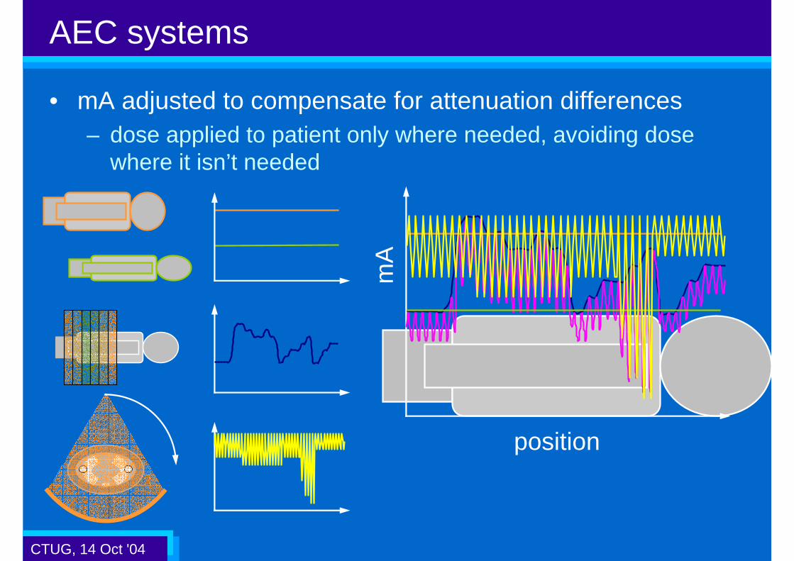
AEC systems
• mA adjusted to compensate for attenuation differences– dose applied to patient only where needed, avoiding dose
where it isn’t needed
mA
position
CTUG, 14 Oct '04
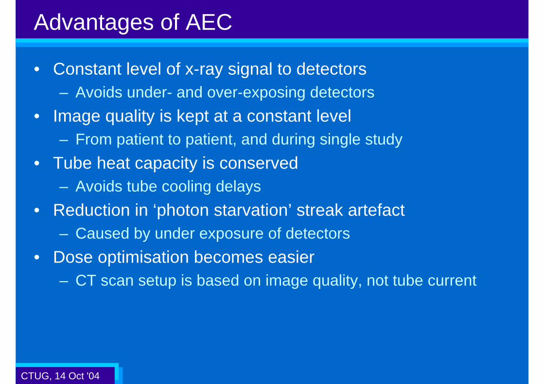
Advantages of AEC
• Constant level of x-ray signal to detectors– Avoids under- and over-exposing detectors
• Image quality is kept at a constant level– From patient to patient, and during single study
• Tube heat capacity is conserved– Avoids tube cooling delays
• Reduction in ‘photon starvation’ streak artefact– Caused by under exposure of detectors
• Dose optimisation becomes easier– CT scan setup is based on image quality, not tube current

CTUG, 14 Oct '04
• AEC systems available on multi-slice systems are applied at one or more levels:
*GE LightSpeed Pro16 only**Siemens Sensation 10/16 upwards only
Current systems
Z-axis AEC
SUREExposure / Real EC
CAREDose 4D**
DoseRight ACS
Auto mA
Patient size AEC
DoseRight DOMPhilips
CareDoseSiemens
Toshiba
SmartmA*GE
mA modulation
CTUG, 14 Oct '04
Methods to set AEC exposure level
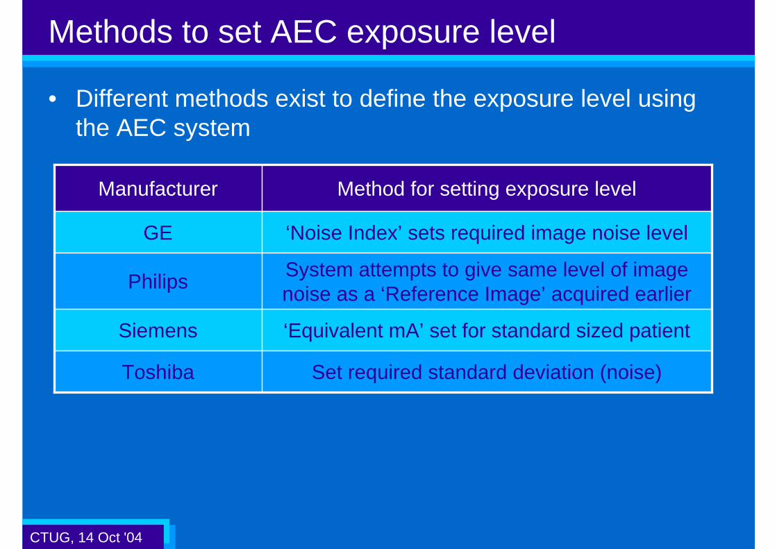
• Different methods exist to define the exposure level using the AEC system
System attempts to give same level of image noise as a ‘Reference Image’ acquired earlier
Philips
‘Equivalent mA’ set for standard sized patientSiemens
Set required standard deviation (noise)Toshiba
‘Noise Index’ sets required image noise levelGE
Method for setting exposure levelManufacturer
CTUG, 14 Oct '04
ImPACT phantom
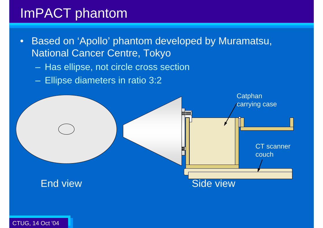
• Based on ‘Apollo’ phantom developed by Muramatsu, National Cancer Centre, Tokyo– Has ellipse, not circle cross section– Ellipse diameters in ratio 3:2
End view Side view
CT scanner couch
Catphan carrying case

CTUG, 14 Oct '04
ImPACT phantom
• Images along length of phantom (AEC off)

CTUG, 14 Oct '04
Coronal view Sagittal view
ImPACT phantom
z-axisAEC off
z-axis AEC on
Noise increases
Constant noise

CTUG, 14 Oct '04
Scan protocol
• Standard conditions:– 120 kV, approx 200 mA, 1 s or less rotation time, – wide collimation e.g. 20 mm, 5 mm slice, 45 cm reconstruction
field of view
• Scan along phantom with AEC off and on– If possible select different features of AEC separately
• Look at effect of:– Exposure level – change desired standard deviation or
reference mA– kV– Axial and helical scanning– Helical pitch and direction of couch movement
• Store DICOM images on CD

CTUG, 14 Oct '04
Image analysis
• mA information retrieved from DICOM files• Standard deviation (SD) and average CT number calculated
at centre and edge of imageusing automatic analysis tool
• Region of Interest (ROI) size2000 mm2
• Results analysed using Excel

CTUG, 14 Oct '04
Results from testing
• Testing takes 1-2 hours.– Delays for tube cooling can be long
• Aims of each AEC system are slightly different, so it is difficult to compare results
• In general, all systems successfully achieved their aims
• Following slides show a selection of the results so far, much more data has been gathered

CTUG, 14 Oct '04
Results: GE
0
5
10
15
20
25
30
35
50 100 150 200 250 300
AP phantom diameter (mm)
Mea
sure
d S
D
Auto mA OFF
NI = 5
NI = 10
NI = 15
NI = 20
27.310-28020
18.010-50015
11.010-78310
10-783
200
mA
4.45
-AEC off
Mean SD
Noise Index
CTUG, 14 Oct '04
Results: GE
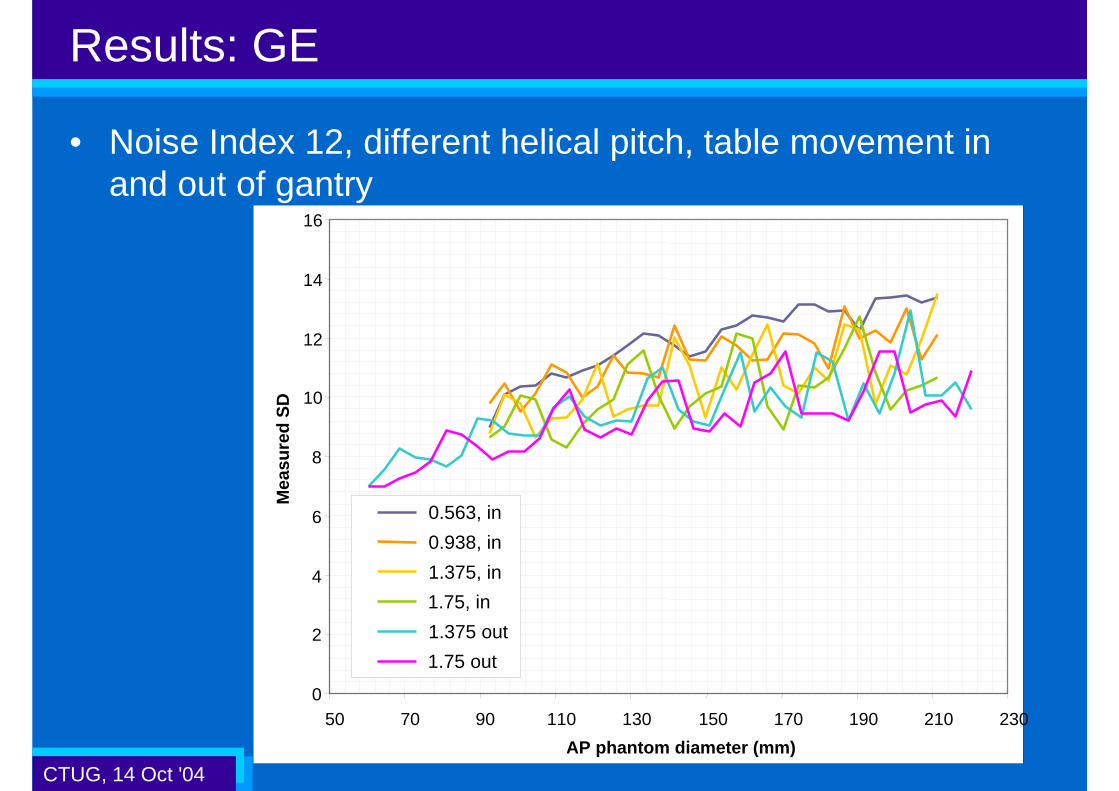
• Noise Index 12, different helical pitch, table movement in and out of gantry
0
2
4
6
8
10
12
14
16
50 70 90 110 130 150 170 190 210 230
AP phantom diameter (mm)
Mea
sure
d S
D
0.563, in
0.938, in
1.375, in
1.75, in
1.375 out
1.75 out

CTUG, 14 Oct '04
Results: GE
Axial
0
100
200
300
400
500
600
700
800
900
50 100 150 200 250 300
AP phantom diameter (mm)
Tu
be
curr
ent
(mA
)
Auto mA OFF
NI = 5
NI = 10
NI = 15
NI = 20
Axial
10
100
1000
50 100 150 200 250 300
AP phantom diameter (mm)
Tu
be
curr
ent
(mA
)
Auto mA OFF
NI = 5
NI = 10
NI = 15
NI = 20
Helical 10
100
1000
50 100 150 200 250
AP phantom diameter (mm)
Tu
be
curr
ent
(mA
)
0.563, in
0.938, in
1.375, in
1.75, in
1.375 out
1.75 out

CTUG, 14 Oct '04
Results: GE
• Different kVs, Noise Index 10
73
105
179
451
mA (Smart mA off)
10.9100
10.5120
10.7140
10.680
Measured SDkV
CTUG, 14 Oct '04
Results: Philips
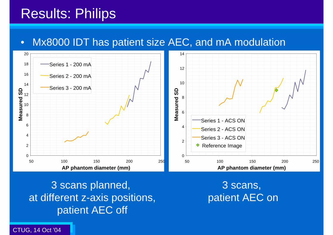
• Mx8000 IDT has patient size AEC, and mA modulation
3 scans planned, at different z-axis positions,
patient AEC off
0
2
4
6
8
10
12
14
16
18
20
50 100 150 200 250
AP phantom diameter (mm)
Mea
sure
d S
D
Series 1 - 200 mA
Series 2 - 200 mA
Series 3 - 200 mA
3 scans, patient AEC on
0
2
4
6
8
10
12
14
50 100 150 200 250
AP phantom diameter (mm)
Mea
sure
d S
D
Reference Image
Series 1 - ACS ON
Series 2 - ACS ON
Series 3 - ACS ON

CTUG, 14 Oct '04
Results: Siemens
• CAREDose – only mA modulation tested• With CAREDose on, effective mA, and therefore dose
decreases (noise increases)
0
2
4
6
8
10
12
14
16
18
50 100 150 200 250AP phantom diameter (mm)
Mea
sure
d S
D
CAREDose on
CAREDose off

CTUG, 14 Oct '04
Results: Siemens
• Set mA = 200• mA modulation is greatest at wide end
of phantom – lower mean mA at wide end• Improvements of up to 9% in noise and
dose (9% lower noise for same dose).• Greater improvements would be seen
in a shoulder shaped phantom
0.91
0.93
Relative SD
12.2
SD -CAREDose
134
mean mA / mA
50.0
13.0
SD constant mA
47.2120

CTUG, 14 Oct '04
Results: Toshiba
• Data from RealEC on Aquilion 16
0
5
10
15
20
25
30
50 100 150 200 250 300
AP phantom diameter (mm)
Mea
sure
d S
DFixed mA
SD 5
SD 10
SD 12
SD 17

CTUG, 14 Oct '04
Future work plans
• Need to incorporate CAREDose 4D data:– Scanned last week, not yet fully analysed
• Could look at mA modulation systems in greater depth– Would require a less symmetrical phantom: our abdomen
phantom diameter is in ratio 3:2, shoulders are closer to 5:2
Abdomen Shoulder

CTUG, 14 Oct '04
Challenges for manufacturers and users
• Optimisation of scan protocols– AEC systems provide a method to define protocols in terms of
image quality, rather than dose level– Work required to ensure that radiologists are getting good
image quality, and patient doses are under control
• Standardisation of method to set exposure level– Currently, the user can choose noise index, reference mA,
reference image, required SD– A single method would aid comparison of scan protocols from
many scanners or scanning centres
• Education of users– AEC systems do not automatically lead to dose reduction –
correct definition of required IQ is important

CTUG, 14 Oct '04
Conclusions
• AEC systems offer potential benefits for everyone!– Radiologists: image quality consistent from patient to patient– Radiographers: setting image quality for different sized
patients is now much easier– Patients: potential for dose reduction, repeat exams less likely– Physicists: protocol optimisation is easier
• Users need to understand the systems– How does mA vary when changing slice thickness or kernel?
• The current systems work as intended, but there is opportunity to improve them further– A common method for defining exposure would be useful– Potential to vary scan times and kV automatically


![2016.09.07 Current challenges pesticide risk assessment · risk assessment = [effect + exposure] assessment Effect and exposure assessment goals are often not defined in a coherent](https://static.fdocuments.net/doc/165x107/5ed2d766efe33375000b2b17/20160907-current-challenges-pesticide-risk-assessment-risk-assessment-effect.jpg)