Assembly Language Programming - Electrical and - · PDF fileAssembly Language Programming...
53
Assembly Language Programming EE3376 1
Transcript of Assembly Language Programming - Electrical and - · PDF fileAssembly Language Programming...
Assembly Language Programming
EE3376
1
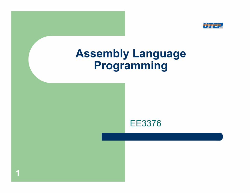
Moving Up Levels of Abstraction
Problems
Algorithms
Language
Machine (ISA) Architecture
Microarchitecture
Circuits
Devices Transistors
Logic gates, multiplexers, memory, etc.
MSP430 Architecture
Machine code
Assembly code
Adapted from notes from BYU ECE124 2
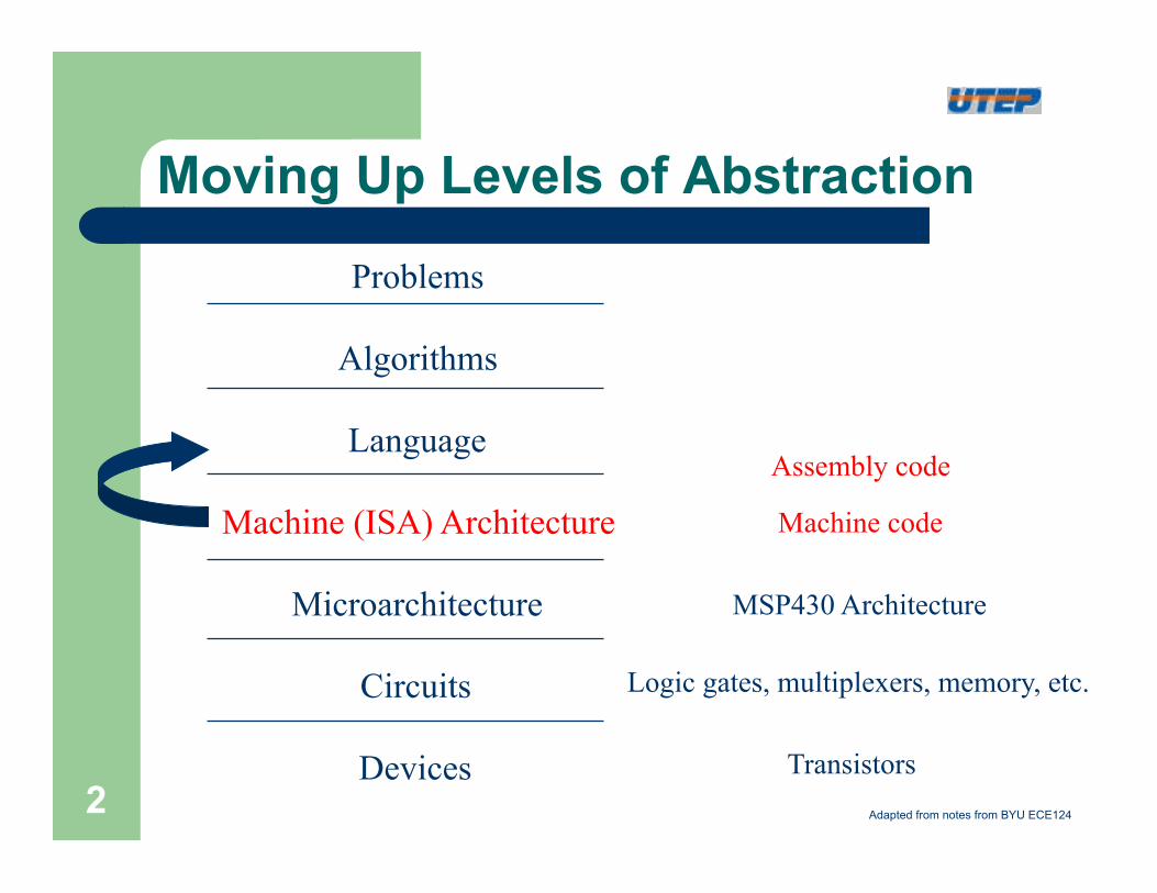
High Level vs. Assembly
l High Level Languages – More programmer friendly – More ISA independent – Each high-level statement translates to several
instructions in the ISA of the computer l Assembly Languages
– Lower level, closer to ISA – Very ISA-dependent – Each instruction specifies a single ISA instruction – Makes low level programming more user friendly – More efficient code
Adapted from notes from BYU ECE124 3
Assembler Syntax
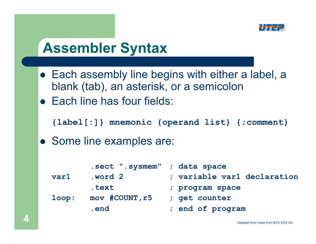
l Each assembly line begins with either a label, a blank (tab), an asterisk, or a semicolon
l Each line has four fields:
{label[:]} mnemonic {operand list} {;comment}
l Some line examples are:
.sect ".sysmem" ; data space var1 .word 2 ; variable var1 declaration .text ; program space loop: mov #COUNT,r5 ; get counter .end ; end of program
Adapted from notes from BYU ECE124 4
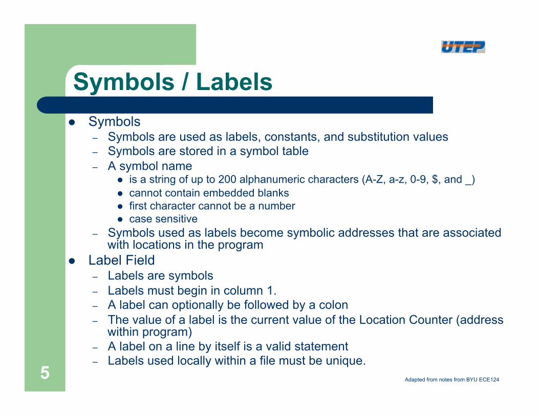
Symbols / Labels l Symbols
– Symbols are used as labels, constants, and substitution values – Symbols are stored in a symbol table – A symbol name
l is a string of up to 200 alphanumeric characters (A-Z, a-z, 0-9, $, and _) l cannot contain embedded blanks l first character cannot be a number l case sensitive
– Symbols used as labels become symbolic addresses that are associated with locations in the program
l Label Field – Labels are symbols – Labels must begin in column 1. – A label can optionally be followed by a colon – The value of a label is the current value of the Location Counter (address
within program) – A label on a line by itself is a valid statement – Labels used locally within a file must be unique.
Adapted from notes from BYU ECE124 5
Mnemonics / Operands
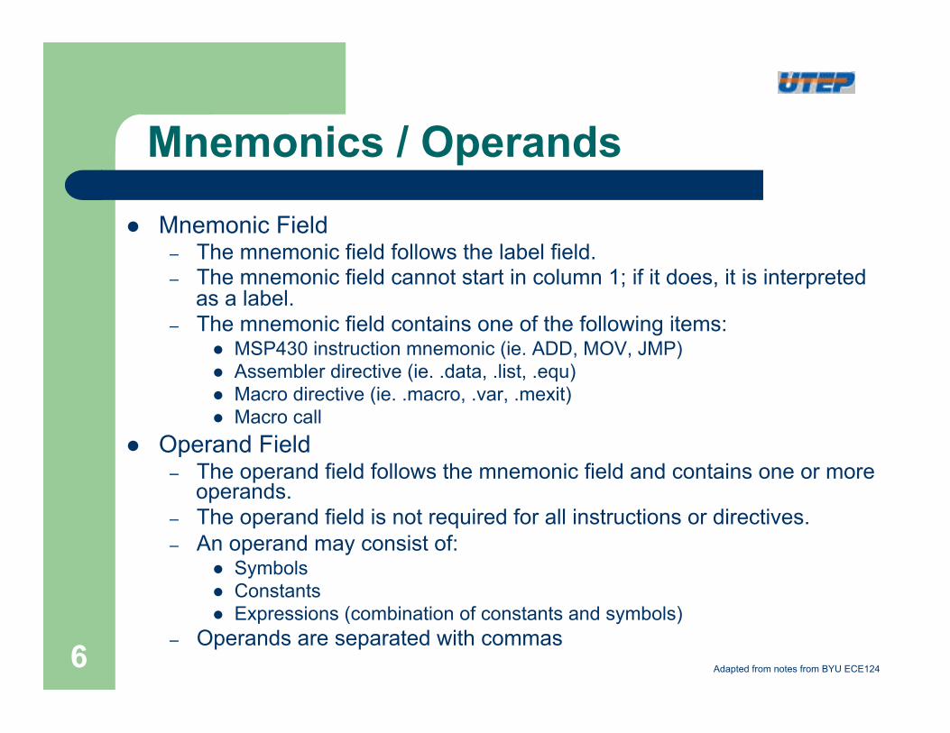
l Mnemonic Field – The mnemonic field follows the label field. – The mnemonic field cannot start in column 1; if it does, it is interpreted
as a label. – The mnemonic field contains one of the following items:
l MSP430 instruction mnemonic (ie. ADD, MOV, JMP) l Assembler directive (ie. .data, .list, .equ) l Macro directive (ie. .macro, .var, .mexit) l Macro call
l Operand Field – The operand field follows the mnemonic field and contains one or more
operands. – The operand field is not required for all instructions or directives. – An operand may consist of:
l Symbols l Constants l Expressions (combination of constants and symbols)
– Operands are separated with commas Adapted from notes from BYU ECE124 6
Assembler Directives
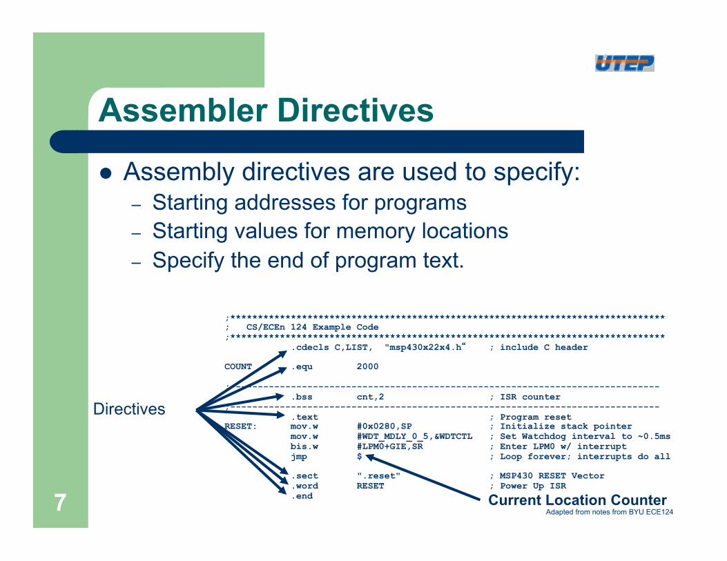
l Assembly directives are used to specify: – Starting addresses for programs – Starting values for memory locations – Specify the end of program text.
;******************************************************************************* ; CS/ECEn 124 Example Code ;*******************************************************************************
.cdecls C,LIST, "msp430x22x4.h“ ; include C header COUNT .equ 2000 ;------------------------------------------------------------------------------
.bss cnt,2 ; ISR counter ;------------------------------------------------------------------------------ .text ; Program reset RESET: mov.w #0x0280,SP ; Initialize stack pointer
mov.w #WDT_MDLY_0_5,&WDTCTL ; Set Watchdog interval to ~0.5ms bis.w #LPM0+GIE,SR ; Enter LPM0 w/ interrupt jmp $ ; Loop forever; interrupts do all
.sect ".reset" ; MSP430 RESET Vector .word RESET ; Power Up ISR .end
Directives
Current Location Counter Adapted from notes from BYU ECE124 7
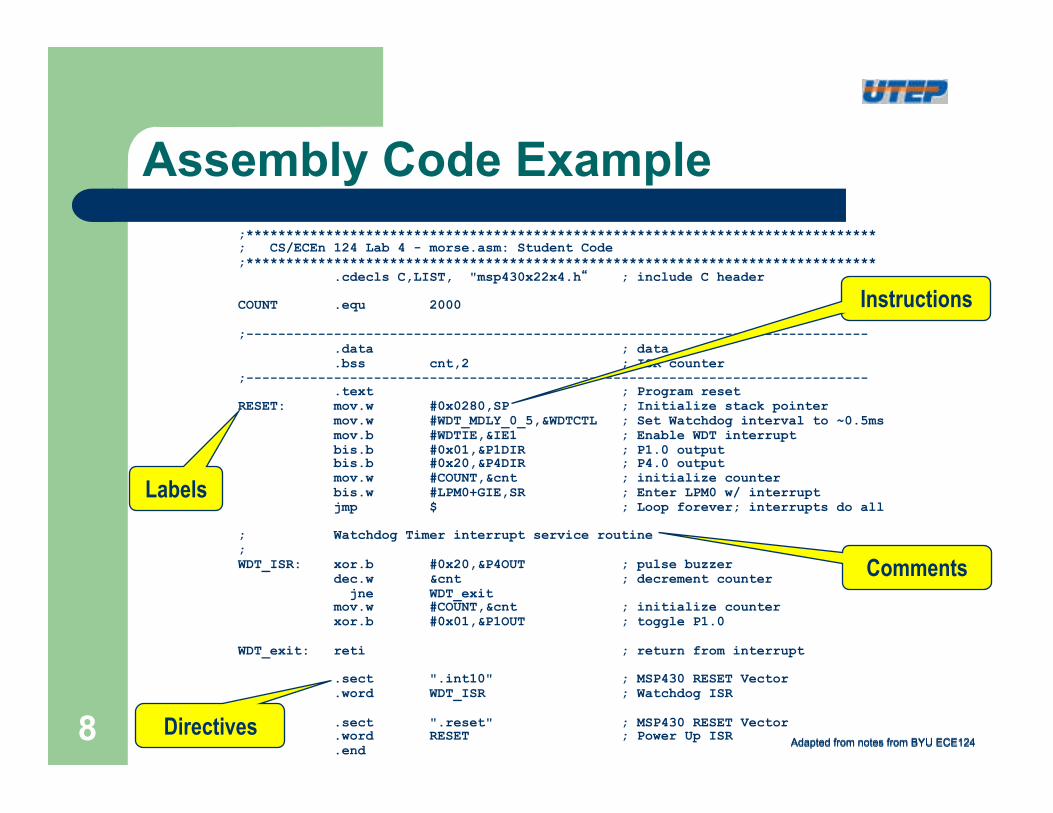
Assembly Code Example ;******************************************************************************* ; CS/ECEn 124 Lab 4 - morse.asm: Student Code ;*******************************************************************************
.cdecls C,LIST, "msp430x22x4.h“ ; include C header COUNT .equ 2000 ;------------------------------------------------------------------------------ .data ; data
.bss cnt,2 ; ISR counter ;------------------------------------------------------------------------------ .text ; Program reset RESET: mov.w #0x0280,SP ; Initialize stack pointer
mov.w #WDT_MDLY_0_5,&WDTCTL ; Set Watchdog interval to ~0.5ms mov.b #WDTIE,&IE1 ; Enable WDT interrupt bis.b #0x01,&P1DIR ; P1.0 output bis.b #0x20,&P4DIR ; P4.0 output mov.w #COUNT,&cnt ; initialize counter bis.w #LPM0+GIE,SR ; Enter LPM0 w/ interrupt jmp $ ; Loop forever; interrupts do all
; Watchdog Timer interrupt service routine ; WDT_ISR: xor.b #0x20,&P4OUT ; pulse buzzer
dec.w &cnt ; decrement counter jne WDT_exit mov.w #COUNT,&cnt ; initialize counter xor.b #0x01,&P1OUT ; toggle P1.0
WDT_exit: reti ; return from interrupt
.sect ".int10" ; MSP430 RESET Vector .word WDT_ISR ; Watchdog ISR
.sect ".reset" ; MSP430 RESET Vector .word RESET ; Power Up ISR .end
Labels
Instructions
Comments
Directives Adapted from notes from BYU ECE124 Adapted from notes from BYU ECE124 8
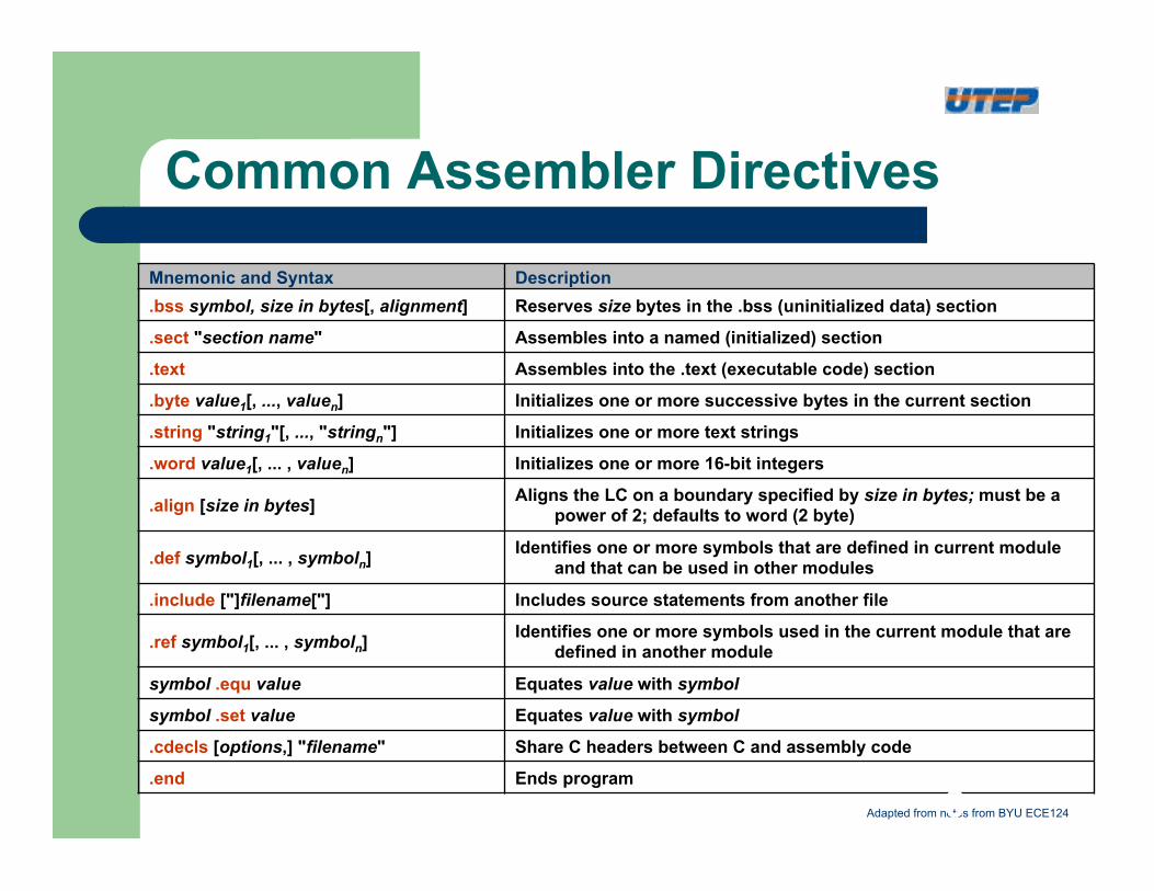
Common Assembler Directives
Mnemonic and Syntax Description .bss symbol, size in bytes[, alignment] Reserves size bytes in the .bss (uninitialized data) section
.sect "section name" Assembles into a named (initialized) section
.text Assembles into the .text (executable code) section
.byte value1[, ..., valuen] Initializes one or more successive bytes in the current section
.string "string1"[, ..., "stringn"] Initializes one or more text strings
.word value1[, ... , valuen] Initializes one or more 16-bit integers
.align [size in bytes] Aligns the LC on a boundary specified by size in bytes; must be a power of 2; defaults to word (2 byte)
.def symbol1[, ... , symboln] Identifies one or more symbols that are defined in current module and that can be used in other modules
.include ["]filename["] Includes source statements from another file
.ref symbol1[, ... , symboln] Identifies one or more symbols used in the current module that are defined in another module
symbol .equ value Equates value with symbol
symbol .set value Equates value with symbol
.cdecls [options,] "filename" Share C headers between C and assembly code
.end Ends program
Adapted from notes from BYU ECE124 9
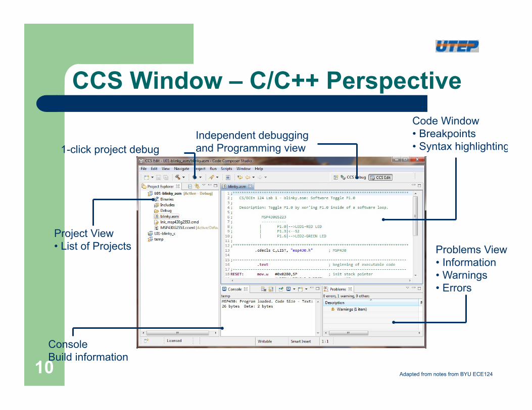
CCS Window – C/C++ Perspective
Independent debugging and Programming view 1-click project debug
Project View • List of Projects
Code Window • Breakpoints • Syntax highlighting
Console Build information
Problems View • Information • Warnings • Errors
Adapted from notes from BYU ECE124 10
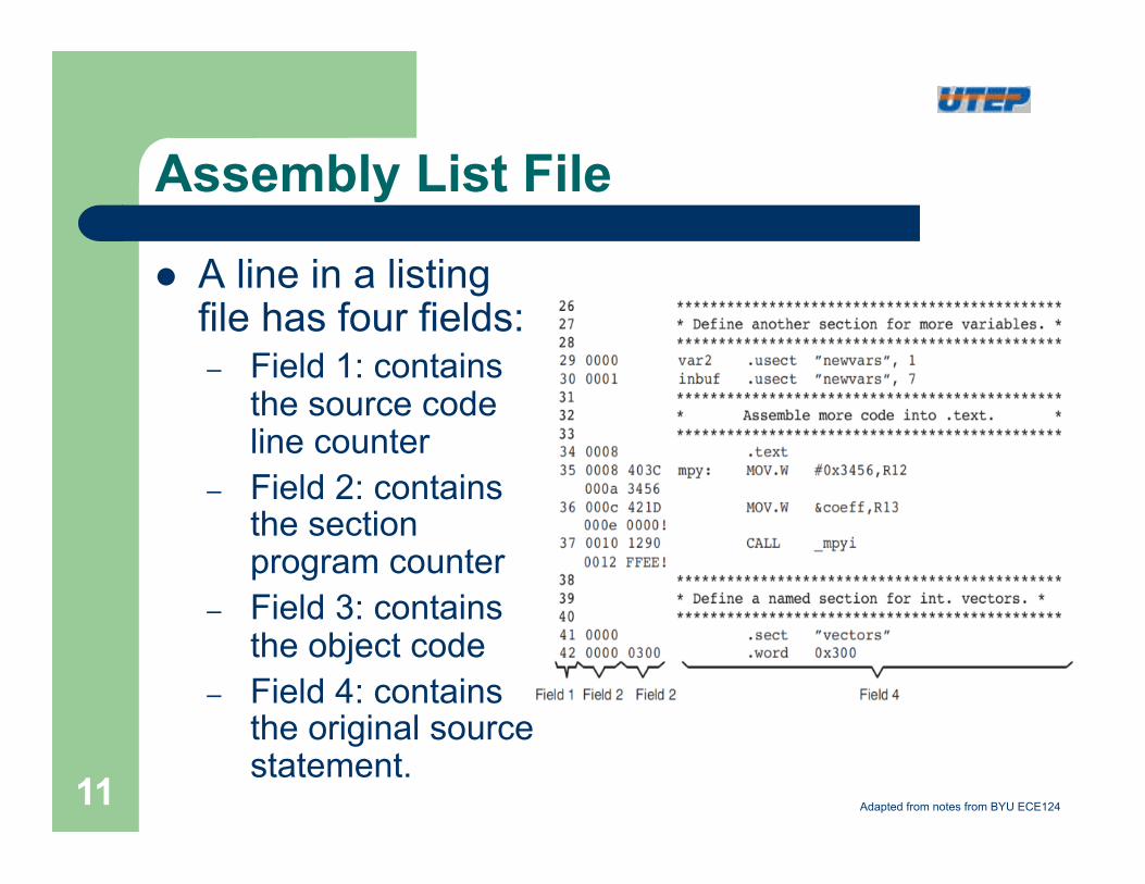
Assembly List File
l A line in a listing file has four fields: – Field 1: contains
the source code line counter
– Field 2: contains the section program counter
– Field 3: contains the object code
– Field 4: contains the original source statement.
Adapted from notes from BYU ECE124 11
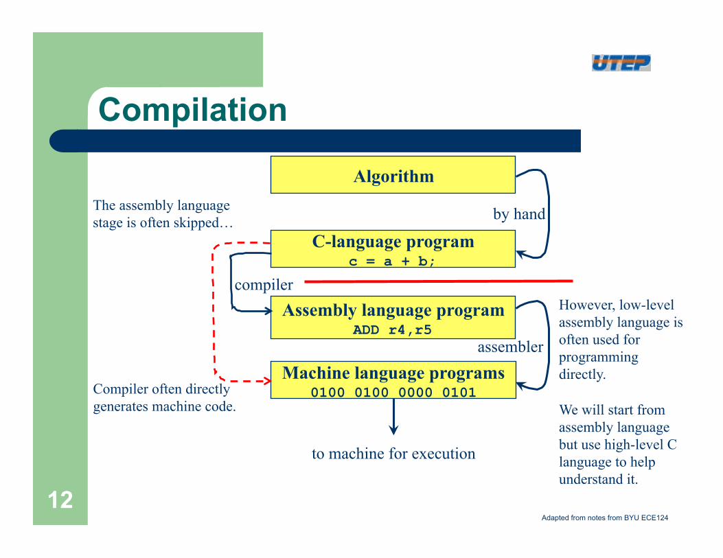
Compilation
Algorithm
C-language program c = a + b;
by hand
Machine language programs 0100 0100 0000 0101
assembler
Assembly language program ADD r4,r5
compiler
to machine for execution
However, low-level assembly language is often used for programming directly. We will start from assembly language but use high-level C language to help understand it.
Compiler often directly generates machine code.
The assembly language stage is often skipped…
Adapted from notes from BYU ECE124
12
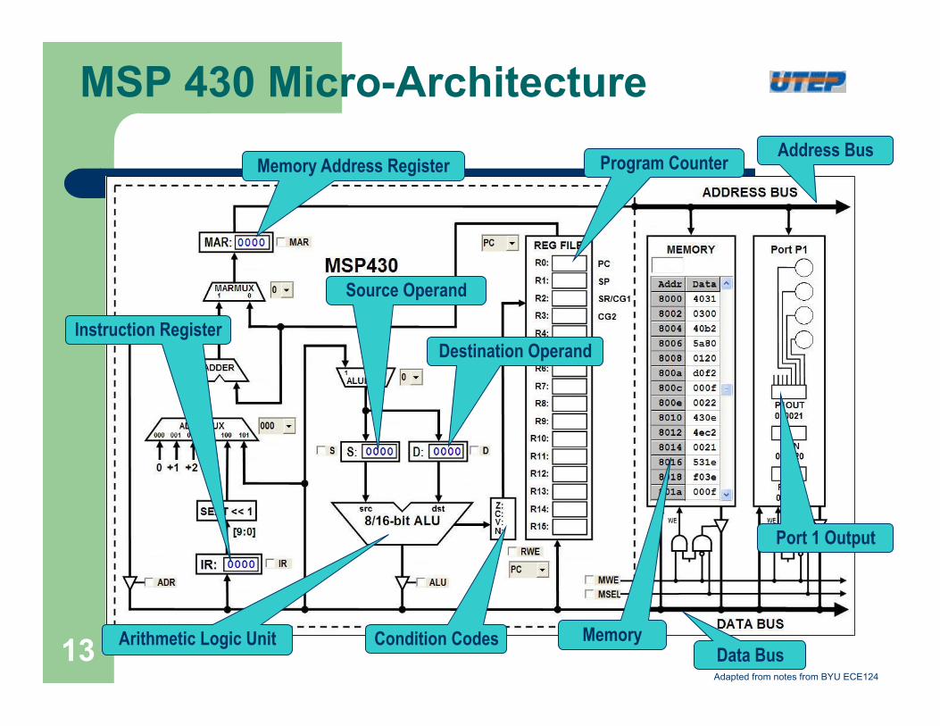
MSP 430 Micro-Architecture
Memory Address Register
Arithmetic Logic Unit
Program Counter Address Bus
Data Bus Condition Codes Memory
Port 1 Output
Instruction Register
Source Operand
Destination Operand
Adapted from notes from BYU ECE124
13
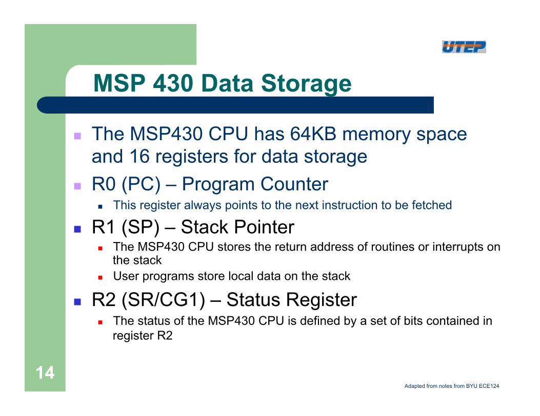
MSP 430 Data Storage
n The MSP430 CPU has 64KB memory space and 16 registers for data storage
n R0 (PC) – Program Counter n This register always points to the next instruction to be fetched
n R1 (SP) – Stack Pointer n The MSP430 CPU stores the return address of routines or interrupts on
the stack n User programs store local data on the stack
n R2 (SR/CG1) – Status Register n The status of the MSP430 CPU is defined by a set of bits contained in
register R2
Adapted from notes from BYU ECE124
14
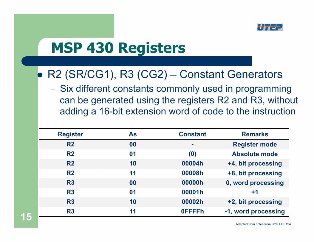
l R2 (SR/CG1), R3 (CG2) – Constant Generators – Six different constants commonly used in programming
can be generated using the registers R2 and R3, without adding a 16-bit extension word of code to the instruction
Register As Constant Remarks R2 00 - Register mode R2 01 (0) Absolute mode R2 10 00004h +4, bit processing R2 11 00008h +8, bit processing R3 00 00000h 0, word processing R3 01 00001h +1 R3 10 00002h +2, bit processing R3 11 0FFFFh -1, word processing
MSP 430 Registers
Adapted from notes from BYU ECE124 15
MSP 430 Registers
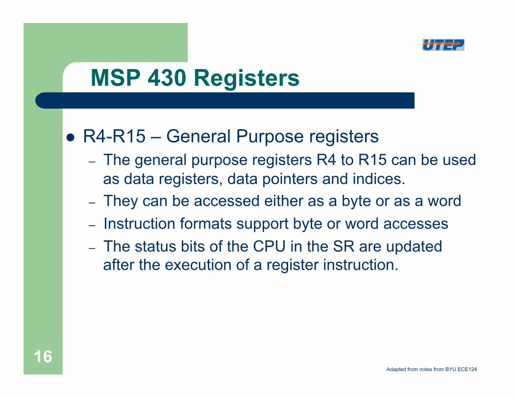
l R4-R15 – General Purpose registers – The general purpose registers R4 to R15 can be used
as data registers, data pointers and indices. – They can be accessed either as a byte or as a word – Instruction formats support byte or word accesses – The status bits of the CPU in the SR are updated
after the execution of a register instruction.
Adapted from notes from BYU ECE124
16
MSP430G2553 Memory Map
17
Format I: 12 Double Operand Instructions
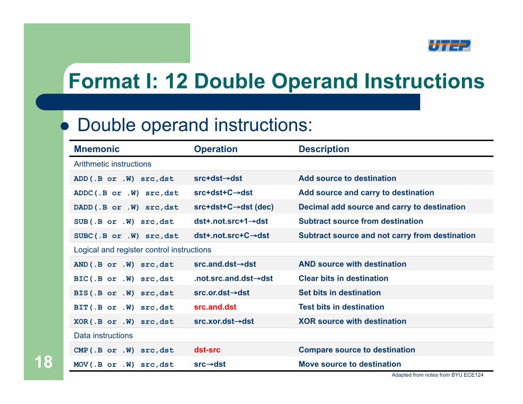
l Double operand instructions: Mnemonic Operation Description Arithmetic instructions ADD(.B or .W) src,dst src+dst→dst Add source to destination ADDC(.B or .W) src,dst src+dst+C→dst Add source and carry to destination DADD(.B or .W) src,dst src+dst+C→dst (dec) Decimal add source and carry to destination SUB(.B or .W) src,dst dst+.not.src+1→dst Subtract source from destination SUBC(.B or .W) src,dst dst+.not.src+C→dst Subtract source and not carry from destination Logical and register control instructions AND(.B or .W) src,dst src.and.dst→dst AND source with destination BIC(.B or .W) src,dst .not.src.and.dst→dst Clear bits in destination BIS(.B or .W) src,dst src.or.dst→dst Set bits in destination BIT(.B or .W) src,dst src.and.dst Test bits in destination XOR(.B or .W) src,dst src.xor.dst→dst XOR source with destination Data instructions CMP(.B or .W) src,dst dst-src Compare source to destination MOV(.B or .W) src,dst src→dst Move source to destination
Adapted from notes from BYU ECE124
18
Examples
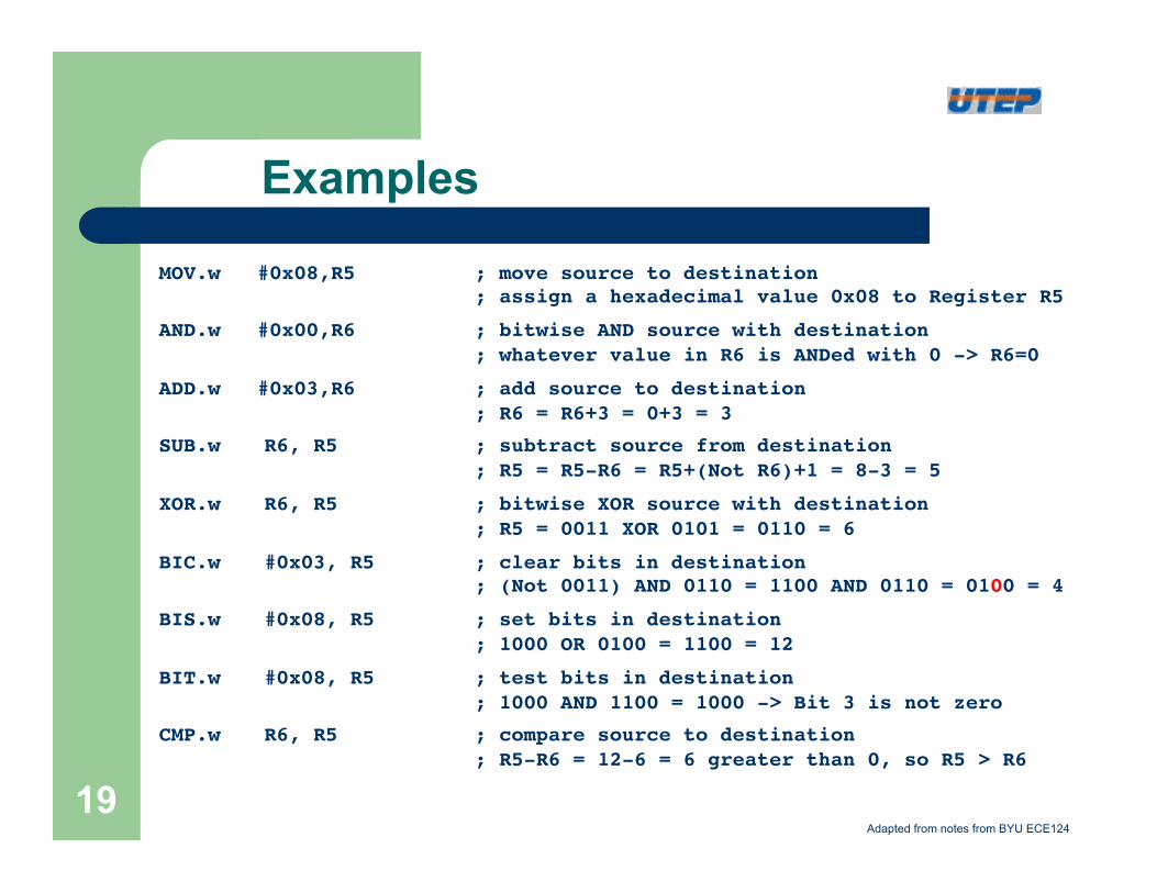
MOV.w #0x08,R5! !; move source to destination !! ! !; assign a hexadecimal value 0x08 to Register R5 !
AND.w #0x00,R6! !; bitwise AND source with destination !! ! !; whatever value in R6 is ANDed with 0 -> R6=0!
ADD.w #0x03,R6! !; add source to destination !! ! !; R6 = R6+3 = 0+3 = 3!
SUB.w !R6, R5 ! !; subtract source from destination!! ! !; R5 = R5-R6 = R5+(Not R6)+1 = 8-3 = 5!
XOR.w !R6, R5 ! !; bitwise XOR source with destination !! ! !; R5 = 0011 XOR 0101 = 0110 = 6!
BIC.w !#0x03, R5 !; clear bits in destination!! ! !; (Not 0011) AND 0110 = 1100 AND 0110 = 0100 = 4!
BIS.w !#0x08, R5 !; set bits in destination!! ! !; 1000 OR 0100 = 1100 = 12!
BIT.w !#0x08, R5 !; test bits in destination!! ! !; 1000 AND 1100 = 1000 -> Bit 3 is not zero!
CMP.w !R6, R5 ! !; compare source to destination!! ! !; R5-R6 = 12-6 = 6 greater than 0, so R5 > R6!
Adapted from notes from BYU ECE124
19
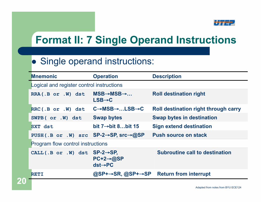
Format II: 7 Single Operand Instructions
l Single operand instructions: Mnemonic Operation Description Logical and register control instructions RRA(.B or .W) dst MSB→MSB→…
LSB→C Roll destination right
RRC(.B or .W) dst C→MSB→…LSB→C Roll destination right through carry SWPB( or .W) dst Swap bytes Swap bytes in destination SXT dst bit 7→bit 8…bit 15 Sign extend destination PUSH(.B or .W) src SP-2→SP, src→@SP Push source on stack Program flow control instructions CALL(.B or .W) dst SP-2→SP,
PC+2→@SP dst→PC
Subroutine call to destination
RETI @SP+→SR, @SP+→SP Return from interrupt
Adapted from notes from BYU ECE124
20
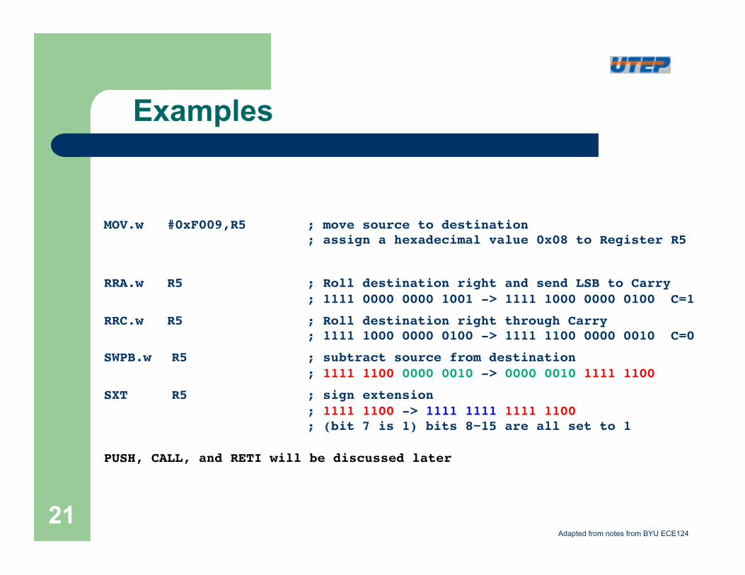
Examples
MOV.w #0xF009,R5 !; move source to destination !! ! !; assign a hexadecimal value 0x08 to Register R5 !
!
RRA.w R5 ! !; Roll destination right and send LSB to Carry!! ! !; 1111 0000 0000 1001 -> 1111 1000 0000 0100 C=1 !
RRC.w R5 ! !; Roll destination right through Carry!! ! !; 1111 1000 0000 0100 -> 1111 1100 0000 0010 C=0 !
SWPB.w !R5 ! !; subtract source from destination!! ! !; 1111 1100 0000 0010 -> 0000 0010 1111 1100 !
SXT !R5 ! !; sign extension!! ! !; 1111 1100 -> 1111 1111 1111 1100 !! ! !; (bit 7 is 1) bits 8~15 are all set to 1!
!PUSH, CALL, and RETI will be discussed later !
Adapted from notes from BYU ECE124
21
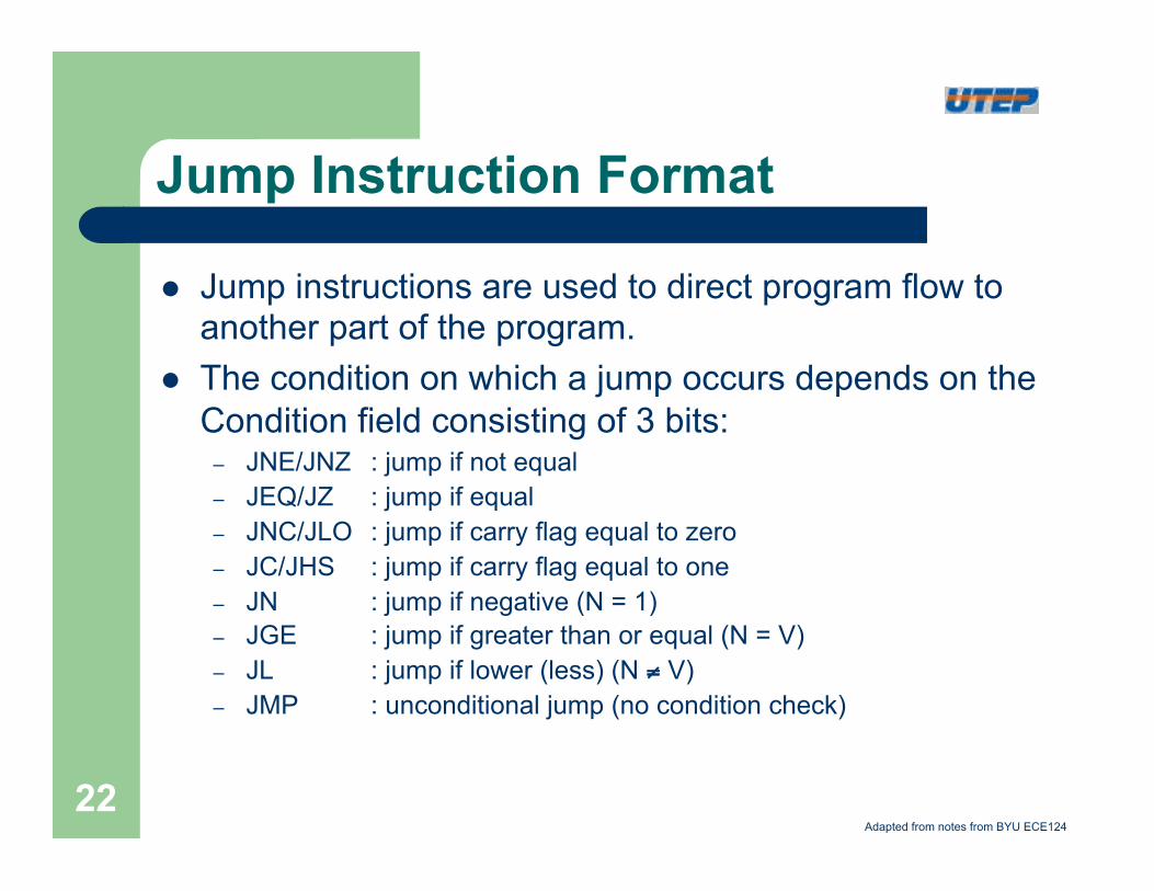
Jump Instruction Format
l Jump instructions are used to direct program flow to another part of the program.
l The condition on which a jump occurs depends on the Condition field consisting of 3 bits:
– JNE/JNZ : jump if not equal – JEQ/JZ : jump if equal – JNC/JLO : jump if carry flag equal to zero – JC/JHS : jump if carry flag equal to one – JN : jump if negative (N = 1) – JGE : jump if greater than or equal (N = V) – JL : jump if lower (less) (N ≠ V) – JMP : unconditional jump (no condition check)
Adapted from notes from BYU ECE124
22
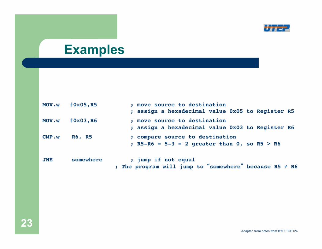
Examples
MOV.w #0x05,R5! !; move source to destination !! ! !; assign a hexadecimal value 0x05 to Register R5 !
MOV.w #0x03,R6! !; move source to destination !! ! !; assign a hexadecimal value 0x03 to Register R6 !
CMP.w !R6, R5 ! !; compare source to destination!! ! !; R5-R6 = 5-3 = 2 greater than 0, so R5 > R6!
!
JNE !somewhere !; jump if not equal!! ! ; The program will jump to “somewhere” because R5 ≠ R6!
Adapted from notes from BYU ECE124
23
Emulated Instructions
l In addition to the 27 instructions of the CPU there are 24 emulated instructions
l The CPU coding is unique l The emulated instructions make reading and
writing code easier, but do not have their own op-codes
l Emulated instructions are replaced automatically by CPU instructions by the assembler
l There are no penalties for using emulated instructions.
Adapted from notes from BYU ECE124
24
Emulated Instructions
Mnemonic Operation Emulation Description
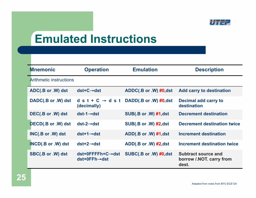
Arithmetic instructions
ADC(.B or .W) dst dst+C→dst ADDC(.B or .W) #0,dst Add carry to destination
DADC(.B or .W) dst d s t + C → d s t (decimally)
DADD(.B or .W) #0,dst Decimal add carry to destination
DEC(.B or .W) dst dst-1→dst SUB(.B or .W) #1,dst Decrement destination
DECD(.B or .W) dst dst-2→dst SUB(.B or .W) #2,dst Decrement destination twice
INC(.B or .W) dst dst+1→dst ADD(.B or .W) #1,dst Increment destination
INCD(.B or .W) dst dst+2→dst ADD(.B or .W) #2,dst Increment destination twice
SBC(.B or .W) dst dst+0FFFFh+C→dst dst+0FFh→dst
SUBC(.B or .W) #0,dst Subtract source and borrow /.NOT. carry from dest.
Adapted from notes from BYU ECE124
25
Emulated Instructions
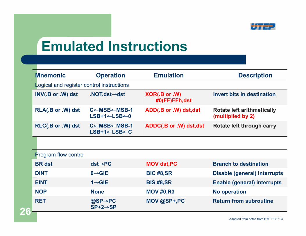
Mnemonic Operation Emulation Description Logical and register control instructions INV(.B or .W) dst .NOT.dst→dst XOR(.B or .W)
#0(FF)FFh,dst Invert bits in destination
RLA(.B or .W) dst C←MSB←MSB-1 LSB+1←LSB←0
ADD(.B or .W) dst,dst Rotate left arithmetically (multiplied by 2)
RLC(.B or .W) dst C←MSB←MSB-1 LSB+1←LSB←C
ADDC(.B or .W) dst,dst Rotate left through carry
Program flow control BR dst dst→PC MOV dst,PC Branch to destination DINT 0→GIE BIC #8,SR Disable (general) interrupts EINT 1→GIE BIS #8,SR Enable (general) interrupts NOP None MOV #0,R3 No operation RET @SP→PC
SP+2→SP MOV @SP+,PC Return from subroutine
Adapted from notes from BYU ECE124
26
Emulated Instructions
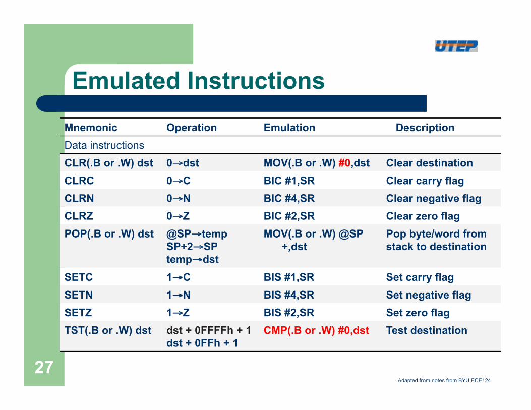
Mnemonic Operation Emulation Description Data instructions CLR(.B or .W) dst 0→dst MOV(.B or .W) #0,dst Clear destination CLRC 0→C BIC #1,SR Clear carry flag CLRN 0→N BIC #4,SR Clear negative flag CLRZ 0→Z BIC #2,SR Clear zero flag POP(.B or .W) dst @SP→temp
SP+2→SP temp→dst
MOV(.B or .W) @SP+,dst
Pop byte/word from stack to destination
SETC 1→C BIS #1,SR Set carry flag SETN 1→N BIS #4,SR Set negative flag SETZ 1→Z BIS #2,SR Set zero flag TST(.B or .W) dst dst + 0FFFFh + 1
dst + 0FFh + 1 CMP(.B or .W) #0,dst Test destination
Adapted from notes from BYU ECE124
27
Example: Emulated Instructions
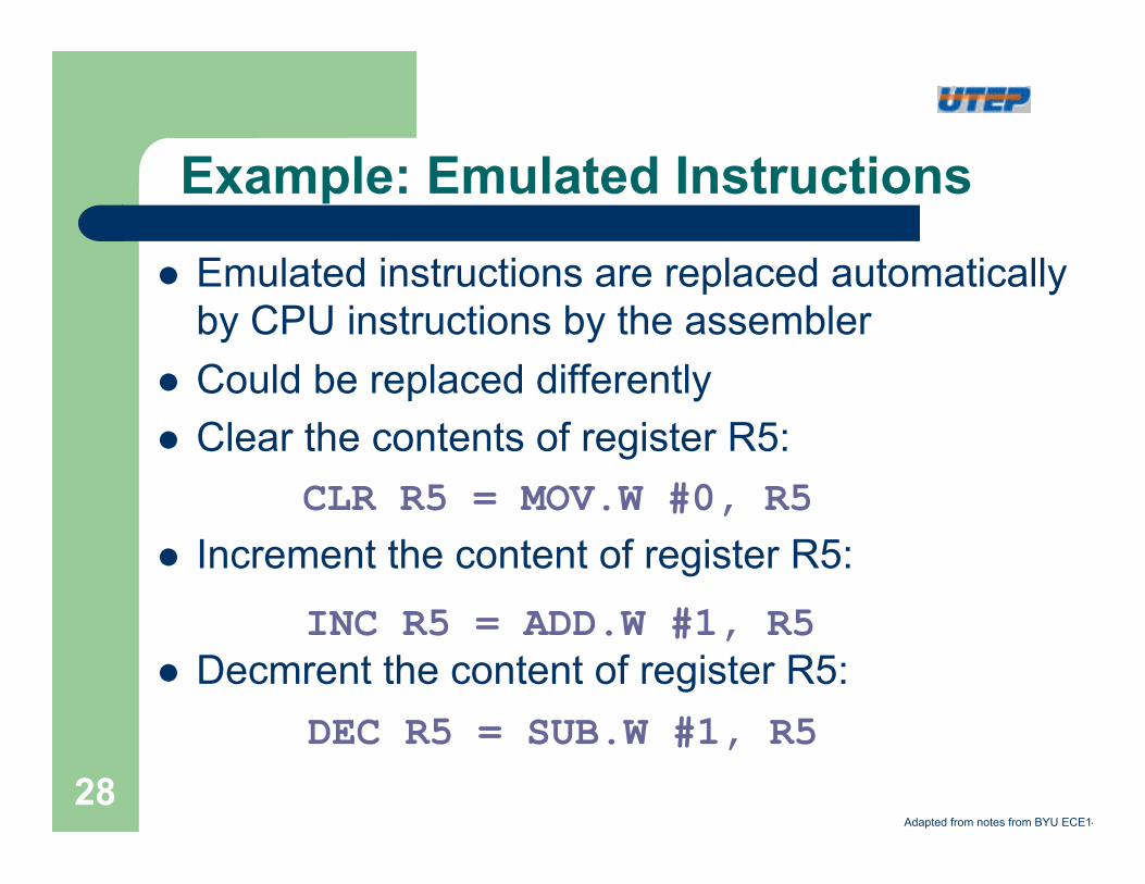
l Emulated instructions are replaced automatically by CPU instructions by the assembler
l Could be replaced differently l Clear the contents of register R5: l Increment the content of register R5:
l Decmrent the content of register R5:
CLR R5 = MOV.W #0, R5
INC R5 = ADD.W #1, R5
DEC R5 = SUB.W #1, R5
Adapted from notes from BYU ECE14
28
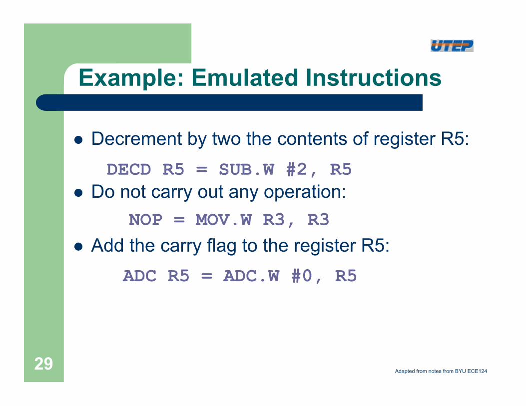
l Decrement by two the contents of register R5: l Do not carry out any operation:
l Add the carry flag to the register R5:
DECD R5 = SUB.W #2, R5
NOP = MOV.W R3, R3
ADC R5 = ADC.W #0, R5
Example: Emulated Instructions
Adapted from notes from BYU ECE124 29
Source Addressing Modes
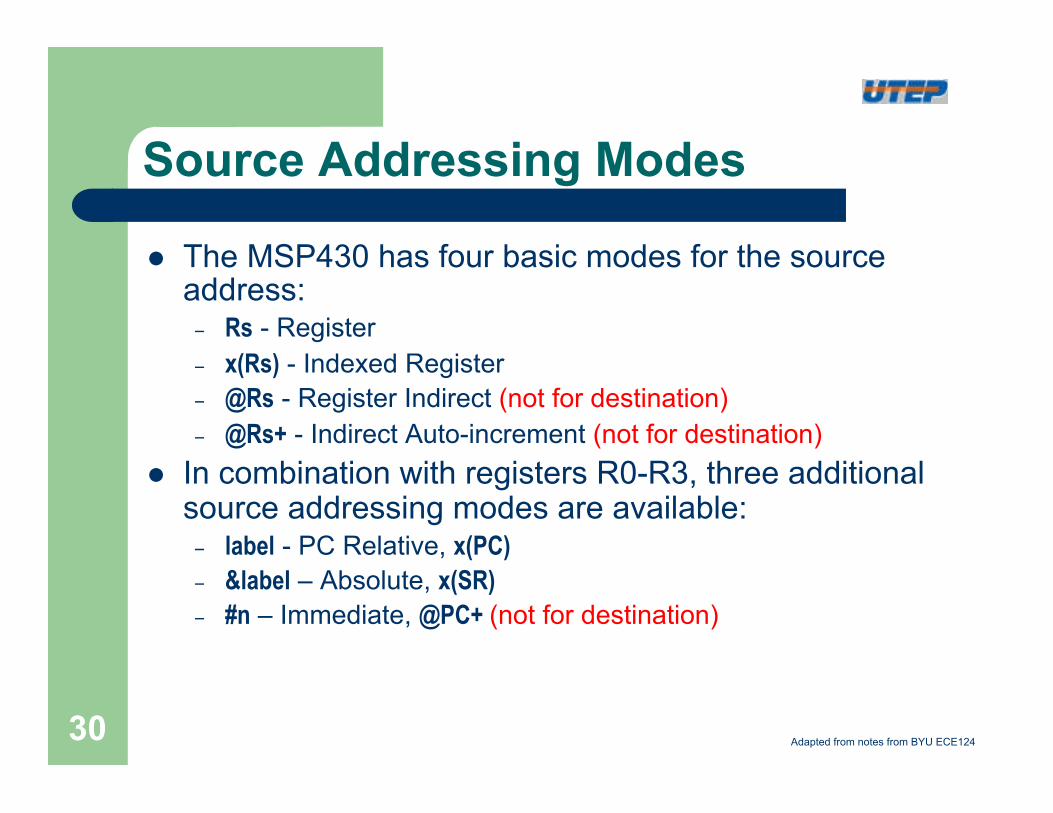
l The MSP430 has four basic modes for the source address:
– Rs - Register – x(Rs) - Indexed Register – @Rs - Register Indirect (not for destination) – @Rs+ - Indirect Auto-increment (not for destination)
l In combination with registers R0-R3, three additional source addressing modes are available:
– label - PC Relative, x(PC) – &label – Absolute, x(SR) – #n – Immediate, @PC+ (not for destination)
Adapted from notes from BYU ECE124 30
Destination Addressing Modes
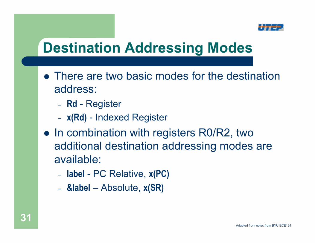
l There are two basic modes for the destination address:
– Rd - Register – x(Rd) - Indexed Register
l In combination with registers R0/R2, two additional destination addressing modes are available:
– label - PC Relative, x(PC) – &label – Absolute, x(SR)
Adapted from notes from BYU ECE124
31
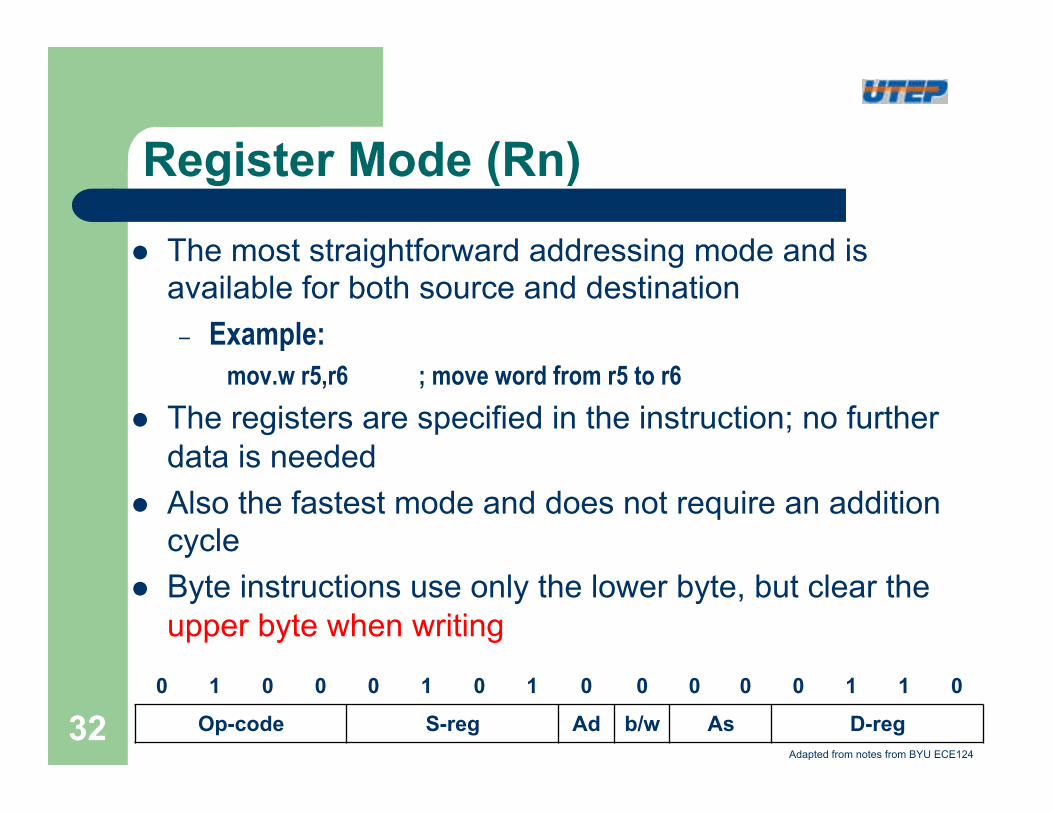
Register Mode (Rn)
l The most straightforward addressing mode and is available for both source and destination
– Example: mov.w r5,r6 ; move word from r5 to r6
l The registers are specified in the instruction; no further data is needed
l Also the fastest mode and does not require an addition cycle
l Byte instructions use only the lower byte, but clear the upper byte when writing
0 1 0 0 0 1 0 1 0 0 0 0 0 1 1 0
Op-code S-reg Ad b/w As D-reg Adapted from notes from BYU ECE124
32
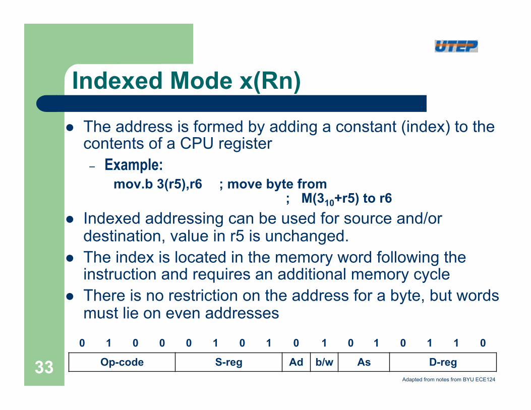
Indexed Mode x(Rn)
l The address is formed by adding a constant (index) to the contents of a CPU register
– Example: mov.b 3(r5),r6 ; move byte from
; M(310+r5) to r6 l Indexed addressing can be used for source and/or
destination, value in r5 is unchanged. l The index is located in the memory word following the
instruction and requires an additional memory cycle l There is no restriction on the address for a byte, but words
must lie on even addresses
0 1 0 0 0 1 0 1 0 1 0 1 0 1 1 0
Op-code S-reg Ad b/w As D-reg Adapted from notes from BYU ECE124
33
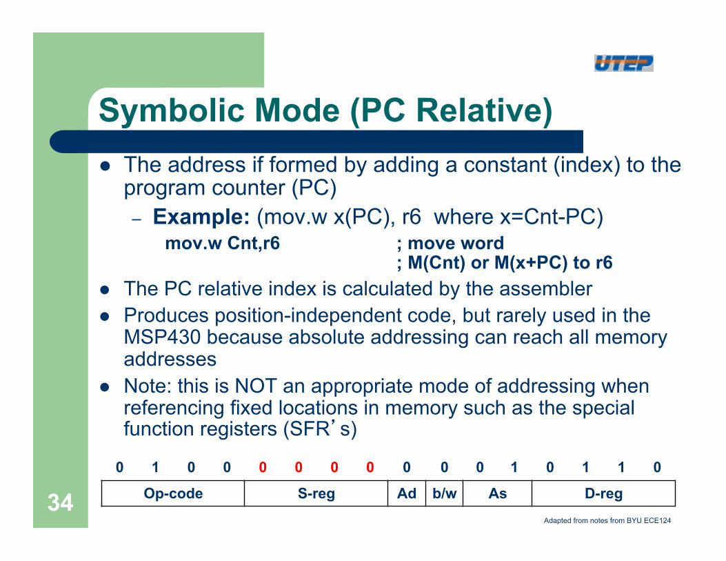
Symbolic Mode (PC Relative) l The address if formed by adding a constant (index) to the
program counter (PC) – Example: (mov.w x(PC), r6 where x=Cnt-PC)
mov.w Cnt,r6 ; move word ; M(Cnt) or M(x+PC) to r6
l The PC relative index is calculated by the assembler l Produces position-independent code, but rarely used in the
MSP430 because absolute addressing can reach all memory addresses
l Note: this is NOT an appropriate mode of addressing when referencing fixed locations in memory such as the special function registers (SFR’s)
0 1 0 0 0 0 0 0 0 0 0 1 0 1 1 0
Op-code S-reg Ad b/w As D-reg Adapted from notes from BYU ECE124
34
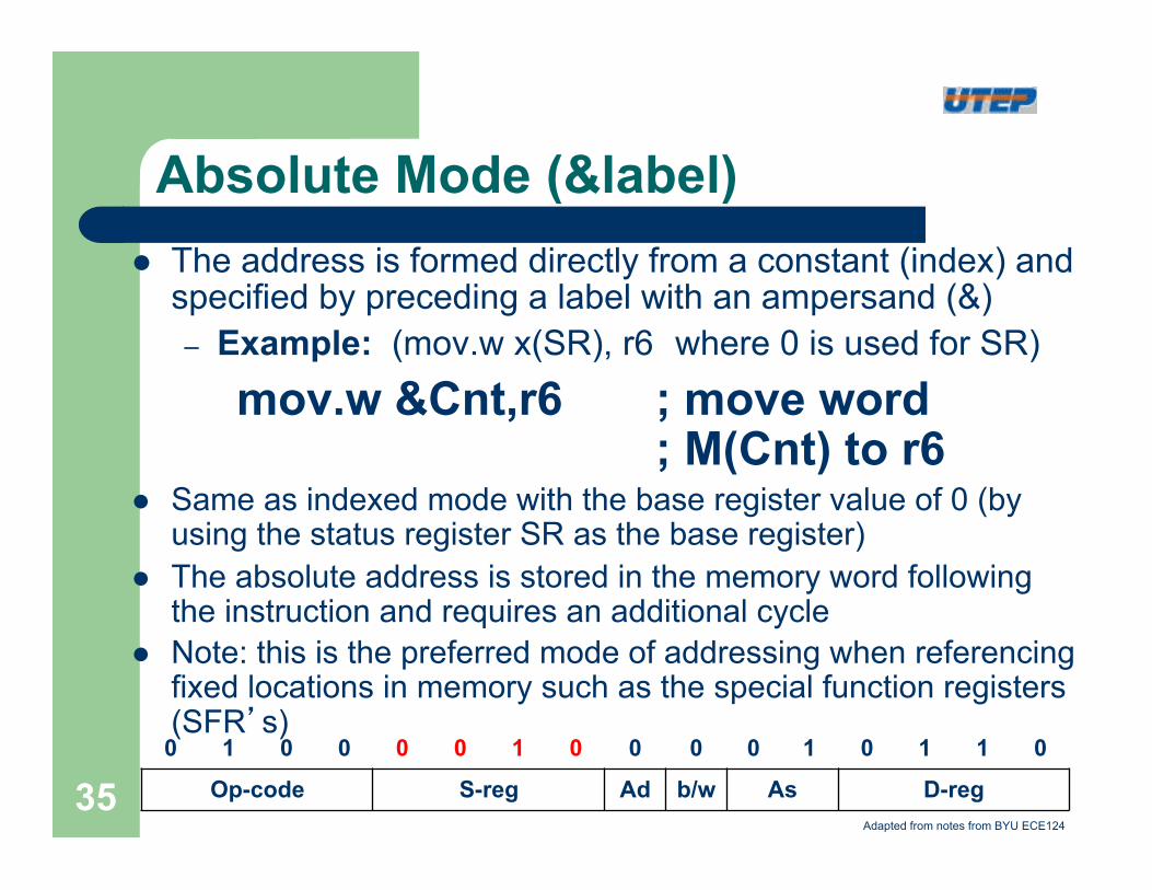
Absolute Mode (&label) l The address is formed directly from a constant (index) and
specified by preceding a label with an ampersand (&) – Example: (mov.w x(SR), r6 where 0 is used for SR)
mov.w &Cnt,r6 ; move word ; M(Cnt) to r6
l Same as indexed mode with the base register value of 0 (by using the status register SR as the base register)
l The absolute address is stored in the memory word following the instruction and requires an additional cycle
l Note: this is the preferred mode of addressing when referencing fixed locations in memory such as the special function registers (SFR’s)
0 1 0 0 0 0 1 0 0 0 0 1 0 1 1 0
Op-code S-reg Ad b/w As D-reg Adapted from notes from BYU ECE124
35
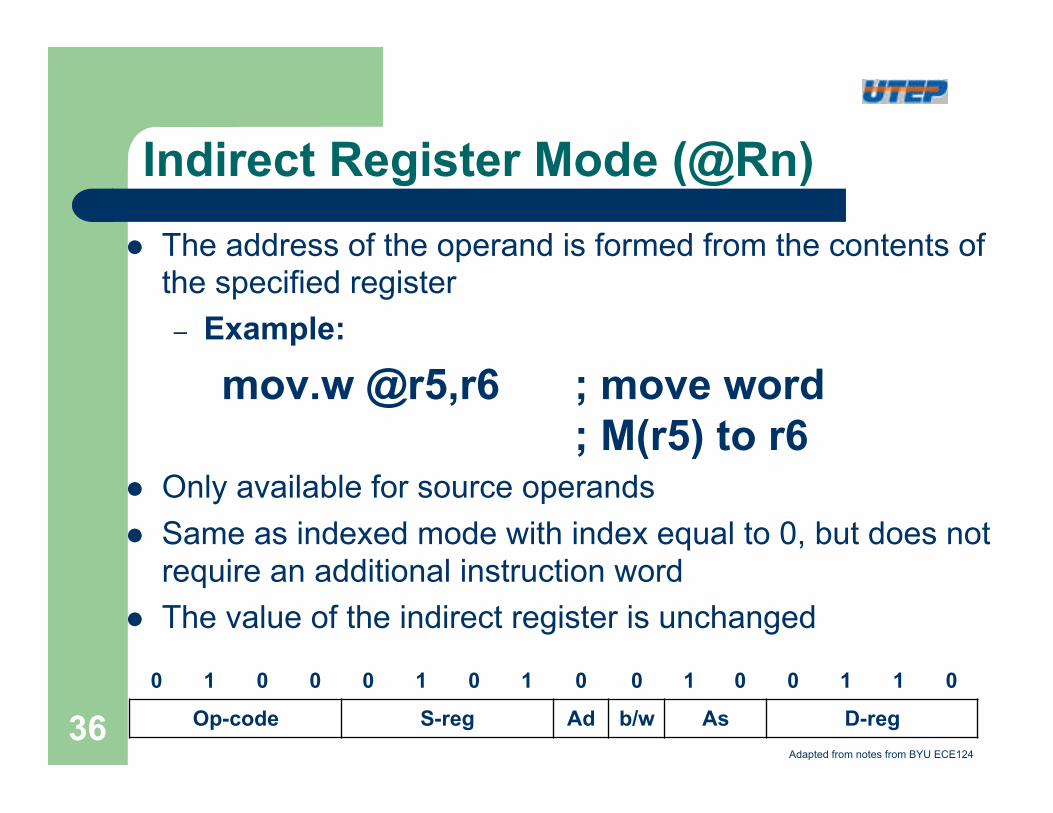
Indirect Register Mode (@Rn) l The address of the operand is formed from the contents of
the specified register – Example:
mov.w @r5,r6 ; move word ; M(r5) to r6
l Only available for source operands l Same as indexed mode with index equal to 0, but does not
require an additional instruction word l The value of the indirect register is unchanged
0 1 0 0 0 1 0 1 0 0 1 0 0 1 1 0
Op-code S-reg Ad b/w As D-reg Adapted from notes from BYU ECE124
36
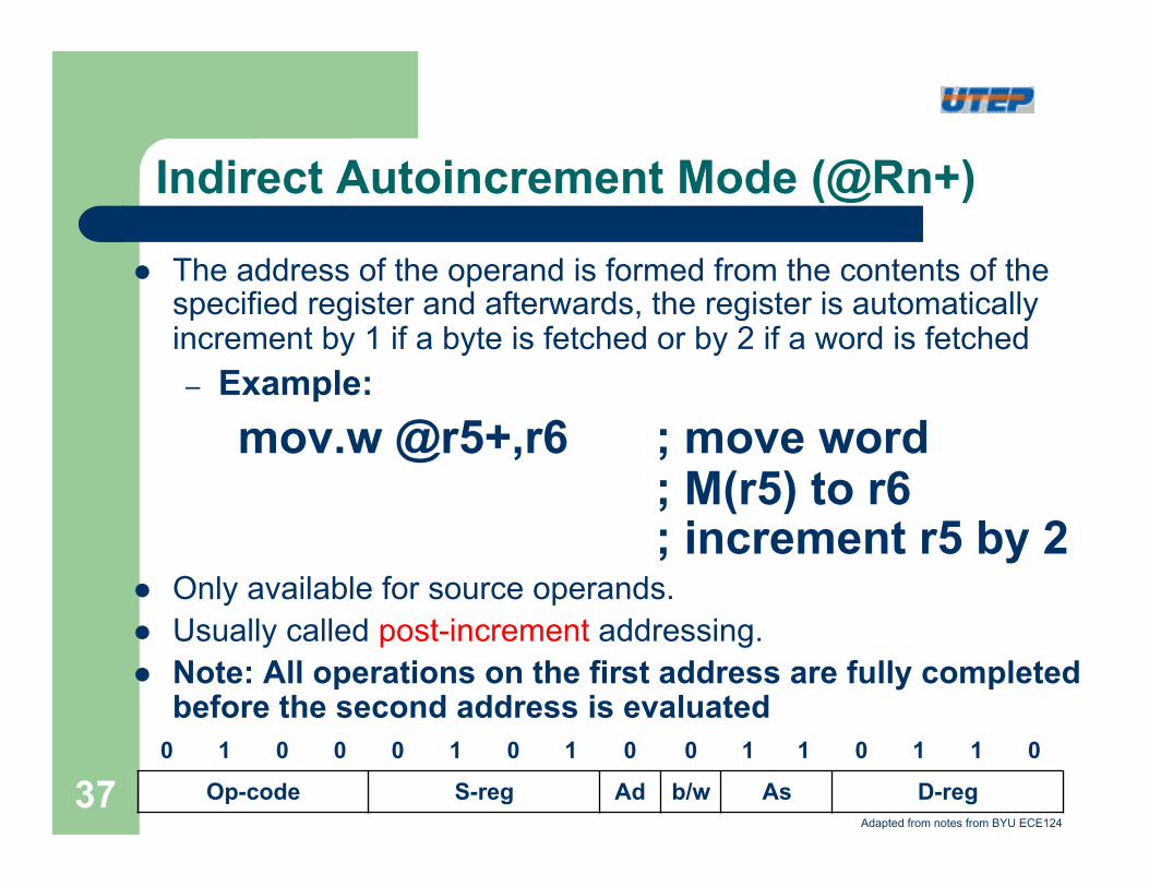
Indirect Autoincrement Mode (@Rn+)
l The address of the operand is formed from the contents of the specified register and afterwards, the register is automatically increment by 1 if a byte is fetched or by 2 if a word is fetched – Example:
mov.w @r5+,r6 ; move word ; M(r5) to r6 ; increment r5 by 2
l Only available for source operands. l Usually called post-increment addressing. l Note: All operations on the first address are fully completed
before the second address is evaluated 0 1 0 0 0 1 0 1 0 0 1 1 0 1 1 0
Op-code S-reg Ad b/w As D-reg Adapted from notes from BYU ECE124
37
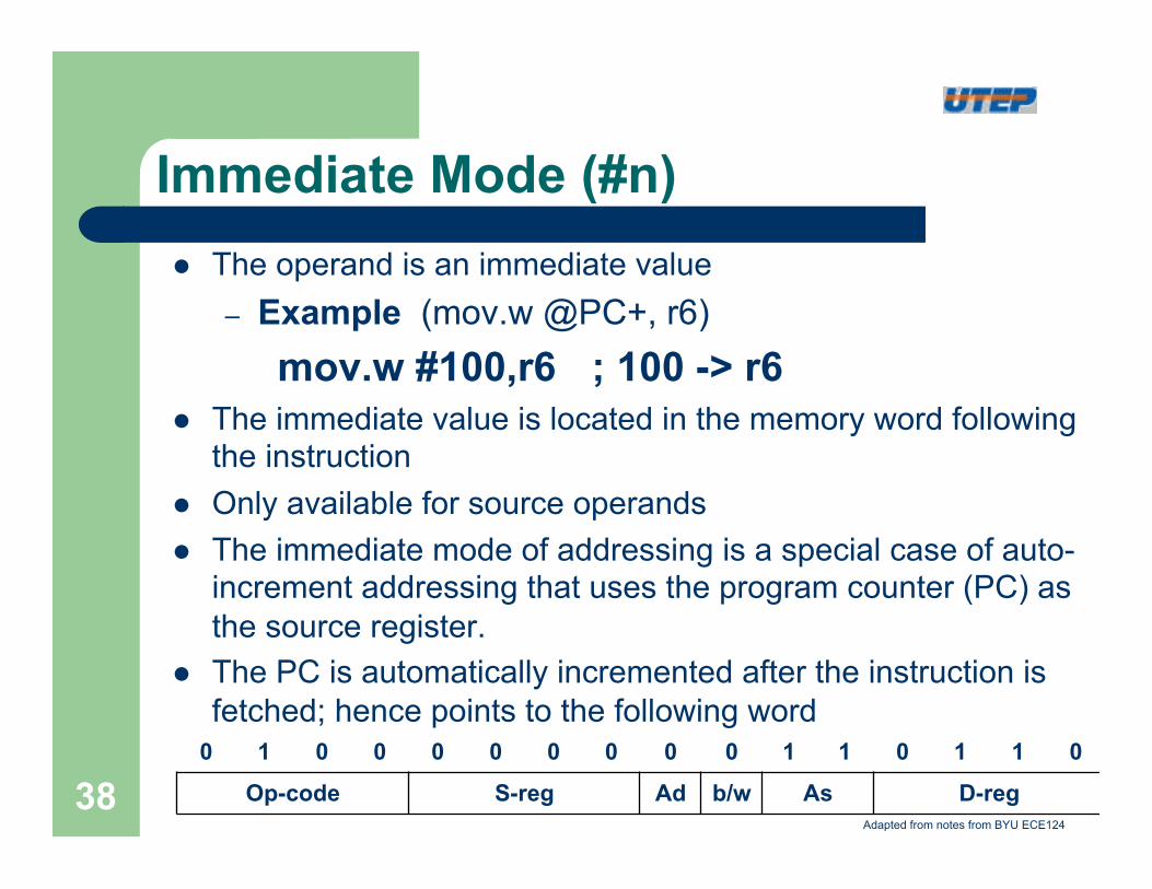
Immediate Mode (#n) l The operand is an immediate value
– Example (mov.w @PC+, r6) mov.w #100,r6 ; 100 -> r6
l The immediate value is located in the memory word following the instruction
l Only available for source operands l The immediate mode of addressing is a special case of auto-
increment addressing that uses the program counter (PC) as the source register.
l The PC is automatically incremented after the instruction is fetched; hence points to the following word
0 1 0 0 0 0 0 0 0 0 1 1 0 1 1 0
Op-code S-reg Ad b/w As D-reg Adapted from notes from BYU ECE124
38
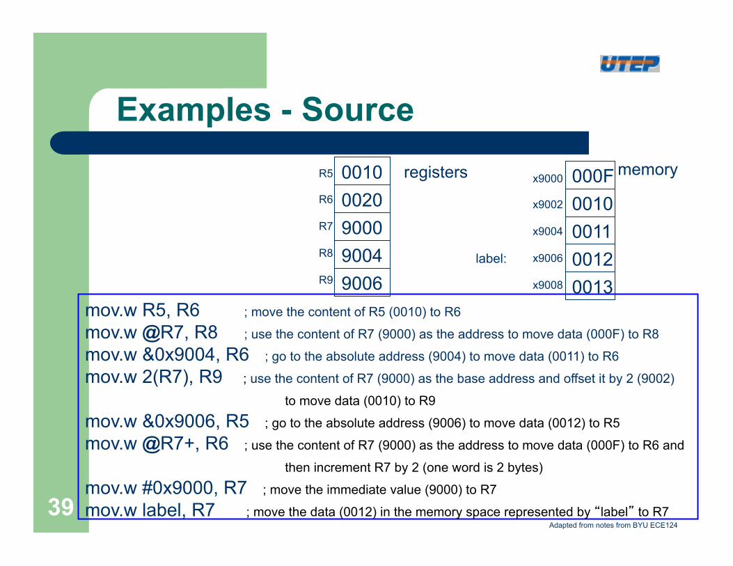
mov.w R5, R6 ; move the content of R5 (0010) to R6
mov.w @R7, R8 ; use the content of R7 (9000) as the address to move data (000F) to R8
mov.w &0x9004, R6 ; go to the absolute address (9004) to move data (0011) to R6
mov.w 2(R7), R9 ; use the content of R7 (9000) as the base address and offset it by 2 (9002)
to move data (0010) to R9 mov.w &0x9006, R5 ; go to the absolute address (9006) to move data (0012) to R5 mov.w @R7+, R6 ; use the content of R7 (9000) as the address to move data (000F) to R6 and
then increment R7 by 2 (one word is 2 bytes) mov.w #0x9000, R7 ; move the immediate value (9000) to R7
mov.w label, R7 ; move the data (0012) in the memory space represented by “label” to R7
Examples - Source
000F 0010 0011 0012 0013
x9000 x9002 x9004 x9006 x9008
0010 0020 9000 9004 9006
R5 R6 R7 R8 R9
registers memory
label:
Adapted from notes from BYU ECE124
39
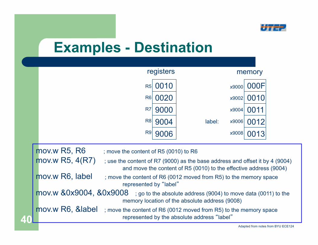
mov.w R5, R6 ; move the content of R5 (0010) to R6
mov.w R5, 4(R7) ; use the content of R7 (9000) as the base address and offset it by 4 (9004) and move the content of R5 (0010) to the effective address (9004)
mov.w R6, label ; move the content of R6 (0012 moved from R5) to the memory space represented by “label”
mov.w &0x9004, &0x9008 ; go to the absolute address (9004) to move data (0011) to the memory location of the absolute address (9008)
mov.w R6, &label ; move the content of R6 (0012 moved from R5) to the memory space represented by the absolute address “label”
Examples - Destination
000F 0010 0011 0012 0013
x9000 x9002 x9004 x9006 x9008
0010 0020 9000 9004 9006
R5 R6 R7 R8 R9
registers memory
label:
Adapted from notes from BYU ECE124 40
High Level vs. Assembly
l High Level Languages – More programmer friendly – More ISA independent – Each high-level statement translates to several
instructions in the ISA of the computer l Assembly Languages
– Lower level, closer to ISA – Very ISA-dependent – Each instruction specifies a single ISA instruction – Makes low level programming more user friendly – More efficient code
Adapted from notes from BYU ECE124
41
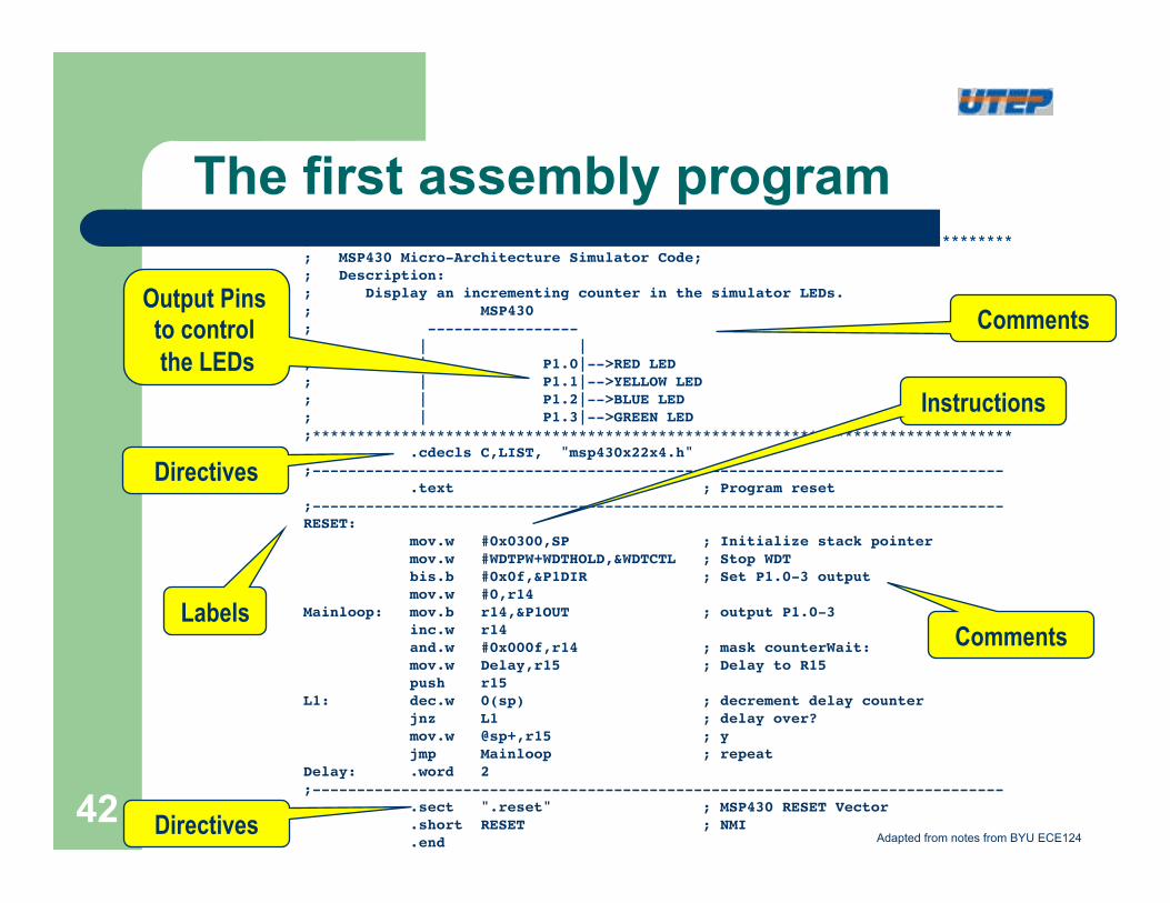
The first assembly program ;*******************************************************************************!; MSP430 Micro-Architecture Simulator Code;!; Description:!; Display an incrementing counter in the simulator LEDs.!; MSP430!; -----------------!; | |!; | P1.0|-->RED LED!; | P1.1|-->YELLOW LED!; | P1.2|-->BLUE LED!; | P1.3|-->GREEN LED!;*******************************************************************************
!.cdecls C,LIST, "msp430x22x4.h" !;------------------------------------------------------------------------------ !
!.text ; Program reset!;------------------------------------------------------------------------------!RESET: !
!mov.w #0x0300,SP ; Initialize stack pointer !!mov.w #WDTPW+WDTHOLD,&WDTCTL ; Stop WDT !!bis.b #0x0f,&P1DIR ; Set P1.0-3 output !!mov.w #0,r14!
Mainloop: mov.b r14,&P1OUT ; output P1.0-3 !!inc.w r14 !!and.w #0x000f,r14 ; mask counterWait: !!mov.w Delay,r15 ; Delay to R15 !!push r15!
L1: !dec.w 0(sp) ; decrement delay counter !!jnz L1 ; delay over? !!mov.w @sp+,r15 ; y !!jmp Mainloop ; repeat!
Delay: .word 2!;------------------------------------------------------------------------------!
!.sect ".reset" ; MSP430 RESET Vector !!.short RESET ; NMI !!.end
Labels
Directives
Directives
Instructions
Comments
Comments Output Pins to control the LEDs
Adapted from notes from BYU ECE124
42
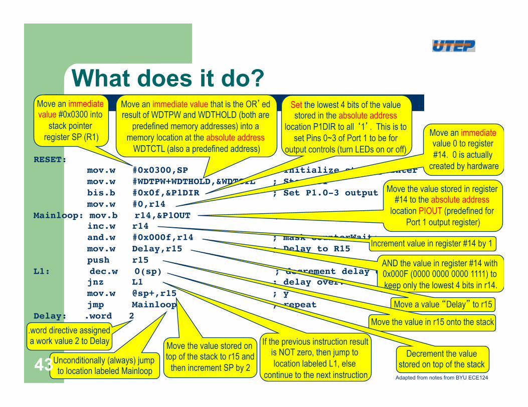
What does it do?
RESET: !! mov.w #0x0300,SP ; Initialize stack pointer !! mov.w #WDTPW+WDTHOLD,&WDTCTL ; Stop WDT !! bis.b #0x0f,&P1DIR ; Set P1.0-3 output !! mov.w #0,r14!
Mainloop: mov.b r14,&P1OUT ; output P1.0-3 !! inc.w r14 !! and.w #0x000f,r14 ; mask counterWait: !! mov.w Delay,r15 ; Delay to R15 !! push r15!
L1: dec.w 0(sp) ; decrement delay counter !! jnz L1 ; delay over? !! mov.w @sp+,r15 ; y !! jmp Mainloop ; repeat!
Delay: .word 2!
Move an immediate value #0x0300 into
stack pointer register SP (R1)
Move an immediate value that is the OR’ed result of WDTPW and WDTHOLD (both are
predefined memory addresses) into a memory location at the absolute address
WDTCTL (also a predefined address)
Set the lowest 4 bits of the value stored in the absolute address
location P1DIR to all ‘1’. This is to set Pins 0~3 of Port 1 to be for
output controls (turn LEDs on or off)
Move an immediate value 0 to register #14. 0 is actually
created by hardware
Move the value stored in register #14 to the absolute address
location PIOUT (predefined for Port 1 output register)
Increment value in register #14 by 1
AND the value in register #14 with 0x000F (0000 0000 0000 1111) to keep only the lowest 4 bits in r14.
Move a value “Delay” to r15
Move the value in r15 onto the stack
Decrement the value stored on top of the stack
If the previous instruction result is NOT zero, then jump to location labeled L1, else
continue to the next instruction
Move the value stored on top of the stack to r15 and
then increment SP by 2 Unconditionally (always) jump to location labeled Mainloop
.word directive assigned a work value 2 to Delay
Adapted from notes from BYU ECE124
43
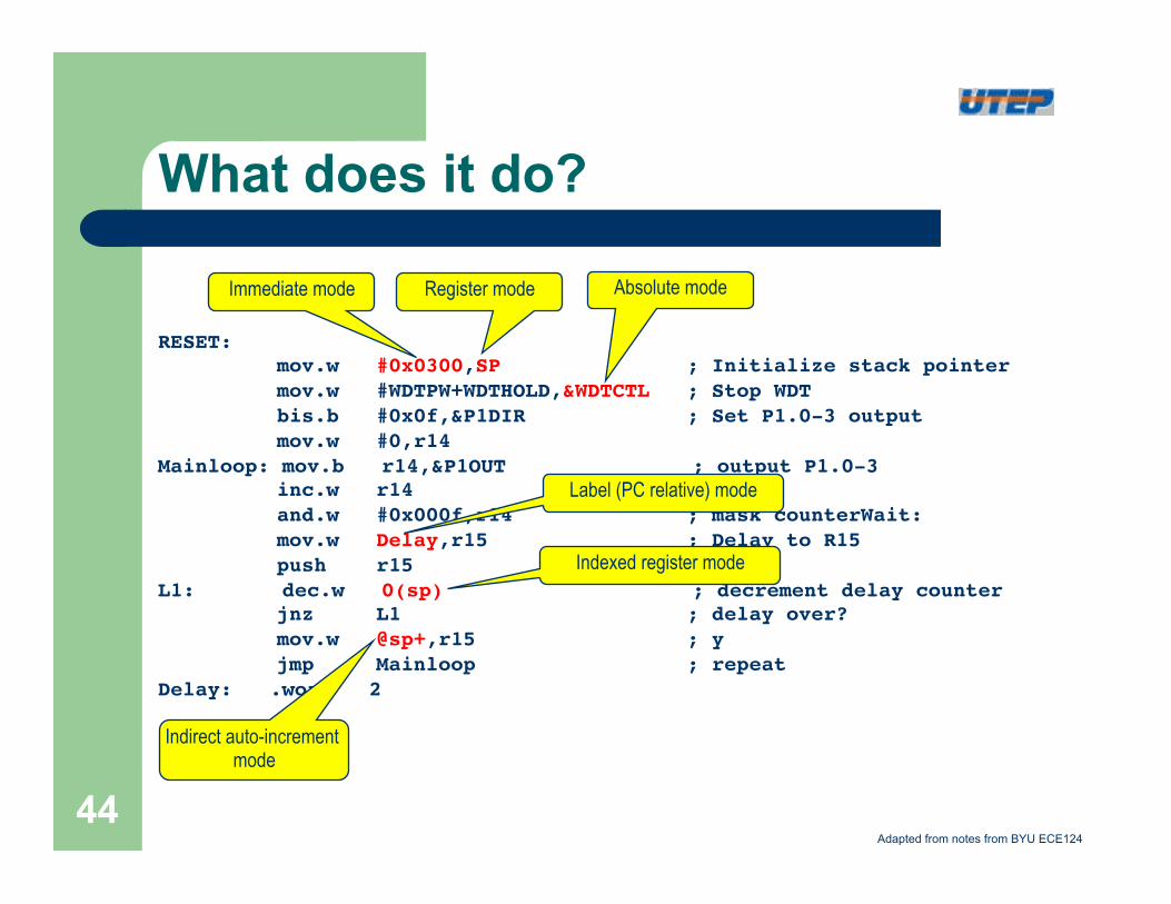
RESET: !! mov.w #0x0300,SP ; Initialize stack pointer !! mov.w #WDTPW+WDTHOLD,&WDTCTL ; Stop WDT !! bis.b #0x0f,&P1DIR ; Set P1.0-3 output !! mov.w #0,r14!
Mainloop: mov.b r14,&P1OUT ; output P1.0-3 !! inc.w r14 !! and.w #0x000f,r14 ; mask counterWait: !! mov.w Delay,r15 ; Delay to R15 !! push r15!
L1: dec.w 0(sp) ; decrement delay counter !! jnz L1 ; delay over? !! mov.w @sp+,r15 ; y !! jmp Mainloop ; repeat!
Delay: .word 2!
Immediate mode Register mode Absolute mode
Label (PC relative) mode
Indexed register mode
Indirect auto-increment mode
Adapted from notes from BYU ECE124
What does it do?
44
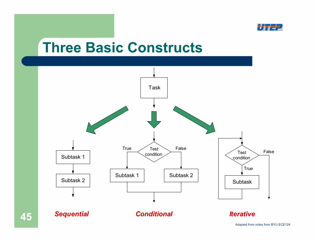
Three Basic Constructs
Task
Subtask 1
Subtask 2Subtask 1 Subtask 2
Testcondition
Subtask
Testcondition
Sequential Conditional Iterative
True
True
FalseFalse
Adapted from notes from BYU ECE124
45
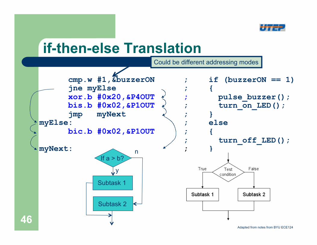
if-then-else Translation
if (buzzerON == 1) { pulse_buzzer(); turn_on_LED(); } else { turn_off_LED(); }
cmp.w #1,&buzzerON ; jne myElse ; xor.b #0x20,&P4OUT ; bis.b #0x02,&P1OUT ; jmp myNext ; myElse: ; bic.b #0x02,&P1OUT ; ; myNext: ;
Could be different addressing modes
If a > b?
Subtask 1
Subtask 2
n
y
Adapted from notes from BYU ECE124
46
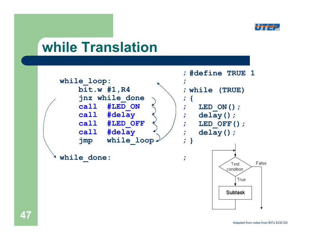
while Translation #define TRUE 1 while (TRUE) { LED_ON(); delay(); LED_OFF(); delay(); }
; while_loop: ; bit.w #1,R4 ; jnz while_done ; call #LED_ON ; call #delay ; call #LED_OFF ; call #delay ; jmp while_loop ; while_done: ;
Adapted from notes from BYU ECE124
47
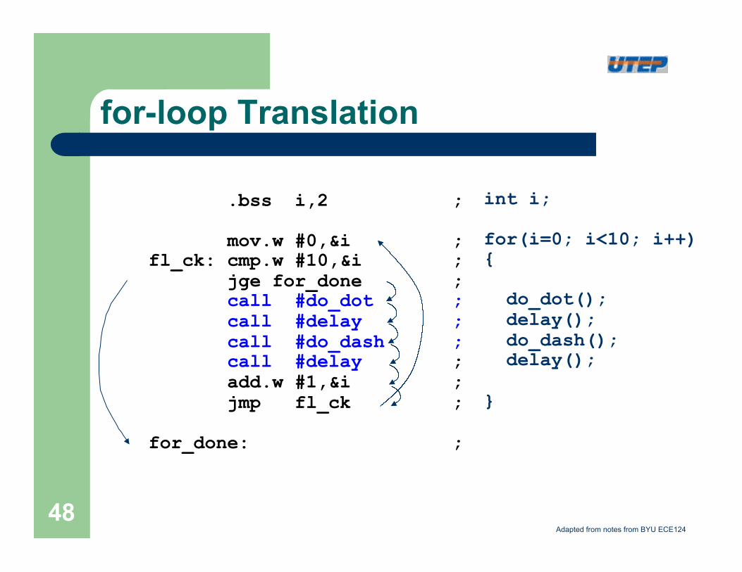
for-loop Translation
int i; for(i=0; i<10; i++) { do_dot(); delay(); do_dash(); delay(); }
.bss i,2 ; mov.w #0,&i ; fl_ck: cmp.w #10,&i ; jge for_done ; call #do_dot ; call #delay ; call #do_dash ; call #delay ; add.w #1,&i ; jmp fl_ck ; for_done: ;
Adapted from notes from BYU ECE124 48
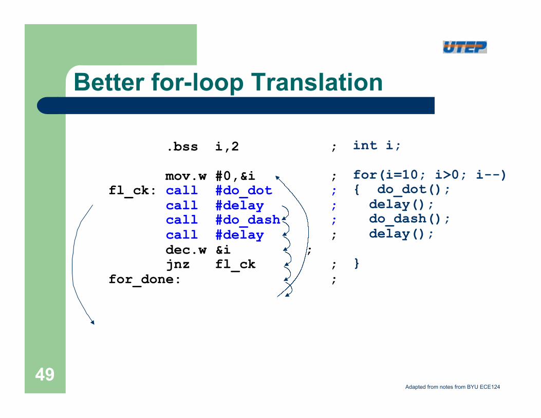
Better for-loop Translation
int i; for(i=10; i>0; i--) { do_dot(); delay(); do_dash(); delay(); }
.bss i,2 ; mov.w #0,&i ; fl_ck: call #do_dot ; call #delay ; call #do_dash ; call #delay ; dec.w &i ; jnz fl_ck ; for_done: ;
Adapted from notes from BYU ECE124 49
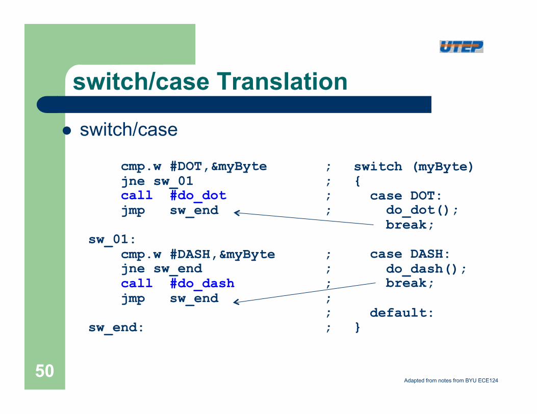
switch/case Translation
l switch/case
switch (myByte) { case DOT: do_dot(); break; case DASH: do_dash(); break; default: }
cmp.w #DOT,&myByte ; jne sw_01 ; call #do_dot ; jmp sw_end ; sw_01: cmp.w #DASH,&myByte ; jne sw_end ; call #do_dash ; jmp sw_end ; ; sw_end: ;
Adapted from notes from BYU ECE124 50
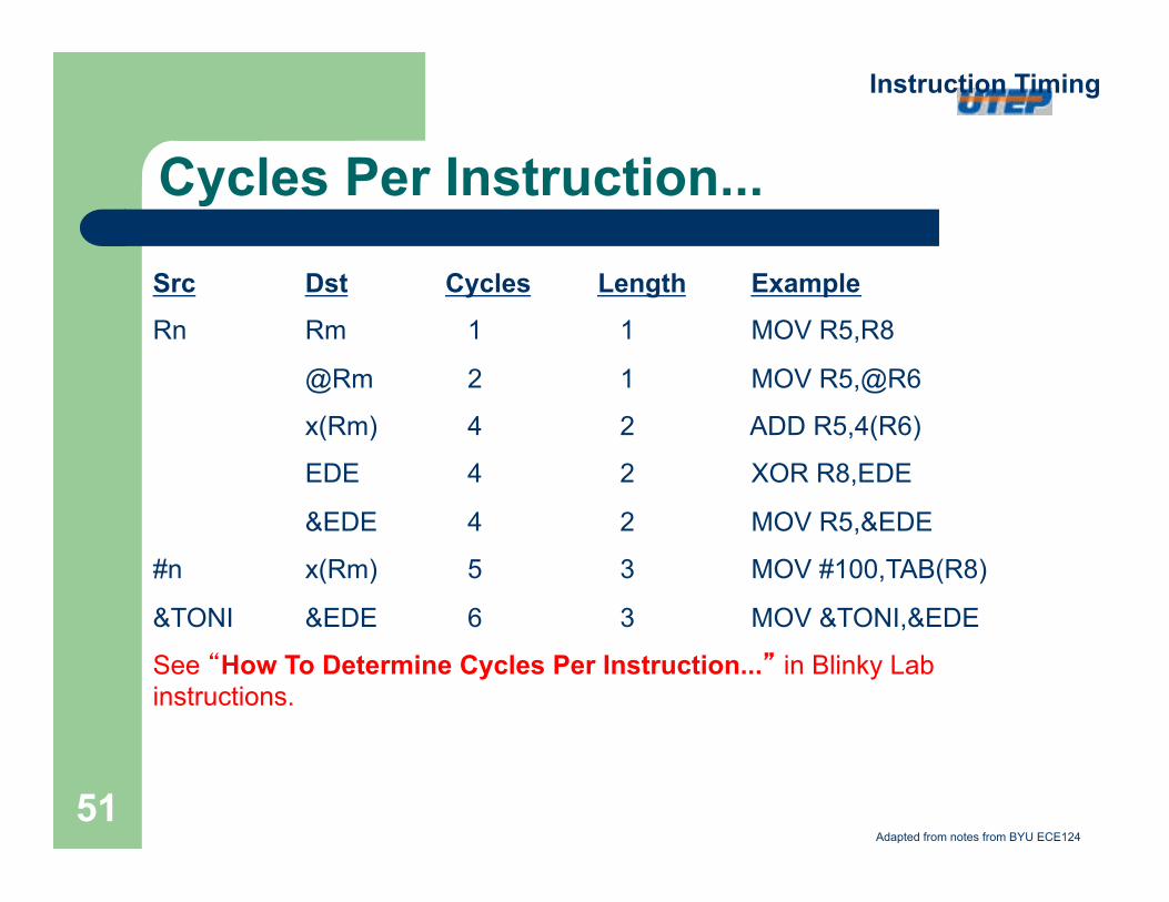
Cycles Per Instruction...
Src Dst Cycles Length Example
Rn Rm 1 1 MOV R5,R8
@Rm 2 1 MOV R5,@R6
x(Rm) 4 2 ADD R5,4(R6)
EDE 4 2 XOR R8,EDE
&EDE 4 2 MOV R5,&EDE
#n x(Rm) 5 3 MOV #100,TAB(R8)
&TONI &EDE 6 3 MOV &TONI,&EDE
See “How To Determine Cycles Per Instruction...” in Blinky Lab instructions.
Instruction Timing
Adapted from notes from BYU ECE124
51
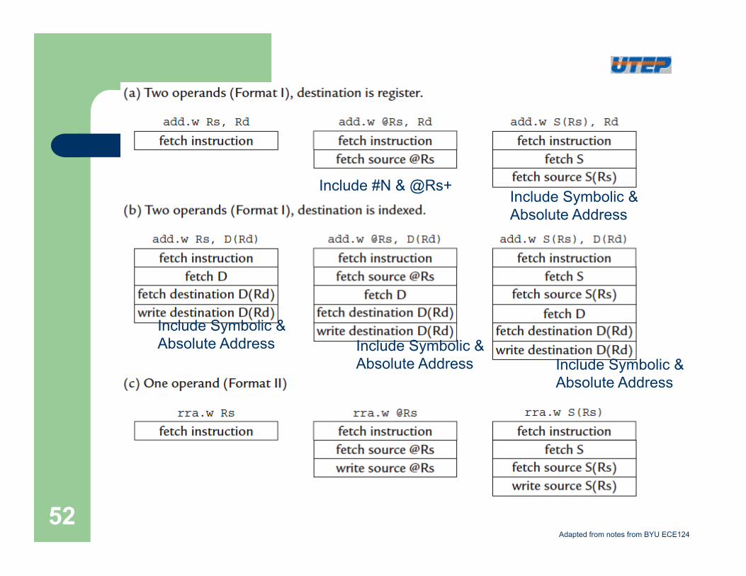
Include #N & @Rs+ Include Symbolic & Absolute Address
Include Symbolic & Absolute Address Include Symbolic &
Absolute Address Include Symbolic & Absolute Address
Adapted from notes from BYU ECE124
52
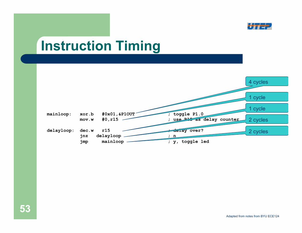
Instruction Timing
mainloop: xor.b #0x01,&P1OUT ; toggle P1.0 mov.w #0,r15 ; use R15 as delay counter delayloop: dec.w r15 ; delay over? jnz delayloop ; n jmp mainloop ; y, toggle led
4 cycles
1 cycle
1 cycle
2 cycles
2 cycles
Adapted from notes from BYU ECE124
53