Assembly Instructions EMD F-3 DUAL ROAD DIESEL
10
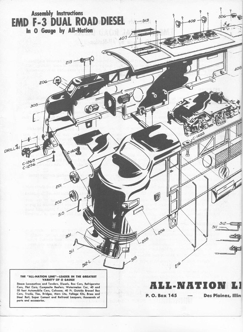
Assembly Instructions EMD F-3 DUAL ROAD DIESEL In 0 Gauge by All-Nation Before starting construction of your F-3 unit, examine all castings and remove all flash. Be careful not to file tongues off top of side casting and groove on bottom of roof casting. All detail parts should be added before unit is assembled. A: preliminary assembly is recommend- ed to check the fit to the parts, end to sides, sides to roof, etc. DETAILING To the end (404)fit two grab. irons (these are formed from. 032wire), then mount coupler using 2-56 screw. Then install wire forms for uncoupling (see detail drawing and instructions). " Cement fiber diaphram (508)to striker plate (509). Whendry cement assembly to the door frame with striker plate away from end. Permit the floor sill to come through inside of striker plate when diaphram is compressed. Fit door windowglass into frame from the inside. (donot install till painting is finished. Nowtake the sides (304-305). Youhave a choice of either one or two headlites. If you want only one, file out the membrane in nose door. NOTE: if you want to use a MARSlite both lites will have to be used, the top one for the MARSand the bottom for the headlite. If you want 45 0 number boards see drawing and instructions for their installation. Fit hand rails (formed from wire in kit) in nose and sides. Then mount front coupler using 2-56screw. Nowmount the uncoupling wire forms on the nose as shown on the drawing. (For best results in Operating Automatic Couplers, solder drawbar handle wire form closed after it has been assembled and installed). Fit all windowsat this time. These are fitted from the back of the casting and not from the front as shown on the drawings. (Donot install till painting is finished). Place horns in place, one facing forward and one back, andcement or swedgeon the inside. Acetate grill can nowbe cut to fit. This shouldnotbemounteduntil after theunitis painted. The roof is nowdrilled if you want to put the train heating stacks on the rear of the unit. Mark off the roof as shown on drawing and drill with a 17/64" drill. Place the stacks in place and glue or swedge in place. Mountexhaust stacks in place. Mountroof lift rings and bend over on the inside. Fit plasti~ grill in opening in roof. (Donot install till painting is finished). ASSEMBLING Assemble end and one side with 4-40 screws (C-1405). Do not draw up tight. Start the turnbuckles (222)into bosses in side. Set headlite lenses in place, flat side facing outside. Then start turnbuckles in other side. Draw sides together, using 1/4" open end wrench being careful not to deform the castings. The tongues and grooves must line up. If sides are bent out of shape, loosen and bend back into shape. Nowfasten other side to end with 4-40 screws. Fasten roof to sides and ends with 4-40 screws. Again be careful that tongues and grooves line up. Bodycan nowbe painted to suit. When paint is dry, mount windowsand roof grill using Walthers Gooor a goodclear cement. Mountthe acetate grill. If instructions are followed grills will not come loose. Lite assembly can nowbe placed in lite compartment andheldinplace withspring wire ring. B unit is assembled the same as the A, but use two ends. The roof is attached in the same manner as the A.
Transcript of Assembly Instructions EMD F-3 DUAL ROAD DIESEL
Assembly InstructionsEMD F-3 DUAL ROAD DIESEL
In 0 Gauge by All-Nation
Before starting construction of your F-3 unit, examine all castings and remove all flash.Be careful not to file tongues off top of side casting and groove on bottom of roof casting. Alldetail parts should be added before unit is assembled. A: preliminary assembly is recommend-ed to check the fit to the parts, end to sides, sides to roof, etc.
DETAILING
To the end (404)fit two grab. irons (these are formed from. 032wire), then mount couplerusing 2-56 screw. Then install wire forms for uncoupling (see detail drawing and instructions).
"Cement fiber diaphram (508)to striker plate (509). Whendry cement assembly to the doorframe with striker plate away from end. Permit the floor sill to come through inside of strikerplate when diaphram is compressed.
Fit door windowglass into frame from the inside. (donot install till painting is finished.Nowtake the sides (304-305). Youhave a choice of either one or two headlites. If you
want only one, file out the membrane in nose door. NOTE: if you want to use a MARSlite bothlites will have to be used, the top one for the MARSand the bottom for the headlite. If you want450 number boards see drawing and instructions for their installation.
Fit hand rails (formed from wire in kit) in nose and sides. Then mount front coupler using2- 56 screw. Nowmount the uncoupling wire forms on the nose as shown on the drawing. (Forbest results in Operating Automatic Couplers, solder drawbar handle wire form closed after ithas been assembled and installed).
Fit all windowsat this time. These are fitted from the back of the casting and not fromthe front as shown on the drawings. (Donot install till painting is finished).
Place horns in place, one facing forward and one back, andcement or swedgeon the inside.Acetate grill can nowbe cut to fit. This shouldnotbemounteduntil after the unit is painted.The roof is nowdrilled if you want to put the train heating stacks on the rear of the unit.
Mark off the roof as shown on drawing and drill with a 17/64" drill. Place the stacks in placeand glue or swedge in place. Mount exhaust stacks in place. Mount roof liftrings and bendover on the inside. Fit plasti~ grill in opening in roof. (Donot install till painting is finished).
ASSEMBLINGAssemble end and one side with 4-40 screws (C-1405). Do not draw up tight. Start the
turnbuckles (222)into bosses in side. Set headlite lenses in place, flat side facing outside.Then start turnbuckles in other side. Draw sides together, using 1/4" open end wrench beingcareful not to deform the castings. The tongues and grooves must line up. If sides are bentout of shape, loosen and bend back into shape.
Nowfasten other side to end with 4-40 screws.Fasten roof to sides and ends with 4-40 screws. Again be careful that tongues and grooves
line up.Body can nowbe painted to suit. When paint is dry, mount windows and roof grill using
Walthers Gooor a good clear cement. Mount the acetate grill. If instructions are followedgrills will not come loose.
Lite assembly can nowbe placed in lite compartment andheld inplace withspring wire ring.B unit is assembled the same as the A, but use two ends. The roof is attached in the same
manner as the A.
Asselllbly InstructionsEMD F·3 DUAL ROAD DIESEL
In 0 Gauge by All-Nation_513
~,
THE "ALL-NATION LINE"-LEADER IN THE GREATESTVARIETYOF 0 GAUGE
Steam locomotives and Tenders, Di"sels, Box Cars, RefrigeratorCars, Flat Cars, Composite Reefers, Watermelon Car .w andSO foot Automobile Cars, Caboose, .w Ft. Outside Br~ced BoxCars, Trucks, Ties, Bridges, Mars Lite, Foliage Kits, Brau andSteel Rail, Super Cement and 'Railroad lacquers, thousands ofparts and a~ceuaries. '
P. O. Box 145 Des Plaines, lIIin
i-,
A
E560017
LOCATION OF 4S· NUMBERBOARDS ON THE
EMD F·3 DUll ROID DIESEL
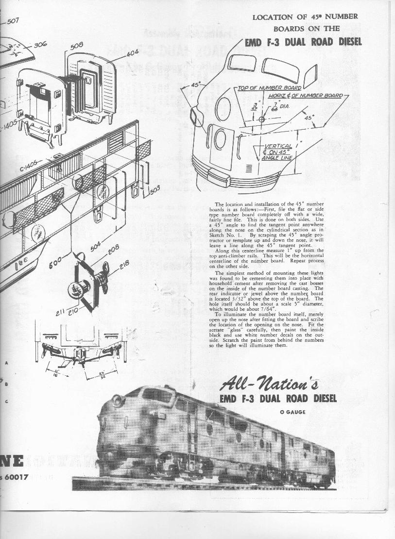
The location and installation of the 450 numberboards is as follows :-First, file the flat or sidetype number board completely off with a wide,fairly fine file. This is done on both sides. Usea 450 angle to find the tangent point anywherealong the nose on the cylindrical section as inSketch No. 1. By scraping the 450 angle pro-tractor or template up and down the nose, it willleave a line along the 450 tangent point.
Along this centerline measure 1" up from thetop anti-climber rails. This will be the horizontalcenterline of the number board. Repeat processon the other side.
The simplest method of mounting these lightswas found.ro be cementing them into place withhousehold" cement after removing the cast bosseson the inside of the number board casting. Therear indicator or jewel above the number boardis located 3/32" above the top of the board. Thehole itself should be about a scale 5" diameter,which would be about 7/64".
To illuminate the number board itself, merelyopen up the nose after fitting the board and scribethe location of the opening on the nose. Fit theacetate "glass" carefully, then paint the insideblack and use white number decals on the out-side. Scratch the paint from behind the numbersso the light will illuminate them.
/lU-~4-F·3 DUll ROAD DIESR
o GAUGE
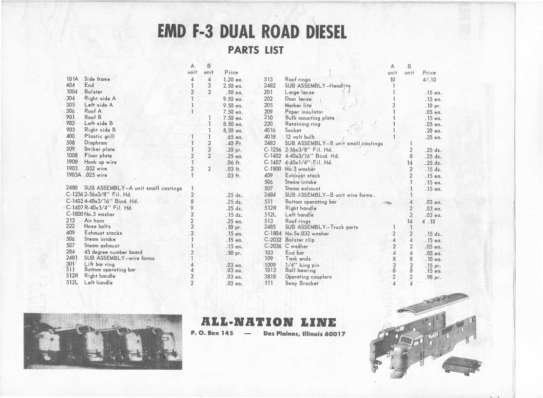
EMD F-3 DUAL ROAD DIESELPARTS LIST
A B A Bunit unit Price 1 unit unit Price
lOlA Side frame 4 4 1.20 ea. 513 Roof rings 10 4/.10404 End 1 2 2.50 ea. 2482 SUB ASSEMBLY -Headyt7 1lD04 Bolster 2 2 .50 ea. 201 Large lense 1 .15 ea.304 Right side A 1 9.50 ea. 202 Door lense J ). 1 .15 ea.305 Left side A 1 9.50 ea. 205 Marker lite . ~ 2 .10 pro306 Roof A 209 Paper insulator
v1 .05 ea.1 7.50 ea.
901 Roof B 1 7.50 eo, 210 Bulb mounting plate 1 .15 ea.902 Left side B 1 8.50 ea. 220 Retaining ring ........\
, 1 .05 ea./ '
903 Right side B 1 8,50 ea. 4016 Socket ~ ~ 1 .20 ea.-400 Plastic grill 1 1 .65 ea. 4018 12 volt bulb I 1 .25 ea.508 Diaphram 1 2 .40 Pro 2483 SUB ASSEMBLY-B unit small/castings 1509 Striker plate 1 2 .20 pro C-1256 2-56x3/8" Fi I. Hd. 2 .25 dz.1008 Floor plate 2 2 .25 ea. C-1402 4-40x3/16" Bind. Hd. 8 .25 dz.1908 Hook up wire 1 .06 ft. C-1407 A_cfOx1/4"'fil. Hd. 14 .25 dz.1903 .032 wire 2 2 .03 ft. C-1800 N0'1 washer 2 .15 dz.1903A .025 wire 1 .03 ft. 409 Exh,aust stack 2 .15 ea.
506 Steam intake 1 .15 ea.2480 SUB ASSEMBLY -A unit small castings 1 507 Steam exhaust 1 .15 ea.C-12562-56x3/8" Fi I. Hd. 2 .25 dz. 2484 SUB ASSEMBLY -B unit wire forms. 1C-14024-40x3/16" Bind. Hd. 8 .25 dz. 511 Bottom operating bar ~ 4 .03 ea.C-1407R-40x1l4" Fil. Hd. 9 .25 dz. .512R Right handle 2 .03 ea.C-1800 No.3 washer 2. .15 dz.. 512L Left handle 2 .03 ea.213 Air horn 2 .25 ea. 513 Roof rings 14 4 .10222 Nose bolts 2 .50 pro 2485 SUB ASSEMBLY - Truck parts 1 1409 Exhaust stacks 2. .15 ea. C-1804 No.5x.032 washer 2 '2 .15 dz.506 Steam intake 1 .15 ea, C-2032 Bolster clip 4 4 .15 ea.507 Steam exhaust 1 .15 ea. C-2036 .C washer 2 2 .05 ea.204 45 degree number board 2 .50 pr, 103 End bar 4 4 .05 ea.248] SUB ASSEMBLY-wire forms 1 109 Tank ends 8 8 .lD ea.30-1 Lift bar ring 4 .03 ea. 1009 1/4" king pin 2 2 .15 pro.511 Bottom operating bar 4 .03 ea. 1013 Ball bearing 8 8 .15 ea.512R Right handle 2 .03 ea. 3818 Operating couplers 2 2 .98 pro512L Left handle 2 .03 ea. III Sway Bracket 4 4
A.... ·NATION I.INEP. O. Box 145 Des Plaines, Illinois 6001 7
F-3 - F·7 - GP-7 -In 0 Gauge by All-Nation
TRUCKS
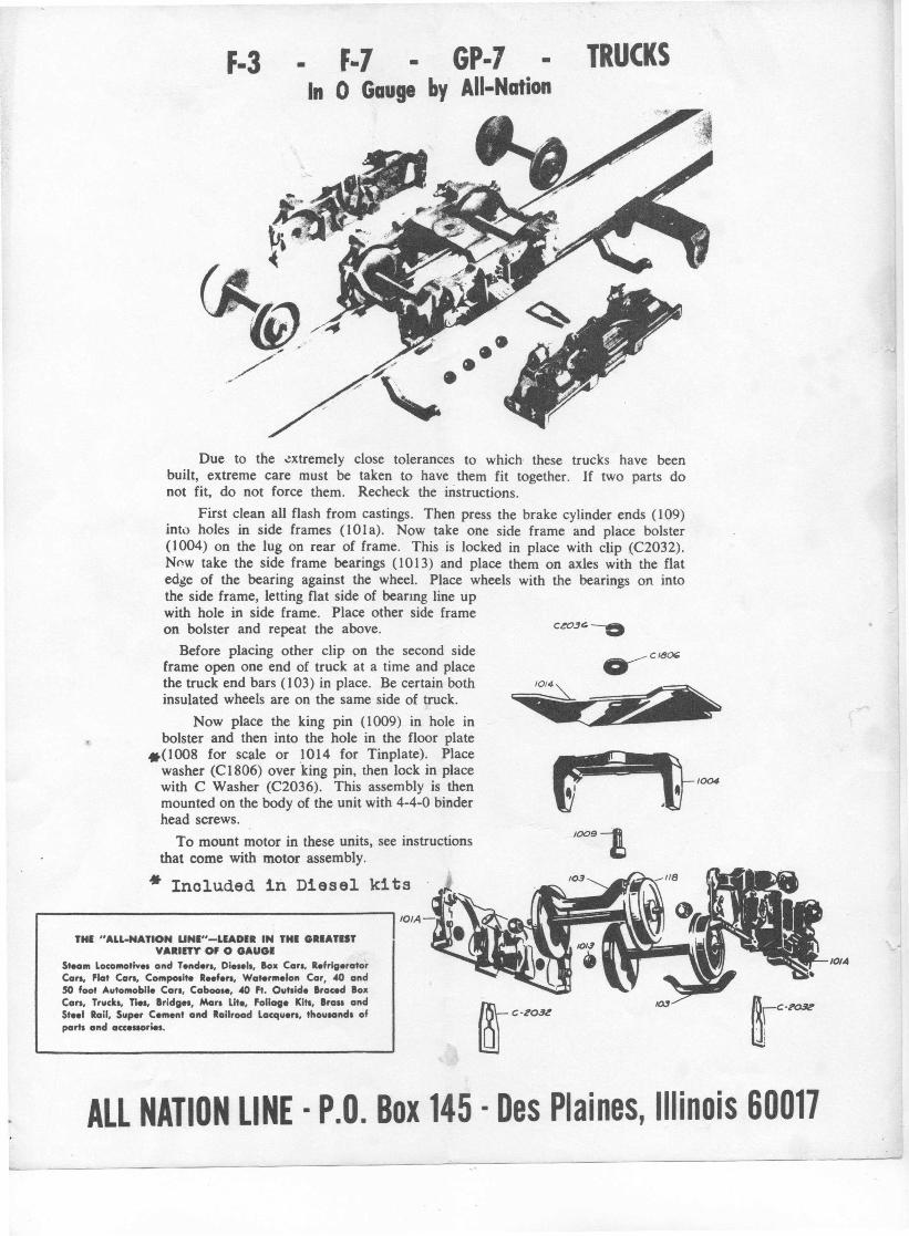
Due to the extremely close tolerances to which these trucks have beenbuilt, extreme care must be taken to have them fit together. If two parts donot fit, do not force them. Recheck the instructions.
First clean all flash from castings. Then press the brake cylinder ends (109)into holes in side frames (IOta). Now take one side frame and place bolster(1004) on the lug on rear of frame. This is locked in place with clip (C2032).Now take the side frame bearings (1013) and place them on axles with the flatedge of the bearing against the wheel. Place wheels with the bearings on intothe side frame, letting flat side of beanng line upwith hole in side frame. Place other side frameon bolster and repeat the above. C~03~----O
Before placing other clip on the second sideframe open one end of truck at a time and placethe truck end bars (103) in place. Be certain bothinsulated wheels are on the same side of truck.
Now place the king pin (1009) in hole inbolster and then into the hole in the floor plate
.(1008 for scale or 1014 for Tinplate). Placewasher (CI806) over king pin, then lock in placewith C Washer (C2036). This assembly is thenmounted on the body of the unit with 4-4-0 binderhead screws.
To mount motor in these units, see instructionsthat come with motor assembly.
* Inoluded in Diesel kits
1004
IOO9~
lOlA
10114
THI "ALL.NATION UNI"-LIADIR IN THI GRIATISTVARIETY'OF 0 GAUGI
St.om locomotiv•• and T.nd .... Di••• I•• Bo" Co... R.frlgerotorCo... Flat Co... Compo.it. R•• f.... Watermelon Car. 40 and50 foot Automobile Co... Coboo.e. 40 ft. Outside Brac.d BoltCan. Truck•• Tie•• Bridge•• Man lite, foliage Kill, BrOil andSt.. 1 Roil, Super C.ment and Railroad locqu ... , thoulOnd. ofport. and occ.uoriel.
ALL NATION LINE · P.O. Box 145 · Des Plaines, Illinois 60017
TaE AI.I.·NATION1-31-7---------------·POWERUNIT
I.INE • • •
THis weight fUFnishedwith Auxiliary Unit
~.. _~lI\NST'RUCTIO~S,
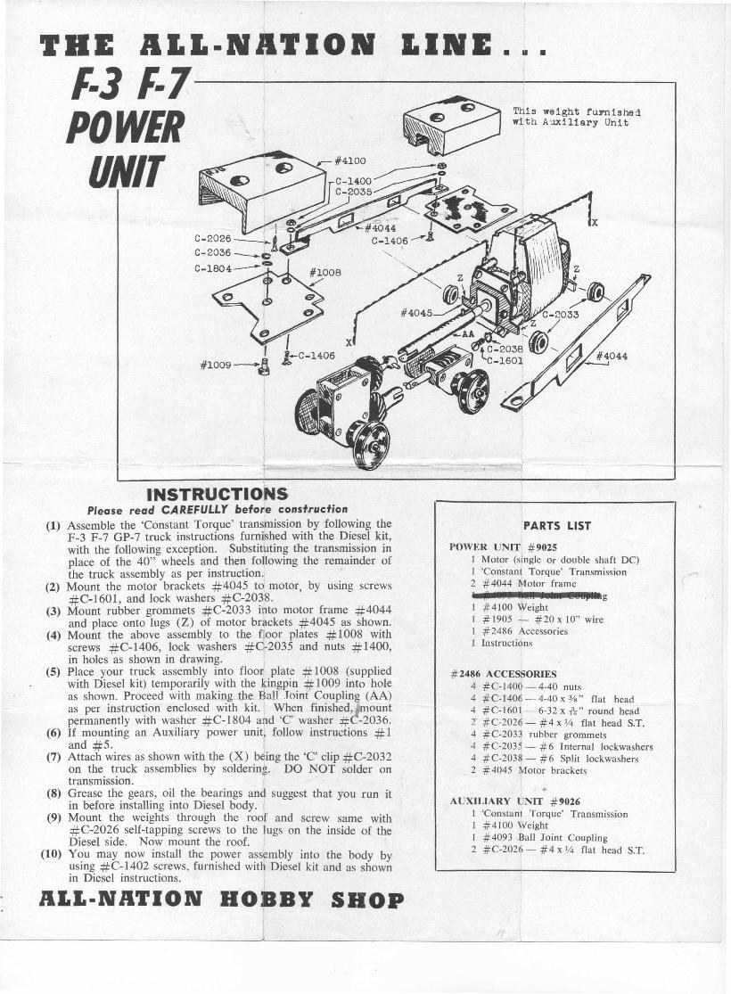
Please read CAREFULLY before construction(1) Assemble the 'Constant Torque' transmission by following the
F-3 F-7 GP-7 truck instructions furnished with the Diesel kit,with the following exception. Substituting the transmission inplace of the 40" wheels and then following the remainder ofthe truck assembly as per instruction.
(2) Mount the motor brackets #4045 to motor, by using screws#C-1601, and lock washers #C-2038.
(3) Mount rubber grommets #C-2033 into motor frame #4044and place onto lugs (Z) of motor brackets #4045 as shown.
(4) Mount the above assembly to the floor plates # 1008 withscrews #C-1406, lock washers #C-2035 and nuts #1400,in holes as shown in drawing.
(5) Place your truck assembly into floor plate # 1008 (suppliedwith Diesel kit) temporarily with the kingpin # 1009 into holeas shown. Proceed with makingthe, Ball Joint Coupling (AA)as per instruction enclosed with kit. When finished, mountpermanently with washer #C-1804 and 'C' washer # -2036.
(6) If mounting an Auxiliary power unit? follow instructions # 1and #5. ,
(7) Attach wires as shown with the (X) being the 'C' clip #C-2032on the truck assemblies by soldering. DO NOT solder ontransmission.
(8) Grease the gears, oil the bearings and suggest that you run itin before installing into Diesel body.
(9) Mount the weights through the roof and screw same with#C-2026 self-tapping screws to the lugs on the inside of theDiesel side. Now mount the roof.
(10) You may now install the power assembly into the body byusing #C-1402 screws, furnished with Diesel kit and as shownin Diesel instructions.
PARTS LIST
POWER UNIT' #90251 Motor (single Or double shaft DC)1 'Constant Torque' Transmission2 # 4044 ~,fotor frame
g1 #4100 Weight1 # 1905 - #20 x 10" wire1 #2486 Accessories1 Instructions
# 2486 ACCESSORIES4 # C-1400 - 4-40 nuts4 #C-1406 - 4-40 x %" flat head4 #C-1601- 6-32 x 11;" round head2' #C-202~ - #4 x l,-{j flat head S.T.4 #C-2033 rubber grommets4 #C-2035 - #6 Internal lockwashers4 #C-2038 - #6 Split lockwashers2 #4045 Motor brackets
.. .AUXILIARY UNIT #'026
1 'Constant Torque' Transmission1 #4100 Weight1 #4093 Ball Joint Coupling2 #C-2026 - #4 x l,-{j flat head S.T.
A.... ·NATION BOBBY SHOP/
If9027
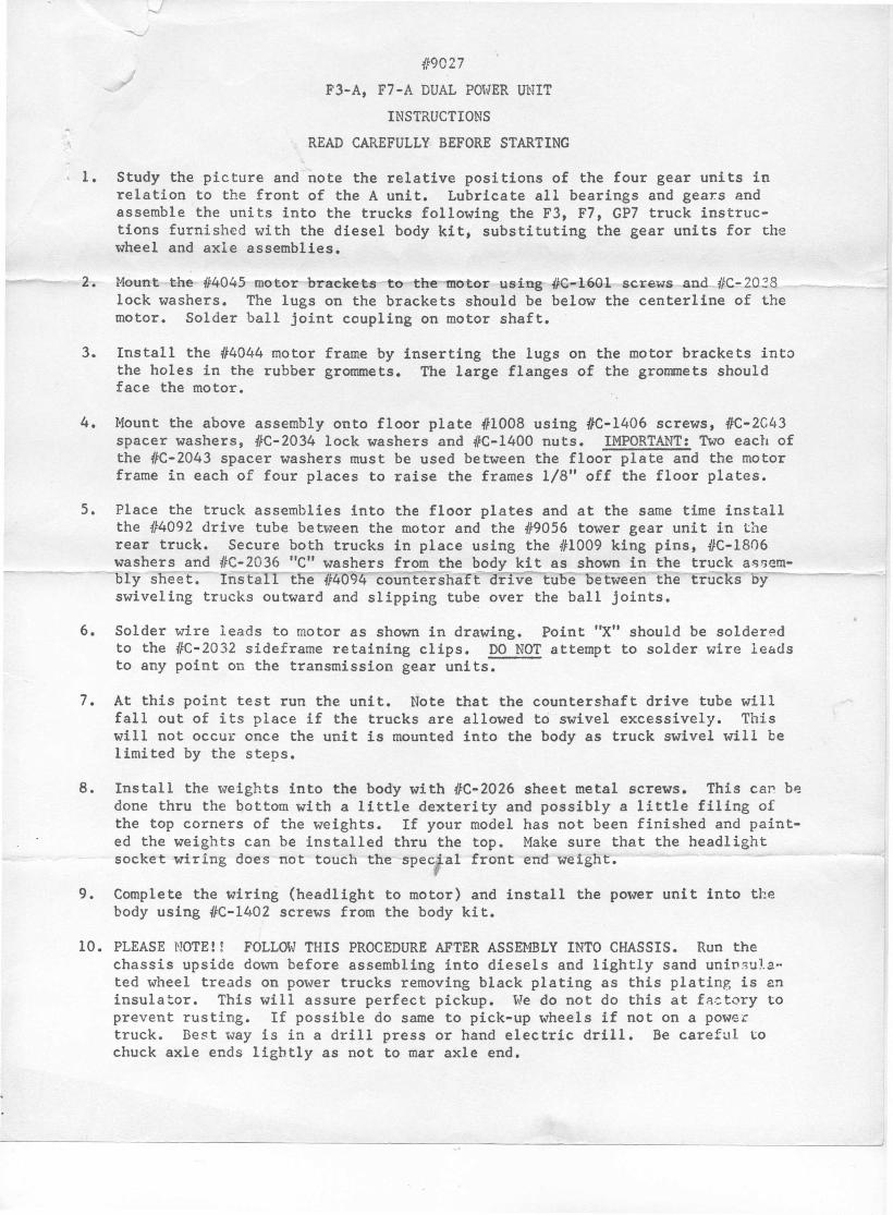
F3-A, F7-A DUAL POt-JERUNITINSTRUCTIONS
READ CAREFULLY BEFORE STARTING
1. Study the picture and note the relative positions of the four gear units inrelation to the front of the A unit. Lubricate all bearings and gear.s andassemble the units into the trucks following the F3, F7, GP7 truck instruc-tions furnished with the diesel body kit, substituting the gear units for thewheel and axle assemblies.
2. Hount the /f4045 motor brackets to the otor using 416-160-1screws an IFC-203Block washers. The lugs on the brackets should be below the centerline of themotor. Solder ball joint coupling on motor shaft.
3. Install the #4044 motor frame by inserting the lugs on the motor brackets intothe holes in the rubber grommets. The large flanges of the grommets shouldface the motor.
4. Mount the above assembly onto floor plate #1008 using #C-1406 screws, #C-2C43spacer washers, #C-2034 lock washers and #C-1400 nuts. IMPORTANT: Two each ofthe #C-2043 spacer washers must be used between the floor plate and the motorframe in each of four places to raise the frames 1/8" off the floor plates.
5. Place the truck assemblies into the floor plates and at the same time installthe 114092 drive tube be tween the motor and the 4f9056 tower gear uni t in therear truck. Secure both trucks in place using the #1009 king pins, #C-1806washers and #C-2036 "C" washers from the body kit as shown in the truck assem-bly sneet. Install toe #4094 countershatt drive tUDe oetween the trucks byswiveling trucks outward and slipping tube over the ball joints.
6. Solder wire leads to motor as shown in drawing. Point "X" should be solderedto the #C-2032 sideframe retaining clips. DO NOT attempt to solder wire le&dsto any point on the transmission gear units.
7. At this point test run the unit. Note that the countershaft drive tube willfallout of its place if the trucks are allowed to swivel excessively. Thiswill not occur once the unit is mounted into the body as truck swivel will belimited by the steps.
8. Install the weights into the body with #C-2026 sheet metal screws. This cap.b~done thru the bottom with a little dexterity and possibly a little filing ofthe top corners of the weights. If your model has not been finished and paint-ed the weights can be installed thru the top. Make sure that the headlightsocket wiring does not touch the "-Spec'a1 front end weight.
9. Complete the wiring (headlight to motor) and install the power unit into thebody using #C-l402 screws from the body kit.
10. PLEASE NOTE!! FOLLOliJTHIS PROCEDURE AFTER ASSEMBLY INTO CHASSIS. Run thechassis upside down before assembling into diesels and lightly sand unfnsu la-ted wheel treads on power trucks removing black plating as this plating is aninsulator. This will assure perfect pickup. We do not do this at factory toprevent rusting. If possible do same to pick-up wheels if not on a poweetruck. Best way is in a drill press or hand elec tric drill. Be careful tochuck axle ends lightly as not to mar axle end.
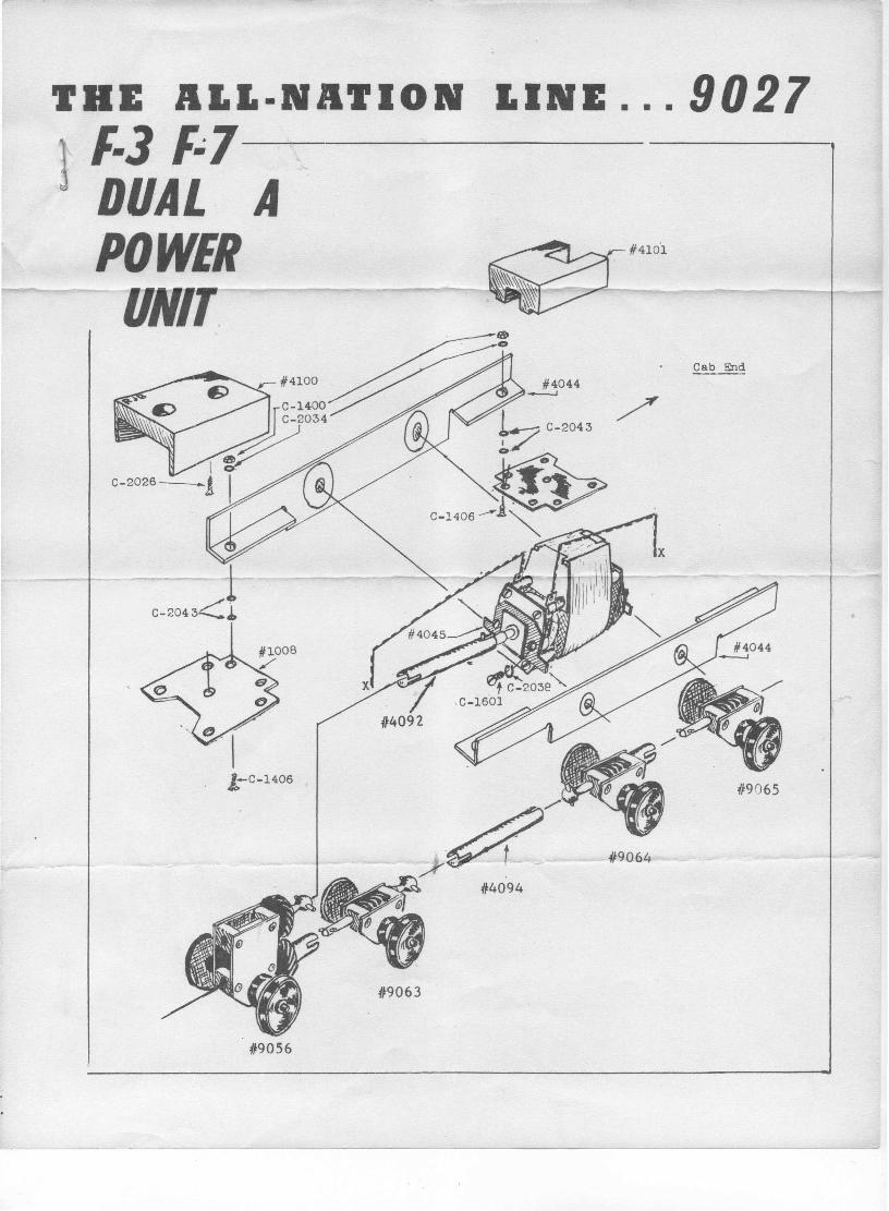
THE ALL·NATION LINE ... 9027.'-3 '~7--------'DUAL APO WER #410'1
ORIT.Cab End
#4044.----.J
!-C-1406
#9064
4~4094
t19063
. #9056
/
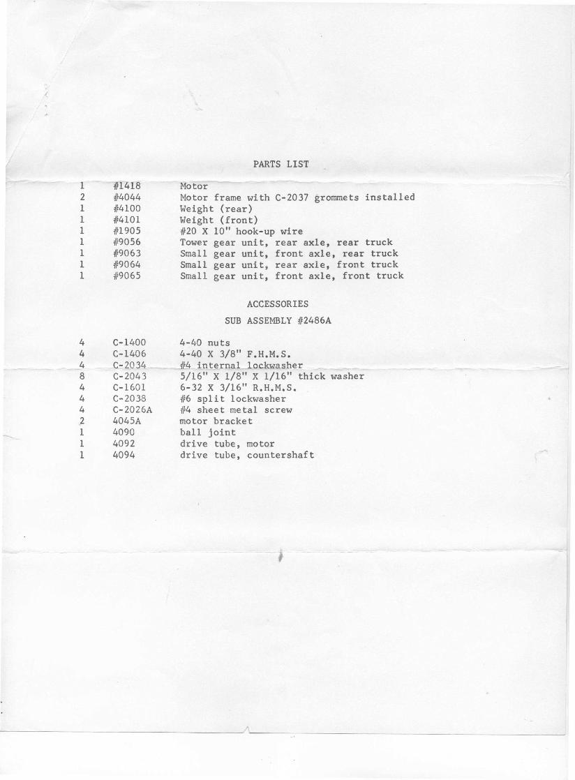
PARTS LIST
1 4Fl418 Motor2 #"4044 Motor frame with C-2037 grommets installed1 1[4100 Weight (rear)1 4/4101 Weight (front)1 {fl905 #20 X 10" hook-up wire1 419056 Tower gear unit, rear axle, rear truck1 :(/9063 Small gear unit, front axle, rear truck1 419064 Small gear unit, rear axle, front truck1 119065 Small gear uni t , front axle, front truck
ACCESSORIESSUB ASSEMBLY 412486A
4 C-1400 4-40 nuts4 C-1406 4-40 X 3/8" F.H.M.S.4 C-2034_ 4L4 internal lockwasher8 C-2043 5/16" X 1/8" X 1/16" thick washer4 C-1601 6-32 X 3/16" R.H.M.S.4 C-2038 416 split lockwasher4 C-2026A {f4 sheet metal screw.2 4045A motor bracket1 4090 ball joint1 4092 drive tube, motor1 4094 drive tube, countershaft
--------------------------------------~~~----~------------------------------------------~
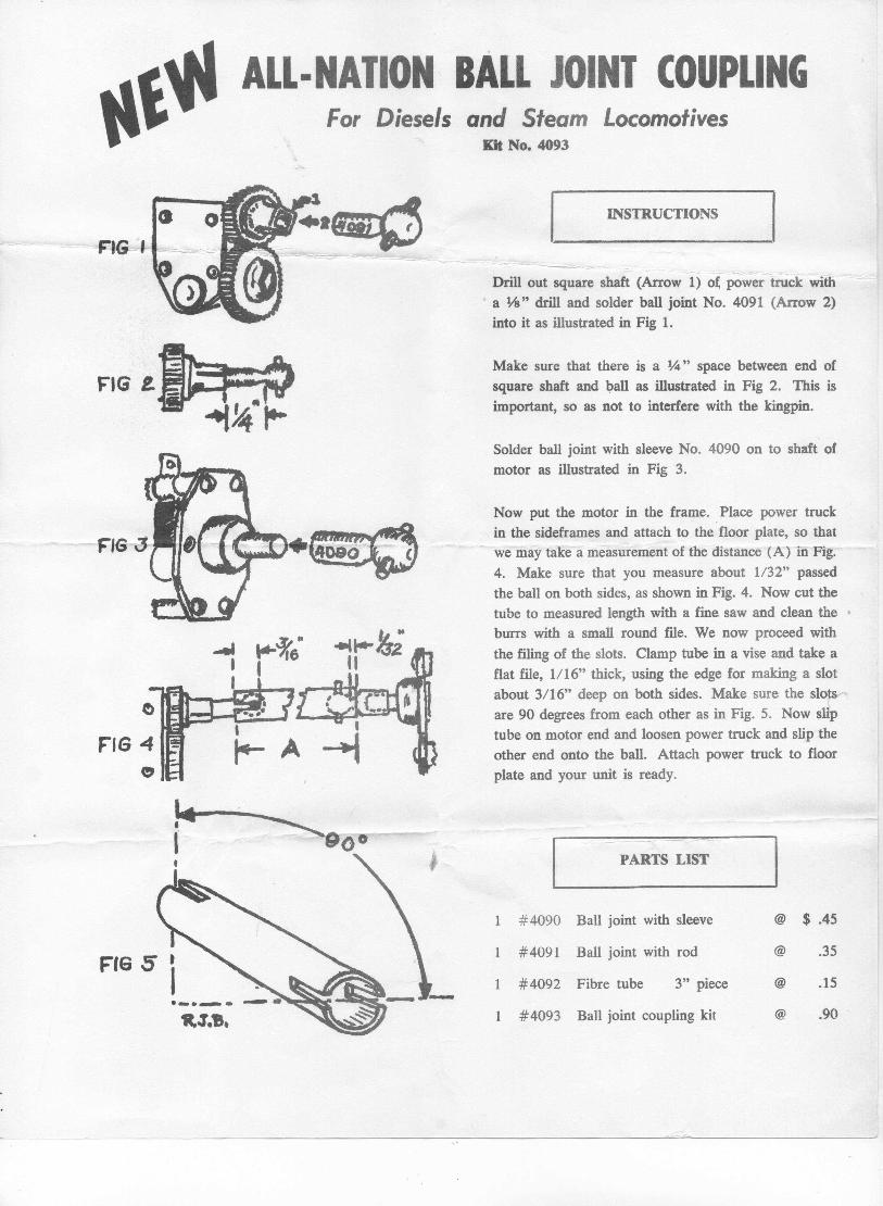
ALL·NATION BALL JOINT COUPLINGFor Diesels and Steam Locomotives
Kit No. 4093
1 #4090 Ball joint with sleeve @ $ .45
FIG 5 1 #4091 Ball joint with rod @ .35
1 #4092 Fibre tube 3" piece @ .15._ ..._,.'R,3.9. #4093 Ball joint coupling kit @ .90
FIG t.
INSTRUCTIONS
Drill out square shaft (Arrow i)o~~pO~er-trucK wlth--~=-a 1;8" drill and solder ball joint No. 4091 (Arrow 2)into it as illustrated in Fig 1.
Make sure that there is a ~" space between end ofsquare shaft and ball as illustrated in Fig 2. This isimportant, so as not to interfere with the kingpin.
Solder ball joint with sleeve No. 4090 on to shaft ofmotor as illustrated in Fig 3.
Now put the motor in the frame. Place power truckin the sideframes and attach to the floor plate, so thatwe may take a measurement of the distance (A) in Fig.4. Make sure that you measure about 1132" passedthe ball on both sides, as shown in Fig. 4. Now cut thetube to measured length with a fine saw and clean theburrs with a small round file. We now proceed withthe filing of the slots. Clamp tube in a vise and take aflat file, 1116" thick, using the edge for making a slotabout 3/16" deep on both sides. Make sure the slotsare 90 degrees from each other as in Fig. 5. Now sliptube on motor end and loosen power truck and slip theother end onto the ball. Attach power truck to floorplate and your unit is ready.
PARTS LIST