Assembly Instructions and Parts Manual JPSF-1 Fence and ...
12
Assembly Instructions and Parts Manual JPSF-1 Fence and JPSR Rail Set WALTER MEIER (Manufacturing) Inc. 427 New Sanford Road LaVergne, Tennessee 37086 Part No. M-708482 Ph.: 800-274-6848 Revision C2 02/2013 www.waltermeier.com Copyright © 2013 Walter Meier (Manufacturing) Inc.
Transcript of Assembly Instructions and Parts Manual JPSF-1 Fence and ...

Assembly Instructions and Parts Manual JPSF-1 Fence and JPSR Rail Set
WALTER MEIER (Manufacturing) Inc. 427 New Sanford Road LaVergne, Tennessee 37086 Part No. M-708482 Ph.: 800-274-6848 Revision C2 02/2013 www.waltermeier.com Copyright © 2013 Walter Meier (Manufacturing) Inc.
Tom Gauger
This .pdf document is bookmarked

2
Warranty and Service Walter Meier (Manufacturing) Inc., warrants every product it sells. If one of our tools needs service or repair, one of our Authorized Service Centers located throughout the United States can give you quick service. In most cases, any of these Walter Meier Authorized Service Centers can authorize warranty repair, assist you in obtaining parts, or perform routine maintenance and major repair on your JET® tools. For the name of an Authorized Service Center in your area call 1-800-274-6848. MORE INFORMATION Walter Meier is consistently adding new products to the line. For complete, up-to-date product information, check with your local Walter Meier distributor, or visit waltermeier.com. WARRANTY JET products carry a limited warranty which varies in duration based upon the product (MW = Metalworking, WW = Woodworking).
WHAT IS COVERED? This warranty covers any defects in workmanship or materials subject to the exceptions stated below. Cutting tools, abrasives and other consumables are excluded from warranty coverage. WHO IS COVERED? This warranty covers only the initial purchaser of the product. WHAT IS THE PERIOD OF COVERAGE? The general JET warranty lasts for the time period specified in the product literature of each product. WHAT IS NOT COVERED? Five Year Warranties do not cover woodworking (WW) products used for commercial, industrial or educational purposes. Woodworking products with Five Year Warranties that are used for commercial, industrial or education purposes revert to a One Year Warranty. This warranty does not cover defects due directly or indirectly to misuse, abuse, negligence or accidents, normal wear-and-tear, improper repair or alterations, or lack of maintenance. HOW TO GET SERVICE The product or part must be returned for examination, postage prepaid, to a location designated by us. For the name of the location nearest you, please call 1-800-274-6848. You must provide proof of initial purchase date and an explanation of the complaint must accompany the merchandise. If our inspection discloses a defect, we will repair or replace the product, or refund the purchase price, at our option. We will return the repaired product or replacement at our expense unless it is determined by us that there is no defect, or that the defect resulted from causes not within the scope of our warranty in which case we will, at your direction, dispose of or return the product. In the event you choose to have the product returned, you will be responsible for the shipping and handling costs of the return. HOW STATE LAW APPLIES This warranty gives you specific legal rights; you may also have other rights which vary from state to state. LIMITATIONS ON THIS WARRANTY WALTER MEIER (MANUFACTURING) INC., LIMITS ALL IMPLIED WARRANTIES TO THE PERIOD OF THE LIMITED WARRANTY FOR EACH PRODUCT. EXCEPT AS STATED HEREIN, ANY IMPLIED WARRANTIES OR MERCHANTABILITY AND FITNESS ARE EXCLUDED. SOME STATES DO NOT ALLOW LIMITATIONS ON HOW LONG THE IMPLIED WARRANTY LASTS, SO THE ABOVE LIMITATION MAY NOT APPLY TO YOU. WALTER MEIER SHALL IN NO EVENT BE LIABLE FOR DEATH, INJURIES TO PERSONS OR PROPERTY, OR FOR INCIDENTAL, CONTINGENT, SPECIAL, OR CONSEQUENTIAL DAMAGES ARISING FROM THE USE OF OUR PRODUCTS. SOME STATES DO NOT ALLOW THE EXCLUSION OR LIMITATION OF INCIDENTAL OR CONSEQUENTIAL DAMAGES, SO THE ABOVE LIMITATION OR EXCLUSION MAY NOT APPLY TO YOU. Walter Meier sells through distributors only. The specifications in Walter Meier catalogs are given as general information and are not binding. Members of Walter Meier reserve the right to effect at any time, without prior notice, those alterations to parts, fittings, and accessory equipment which they may deem necessary for any reason whatsoever. JET® branded products are not sold in Canada by Walter Meier.

3
Table of Contents Warranty and Service .............................................................................................................................. 2 Table of Contents .................................................................................................................................... 3 Unpacking ............................................................................................................................................... 4
Contents of the Shipping Container ...................................................................................................... 4 Assembly and Adjustments ...................................................................................................................... 4
Installing Rails ...................................................................................................................................... 4 Wood Extension Table (Optional) ......................................................................................................... 6 Installing the Fence .............................................................................................................................. 7 Attaching the Scale .............................................................................................................................. 8
Replacement Parts .................................................................................................................................. 9 52” & 30” Pro Shop Rail Set ............................................................................................................... 10 Parts List for the 52” & 30” Pro Shop Rail Set ..................................................................................... 11 Parts List for the JPSF-1 Pro Shop Fence .......................................................................................... 12
Stock No. Product 708482 ................................................................................................................. JPSF-1 ProShop Fence 708483 ..................................................................................................... JPSR-30, ProShop Rail Set, 30” 708484 ..................................................................................................... JPSR-52, ProShop Rail Set, 52”

4
Unpacking Open shipping container and check for shipping damage. Report any damage immediately to your distributor and shipping agent. Do not discard any shipping material until the Fence and Rails are assembled and working properly.
Compare the contents of your container with the following parts list to make sure all parts are intact. Missing parts, if any, should be reported to your distributor. Read the instruction manual thoroughly for assembly, maintenance and safety instructions.
Contents of the Shipping Container (shown in Figures 1 and 2) 1 ProShop Fence – A 1 Handle – B 1 Rear Rail – C 1 Front Rail – D 1 Guide Tube – E 1 Scale – F* 2 End Cover – G 1 Hardware Package – (Figure 2) 1 Owner's Manual 1 Warranty Card * located inside Guide Tube (E)
Assembly and Adjustments Tools required for assembly:
Cross Point (Phillips) Screwdriver Hex wrenches – 4mm and 6mm Open End Wrenches – 12mm and 13mm Electric Drill with 3/16” and 5/16” drill bits (for
optional wood extension table only) (4) C-Clamps, 4” to 6” (for optional wood
extension table only)
Disconnect table saw from power source before attempting any assembly or adjustment.
Installing Rails Refer to the exploded view on page 11 for any clarification of part positions.
1. Place the rear rail against the back edge of the table, making sure the notches in the rail are properly oriented. See Figure 3.
2. On the JPS-10TS table saw, insert four M8x35 socket head cap screws with M8 flat washers (plus M8 lock washers on the two inner screws).
Figure 1
Figure 2
(NOTE: These are not to scale)

5
NOTE: On the JTAS-10 table saw, use 5/16 x 1-1/4 socket head cap screws for the two inner screws.
3. Secure the two outer screws with a flat washer, lock washer and hex nut behind the lip of the saw table. Only finger tighten all nuts and screws.
4. The rear rail must be parallel to the table top to ensure proper fence operation. Measure the distance from the rail to the table surface at several points along the table. A sliding combination square is handy for this, as shown in Figure 4. All measurements should be the same. There is slight adjustment in the rail holes to allow for achieving parallelism with the table surface.
5. When the rear rail is parallel with the table surface, securely tighten all screws and nuts along the length of the rail.
6. Place the front rail against the front edge of the table, and insert four M8x35 socket flat head screws through the countersunk holes in the rail. Secure the two outer screws with a flat washer, lock washer and hex nut behind the lip of the table extensions. See Figure 5.
NOTE: On the JPS-10TS table saw, the two inner screws will thread into the table top without further need of fasteners. On the JTAS-10 table saw, the two inner screws will need flat washer, lock washer and hex nut inside the lip of the table.
7. Mount the table saw control switch to the threaded holes in the bottom of the front rail using the fasteners that came with the saw. See Figure 6.
NOTE: If you are installing an optional wood extension table, install it before mounting the guide tube. See “Wood Extension Table (Optional)”.
8. Remove the scale from inside the guide tube, and place the black end cap on the guide tube.
9. Align the holes in the guide tube with those in the front rail. The edge of the guide tube near which the holes are positioned should face toward the table saw. Insert seven M8x16 hex cap screws, lock washers and flat washers. See Figure 5. Finger tighten only until all screws are inserted, then tighten all screws. Be careful not to strip the holes while tightening.
Figure 3
Figure 4
Figure 5
Figure 6
6
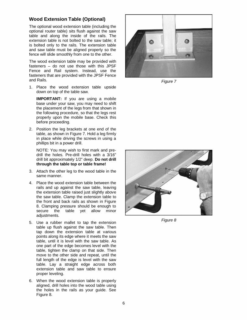
Wood Extension Table (Optional) The optional wood extension table (including the optional router table) sits flush against the saw table and along the inside of the rails. The extension table is not bolted to the saw table; it is bolted only to the rails. The extension table and saw table must be aligned properly so the fence will slide smoothly from one to the other.
The wood extension table may be provided with fasteners – do not use those with this JPSF Fence and Rail system. Instead, use the fasteners that are provided with the JPSF Fence and Rails.
1. Place the wood extension table upside down on top of the table saw.
IMPORTANT: If you are using a mobile base under your saw, you may need to shift the placement of the legs from that shown in the following procedure, so that the legs rest properly upon the mobile base. Check this before proceeding.
2. Position the leg brackets at one end of the table, as shown in Figure 7. Hold a leg firmly in place while driving the screws in using a phillips bit in a power drill.
NOTE: You may wish to first mark and pre-drill the holes. Pre-drill holes with a 3/16” drill bit approximately 1/2” deep. Do not drill through the table top or table frame!
3. Attach the other leg to the wood table in the same manner.
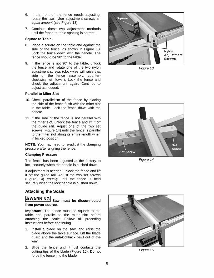
4. Place the wood extension table between the rails and up against the saw table, leaving the extension table raised just slightly above the saw table. Clamp the extension table to the front and back rails as shown in Figure 8. Clamping pressure should be enough to secure the table yet allow minor adjustments.
5. Use a rubber mallet to tap the extension table up flush against the saw table. Then tap down the extension table at various points along its edge where it meets the saw table, until it is level with the saw table. As one part of the edge becomes level with the table, tighten the clamp on that side. Then move to the other side and repeat, until the full length of the edge is level with the saw table. Lay a straight edge across both extension table and saw table to ensure proper leveling.
6. When the wood extension table is properly aligned, drill holes into the wood table using the holes in the rails as your guide. See Figure 8.
Figure 7
Figure 8

7
(You may wish to drill 3/32" pilot holes first.) Drill 8mm (5/16”) holes into the front edge of the table using the holes in the front rail as a guide. Drill 8mm (5/16") holes into the back edge of the table using the holes in the rear rail as a guide.
7. Install M8 x 35 socket flat head screws through the front rail and secure each with a flat washer, lock washer, and hex nut behind the lip of the wood table (Figure 9). Finger tighten only.
8. Install M8 x 35 socket head cap screws and flat washers in the rear rail, and secure with flat washer, lock washer and hex nut behind the lip of the wood table (Figure 10). Finger tighten only.
9. Re-check the table for alignment, make further adjustments if necessary, then tighten all screws and nuts.
10. Rotate the footpads on the legs until they reach the floor, then tighten the hex nuts.
11. Proceed to step 6 on page 5 to assemble the guide rail.
Installing the Fence 1. Thread the handle into the hole on the
fence.
2. Lift handle all the way up and place the fence onto the rails. There are three positions of the handle: The up position for mounting and removing the fence; middle position for sliding the fence along the rails; and the down position for locking the fence in place. Push the handle down firmly when locking the fence in place.
Several adjustments are necessary before using the fence for ripping wood; follow these steps in the order in which they are presented. Level with Saw Table
3. Lock the fence on the guide rail.
4. View the fence from the left or right side of the saw. There should be a small space between the table surface and the fence bottom, to prevent the fence from dragging on the saw table. This space should be equal along the entire length of the fence, as shown in Figure 11.
5. If this space is not equal, unlock the fence and turn it over. Loosen the hex nut under the adjustment foot (Figure 12) and rotate the adjustment foot as needed to raise or lower the rear of the fence. Tighten the hex nut and re-position the fence to check the spacing.
Figure 9
Figure 10
Figure 11
Figure 12
8
6. If the front of the fence needs adjusting, rotate the two nylon adjustment screws an equal amount (see Figure 13).
7. Continue these two adjustment methods until the fence-to-table spacing is correct.
Square to Table 8. Place a square on the table and against the
side of the fence, as shown in Figure 13. Lock the fence down with the handle. The fence should be 90° to the table.
9. If the fence is not 90° to the table, unlock the fence and rotate one of the two nylon adjustment screws (clockwise will raise that side of the fence assembly, counter-clockwise will lower). Lock the fence and check the adjustment again. Continue to adjust as needed.
Parallel to Miter Slot 10. Check parallelism of the fence by placing
the side of the fence flush with the miter slot in the table. Lock the fence down with the handle.
11. If the side of the fence is not parallel with the miter slot, unlock the fence and lift it off the guide rail. Adjust one of the two set screws (Figure 14) until the fence is parallel to the miter slot along its entire length when in locked position.
NOTE: You may need to re-adjust the clamping pressure after aligning the fence.
Clamping Pressure
The fence has been adjusted at the factory to lock securely when the handle is pushed down.
If adjustment is needed, unlock the fence and lift if off the guide rail. Adjust the two set screws (Figure 14) equally until the fence is held securely when the lock handle is pushed down.
Attaching the Scale
Saw must be disconnected from power source. Important: The fence must be square to the table and parallel to the miter slot before attaching the scale. Follow all preceding instructions before continuing.
1. Install a blade on the saw, and raise the blade above the table surface. Lift the blade guard and the anti-kickback pawl out of the way.
2. Slide the fence until it just contacts the cutting tips of the blade (Figure 15). Do not force the fence into the blade.
Figure 13
Figure 14
Figure 15
9
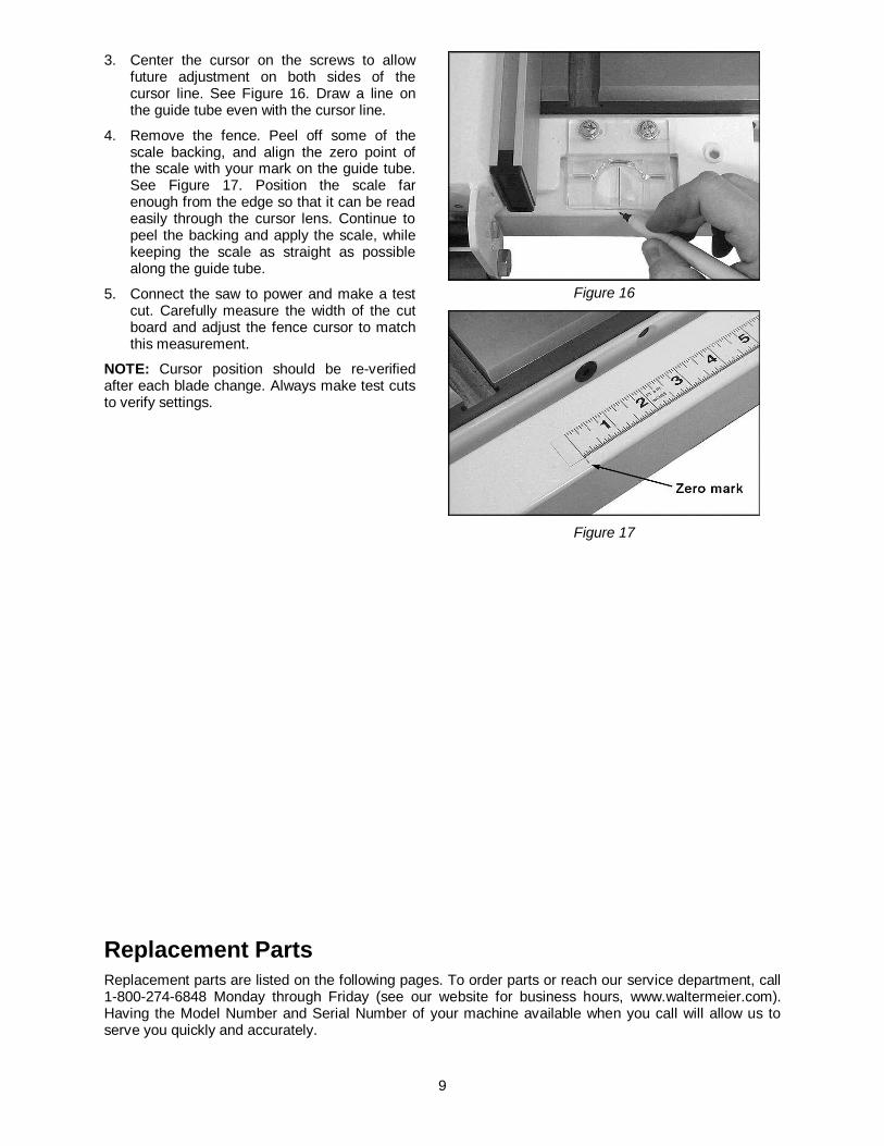
3. Center the cursor on the screws to allow future adjustment on both sides of the cursor line. See Figure 16. Draw a line on the guide tube even with the cursor line.
4. Remove the fence. Peel off some of the scale backing, and align the zero point of the scale with your mark on the guide tube. See Figure 17. Position the scale far enough from the edge so that it can be read easily through the cursor lens. Continue to peel the backing and apply the scale, while keeping the scale as straight as possible along the guide tube.
5. Connect the saw to power and make a test cut. Carefully measure the width of the cut board and adjust the fence cursor to match this measurement.
NOTE: Cursor position should be re-verified after each blade change. Always make test cuts to verify settings.
Figure 16
Figure 17
Replacement Parts Replacement parts are listed on the following pages. To order parts or reach our service department, call 1-800-274-6848 Monday through Friday (see our website for business hours, www.waltermeier.com). Having the Model Number and Serial Number of your machine available when you call will allow us to serve you quickly and accurately.

10
52” & 30” Pro Shop Rail Set

11
Parts List for the 52” & 30” Pro Shop Rail Set
Index No. Part No. Description Size Qty ................. 708484 ....................JPSR-52: 52” Pro Shop Rail Set .............................................................. ................. 708483 ....................JPSR-30: 30” Pro Shop Rail Set .............................................................. 1 ............... JPSR52-101 ............52” Guide Tube ..................................................................................... 1 ................. JPSR30-101 ............30” Guide Tube ..................................................................................... 1 2 ............... JPSR52-102 ............52” Front Rail......................................................................................... 1 ................. JPSR30-102 ............30” Front Rail......................................................................................... 1 3 ............... JPSR52-103 ............52” Rear Rail ......................................................................................... 1 ................. JPSR30-103 ............30” Rear Rail ......................................................................................... 1 4 ............... JPSR30-104 ............End Cover ............................................................................................. 2 5 ............... TS-1490021 .............Hex Cap Screw ..................................................M8x16 ........................ 7 6 ............... TS-2361081 .............Lock Washer ......................................................M8 ............................ 21 7 ............... JPSR30-107 ............Flat Head Socket Screw .....................................M8x35 ........................ 7 8 ............... TS-1540061 .............Hex Nut ..............................................................M8 ............................ 12 9 ............... TS-1504071 .............Socket Head Cap Screw .....................................M8x35 ........................ 7 10 ............. JPSR52-110 ............52” Scale ............................................................................................... 1 ................. JPSR30-110 ............30” Scale ............................................................................................... 1 11 ............. TS-1550061 .............Flat Washer ........................................................M8 ............................ 26 12 ............. TS-0208071 .............Socket Head Cap Screw (for JTAS-10 only) ........5/16”-18x1-1/4” ........... 2 ................. JPSR-RHP ...............Rail Hardware Package (not shown) ............ ...........................................
12
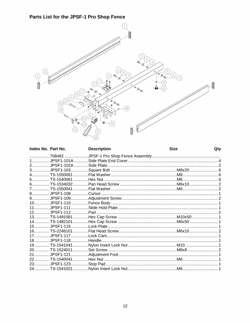
Parts List for the JPSF-1 Pro Shop Fence
Index No. Part No. Description Size Qty ................. 708482 ....................JPSF-1 Pro Shop Fence Assembly .......................................................... 1 ............... JPSF1-101A ............Side Plate End Cover ............................................................................ 4 2 ............... JPSF1-102A ............Side Plate .............................................................................................. 2 3 ............... JPSF1-103 ...............Square Bolt ........................................................M8x20 ........................ 6 4 ............... TS-1550061 .............Flat Washer ........................................................M8 .............................. 6 5 ............... TS-1540061 .............Hex Nut ..............................................................M8 .............................. 6 6 ............... TS-1534032 .............Pan Head Screw ................................................M6x10 ........................ 2 7 ............... TS-1550041 .............Flat Washer ........................................................M6 .............................. 2 8 ............... JPSF1-108 ...............Cursor ................................................................................................... 1 9 ............... JPSF1-109 ...............Adjustment Screw.................................................................................. 2 10 ............. JPSF1-110 ...............Fence Body ........................................................................................... 1 11 ............. JPSF1-111 ...............Slide Hold Plate ..................................................................................... 1 12 ............. JPSF1-112 ...............Pad ....................................................................................................... 2 13 ............. TS-1491081 .............Hex Cap Screw ..................................................M10x50 ...................... 1 14 ............. TS-1482101 .............Hex Cap Screw ..................................................M6x50 ........................ 1 15 ............. JPSF1-115 ...............Lock Plate ............................................................................................. 1 16 ............. TS-2246101 .............Flat Head Screw .................................................M6x10 ........................ 2 17 ............. JPSF1-117 ...............Lock Cam .............................................................................................. 1 18 ............. JPSF1-118 ...............Handle................................................................................................... 1 19 ............. TS-1541041 .............Nylon Insert Lock Nut .........................................M10 ............................ 1 20 ............. TS-1524011 .............Set Screw ...........................................................M8x8 .......................... 2 21 ............. JPSF1-121 ...............Adjustment Foot .................................................................................... 1 22 ............. TS-1540041 .............Hex Nut ..............................................................M6 .............................. 1 23 ............. JPSF1-123 ...............Stop Pad ............................................................................................... 1 24 ............. TS-1541021 .............Nylon Insert Lock Nut .........................................M6 .............................. 1