Assembly Instructions - · PDF fileStep 1: Insert 5/8” hitch pin spring block into end...
9
Assembly Instructions
Transcript of Assembly Instructions - · PDF fileStep 1: Insert 5/8” hitch pin spring block into end...

Assembly Instructions
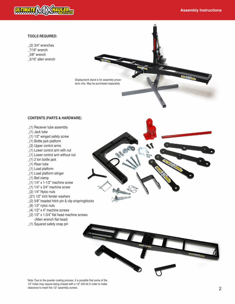
TOOLS REQUIRED:
_(2) 3/4” wrenches_7/16” wrench_3/8” wrench_5/16” allen wrench
CONTENTS (PARTS & HARDWARE)
_(1) Receiver tube assembly_(1) Jack tube_(1) 1/2” winged safety screw_(1) Bottle jack platform_(2) Upper control arms_(1) Lower control arm with nut_(1) Lower control arm without nut_(1) 2 ton bottle jack_(1) Riser tube_(1) Load platform_(1) Load platform stinger_(1) Bell clamp_(1) 1/4” x 1-1/2” machine screw_(1) 1/4” x 3/4” machine screw _(2) 1/4” Nyloc nuts_(21) 1⁄2” inch fender washers_(2) 5/8” treaded hitch pin & clip w/springblocks_(6) 1/2” nyloc nuts_(4) 1/2” x 4” machine screws_(2) 1/2” x 1-3/4” flat head machine screws (Allen wrench flat head)_(1) Squared safety snap pin
Note: Due to the powder coating process, it is possible that some of the 1⁄2” holes may require being chased with a 1⁄2” drill bit in order to make clearance to insert the 1⁄2” assembly screws.
Display/work stand is for assembly proce-dure only. May be purchased separately.
Assembly Instructions
2

Step 1: Insert 5/8” hitch pin spring block into end of receiver tube assembly and align hole with 5/8” hole on side of receiver tube. Insert receiver tube assembly into a hitch receiver and insert hitch retaining pin. This step is meant to keep everything stable for assembly.
Step 2: Lay out jack platform and lower control arms as shown in picture. Note the orientation of the arm with the nut and the ear on the jack platform. Insert the 2-1/2” x 1-3/4” flat head(allen head) machine screws into the recessed(chamfered) holes on the lower control arms, slide a 1⁄2” fender washer on each, insert into holes on jack platform, slide another 1⁄2” fender washer on each screw, and put on the two 1⁄2” nyloc nuts. Tighten the two nyloc nuts to a snug fit but not too tight. You should be able to rotate the control arms on the jack platform with only a moderate amount of friction between the two.
Step 3: Slide the assembly completed in step 2 over the receiver tube as shown in the picture. Note orientation of jack platform ear with receiver tube.
Assembly Instructions
3

Step 4: For this step you will use 1-1/2” x 4” machine screw and4-1/2” fender washers and one nyloc nut. Slide a washer onto screw and insert screw through upper hole in lower control arm, insert another fender washer between control arm and receiver tube, push screw through hole on other side of receiver tube, insert another fender washer between opposite control arm and receiver tube, and then push screw through hole in other control arm. Put another washer on end of screw and attach 1⁄2” nyloc nut. Just spin on nut by hand until it stops-you will be tightening all the control arm nuts later.
Step 6: Attach riser tube to control arms as illustrated in picture. You can attach riser tube to control arms using either the upper, middle or lower sets of holes in the riser tube. We recommend starting off using the lowest set of holes and adjusting to higher holes if loading ramp does not go all the way to the ground for loading. Use same sequence of instructions as step 4. Now you can tighten the four control arm pivot bolts until snug and then back off about 1/8” turn.
Assembly Instructions
Step 7: Attach bell clamp to jack platform using 1/4” x 3/4” machine screw and 1/4” nyloc nut and tighten just a little so that clamp can still rotate on jack platform with a moderate amount of force.
4
Step 5: Attach upper control arms to the receiver tube using same sequence of instructions as step 4. Do not tighten nuts yet. Also, make sure the orientation of the stickers are correct.

Assembly Instructions
Step 8: Slide bottle jack into bell clamp and insert 1/4” x 1-1/2” machine screw and attach 1/4” nyloc nut and tighten just a little but not fully tight yet.
Step 9: Lift riser tube by hand and swing bottle jack towards vertical part of receiver tube and insert top of bottle jack into retaining ring on top of receiver tube. Apply some down force onto riser tube to seat bottle jack and make sure bottle jack fits squarely on top of jack platform. Finish tightening 1/4” nyloc nut on jack platform and bell clamp to secure bottle jack.
Step 10: With jack fully compressed, open jack bleed screw 1/2” turn and pup jack handle up and down in full strokes about 20 times to bleed any air out of the jack that may have entered during shipping. Close bleed screw and completely jack up the riser tube to the full up position and insert 1/2” winged safety screw with 1/2” fender washer.
Step 12: Congratulations, you are almost ready to use your Ultimate MX Hauler, but before you do, please read all the safety instructions and user instructions first.
5
Step 11:Put second threaded hitch pin spring block into end of 2” platform tube and align with 5/8” hole.

Warnings and Precautions
- Make sure motorcycle does not obscure your rearward vision while driving vehicle.
- If taillights of vehicle used to haul motorcycle are obscured, take appropriate action to remedy this situation.
- Do not overload vehicle or trailer receiver load capacities.
- Check all carrier nuts and bolts for proper tightness before each use and every one hundred miles thereafter. Nuts on pivot points should be adjusted to zero clearance or free play.
- This rack is designed for typical use and applications (on paved or smooth gravel roads). Do not use this rack on a vehicle that will be driven on rough roads or where the rack (and motorcycle) will be subject to significant or constant jarring and/or shock, or any vehicle with very stiff springs that will transfer the load shock directly to the rack and motorcycle.
- Proper fitting and installation of this carrier to your specific vehicle is critical, and is not the manufacturer’s responsibility.
- Improper use of this product may result in damage to your carrier, your vehicle, your motorcycle, or even other vehicles driving behind you (as a result of colliding with or trying to avoid fallen motorcycles and/or the carrier.
- The purchaser should be aware that the load created by a carrier and motorcycle can exceed the maximum rating on the hitch and or vehicle.
- Never transport with carrier rack in any position other than the full upright position, and with safety pin installed and tightened securely.
- Make sure motorcycle is securely attached to the load platform before jacking up the platform.
- Safety pin must be installed after carrier rack is raised to full upright position and prior to transport.
- Use jack handle to securely tighten winged safety screw.
- Always tighten hitch-stabilizing bolts with suitable wrench prior to loading motorcycle on carrier and insert safety pin clip.
- When lowering or raising load platform, the operator must stand between vehicle and motorcycle. Keep hands, feet, and arms away from all moving parts while jack is in operation.
- Do not allow anyone to stand on the left side (outside or rear most) of motorcycle during the raising or lowering operation. Motorcycle could drop very quickly and with great force causing serious injury or death to anyone standing on the left side of motorcycle (behind the load platform).
- When lowering motorcycle, open jack bleed valve very slowly in order to control the rate with witch the motorcycle is lowered. Failure to do so could result in the motorcycle lowering very rapidly and in an uncontrollable manner resulting in injury or death. Make sure no one is standing on the left side of motorcycle during this process.
- Check tightness of tie down straps and winged safety pin after first ten miles of transport and every one hundred miles thereafter.
- After reading this manual, should you have any additional questions regarding the compatibility, fitting, and/or use of this carrier, please call Ultimate MX Hauler customer service at 909-307-1954.
6
Instructions for Use
- Read all warnings and precautions before use (page 6).
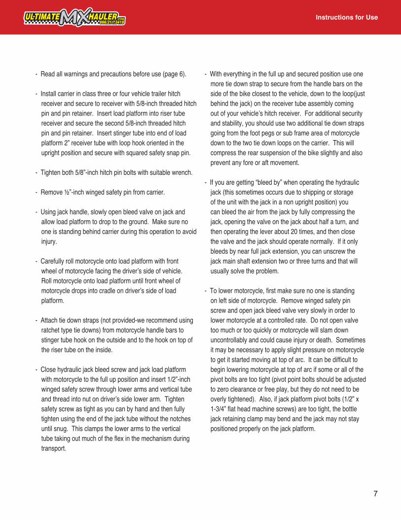
- Install carrier in class three or four vehicle trailer hitch receiver and secure to receiver with 5/8-inch threaded hitch pin and pin retainer. Insert load platform into riser tube receiver and secure the second 5/8-inch threaded hitch pin and pin retainer. Insert stinger tube into end of load platform 2” receiver tube with loop hook oriented in the upright position and secure with squared safety snap pin.
- Tighten both 5/8”-inch hitch pin bolts with suitable wrench.
- Remove ½”-inch winged safety pin from carrier.
- Using jack handle, slowly open bleed valve on jack and allow load platform to drop to the ground. Make sure no one is standing behind carrier during this operation to avoid injury.
- Carefully roll motorcycle onto load platform with front wheel of motorcycle facing the driver’s side of vehicle. Roll motorcycle onto load platform until front wheel of motorcycle drops into cradle on driver’s side of load platform.
- Attach tie down straps (not provided-we recommend using ratchet type tie downs) from motorcycle handle bars to stinger tube hook on the outside and to the hook on top of the riser tube on the inside.
- Close hydraulic jack bleed screw and jack load platform with motorcycle to the full up position and insert 1/2”-inch winged safety screw through lower arms and vertical tube and thread into nut on driver’s side lower arm. Tighten safety screw as tight as you can by hand and then fully tighten using the end of the jack tube without the notches until snug. This clamps the lower arms to the vertical tube taking out much of the flex in the mechanism during transport.
- With everything in the full up and secured position use one more tie down strap to secure from the handle bars on the side of the bike closest to the vehicle, down to the loop(just behind the jack) on the receiver tube assembly coming out of your vehicle’s hitch receiver. For additional security and stability, you should use two additional tie down straps going from the foot pegs or sub frame area of motorcycle down to the two tie down loops on the carrier. This will compress the rear suspension of the bike slightly and also prevent any fore or aft movement.
- If you are getting “bleed by” when operating the hydraulic jack (this sometimes occurs due to shipping or storage of the unit with the jack in a non upright position) you can bleed the air from the jack by fully compressing the jack, opening the valve on the jack about half a turn, and then operating the lever about 20 times, and then close the valve and the jack should operate normally. If it only bleeds by near full jack extension, you can unscrew the jack main shaft extension two or three turns and that will usually solve the problem.
- To lower motorcycle, first make sure no one is standing on left side of motorcycle. Remove winged safety pin screw and open jack bleed valve very slowly in order to lower motorcycle at a controlled rate. Do not open valve too much or too quickly or motorcycle will slam down uncontrollably and could cause injury or death. Sometimes it may be necessary to apply slight pressure on motorcycle to get it started moving at top of arc. It can be difficult to begin lowering motorcycle at top of arc if some or all of the pivot bolts are too tight (pivot point bolts should be adjusted to zero clearance or free play, but they do not need to be overly tightened). Also, if jack platform pivot bolts (1/2” x 1-3/4” flat head machine screws) are too tight, the bottle jack retaining clamp may bend and the jack may not stay positioned properly on the jack platform.
7

REMEMBER, THIS IS A PERFORMANCE PRODUCT. USE AT YOUR OWN RISK.
Do not use this product until you have carefully read the following agreement. This agreement sets forth the terms and conditions for use of this product. The installation of this product indicates that the buyer has read and understands all precautions, user instructions, and this agreement and accepts the terms and conditions.
MAINTENANCE- Before each use, check all nuts and bolts for proper tightness and check for any cracks on all welds and steel parts. Also
check for any bending of any parts.
- Lubricate threads on safety pin, and hitch pins with light oil. Also lubricate the lifting shaft and small pumping shaft on the bottle jack with oil.
- Store carrier in upright position in order to prevent air from entering bottle jack. Do not store in a wet environment or bottle jack shafts will rust and premature wear of the bottle jack seals will result.
- Make sure your tie down straps are in good condition.
- If powder coat should be scraped or scratched off of any part of carrier, remove any rust and touch up with a non water based paint.
DISCLAIMER OF LIABILITYUltimate MX Hauler, its distributors, jobbers, and dealers (hereafter Seller) shall be in no way responsible for the products proper use and service. THE BUYER HEREBY WAIVES ALL LIABILITY CLAIMS.
The Buyer acknowledges that he is not relying on the Sellers skill or judgment to select or furnish goods suitable for any particular purpose and that there are no liabilities which extend beyond the description on the face hereof, and the Buyer hereby waivers all remedies or liabilities expressed or implied, arising by law or otherwise, (including without any obligation of the Seller with respect to fitness, merchantability and consequential damages) or whether or not occasioned by the Seller’s negligence.
The Seller disclaims any warranty and expressly disclaims any liability for personal injury or damages. The Buyer acknowledges and agrees that the disclaimer of any liability for personal injury is a material term for this agreement and the Buyer agrees to indemnify the Seller and to hold the Seller harmless from any claim related to the item of the equipment purchases. Under no circumstances will the Seller be liable for any damages or expenses by reason of use or sale of any such equipment.
The Seller assumes no liability regarding the improper installation or misapplication of its products. It is the installer’s responsibility to check for proper installation and if in doubt contact the manufacturer.
The Buyer is solely responsible for all warranty issues from the manufacturer.
8
Maintenance, Disclaimer & Warranty

LIMITATION OF WARRANTYCENTINA INVESTMENTS, LLC., D.B.A. ULTIMATE MX HAULER (Hereafter Seller) gives Limited Warranty as to description, quality, merchantability, and fitness for any particular purpose, productiveness, or any other matter of Sellers product sold herewith. The Seller shall be in no way responsible for the products proper use and service and the Buyer hereby waives all rights other than those expressly written herein. This warranty shall not be extended, altered or varied except by a written instrument signed by Seller and Buyer.
The Warranty is Limited to one (1) year from the date of sale and limited solely to the parts contained within the products kit. All products that are in question of Warranty must be returned prepaid to the Seller and must be accompanied by a dated proof of purchase receipt. All Warranty claims are subject to approval by Ultimate MX Hauler. Any Ultimate MX Hauler product that is returned to us and is found by Ultimate MX Hauler to be defective will be repaired or replaced at the option of Ultimate MX Hauler. This Warranty is the sole and exclusive remedy. Seller shall not be held liable for any indirect, special, or consequential damages.
The Warranty does not apply to products which have not been properly installed and adjusted according to Ultimate MX Hauler installation instructions. The Warranty does not cover any product that has been subject to misuse or alteration. This warranty does not apply to damage to the product caused by a crash or abuse of the product or any other circumstances in which the product has been subjected to forces or loads beyond its design. This Warranty does not cover paint, coatings, rub strips, or modifications to the product.
Under no circumstances will the Seller be liable for any labor charged or travel time incurred in diagnosis for defects, removal, or reinstallation of this product or any other contingent expenses.
Under no circumstances will the Seller be liable for any damage or expenses incurred by reason of the use or sale of any such equipment.
IN THE EVENT THAT THE BUYER DOES NOT AGREE WITH THIS AGREEMENT: THE BUYER MAY PROMPTLY RETURN THIS PRODUCT, IN A NEW AND UNUSED CONDITION, WITH A DATED PROOF OF PURCHASE TO THE PLACE OF PURCHASE WITHIN TEN (10) DAYS FROM DATE OF PURCHASE FOR A FULL REFUND.
THE INSTALLATION OF THIS PRODUCT INDICATES THAT THE BUYER HAS READ AND UNDERSTANDS THIS AGREEMENT AND ACCEPTS ITS TERMS AND CONDITIONS.
9
Maintenance, Disclaimer & Warranty
Maintenance, Disclaimer & Warranty