Assembly Instruction for Fiber Optic Series FOH Fischer ... · Push the contact bloc (termini...
23
Assembly Instruction for Fiber Optic Series FOH Fischer Connectors
Transcript of Assembly Instruction for Fiber Optic Series FOH Fischer ... · Push the contact bloc (termini...
Assembly Instruction for Fiber Optic Series FOH
Fischer Connectors

Assembly instructions Rev 6.0
2 This document is the property of Fischer Connectors.
This document must not be reproduced or distributed, in whole or in part, without prior written permission of Fischer Connectors.
Table des matières 1 Introduction .............................................................................................................................................................. 3
2 Document history ..................................................................................................................................................... 3
3 Definitions and Acronyms ......................................................................................................................................... 3
4 FOH Plugs & Receptacles with Potting Set ................................................................................................................ 4
5 FOH R01, R03 & R13 Receptacles with Wire Set ....................................................................................................... 9
6 Terminus assembly ................................................................................................................................................. 12
7 Polishing .................................................................................................................................................................. 14
8 Appendix ................................................................................................................................................................. 22
Assembly instructions Rev 6.0
3 This document is the property of Fischer Connectors.
This document must not be reproduced or distributed, in whole or in part, without prior written permission of Fischer Connectors.
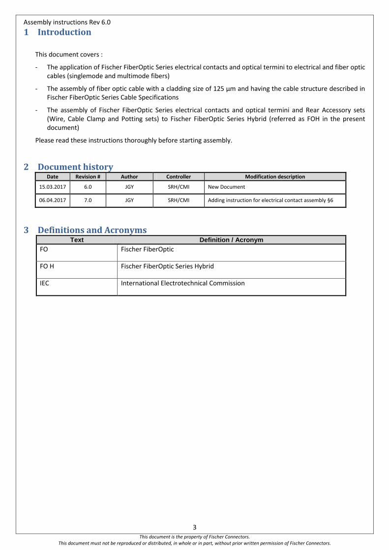
1 Introduction
This document covers :
- The application of Fischer FiberOptic Series electrical contacts and optical termini to electrical and fiber optic cables (singlemode and multimode fibers)
- The assembly of fiber optic cable with a cladding size of 125 µm and having the cable structure described in Fischer FiberOptic Series Cable Specifications
- The assembly of Fischer FiberOptic Series electrical contacts and optical termini and Rear Accessory sets (Wire, Cable Clamp and Potting sets) to Fischer FiberOptic Series Hybrid (referred as FOH in the present document)
Please read these instructions thoroughly before starting assembly.
2 Document history Date Revision # Author Controller Modification description
15.03.2017 6.0 JGY SRH/CMI New Document
06.04.2017 7.0 JGY SRH/CMI Adding instruction for electrical contact assembly §6
3 Definitions and Acronyms Text Definition / Acronym
FO Fischer FiberOptic
FO H Fischer FiberOptic Series Hybrid
IEC International Electrotechnical Commission
Assembly instructions Rev 6.0
4 This document is the property of Fischer Connectors.
This document must not be reproduced or distributed, in whole or in part, without prior written permission of Fischer Connectors.
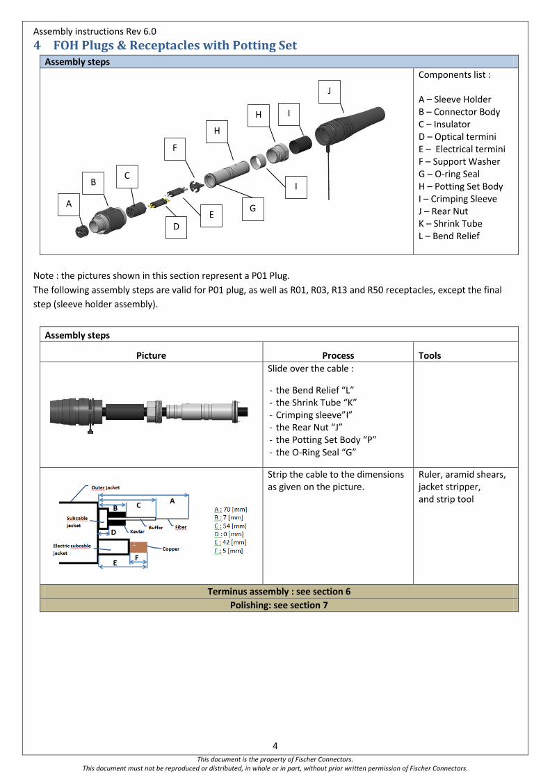
4 FOH Plugs & Receptacles with Potting Set Assembly steps
Components list : A – Sleeve Holder B – Connector Body C – Insulator D – Optical termini E – Electrical termini F – Support Washer G – O-ring Seal H – Potting Set Body I – Crimping Sleeve J – Rear Nut K – Shrink Tube L – Bend Relief
Note : the pictures shown in this section represent a P01 Plug.
The following assembly steps are valid for P01 plug, as well as R01, R03, R13 and R50 receptacles, except the final
step (sleeve holder assembly).
Assembly steps
Picture Process Tools
Slide over the cable :
- the Bend Relief “L” - the Shrink Tube “K” - Crimping sleeve”I” - the Rear Nut “J” - the Potting Set Body “P” - the O-Ring Seal “G”
Strip the cable to the dimensions as given on the picture.
Ruler, aramid shears, jacket stripper, and strip tool
Terminus assembly : see section 6
Polishing: see section 7
A
B C
D E
G
I
H I
J
F
H
Assembly instructions Rev 6.0
5 This document is the property of Fischer Connectors.
This document must not be reproduced or distributed, in whole or in part, without prior written permission of Fischer Connectors.
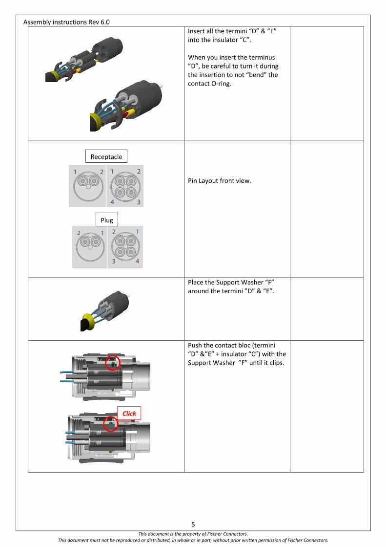
Insert all the termini “D” & ”E” into the insulator “C”. When you insert the terminus ”D”, be careful to turn it during the insertion to not “bend” the contact O-ring.
Pin Layout front view.
Place the Support Washer “F” around the termini ”D” & “E”.
Push the contact bloc (termini “D” &”E” + insulator “C”) with the Support Washer ”F” until it clips.
Receptacle
Plug
Click
Assembly instructions Rev 6.0
6 This document is the property of Fischer Connectors.
This document must not be reproduced or distributed, in whole or in part, without prior written permission of Fischer Connectors.
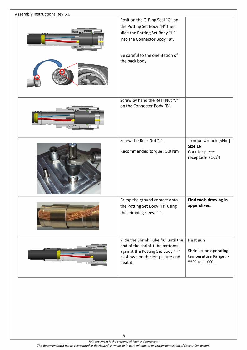
Position the O-Ring Seal “G” on
the Potting Set Body “H” then
slide the Potting Set Body “H”
into the Connector Body "B".
Be careful to the orientation of the back body.
Screw by hand the Rear Nut “J” on the Connector Body “B”.
Screw the Rear Nut "J".
Recommended torque : 5.0 Nm
Torque wrench [5Nm] Size 16 Counter piece: receptacle FO2/4
Crimp the ground contact onto
the Potting Set Body “H” using
the crimping sleeve”I” .
Find tools drawing in appendixes.
Slide the Shrink Tube "K" until the end of the shrink tube bottoms against the Potting Set Body “H” as shown on the left picture and heat it.
Heat gun
Shrink tube operating temperature Range : -55°C to 110°C..
Assembly instructions Rev 6.0
7 This document is the property of Fischer Connectors.
This document must not be reproduced or distributed, in whole or in part, without prior written permission of Fischer Connectors.
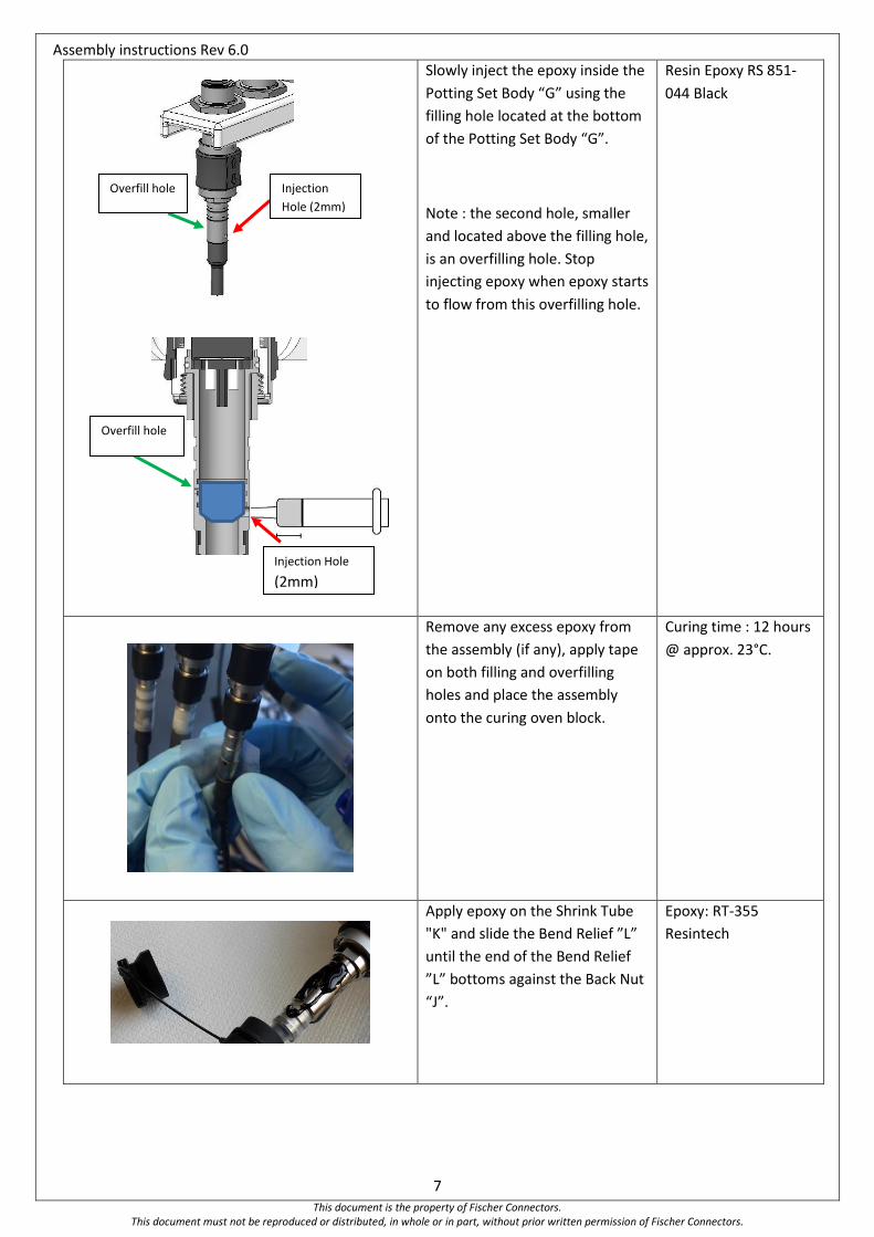
Slowly inject the epoxy inside the
Potting Set Body “G” using the
filling hole located at the bottom
of the Potting Set Body “G”.
Note : the second hole, smaller
and located above the filling hole,
is an overfilling hole. Stop
injecting epoxy when epoxy starts
to flow from this overfilling hole.
Resin Epoxy RS 851-
044 Black
Remove any excess epoxy from
the assembly (if any), apply tape
on both filling and overfilling
holes and place the assembly
onto the curing oven block.
Curing time : 12 hours
@ approx. 23°C.
Apply epoxy on the Shrink Tube
"K" and slide the Bend Relief ”L”
until the end of the Bend Relief
”L” bottoms against the Back Nut
“J”.
Epoxy: RT-355
Resintech
Injection Hole
(2mm)
Overfill hole
(1mm)
Injection
Hole (2mm)
Overfill hole
Assembly instructions Rev 6.0
8 This document is the property of Fischer Connectors.
This document must not be reproduced or distributed, in whole or in part, without prior written permission of Fischer Connectors.
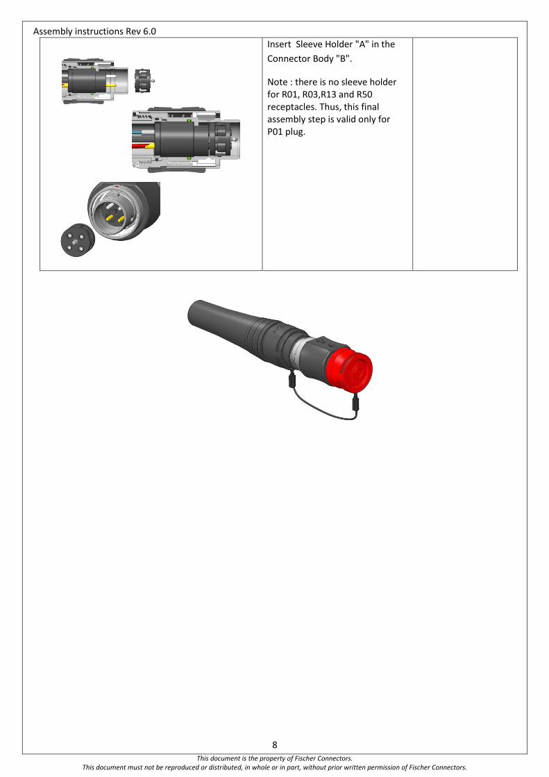
Insert Sleeve Holder "A" in the
Connector Body "B".
Note : there is no sleeve holder for R01, R03,R13 and R50 receptacles. Thus, this final assembly step is valid only for P01 plug.
Assembly instructions Rev 6.0
9 This document is the property of Fischer Connectors.
This document must not be reproduced or distributed, in whole or in part, without prior written permission of Fischer Connectors.
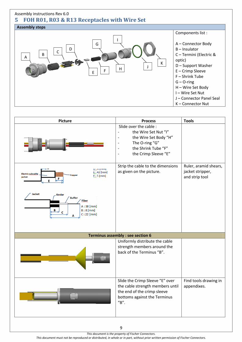
5 FOH R01, R03 & R13 Receptacles with Wire Set Assembly steps
Components list : A – Connector Body B – Insulator C – Termini (Electric & optic) D – Support Washer E – Crimp Sleeve F – Shrink Tube G – O-ring H – Wire Set Body I – Wire Set Nut J – Connector Panel Seal K – Connector Nut
Picture Process Tools
Slide over the cable : - the Wire Set Nut “I” - the Wire Set Body “H” - The O-ring “G” - the Shrink Tube “F” - the Crimp Sleeve “E”
Strip the cable to the dimensions as given on the picture.
Ruler, aramid shears, jacket stripper, and strip tool
Terminus assembly : see section 6
Uniformly distribute the cable strength members around the back of the Terminus “B”.
Slide the Crimp Sleeve “E” over the cable strength members until the end of the crimp sleeve bottoms against the Terminus “B”.
Find tools drawing in appendixes.
A B
C D
E F H
I G
J K
Assembly instructions Rev 6.0
10 This document is the property of Fischer Connectors.
This document must not be reproduced or distributed, in whole or in part, without prior written permission of Fischer Connectors.
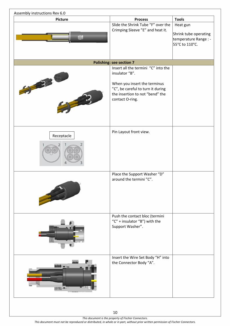
Picture Process Tools
Slide the Shrink Tube “F” over the Crimping Sleeve ”E” and heat it.
Heat gun
Shrink tube operating temperature Range : -55°C to 110°C.
Polishing: see section 7
Insert all the termini “C” into the insulator “B”. When you insert the terminus ”C”, be careful to turn it during the insertion to not “bend” the contact O-ring.
Pin Layout front view.
Place the Support Washer “D” around the termini ”C”.
Push the contact bloc (termini “C” + insulator “B”) with the Support Washer”.
Insert the Wire Set Body “H” into the Connector Body “A”.
Receptacle
Assembly instructions Rev 6.0
11 This document is the property of Fischer Connectors.
This document must not be reproduced or distributed, in whole or in part, without prior written permission of Fischer Connectors.
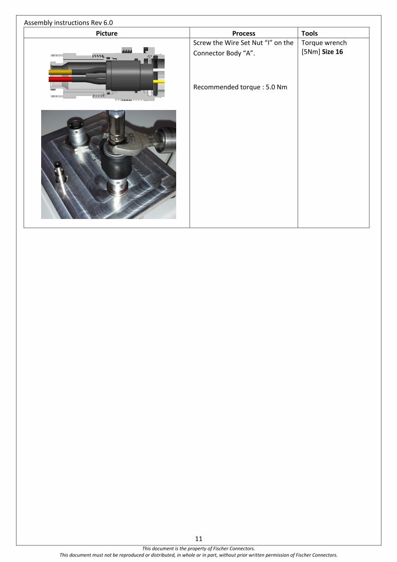
Picture Process Tools
Screw the Wire Set Nut “I” on the
Connector Body “A”.
Recommended torque : 5.0 Nm
Torque wrench [5Nm] Size 16

Assembly instructions Rev 6.0
12 This document is the property of Fischer Connectors.
This document must not be reproduced or distributed, in whole or in part, without prior written permission of Fischer Connectors.
6 Terminus assembly Assembly steps
Components list : A – Housing O-Ring B – Termini Housing C – Ferrule O-Ring D – Ferrule E – Spring F – Termini Closure
Picture Process Tools
Slide over the cable : - the Termini Closure “F” - the Spring “E”
Prepare the cable according to stripping dimension from the relevant section.
Insert epoxy into the Ferrule “D” until a little drop appears at the ferrule end. Carefully insert the fiber into the back of the Ferrule “D and make sure the buffer slides inside the ferrule the buffer bottoms on the ceramic.
Extended Working Life, 2-Part Epoxy, 2.5 Gram Packet Frs : FIBER OPTIC CENTER Ref : ET383ND-2.5G
Remove any excess epoxy from the assembly
Cure the epoxy 120 +10/- 20[°C] during 20min.
Cleave fiber Scribe Tool
A
B C
D
E F
Assembly instructions Rev 6.0
13 This document is the property of Fischer Connectors.
This document must not be reproduced or distributed, in whole or in part, without prior written permission of Fischer Connectors.
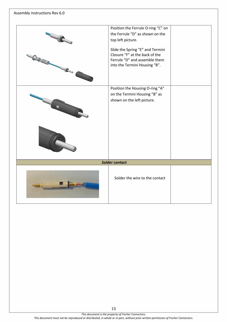
Position the Ferrule O-ring “C” on
the Ferrule “D” as shown on the
top left picture.
Slide the Spring “E” and Termini Closure “F” at the back of the Ferrule “D” and assemble them into the Termini Housing “B”.
Position the Housing O-ring “A”
on the Termini Housing “B” as
shown on the left picture.
Solder contact
Solder the wire to the contact
Assembly instructions Rev 6.0
14 This document is the property of Fischer Connectors.
This document must not be reproduced or distributed, in whole or in part, without prior written permission of Fischer Connectors.
7 Polishing It is recommended polishing the fiber using a polishing machine.
Polish the fiber according to the machine manufacturer’s instructions.
Picture Process Tools
PC termini
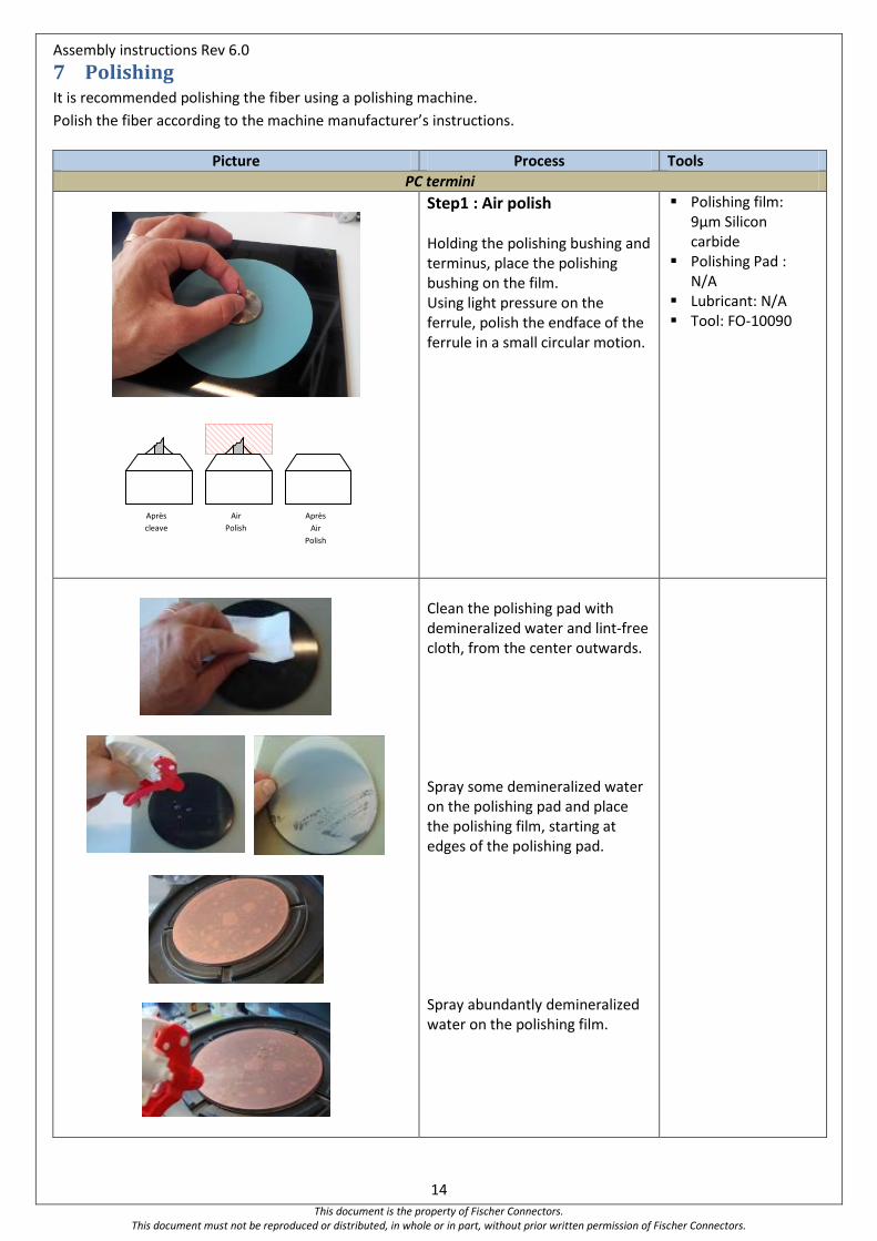
Step1 : Air polish
Holding the polishing bushing and terminus, place the polishing bushing on the film. Using light pressure on the ferrule, polish the endface of the ferrule in a small circular motion.
Polishing film: 9µm Silicon carbide
Polishing Pad : N/A
Lubricant: N/A Tool: FO-10090
Clean the polishing pad with demineralized water and lint-free cloth, from the center outwards. Spray some demineralized water on the polishing pad and place the polishing film, starting at edges of the polishing pad. Spray abundantly demineralized water on the polishing film.
Après
cleave
Air
Polish
Après
Air
Polish
Assembly instructions Rev 6.0
15 This document is the property of Fischer Connectors.
This document must not be reproduced or distributed, in whole or in part, without prior written permission of Fischer Connectors.
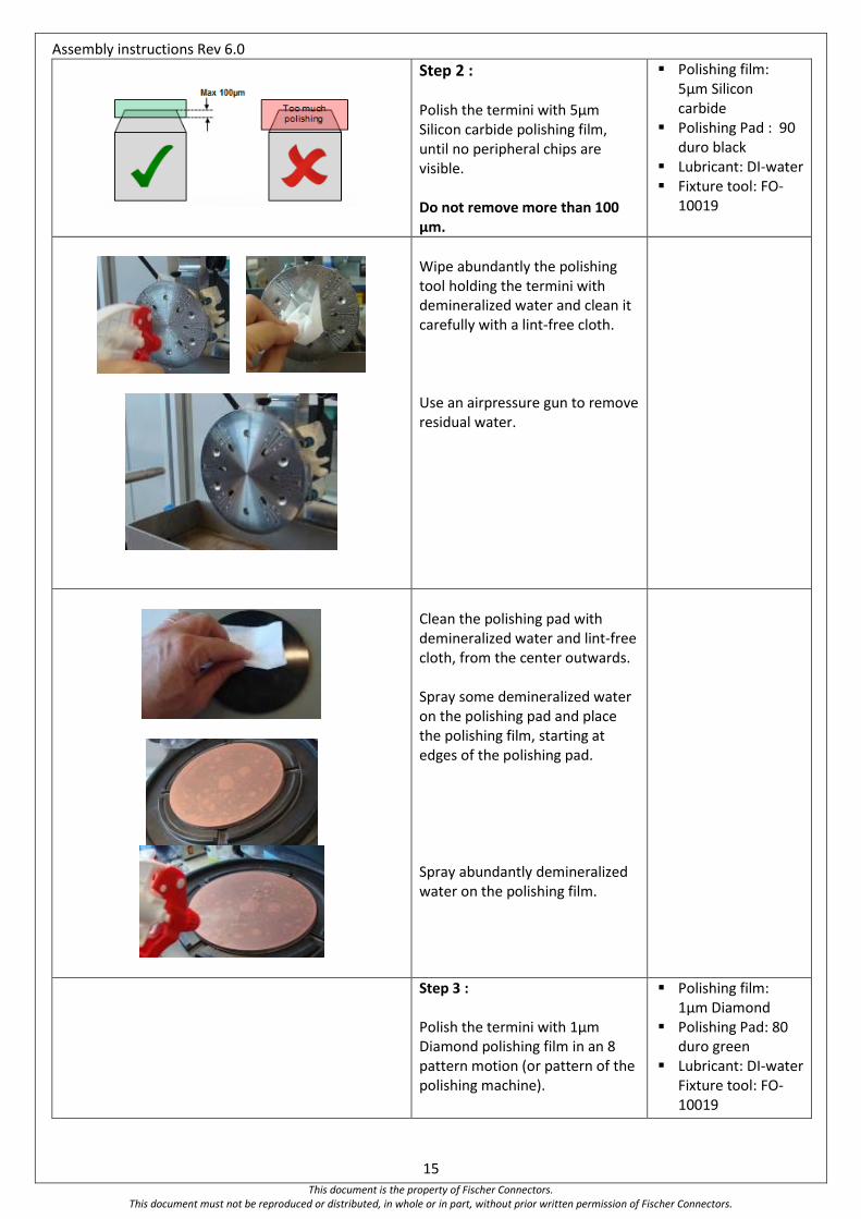
Step 2 : Polish the termini with 5µm Silicon carbide polishing film, until no peripheral chips are visible. Do not remove more than 100 µm.
Polishing film: 5µm Silicon carbide
Polishing Pad : 90 duro black
Lubricant: DI-water Fixture tool: FO-
10019
Wipe abundantly the polishing tool holding the termini with demineralized water and clean it carefully with a lint-free cloth. Use an airpressure gun to remove residual water.
Clean the polishing pad with demineralized water and lint-free cloth, from the center outwards. Spray some demineralized water on the polishing pad and place the polishing film, starting at edges of the polishing pad. Spray abundantly demineralized water on the polishing film.
Step 3 : Polish the termini with 1µm Diamond polishing film in an 8 pattern motion (or pattern of the polishing machine).
Polishing film: 1µm Diamond
Polishing Pad: 80 duro green
Lubricant: DI-water Fixture tool: FO-10019
Assembly instructions Rev 6.0
16 This document is the property of Fischer Connectors.
This document must not be reproduced or distributed, in whole or in part, without prior written permission of Fischer Connectors.
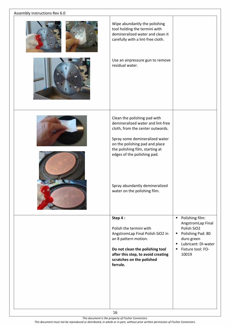
Wipe abundantly the polishing tool holding the termini with demineralized water and clean it carefully with a lint-free cloth. Use an airpressure gun to remove residual water.
Clean the polishing pad with demineralized water and lint-free cloth, from the center outwards. Spray some demineralized water on the polishing pad and place the polishing film, starting at edges of the polishing pad. Spray abundantly demineralized water on the polishing film.
Step 4 : Polish the termini with AngstromLap Final Polish SiO2 in an 8 pattern motion. Do not clean the polishing tool after this step, to avoid creating scratches on the polished ferrule.
Polishing film: AngstromLap Final Polish SiO2
Polishing Pad: 80 duro green
Lubricant: DI-water Fixture tool: FO-
10019
Assembly instructions Rev 6.0
17 This document is the property of Fischer Connectors.
This document must not be reproduced or distributed, in whole or in part, without prior written permission of Fischer Connectors.
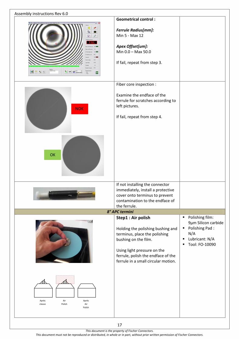
Geometrical control : Ferrule Radius[mm]: Min 5 - Max 12 Apex Offset[um]: Min 0.0 – Max 50.0 If fail, repeat from step 3.
Fiber core inspection : Examine the endface of the ferrule for scratches according to left pictures. If fail, repeat from step 4.
If not installing the connector immediately, install a protective cover onto terminus to prevent contamination to the endface of the ferrule.
8° APC termini
Step1 : Air polish
Holding the polishing bushing and terminus, place the polishing bushing on the film. Using light pressure on the ferrule, polish the endface of the ferrule in a small circular motion.
Polishing film: 9µm Silicon carbide
Polishing Pad : N/A
Lubricant: N/A Tool: FO-10090
NOK
OK
Après
cleave
Air
Polish
Après
Air
Polish
Assembly instructions Rev 6.0
18 This document is the property of Fischer Connectors.
This document must not be reproduced or distributed, in whole or in part, without prior written permission of Fischer Connectors.
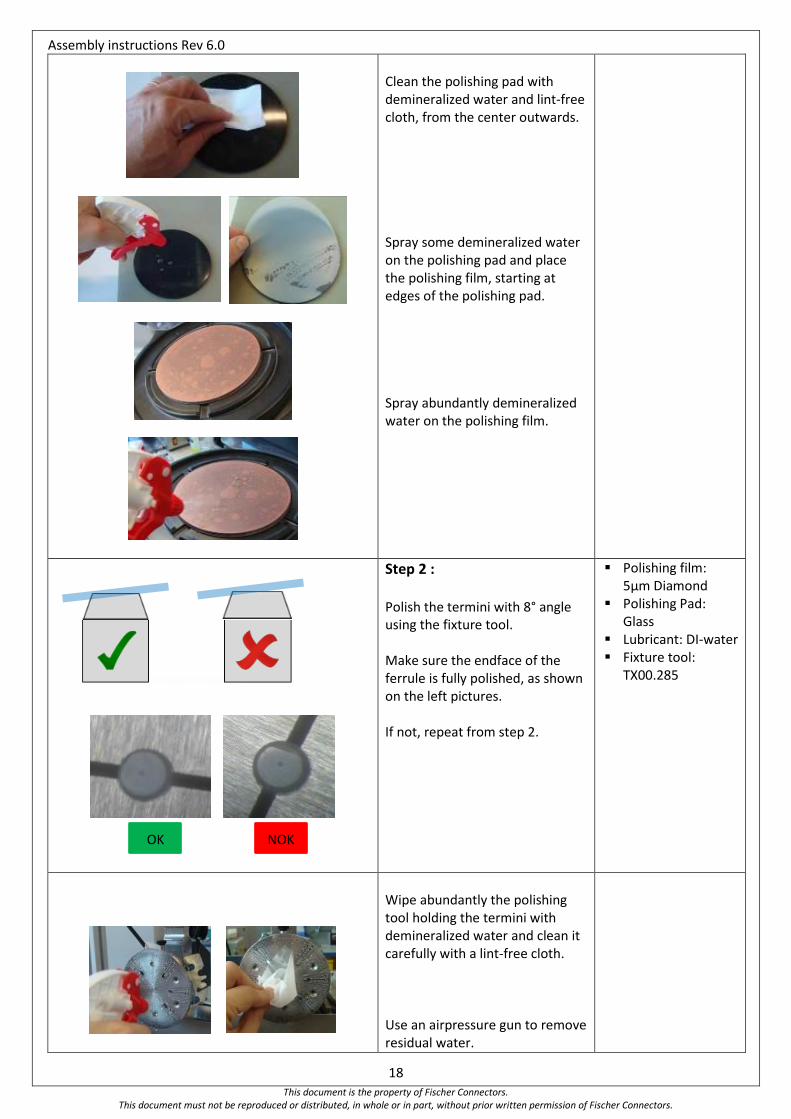
Clean the polishing pad with demineralized water and lint-free cloth, from the center outwards. Spray some demineralized water on the polishing pad and place the polishing film, starting at edges of the polishing pad. Spray abundantly demineralized water on the polishing film.
Step 2 : Polish the termini with 8° angle using the fixture tool. Make sure the endface of the ferrule is fully polished, as shown on the left pictures. If not, repeat from step 2.
Polishing film: 5µm Diamond
Polishing Pad: Glass
Lubricant: DI-water Fixture tool:
TX00.285
Wipe abundantly the polishing tool holding the termini with demineralized water and clean it carefully with a lint-free cloth. Use an airpressure gun to remove residual water.
NOK OK
Assembly instructions Rev 6.0
19 This document is the property of Fischer Connectors.
This document must not be reproduced or distributed, in whole or in part, without prior written permission of Fischer Connectors.
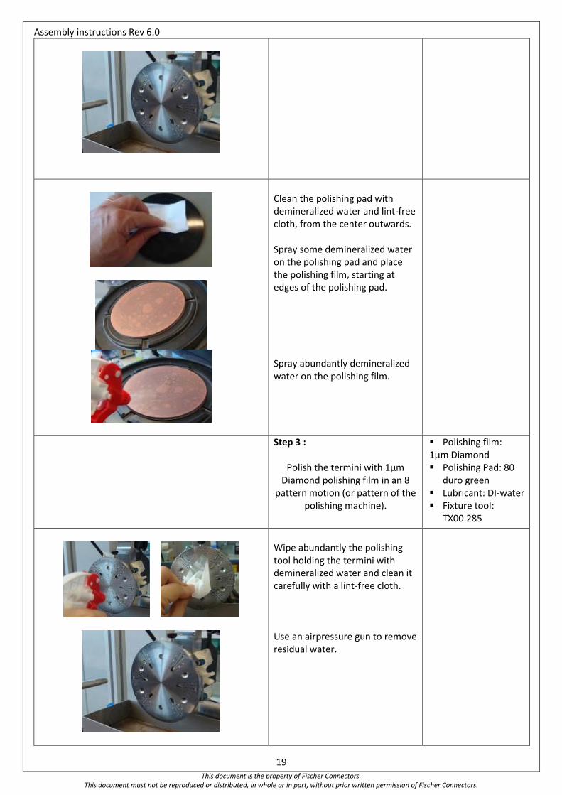
Clean the polishing pad with demineralized water and lint-free cloth, from the center outwards. Spray some demineralized water on the polishing pad and place the polishing film, starting at edges of the polishing pad. Spray abundantly demineralized water on the polishing film.
Step 3 :
Polish the termini with 1µm Diamond polishing film in an 8
pattern motion (or pattern of the polishing machine).
Polishing film: 1µm Diamond Polishing Pad: 80
duro green Lubricant: DI-water Fixture tool:
TX00.285
Wipe abundantly the polishing tool holding the termini with demineralized water and clean it carefully with a lint-free cloth. Use an airpressure gun to remove residual water.
Assembly instructions Rev 6.0
20 This document is the property of Fischer Connectors.
This document must not be reproduced or distributed, in whole or in part, without prior written permission of Fischer Connectors.
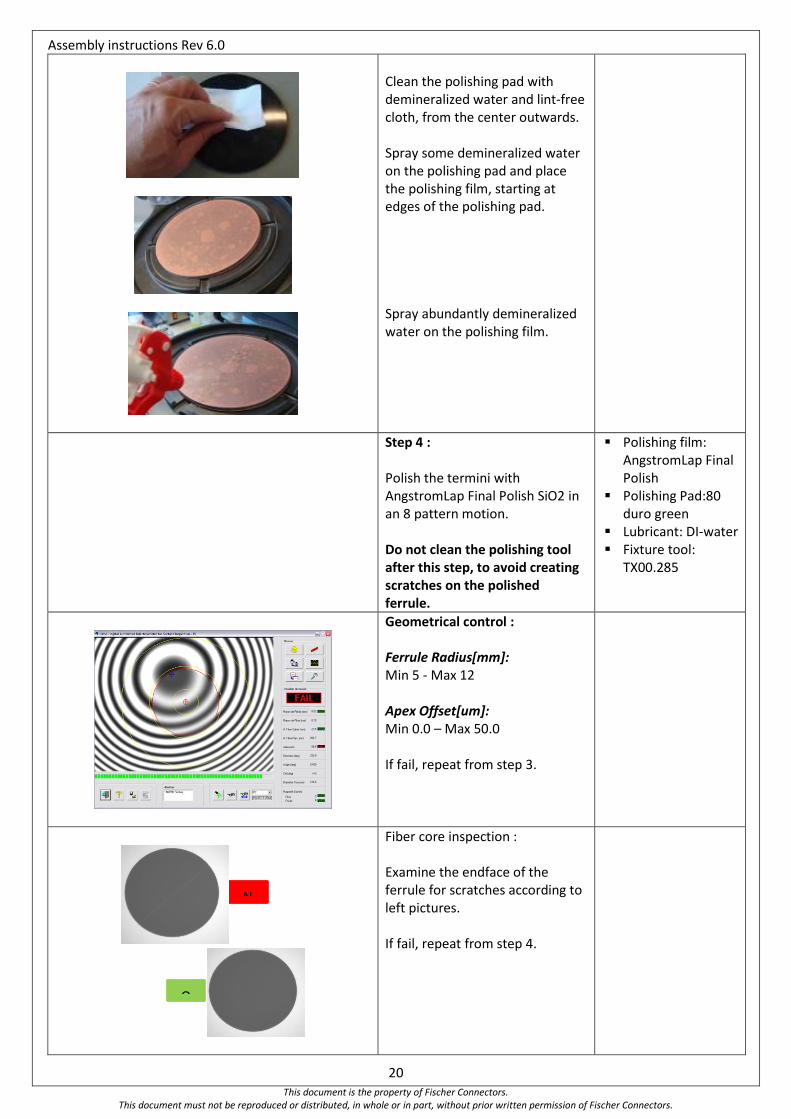
Clean the polishing pad with demineralized water and lint-free cloth, from the center outwards. Spray some demineralized water on the polishing pad and place the polishing film, starting at edges of the polishing pad. Spray abundantly demineralized water on the polishing film.
Step 4 : Polish the termini with AngstromLap Final Polish SiO2 in an 8 pattern motion. Do not clean the polishing tool after this step, to avoid creating scratches on the polished ferrule.
Polishing film: AngstromLap Final Polish
Polishing Pad:80 duro green
Lubricant: DI-water Fixture tool:
TX00.285
Geometrical control : Ferrule Radius[mm]: Min 5 - Max 12 Apex Offset[um]: Min 0.0 – Max 50.0 If fail, repeat from step 3.
Fiber core inspection : Examine the endface of the ferrule for scratches according to left pictures. If fail, repeat from step 4.
N
O

Assembly instructions Rev 6.0
21 This document is the property of Fischer Connectors.
This document must not be reproduced or distributed, in whole or in part, without prior written permission of Fischer Connectors.
If not installing the connector immediately, install a protective cover onto terminus to prevent contamination to the endface of the ferrule.
Assembly instructions Rev 6.0
22 This document is the property of Fischer Connectors.
This document must not be reproduced or distributed, in whole or in part, without prior written permission of Fischer Connectors.
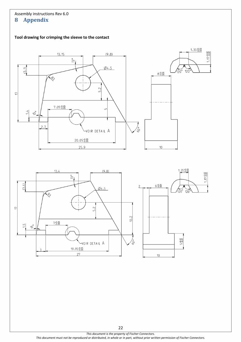
8 Appendix
Tool drawing for crimping the sleeve to the contact
Assembly instructions Rev 6.0
23 This document is the property of Fischer Connectors.
This document must not be reproduced or distributed, in whole or in part, without prior written permission of Fischer Connectors.
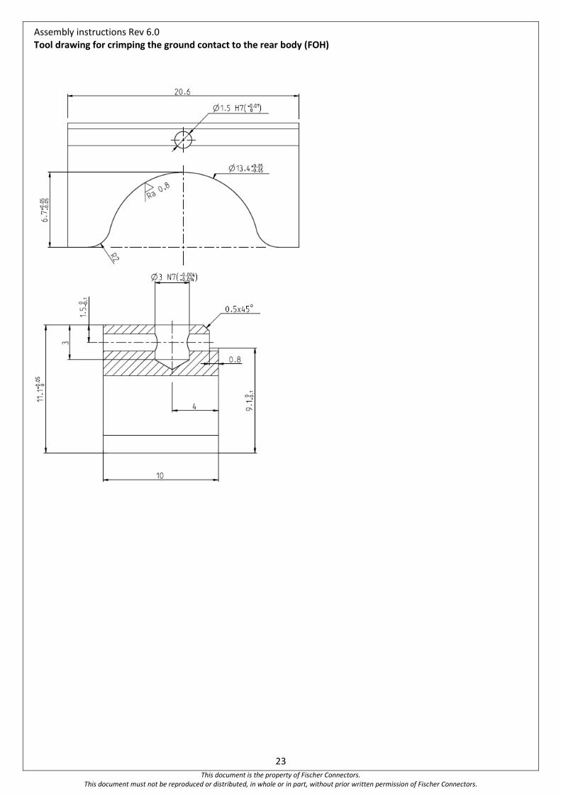
Tool drawing for crimping the ground contact to the rear body (FOH)