Assembly, Installation and Interfaces Steve Virostek Lawrence Berkeley National Lab RFCC Module...
33
Assembly, Installation and Interfaces Steve Virostek Lawrence Berkeley National Lab RFCC Module Design Review October 21, 2008
-
Upload
ashlyn-wilkinson -
Category
Documents
-
view
215 -
download
0
Transcript of Assembly, Installation and Interfaces Steve Virostek Lawrence Berkeley National Lab RFCC Module...
Assembly, Installation and Interfaces
Steve VirostekLawrence Berkeley National Lab
RFCC Module Design Review
October 21, 2008
MICE RFCC Module Design Review – Assembly, Installation and Interfaces
Page 2Steve Virostek - Lawrence Berkeley National Lab - October 21, 2008
Topic Summary
•Packaging and delivery to RAL
•Moving into MICE hall
•Module re-assembly in MICE hall
•Module installation interfaces•End flanges and seals•Base mounting•RF coupler connections
•Utility requirements
•Instrumentation & control
MICE RFCC Module Design Review – Assembly, Installation and Interfaces
Page 3Steve Virostek - Lawrence Berkeley National Lab - October 21, 2008
Module Shipping Configuration
•Cavities, couplers, coolers & pumps removed•Coupling coil shipped warm
•Vacuum vessel/magnet axis vertical during shipping•Concerns about shipping loads on coupling coil•Special shipping fixture will be required
•Cavities, couplers packaged to prevent damage•RF, Be windows left in place w/appropriate protection
•Vacuum vessel, cavities and couplers will be blanked off and backfilled with N2
MICE RFCC Module Design Review – Assembly, Installation and Interfaces
Page 4Steve Virostek - Lawrence Berkeley National Lab - October 21, 2008
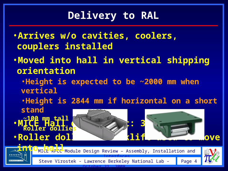
Delivery to RAL
•Arrives w/o cavities, coolers, couplers installed
•Moved into hall in vertical shipping orientation•Height is expected to be ~2000 mm when vertical•Height is 2844 mm if horizontal on a short stand
•MICE Hall door height: 3360 mm
•Roller dollies w/forklift used to move into hall
~100 mm tall
Roller dollies
MICE RFCC Module Design Review – Assembly, Installation and Interfaces
Page 5Steve Virostek - Lawrence Berkeley National Lab - October 21, 2008
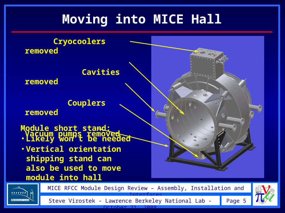
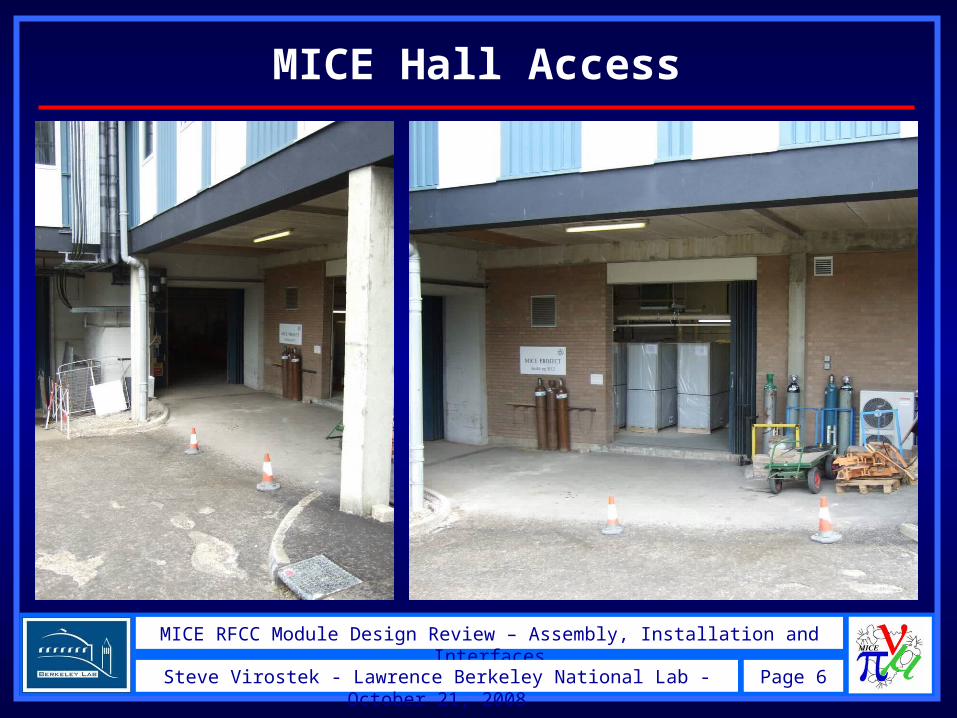
Moving into MICE Hall
Module short stand:•Likely won’t be needed•Vertical orientation shipping stand can also be used to move module into hall
Cryocoolers removed
Cavities removed
Couplers removed
Vacuum pumps removed
MICE RFCC Module Design Review – Assembly, Installation and Interfaces
Page 6Steve Virostek - Lawrence Berkeley National Lab - October 21, 2008
MICE Hall Access
MICE RFCC Module Design Review – Assembly, Installation and Interfaces
Page 7Steve Virostek - Lawrence Berkeley National Lab - October 21, 2008
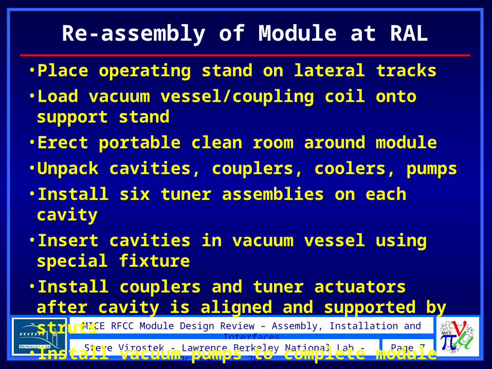
•Place operating stand on lateral tracks•Load vacuum vessel/coupling coil onto support stand
•Erect portable clean room around module•Unpack cavities, couplers, coolers, pumps•Install six tuner assemblies on each cavity•Insert cavities in vacuum vessel using special fixture
•Install couplers and tuner actuators after cavity is aligned and supported by struts
•Install vacuum pumps to complete module•Perform final alignment before translation
Re-assembly of Module at RAL
MICE RFCC Module Design Review – Assembly, Installation and Interfaces
Page 8Steve Virostek - Lawrence Berkeley National Lab - October 21, 2008
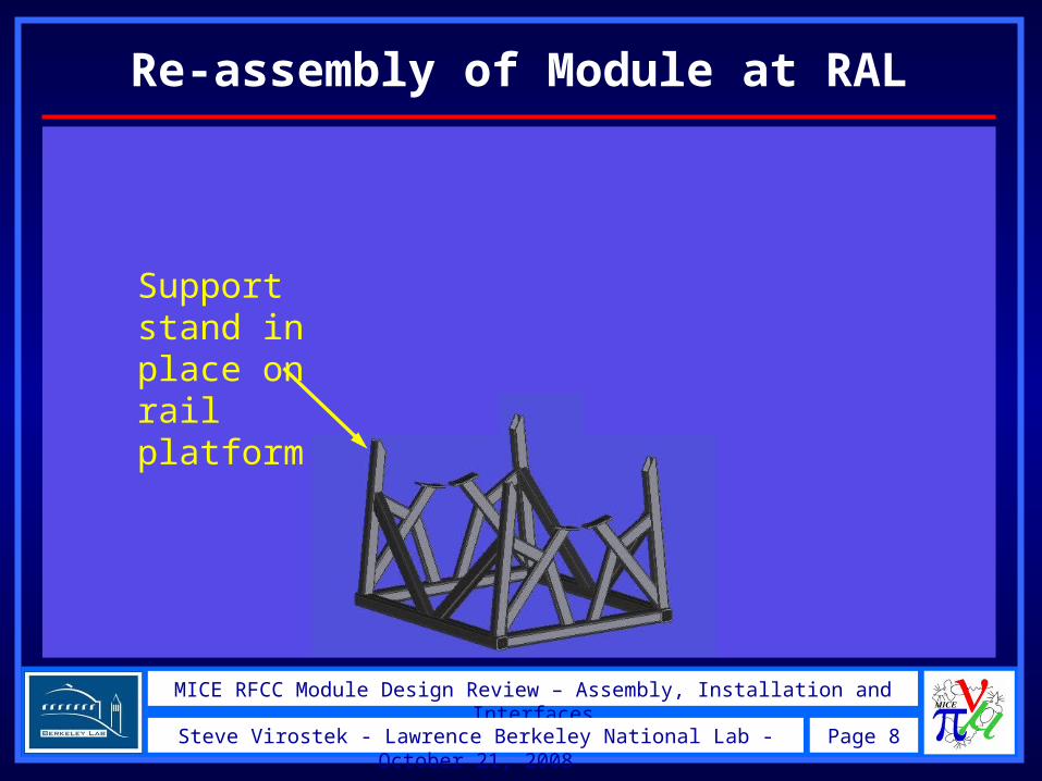
Re-assembly of Module at RAL
Support stand in place on rail platform
MICE RFCC Module Design Review – Assembly, Installation and Interfaces
Page 9Steve Virostek - Lawrence Berkeley National Lab - October 21, 2008
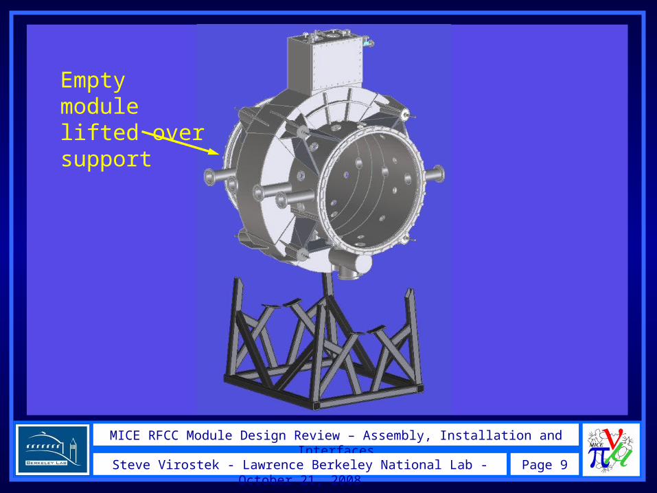
Empty module lifted over support
MICE RFCC Module Design Review – Assembly, Installation and Interfaces
Page 10Steve Virostek - Lawrence Berkeley National Lab - October 21, 2008
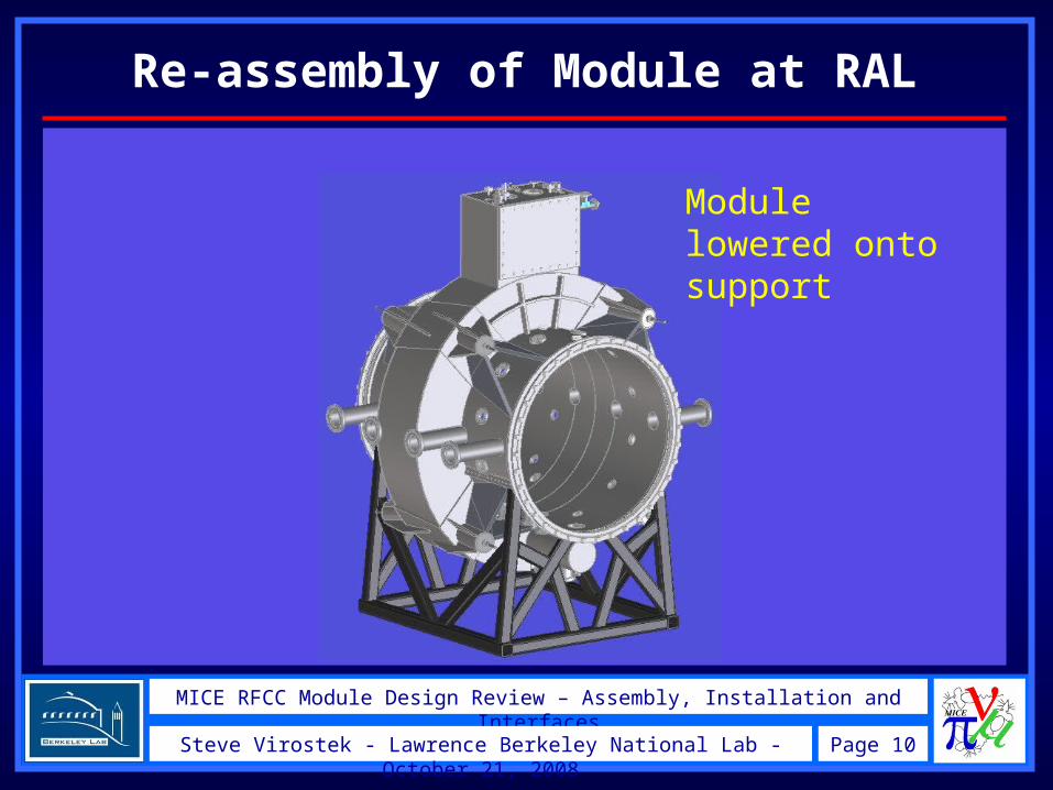
Re-assembly of Module at RAL
Module lowered onto support
MICE RFCC Module Design Review – Assembly, Installation and Interfaces
Page 11Steve Virostek - Lawrence Berkeley National Lab - October 21, 2008
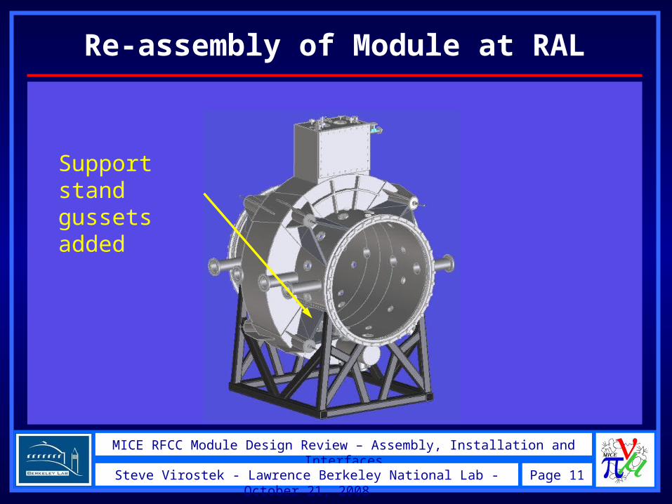
Re-assembly of Module at RAL
Support stand gussets added
MICE RFCC Module Design Review – Assembly, Installation and Interfaces
Page 12Steve Virostek - Lawrence Berkeley National Lab - October 21, 2008
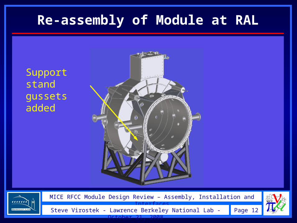
Re-assembly of Module at RAL
Support stand gussets added
MICE RFCC Module Design Review – Assembly, Installation and Interfaces
Page 13Steve Virostek - Lawrence Berkeley National Lab - October 21, 2008
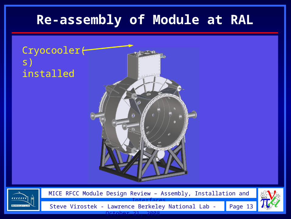
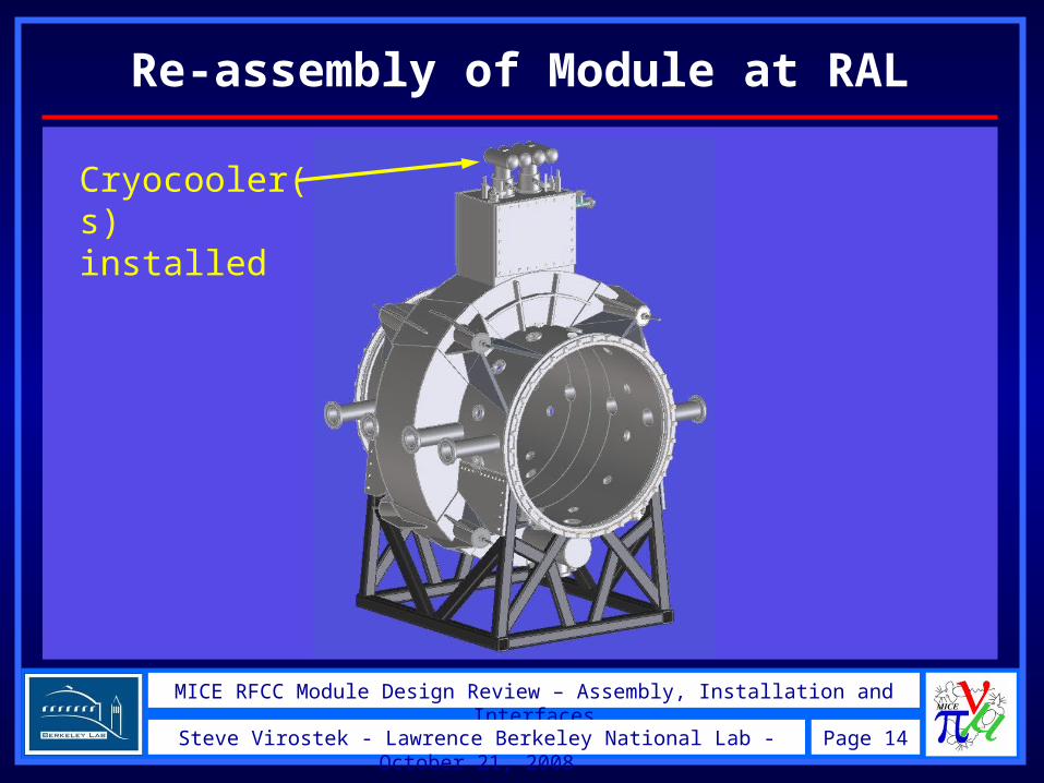
Re-assembly of Module at RAL
Cryocooler(s) installed
MICE RFCC Module Design Review – Assembly, Installation and Interfaces
Page 14Steve Virostek - Lawrence Berkeley National Lab - October 21, 2008
Re-assembly of Module at RAL
Cryocooler(s) installed
MICE RFCC Module Design Review – Assembly, Installation and Interfaces
Page 15Steve Virostek - Lawrence Berkeley National Lab - October 21, 2008
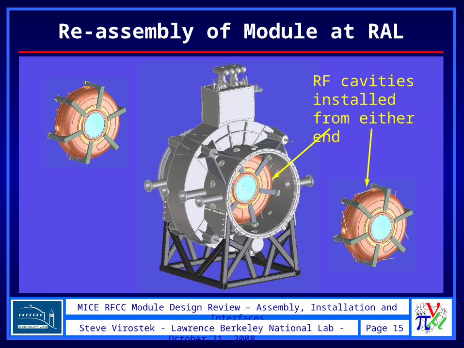
Re-assembly of Module at RAL
RF cavities installed from either end
MICE RFCC Module Design Review – Assembly, Installation and Interfaces
Page 16Steve Virostek - Lawrence Berkeley National Lab - October 21, 2008
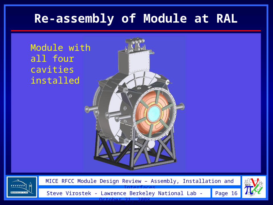
Re-assembly of Module at RAL
Module with all four cavities installed

MICE RFCC Module Design Review – Assembly, Installation and Interfaces
Page 17Steve Virostek - Lawrence Berkeley National Lab - October 21, 2008
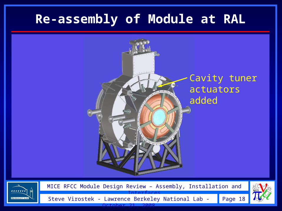
Re-assembly of Module at RAL
Cavity tuner actuators added
MICE RFCC Module Design Review – Assembly, Installation and Interfaces
Page 18Steve Virostek - Lawrence Berkeley National Lab - October 21, 2008
Re-assembly of Module at RAL
Cavity tuner actuators added
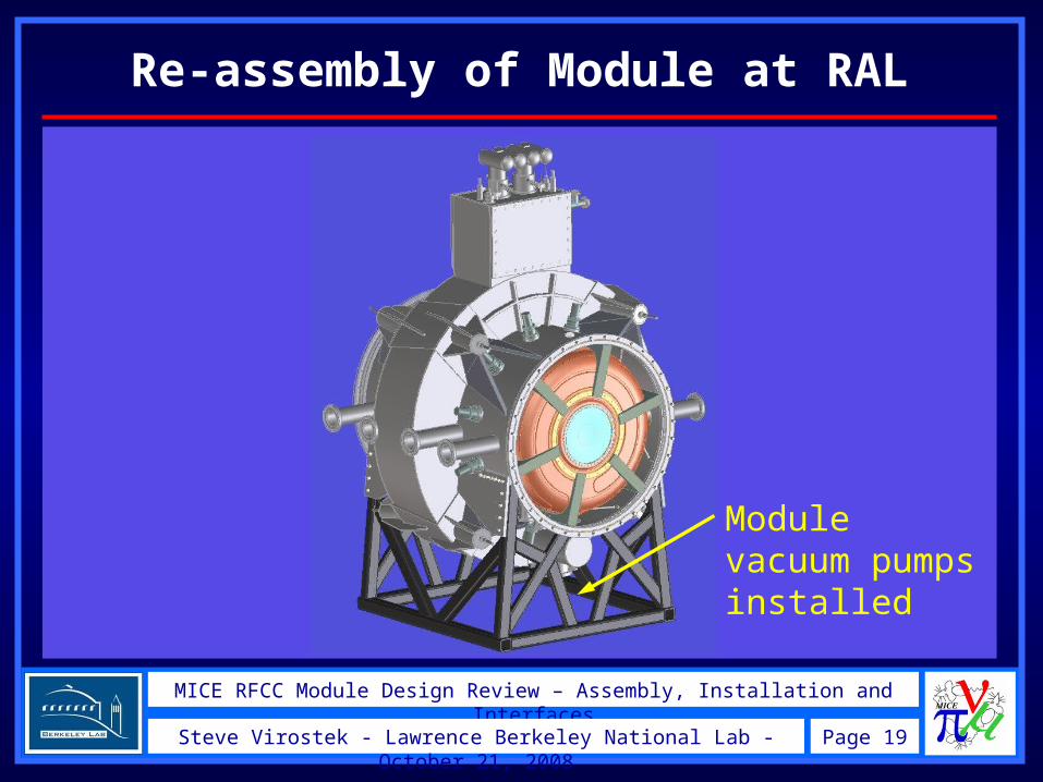
MICE RFCC Module Design Review – Assembly, Installation and Interfaces
Page 19Steve Virostek - Lawrence Berkeley National Lab - October 21, 2008
Re-assembly of Module at RAL
Module vacuum pumps installed
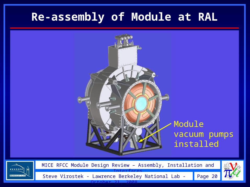
MICE RFCC Module Design Review – Assembly, Installation and Interfaces
Page 20Steve Virostek - Lawrence Berkeley National Lab - October 21, 2008
Re-assembly of Module at RAL
Module vacuum pumps installed
MICE RFCC Module Design Review – Assembly, Installation and Interfaces
Page 21Steve Virostek - Lawrence Berkeley National Lab - October 21, 2008
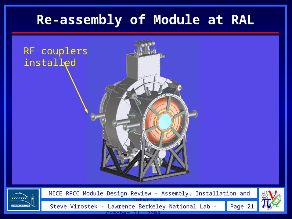
Re-assembly of Module at RAL
RF couplers installed

MICE RFCC Module Design Review – Assembly, Installation and Interfaces
Page 22Steve Virostek - Lawrence Berkeley National Lab - October 21, 2008
Re-assembly of Module at RAL
RF couplers installed
MICE RFCC Module Design Review – Assembly, Installation and Interfaces
Page 23Steve Virostek - Lawrence Berkeley National Lab - October 21, 2008
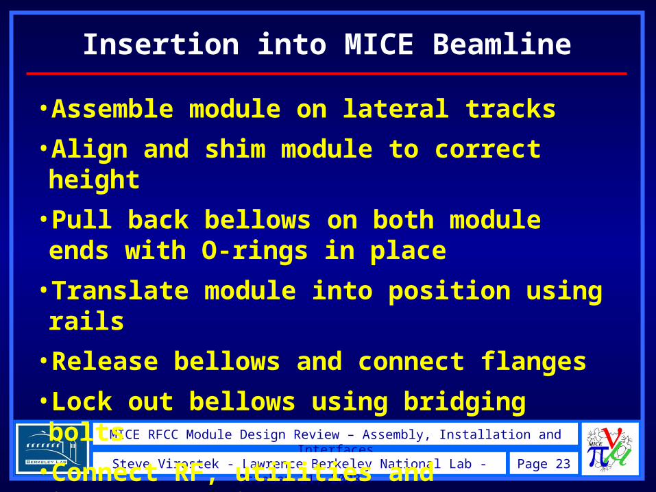
Insertion into MICE Beamline
•Assemble module on lateral tracks
•Align and shim module to correct height
•Pull back bellows on both module ends with O-rings in place
•Translate module into position using rails
•Release bellows and connect flanges
•Lock out bellows using bridging bolts
•Connect RF, utilities and instrumentation
MICE RFCC Module Design Review – Assembly, Installation and Interfaces
Page 24Steve Virostek - Lawrence Berkeley National Lab - October 21, 2008
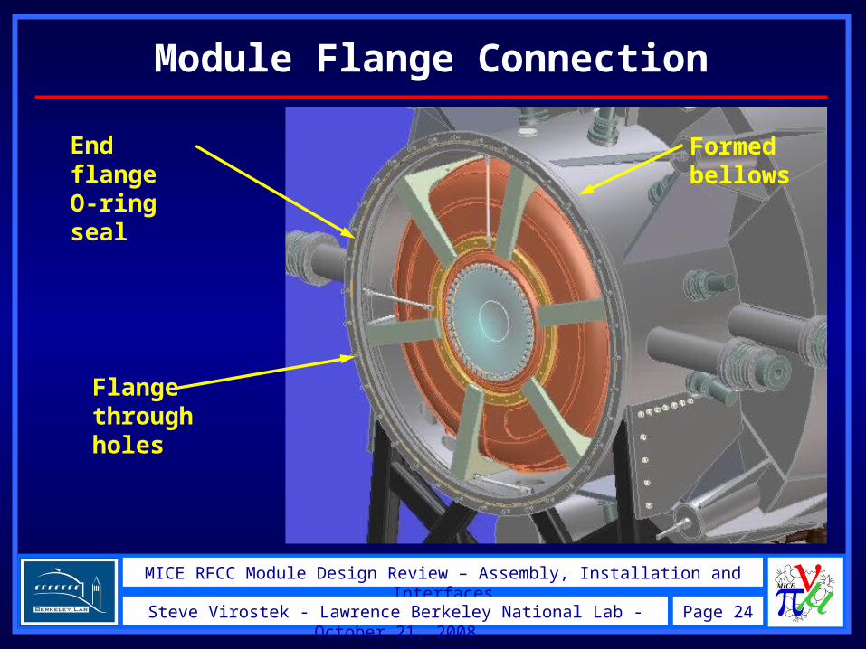
Module Flange Connection
End flange O-ring seal
Formed bellows
Flange through holes
MICE RFCC Module Design Review – Assembly, Installation and Interfaces
Page 25Steve Virostek - Lawrence Berkeley National Lab - October 21, 2008
End Flanges and Seals
•RFCC flanges mate with AFC module flanges
•AFC flanges have no O-ring grooves or bellows
•RFCC module flanges have bellows and O-ring grooves at both ends
•Bellows are spec’d for >1 cm of total travel
•Module relative alignment is driven by clearance in flange holes
•Bellows are locked out after installation to allow transmission of forces between modules
MICE RFCC Module Design Review – Assembly, Installation and Interfaces
Page 26Steve Virostek - Lawrence Berkeley National Lab - October 21, 2008
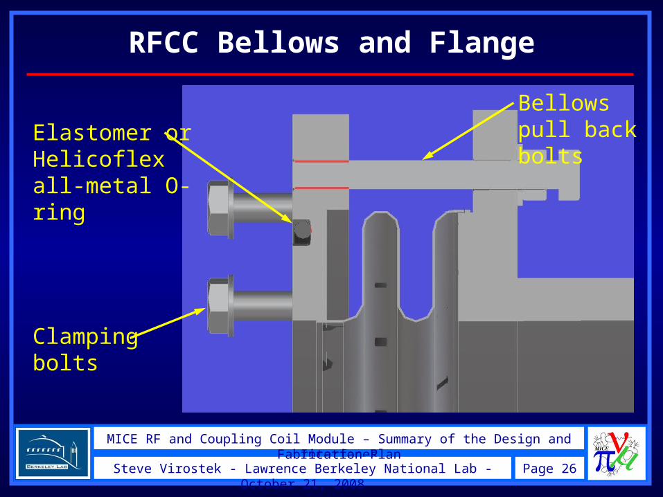
RFCC Bellows and Flange
MICE RF and Coupling Coil Module – Summary of the Design and Fabrication Plan
Elastomer or Helicoflex all-metal O-ring
Clamping bolts
Bellows pull back bolts
MICE RFCC Module Design Review – Assembly, Installation and Interfaces
Page 27Steve Virostek - Lawrence Berkeley National Lab - October 21, 2008
MICE RF and Coupling Coil Module – Summary of the Design and Fabrication Plan
Module Joint Sealing Issues
•MICE module joints likely to need relatively frequent disassembly (reconfiguring, maintenance, repair)
•Elastomer O-rings provide the most reliable and cost effective (inexpensive and re-useable) solution
•O-rings are acceptable for use in MICE environment
•But, MICE should demonstrate future machine technology including the use of radiation hard seals
•The RFCC flange groove is designed to accept an all-metal Helicoflex seal for demonstration purposes
MICE RFCC Module Design Review – Assembly, Installation and Interfaces
Page 28Steve Virostek - Lawrence Berkeley National Lab - October 21, 2008
Module Base Mounting
•RFCC module base connection to rails similar to that used on the Spectrometer Solenoid
•Six mounting plates are welded to the base of the module support stand
•Location of the mounting plates will be included in an interface document being developed
•Coupling coil magnetic loads are carried to the floor through the vacuum vessel/support stand/base mounting plates
MICE RFCC Module Design Review – Assembly, Installation and Interfaces
Page 29Steve Virostek - Lawrence Berkeley National Lab - October 21, 2008
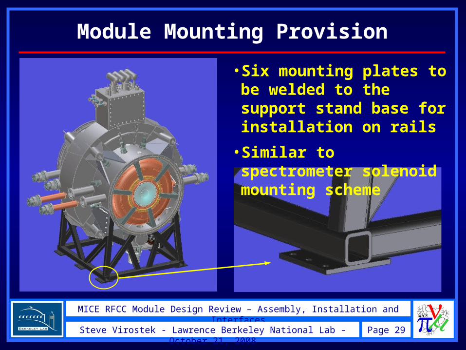
Module Mounting Provision
•Six mounting plates to be welded to the support stand base for installation on rails
•Similar to spectrometer solenoid mounting scheme
MICE RFCC Module Design Review – Assembly, Installation and Interfaces
Page 30Steve Virostek - Lawrence Berkeley National Lab - October 21, 2008
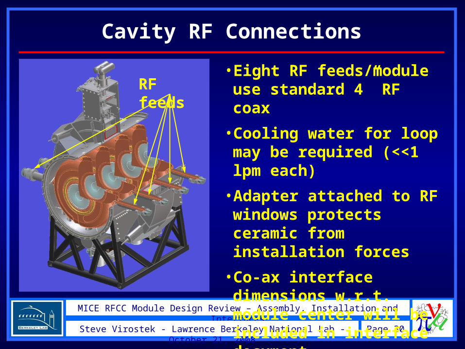
Cavity RF Connections
•Eight RF feeds/module use standard 4” RF coax
•Cooling water for loop may be required (<<1 lpm each)
•Adapter attached to RF windows protects ceramic from installation forces
•Co-ax interface dimensions w.r.t. module center will be included in interface document
RF feeds
MICE RFCC Module Design Review – Assembly, Installation and Interfaces
Page 31Steve Virostek - Lawrence Berkeley National Lab - October 21, 2008
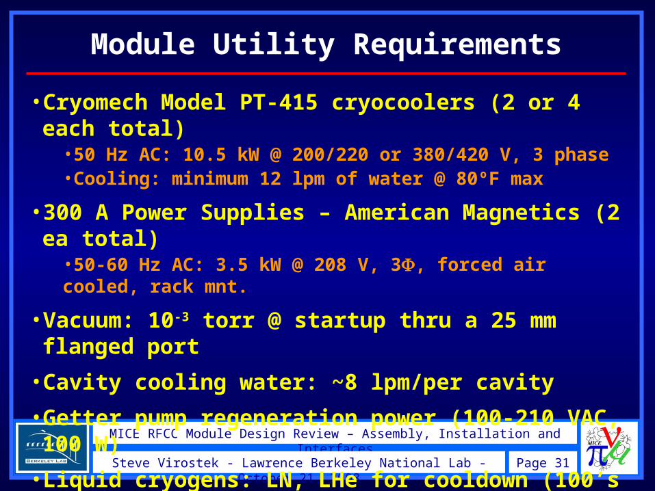
Module Utility Requirements
•Cryomech Model PT-415 cryocoolers (2 or 4 each total)
•50 Hz AC: 10.5 kW @ 200/220 or 380/420 V, 3 phase•Cooling: minimum 12 lpm of water @ 80ºF max
•300 A Power Supplies – American Magnetics (2 ea total)
•50-60 Hz AC: 3.5 kW @ 208 V, 3, forced air cooled, rack mnt.
•Vacuum: 10-3 torr @ startup thru a 25 mm flanged port
•Cavity cooling water: ~8 lpm/per cavity
•Getter pump regeneration power (100-210 VAC, 100 W)
•Liquid cryogens: LN, LHe for cooldown (100’s of liters)
•Pressurized N2: up to 300 psi for tuner actuators
MICE RFCC Module Design Review – Assembly, Installation and Interfaces
Page 32Steve Virostek - Lawrence Berkeley National Lab - October 21, 2008
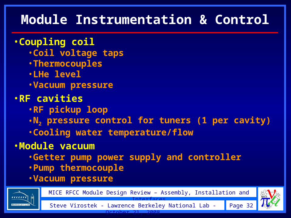
Module Instrumentation & Control
•Coupling coil•Coil voltage taps•Thermocouples•LHe level•Vacuum pressure
•RF cavities•RF pickup loop•N2 pressure control for tuners (1 per cavity)•Cooling water temperature/flow
•Module vacuum•Getter pump power supply and controller•Pump thermocouple•Vacuum pressure
MICE RFCC Module Design Review – Assembly, Installation and Interfaces
Page 33Steve Virostek - Lawrence Berkeley National Lab - October 21, 2008
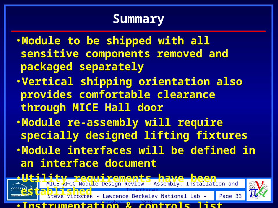
Summary
•Module to be shipped with all sensitive components removed and packaged separately
•Vertical shipping orientation also provides comfortable clearance through MICE Hall door
•Module re-assembly will require specially designed lifting fixtures
•Module interfaces will be defined in an interface document
•Utility requirements have been established
•Instrumentation & controls list being compiled