ASSEMBLY DIAGRAM AND ASSEMBLY REFERENCE ULTIMA … · ASSEMBLY DIAGRAM AND ASSEMBLY REFERENCE...
9
ASSEMBLY DIAGRAM AND ASSEMBLY REFERENCE ULTIMA “BAGGER” 2” BELT DRIVE UNITS FLT, FLH & FXR MODELS 1990-2006 Part # 58-853 BAGGER 2” BILLET BELT DRIVE ASSEMBLY, POLISHED REV 10-22-14
Transcript of ASSEMBLY DIAGRAM AND ASSEMBLY REFERENCE ULTIMA … · ASSEMBLY DIAGRAM AND ASSEMBLY REFERENCE...

ASSEMBLY DIAGRAM AND ASSEMBLY REFERENCE ULTIMA “BAGGER” 2” BELT DRIVE UNITS
FLT, FLH & FXR MODELS 1990-2006
Part # 58-853 BAGGER 2” BILLET BELT DRIVE ASSEMBLY,
POLISHED
REV 10-22-14
ASSEMBLY DIAGRAM AND ASSEMBLY REFERENCE ULTIMA 8MM BELT DRIVE UNITS
BELT DRIVE PRODUCTSWARRANTY PROVISIONSUltima’s® component parts used in our belt drives are guaranteed to the original purchaser to be free of manufacturing defects in materials and workmanshipfor a period of twelve (12) months from the date of purchase through Midwest Motorcycle Supply.Merchandise that fails to conform to these conditions will be repaired by Ultima® if the parts are returned to Midwest Motorcycle Supply by the purchaserwithin the 12-month warranty period or within 10 days thereafter.Some problems can be rectified by a telephone call and need no further course of action. A part that is suspected of being defective must not be replaced bya Dealer without prior authorization from Midwest Motorcycle Supply. If it is deemed necessary for Ultima® to make an evaluation to determine whether thepart was defective, it must be packaged properly to prevent further damage and be returned prepaid to Midwest Motorcycle Supply with a copy of the originalinvoice of purchase, detailed letter outlining the nature of the problem, how the part was used and the circumstances at the time of failure. If, after an evalua-tion has been made by Ultima® and the part was found to be defective, repair or replacement will be granted at Ultima’s® discretion.
ADDITIONAL WARRANTY PROVISIONS:1. Ultima® shall have no obligation in the event an Ultima® part is modified by any other person or organization.2. Ultima® shall have no obligation in the event an Ultima® part becomes defective in whole or in part as a result of improper installation, improper mainte-nance, improper use, abnormal operation, or any other misuse or mistreatment of the Ultima® part.3. Ultima® shall not be liable for any consequential or incidental damage resulting from the failure of an Ultima® part, the breach of any warranties, the failureto deliver, delay in delivery, delivery in non-conforming condition, or for any other breach of contract or duty between Ultima® and a customer.4. These Diagrams are provided for a reference only and in no way imply that this part is suitable for the applications it is being installed to. The Part #’sthese diagrams reference were designed to fit OEM FLT & FXR style motorcycles made from 1990-2006.
PROFESSIONAL INSTALLATION REQUIREMENTS:Ultima® Belt Drives should be installed by trained professional mechanics into a motorcycle in which they were intended for use. Failure to do so may resultin injury and even death. It is the customer’s responsibility to insure their mechanic has proper training.
I. PREPARATION FOR ASSEMBLY
Before installing the Ultima® belt drive system you must remove your entire existing primary drive. This also includes the pressed on trans-mission mainshaft race used with chain drive inner primary bearings. Always disconnect battery before removing or installing primarydrive systems.
The Ultima® belt drive system comes with a 1989-1993 type starter drive shaft which will fit 89’-06’ starter models. Starter bolts are availableto accomodate 89’-06’ starters. We also suggest using any of our heavy duty Ultima® Thunder Fire® starters part # 70-220 thru 70-229which incorporate both 89/93 and 94/06’ style drive shaft bolt arrangements. These starters are available in 1.4, 1.75, 2.0 and 2.4 Kw config-urations.
At this time we suggest inspection of your charging system. While you are inspecting the alternator we highly recommend that you install a new crankshaft seal on the engine replacing theexisting seal with a high quality double lip seal and installing the seal with the steel face out. Belt drive units require a dry environ-ment free from oil and by flipping the oil seal you ensure any crankcase pressure and oil will stay in your engine. This is also a great time toinspect the transmission sprocket and seal for wear and to ensure the sprocket is tight.
ASSEMBLY INSTRUCTIONS
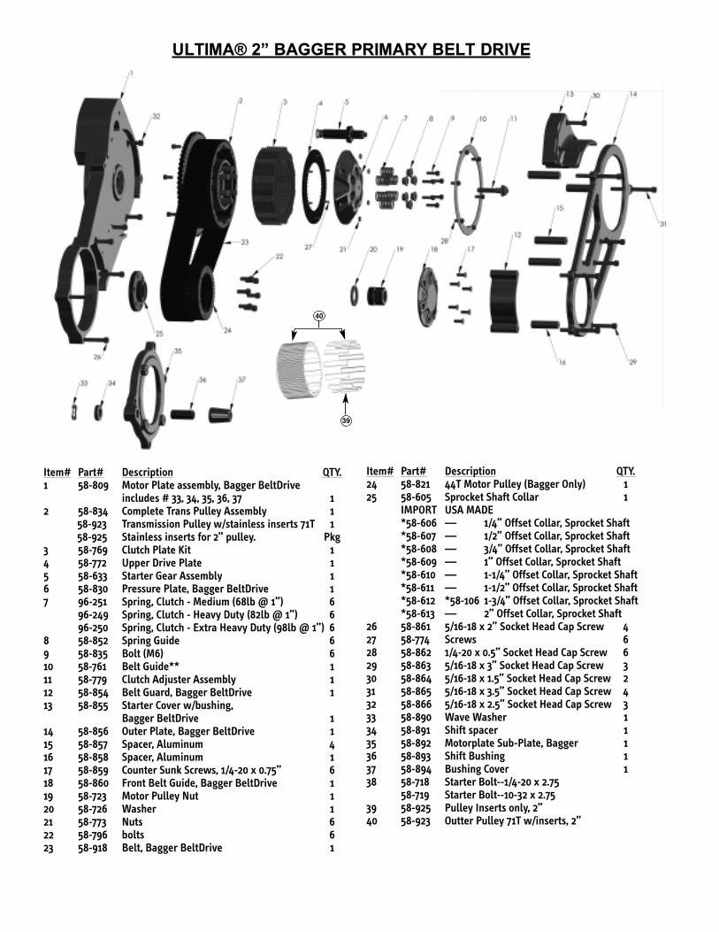
ULTIMA® 2” BAGGER PRIMARY BELT DRIVE
Item# Part# Description QTY.1 58-809 Motor Plate assembly, Bagger BeltDrive
includes # 33, 34, 35, 36, 37 12 58-834 Complete Trans Pulley Assembly 1
58-923 Transmission Pulley w/stainless inserts 71T 158-925 Stainless inserts for 2” pulley. Pkg
3 58-769 Clutch Plate Kit 14 58-772 Upper Drive Plate 15 58-633 Starter Gear Assembly 16 58-830 Pressure Plate, Bagger BeltDrive 1 7 96-251 Spring, Clutch - Medium (68lb @ 1”) 6
96-249 Spring, Clutch - Heavy Duty (82lb @ 1”) 696-250 Spring, Clutch - Extra Heavy Duty (98lb @ 1”) 6
8 58-852 Spring Guide 69 58-835 Bolt (M6) 610 58-761 Belt Guide** 111 58-779 Clutch Adjuster Assembly 112 58-854 Belt Guard, Bagger BeltDrive 113 58-855 Starter Cover w/bushing,
Bagger BeltDrive 114 58-856 Outer Plate, Bagger BeltDrive 115 58-857 Spacer, Aluminum 416 58-858 Spacer, Aluminum 117 58-859 Counter Sunk Screws, 1/4-20 x 0.75” 618 58-860 Front Belt Guide, Bagger BeltDrive 119 58-723 Motor Pulley Nut 120 58-726 Washer 121 58-773 Nuts 622 58-796 bolts 623 58-918 Belt, Bagger BeltDrive 1
Item# Part# Description QTY.24 58-821 44T Motor Pulley (Bagger Only) 125 58-605 Sprocket Shaft Collar 1
IMPORT USA MADE*58-606 — 1/4” Offset Collar, Sprocket Shaft*58-607 — 1/2” Offset Collar, Sprocket Shaft*58-608 — 3/4” Offset Collar, Sprocket Shaft*58-609 — 1” Offset Collar, Sprocket Shaft*58-610 — 1-1/4” Offset Collar, Sprocket Shaft*58-611 — 1-1/2” Offset Collar, Sprocket Shaft*58-612 *58-106 1-3/4” Offset Collar, Sprocket Shaft*58-613 — 2” Offset Collar, Sprocket Shaft
26 58-861 5/16-18 x 2” Socket Head Cap Screw 427 58-774 Screws 628 58-862 1/4-20 x 0.5” Socket Head Cap Screw 629 58-863 5/16-18 x 3” Socket Head Cap Screw 330 58-864 5/16-18 x 1.5” Socket Head Cap Screw 231 58-865 5/16-18 x 3.5” Socket Head Cap Screw 432 58-866 5/16-18 x 2.5” Socket Head Cap Screw 333 58-890 Wave Washer 134 58-891 Shift spacer 135 58-892 Motorplate Sub-Plate, Bagger 136 58-893 Shift Bushing 137 58-894 Bushing Cover 138 58-718 Starter Bolt--1/4-20 x 2.75
58-719 Starter Bolt--10-32 x 2.7539 58-925 Pulley Inserts only, 2”40 58-923 Outter Pulley 71T w/inserts, 2”
39
40
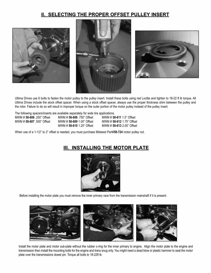
II. SELECTING THE PROPER OFFSET PULLEY INSERT
Ultima Drives use 6 bolts to fasten the motor pulley to the pulley insert. Install these bolts using red Loctite and tighten to 18-22 ft lb torque. AllUltima Drives include the stock offset spacer. When using a stock offset spacer, always use the proper thickness shim between the pulley andthe rotor. Failure to do so will result in improper torque on the outer portion of the motor pulley instead of the pulley insert.
The following spacers/inserts are available separately for wide tire applications.MWM # 58-606 .250” Offset MWM # 58-608 .750” Offset MWM # 58-611 1.5” OffsetMWM # 58-607 .500” Offset MWM # 58-609 1.00” Offset MWM # 58-612 1.75” Offset
MWM # 58-610 1.25” Offset MWM # 58-613 2.00” Offset
When use of a 1-1/2” to 2” offset is needed, you must purchase Midwest Part#58-724 motor pulley nut.
III. INSTALLING THE MOTOR PLATE
Before installing the motor plate you must remove the inner primary race from the transmission mainshaft if it is present.
Install the motor plate and motor sub-plate without the rubber o-ring for the inner primary to engine. Align the motor plate to the engine andtransmission then install the mounting bolts for the engine and trans snug only. You might need a dead blow or plastic hammer to seat the motorplate over the transmissions dowel pin. Torque all bolts to 18-22ft lb.
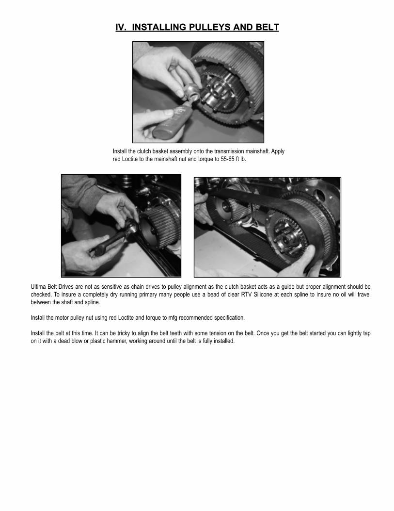
IV. INSTALLING PULLEYS AND BELT
Install the clutch basket assembly onto the transmission mainshaft. Applyred Loctite to the mainshaft nut and torque to 55-65 ft lb.
Ultima Belt Drives are not as sensitive as chain drives to pulley alignment as the clutch basket acts as a guide but proper alignment should bechecked. To insure a completely dry running primary many people use a bead of clear RTV Silicone at each spline to insure no oil will travelbetween the shaft and spline.
Install the motor pulley nut using red Loctite and torque to mfg recommended specification.
Install the belt at this time. It can be tricky to align the belt teeth with some tension on the belt. Once you get the belt started you can lightly tapon it with a dead blow or plastic hammer, working around until the belt is fully installed.

Align the witness marks on the pressure plate and inner clutch hub as shown when installing pressure plate.This will insure clutch hub studs will be centered in the appropriate pressure plate holes.
witness marks
After installing the pressure plate, install clutch springs w/supplied spring collars and narrow-headed 1/4-20 bolts.Install using blue Loctite. Spring collars should bottom on clutch hub studs. Torque to 120 in-lbs.
In higher horsepower applications, heavier springs are available. Midwest Part#96-249 (82lbs @ 1”)Midwest Part#96-250 (98lbs @ 1”)
V. INSTALLING THE CLUTCH COMPONENTS
Ultima 2” belt drives utilize 8 of the old style 900cc sportster steel drive plates and 8 special size fiber plates designed to provide avery adjustable clutch package. When installing the clutch pack install the thick .119” steel plate first then alternate fiber/steel. Thelast plate you install should be fiber.
Check the pressure plate screws to ensure they are all tight and the heads of the bolts are sitting below the plate surface.
Install the clutch adjusting screw using a small amount of high temp grease or anti-sieze on the thread and on the clutch pushrodend. Don’t get too much grease out there –Remember this is a DRY clutch.
NOTE: CENTER PUSHROD IS REQUIRED
The center clutch push rods (located in the transmis-sion main shaft) may need to be changed dependingon setup. Below is a list of availble sizes.PART# LENGTH DESCRIPTION96-442 11.375” 1987-1989 5 speed96-538 10.8125” 1990+ 5 speed96-469 11.875” 1985+ 5 & 6 speed
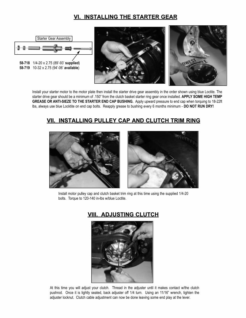
Install your starter motor to the motor plate then install the starter drive gear assembly in the order shown using blue Loctite. Thestarter drive gear should be a minimum of .150” from the clutch basket starter ring gear once installed. APPLY SOME HIGH TEMPGREASE OR ANTI-SIEZE TO THE STARTER END CAP BUSHING. Apply upward pressure to end cap when torquing to 18-22ftlbs, always use blue Locktite on end cap bolts. Reapply grease to bushing every 6 months minimum - DO NOT RUN DRY!
VI. INSTALLING THE STARTER GEAR
Starter Gear Assembly
58-718 1/4-20 x 2.75 (89’-93’ supplied)58-719 10-32 x 2.75 (94’-06’ available)
VII. INSTALLING PULLEY CAP AND CLUTCH TRIM RING
Install motor pulley cap and clutch basket trim ring at this time using the supplied 1/4-20bolts. Torque to 120-140 in-lbs w/blue Loctite.
VIII. ADJUSTING CLUTCH
At this time you will adjust your clutch. Thread in the adjuster until it makes contact w/the clutchpushrod. Once it is lightly seated, back adjuster off 1/4 turn. Using an 11/16” wrench, tighten theadjuster locknut. Clutch cable adjustment can now be done leaving some end play at the lever.
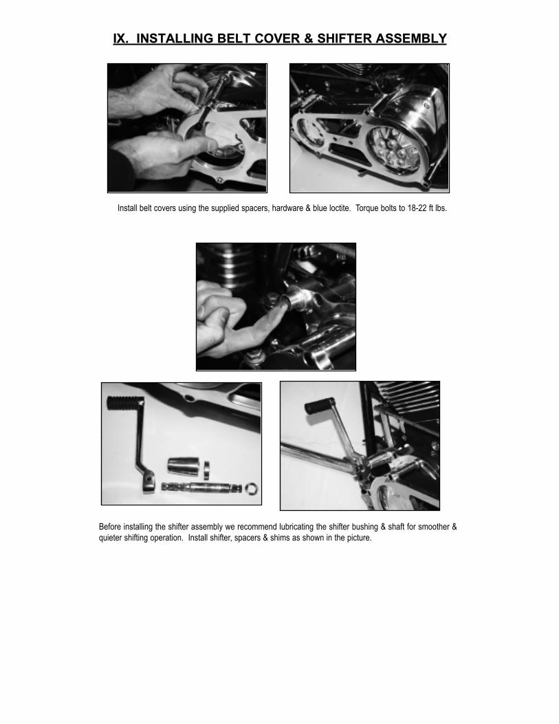
IX. INSTALLING BELT COVER & SHIFTER ASSEMBLY
Install belt covers using the supplied spacers, hardware & blue loctite. Torque bolts to 18-22 ft lbs.
Before installing the shifter assembly we recommend lubricating the shifter bushing & shaft for smoother &quieter shifting operation. Install shifter, spacers & shims as shown in the picture.

Check your kickstand clearance to the belt by pushing down on the belt then adding at lease 1/2’ of travel.Use MWM # 5-190 adjustable kickstand leg stop if needed. This is an important safety check and shouldbe performed before initial startup.
XI. KICKSTAND CONSIDERATIONS
X. FLOORBOARD CONSIDERATIONS
Ultima 2” Bagger Belt Drives are designed to work with stock floorboards. We recommend verifyingthere are no clearance issues w/your floorboards at this time. Shim/space as necessary.
Shown without the floorboards installed.