Assembly and operating instructions - Wolf...
52
Assembly and operating instructions Gas condensing boilers MGK-130 MGK-170 MGK-210 MGK-250 MGK-300 Document no. 3062880_201305 Subject to technical modifications These installation instructions are to be retained by the user. We cannot accept any warranty claims if these operating instructions have not been observed. GB Wolf GmbH · Postfach 1380 · D-84048 Mainburg · Tel. +49-8751/74-0 · Fax +49-8751/741600 · Internet: www.wolf-heiztechnik.de
Transcript of Assembly and operating instructions - Wolf...
Assembly and operating instructions
Gas condensing boilers
MGK-130MGK-170MGK-210MGK-250MGK-300
Document no. 3062880_201305 Subjecttotechnicalmodifications
These installation instructions are to be retained by the user.We cannot accept any warranty claims if these operating instructions have not been observed.
GB
Wolf GmbH · Postfach 1380 · D-84048 Mainburg · Tel. +49-8751/74-0 · Fax +49-8751/741600 · Internet: www.wolf-heiztechnik.de
2 3062880_201305
ContentsContents ................................................................................................. Page
Safetyinstructions .......................................................................................3-4
Standardsandregulations...........................................................................5-6
Layout MGK....................................................................................................6
Specification ...................................................................................................7
Control/Function/Operation .....................................................................8-9
Deliveredcondition/Connections ................................................................10
Installationinstructions ................................................................................. 11
Installationinstructions/Dimensions ...........................................................12
Dismantling,casing ......................................................................................13
Boilersystempipework.................................................................................14
Installation ...............................................................................................15-17
Installation,combustionairsupply/fluesystem ..........................................18
Electricalconnection................................................................................18-22
Fillingthesystem/fillingthesiphon .............................................................23
Checkingthegassupplypressure ...............................................................24
Commissioning/SettingtheBUSaddress...................................................25
Displaying/modifyingcontrolparameters....................................................26
Limitingthemaximumoutput........................................................................27
Changingthegastype/CO2 settings ......................................................28-30
Testingthecombustionparameters..............................................................31
Commissioningreport...................................................................................32
Technicalinformation,watertreatment ....................................................33-34
Systemlog ....................................................................................................35
Engineeringdata ..........................................................................................36
Engineeringinformation,combustionair/fluegasrouting......................37-43
WiringdiagramMGK-130 .............................................................................44
WiringdiagramMGK-170-300 ....................................................................45
Troubleshooting .......................................................................................46-47
Resistancetable ...........................................................................................48
Notice ......................................................................................................49-51
ECdeclarationofconformity ........................................................................52

33062880_201305
The following symbols and references are used in conjunction with these important instructions concerning personal safety, as well as operational reliability.
"Safety instructions" are instructions with which you must comply exactly, to prevent risks and injuries to individuals and material losses on the boiler.
Danger from 'live' electrical components! NB: Switch OFF the ON/OFF switch
before removing the casing. Never touch electrical components or
contacts when the ON/OFF switch is in the ON position! This results in a risk of electrocution that may lead to injury or death.
The main supply terminals are 'live' even when the ON/OFF switch is in the OFF position.
"NB" indicates technical instructions that you must observe to prevent material losses and malfunctions on the boiler.
This unit is neither due to be used by persons (in-cluding children) with physical, sensoric or mental handicaps nor by users missing the required experi-ence and/or knowledge unless being supervised and instructed about its application by a person being }responsible for their security.
NB
Safety instructions
Fig.:GascombinationvalveMGK-170/210/250/300DangerfromelectricalvoltageEscapinggasmaycausepoisoningortheriskofexplosion
Fig.:Ignitiontransformer,highvoltageignitionelectrode,combustionchamberDangerfrom'live'electricalcomponents,riskofburningthroughhotcomponents
Fig.:JunctionboxMGK-170/210/250/300Dangerfromelectricalvoltage

4 3062880_201305
The following regulations and rules have to be adhered toduring installation, commissioning, maintenance and service:
Theinstallationmayonlybeoperatedintechnicallyperfectcondition.Pertur-bancesanddamagesaffectingsafetyhavetobeeliminatedatonce.
Whensetting thesanitaryhotwater temperatureabove60°Corwhenacti-vatingtheanti-legionellofunctionwithatemperatureexceeding60°Cithastoprovidedacorrespondingfreshwateradmixture(riskofscalding).
Theperfectfunctionoftheelectricalequipmenthastobecheckedperiodically.
Perturbancesanddamagesmayonlybeeliminatedbyexperttechnicians.
DamagedcomponentsmayonlybereplacedbygenuineWolfspareparts.
Prescriptedelectricalfusevalueshavetobeadheredto(seetechnicaldata).
AnydamageresultingfromtechnicalmodificationstoWolfcontrolunitsisex-cludedfromourliability.
TheappropriateEuropeanandelectricalsafetyregulationsaswellasthecor-respondingregulationsoftheEnergySupplyCompanyhavetobeadheredtoduringtheinstallationandexecutionofelectricalworks.
Itisnotallowedtoremove,shuntorinvalidatesafetyandmonitoringfacilities!
Safety instructions

53062880_201305
Note: Please read these instructions carefully before the installation and keep them in a safe place. Please also note the technical information in the appendix.
Requirements
Theinstallationoftheboilermustbeinaccordancewiththerelevant requirements ofGasSafety (Installation andUse)Regulations1998,HealthandSafetyDocumentNo.635(TheElectricityatWorkRegulations1989),BS7671(IEEWiringRegulations)andtheWaterSupply(WaterFitting)Regulations1999,orTheWaterBylaws2000(Scotland). ItshouldalsobeinaccordancewiththerelevantrequirementsoftheLocalAuthority, BuildingRegulations, including amendments totheApprovedDocumentsPart L and J 2002,TheBuildingRegulations(Scotland),TheBuildingRegulations(NorthernIreland)and therelevant recommendationsof the followingBritishStandards:
BS5440: Flues and ventilation of gas fired boilers notexceeding70kWnet:
- Part1:Flues - Part2:VentilationBS5449: Specificationforforcedcirculationhotwaterfor
domesticpremises.BS5546: Specification for gas hot water supplies for
domesticpremises.BS6700: Servicessupplyingwaterfordomesticusewithin
buildingsandtheircurtilages.BS6798: Specificationfor installationofgasfiredboilers
notexceeding60kWinput.BS6891: Specificationforinstallationoflowpressuregas
pipeworkupto28mm(R1")indomesticpremises(2nd familygas).
BS7593: Treatmentofwaterindomestichotwatercentralheatingsystems.
InstituteofGasEngineersPublicationIGE/UP/7/1998:"Guideforgasinstallationsintimberframedhousing"
Important:TheappliancemustbeinstalledandservicedbyacompetentpersonasstatedintheGasSafety(InstallationandUse)Regulations1998. In IE, the installationmust beinaccordancewith thecurrenteditionof I.S,813"DomesticGas Installations", the current BuildingRegulations andreferenceshouldbemadetothecurrentECIrulesforelectricalinstallation.
Whentighteningorlooseningthreadedconnectionsalwaysusesuitableopen-endedspanners(notpipewrench,orextensions,etc.).Incorrectuseand/orunsuitabletoolscanleadtodamage(e.g.gasorwaterleaks)!
Any damage or loss resulting from technicalmodifications to thecontrol unit or to thecontrolcomponentsareexcludedfromourliability.Incorrectusecanleadtoarisktolifeandlimbortoariskofmateriallosses.
Obtain the permission of your mains gas supplier and flue gas inspector prior to the installation of Wolf gas fired boilers [where appropriate].
Wolfgasfiredboilersmustonlybeinstalledbyarecognisedheating contractor. This heating contractor will also beresponsiblefortheproperinstallationandcommissioningoftheheatingsystem.
The following regulations, rules and guidelinesmust beobservedduringinstallation:- VDE0722/EN50165 Electr ical equipment of heat
generators with non-electricalheatingsystems
- DINEN12828 Heating systems in buildings,designinghotwaterheatingsystems
-EN60335-1 Safety of electrical equipment fordomesticuseandsimilarpurposes
- VDE0470/EN60529Protectionthroughhousings
- EN12831 Methodforcalculationofthedesignheat load
- EN13384 Chimneys - Thermal and fluiddynamic calculation method
Standards and regulations
6 3062880_201305
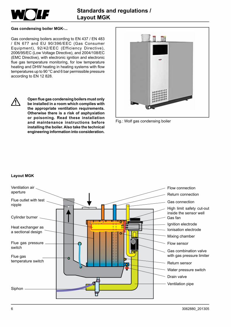
Gas condensing boiler MGK-...
GascondensingboilersaccordingtoEN437/EN483/ EN 677 and EU 90/396/EEC (Gas ConsumerEquipment), 92/42/EEC (Efficiency Directive), 2006/95/EC(LowVoltageDirective),and2004/108/EC(EMCDirective),withelectronicignitionandelectronicfluegas temperaturemonitoring, for low temperatureheatingandDHWheatinginheatingsystemswithflowtemperaturesupto90°Cand6barpermissiblepressureaccordingtoEN12828.
Standards and regulations /Layout MGK
Open flue gas condensing boilers must only be installed in a room which complies with the appropriate ventilation requirements. Otherwise there is a risk of asphyxiation or poisoning. Read these installation and maintenance instructions before installing the boiler. Also take the technical engineering information into consideration.
Fig.:Wolfgascondensingboiler
Flueoutletwithtestnipple
Heatexchangerasasectionaldesign
FlowconnectionReturnconnection
High limit safetycut-outinsidethesensorwell
Gasconnection
IgnitionelectrodeIonisationelectrode
Gasfan
Mixingchamber
Cylinderburner
Flowsensor
Gascombinationvalvewithgaspressurelimiter
Returnsensor
Waterpressureswitch
Ventilationpipe
Drainvalve
Siphon
Fluegastemperatureswitch
Flue gas pressureswitch
Ventilationairaperture
Layout MGK
73062880_201305
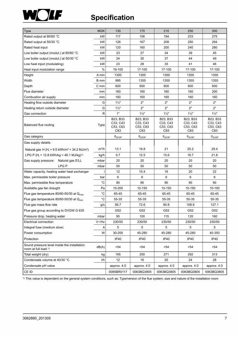
SpecificationType MGK 130 170 210 250 300
Ratedoutputat80/60°C kW 117 156 194 233 275
Ratedoutputat50/30°C kW 126 167 208 250 294
Rated heat input kW 120 160 200 240 280
Lowboileroutput(modul.)at80/60°C kW 23 27 34 39 45
Lowboileroutput(modul.)at50/30°C kW 24 30 37 44 49
Lowheatinput(modulating) kW 23 28 35 41 46
Heatinputmodulationrange % 19-100 17-100 17-100 17-100 17-100
Height A mm 1300 1300 1300 1300 1300
Width B mm 995 1355 1355 1355 1355
Depth C mm 600 600 600 600 600
Fluediameter mm 160 160 160 160 200
Combustionairsupply mm 160 160 160 160 160
Heatingflowoutsidediameter G 1½" 2" 2" 2" 2"
Heatingreturnoutsidediameter G 1½" 2" 2" 2" 2"
Gasconnection R 1" 1½" 1½" 1½" 1½"
Balancedfluerouting Type
B23,B33C33,C43C53,C63
C83
B23,B33C33,C43C53,C63
C83
B23,B33C33,C43C53,C63
C83
B23,B33C33,C43C53,C63
C83
B23,B33C33,C43C53,C63
C83
Gascategory II2H3P II2H3P II2H3P II2H3P II2H3P
Gassupplydetails:
Naturalgas H(Hi=9.5kWh/m³=34.2MJ/m³) m³/h 13.1 16.8 21 25.2 29.4
LPGP(Hi=12.8kWh/kg=46.1MJ/kg)1) kg/h 9.7 12.5 15.6 18.7 21.8
Gassupplypressure: NaturalgasE/LL mbar 20 20 20 20 20
LPGP mbar 50 50 50 50 50
Watercapacity,heatingwaterheatexchanger l 12 15.4 16 20 22
Max.permissibleboilerpressure bar 6 6 6 6 6
Max.permissibleflowtemperature °C 90 90 90 90 90
Availablegasfandraught Pa 10-200 10-150 10-150 10-150 10-150
Fluegastemperature80/60-50/30atQmax °C 65-45 65-45 65-45 65-45 65-45
Fluegastemperature80/60-50/30atQmin °C 55-35 55-35 55-35 55-35 55-35
Fluegasmassflowrate g/s 56.7 72.6 90.8 108.9 127.1
FluegasgroupaccordingtoDVGWG635 G52 G52 G52 G52 G52
Pressuredrop,heatingwater mbar 95 100 115 135 160
Electricalconnection V~/Hz 230/50 230/50 230/50 230/50 230/50
Integralfuse(mediumslow) A 5 5 5 5 5
Powerconsumption W 30-200 45-280 45-280 45-280 45-350
Protection IP40 IP40 IP40 IP40 IP40
Soundpressurelevelinsidetheinstallationroomatfullload1) dB(A) <54 <54 <54 <54 <54
Totalweight(dry) kg 195 250 271 292 313
Condensatevolumeat40/30°C l/h 12 16 20 24 28
CondensatepHvalue approx.4.0 approx.4.0 approx.4.0 approx.4.0 approx.4.0
CE ID 0085BR0117 0063BQ3805 0063BQ3805 0063BQ3805 0063BQ3805
1) Thisvalueisdependentonthegeneralsystemconditions,suchas:Type/versionofthefluesystem,sizeandnatureoftheinstallationroom

8 3062880_201305
Control / Function / Operation
ON/OFF switchThecondensingboilerisOFFinposition0.
ON/OFFswitch DHWtemperatureselector
Resetbutton
Heatingwatertemperatureselector
Illuminatedring
Thermometer
Reset Afaultisresetbypressingtheresetbuttonwhichwillalsorestartthesystem.Pressingtheresetbuttonre-activatesthesystem,iftherewasnofault.
Illuminated status indicator ring
DHW temperature selection (onlywith3-wayvalve)WhengascondensingboilersarecombinedwithaDHWcylinder,setting1-9corresponds toacylinder temperatureof15-65 °C.TheDHW temperatureselectorsettingbecomesineffectivewhenthesystemiscombinedwithadigitalroomthermostatoraweather-compensatedcontroller.Thetemperaturewillthenbeselectedatthecontroller(accessory).
91
2 8
3 7
4 65
Heating water temperature selectionSettings2-8correspond,whenfactory-set,toaheatingwatertemperatureof 20-85°C.Theheatingwaterthermostatsettingbecomesineffectivewhenthesystemiscombinedwithadigitalroomthermostatoraweather-compensatedcontroller.
2 8
3 7
4 65
Display ExplanationFlashinggreen
Standby (powersupplyON,noheatdemand)
Constantgreenlight
Heatdemand:Pumprunning; burnerOFF
Flashingyellow
Emissionstestmode
Constantyellowlight
BurnerON;flamesteady
Flashingred Fault
93062880_201305
Control / Function / Operation Settings
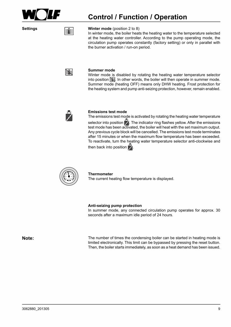
Anti-seizing pump protectionIn summermode,anyconnectedcirculationpumpoperates forapprox.30secondsafteramaximumidleperiodof24hours.
Note: Thenumberoftimesthecondensingboilercanbestartedinheatingmodeislimitedelectronically.Thislimitcanbebypassedbypressingtheresetbutton.Then,theboilerstartsimmediately,assoonasaheatdemandhasbeenissued.
Winter mode(position2to8)Inwintermode,theboilerheatstheheatingwatertothetemperatureselectedat theheatingwatercontroller.According to thepumpoperatingmode, thecirculationpumpoperatesconstantly(factorysetting)oronlyinparallelwiththeburneractivation/run-onperiod.
Summer modeWintermode isdisabledbyrotating theheatingwater temperatureselectorintoposition .Inotherwords,theboilerwillthenoperateinsummermode.Summermode(heatingOFF)meansonlyDHWheating.Frostprotectionfortheheatingsystemandpumpanti-seizingprotection,however,remainenabled.
Thermometer Thecurrentheatingflowtemperatureisdisplayed.
Emissions test modeTheemissionstestmodeisactivatedbyrotatingtheheatingwatertemperatureselectorintoposition .Theindicatorringflashesyellow.Aftertheemissionstestmodehasbeenactivated,theboilerwillheatwiththesetmaximumoutput.Anypreviouscycleblockwillbecancelled.Theemissionstestmodeterminatesafter15minutesorwhenthemaximumflowtemperaturehasbeenexceeded.Toreactivate,turntheheatingwatertemperatureselectoranti-clockwiseandthenbackintoposition .
10 3062880_201305
Delivered condition / ConnectionsDelivered condition
Thestandarddeliveryincludes:
1 Gascondensingboiler,fullywired 1 Technicalguideandinstallationinstructions 1 Operatinginstructions 4 Liftingslings
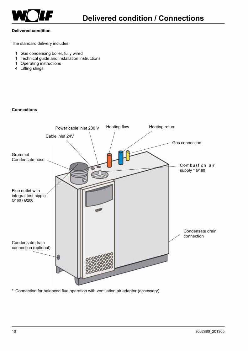
Connections
FlueoutletwithintegraltestnippleØ160/Ø200
HeatingreturnHeatingflow
Gasconnection
Combust ion ai rsupply*Ø160
Cableinlet24V
Powercableinlet230V
Condensatedrainconnection
Condensatedrainconnection(optional)
GrommetCondensatehose
*Connectionforbalancedflueoperationwithventilationairadaptor(accessory)
113062880_201305
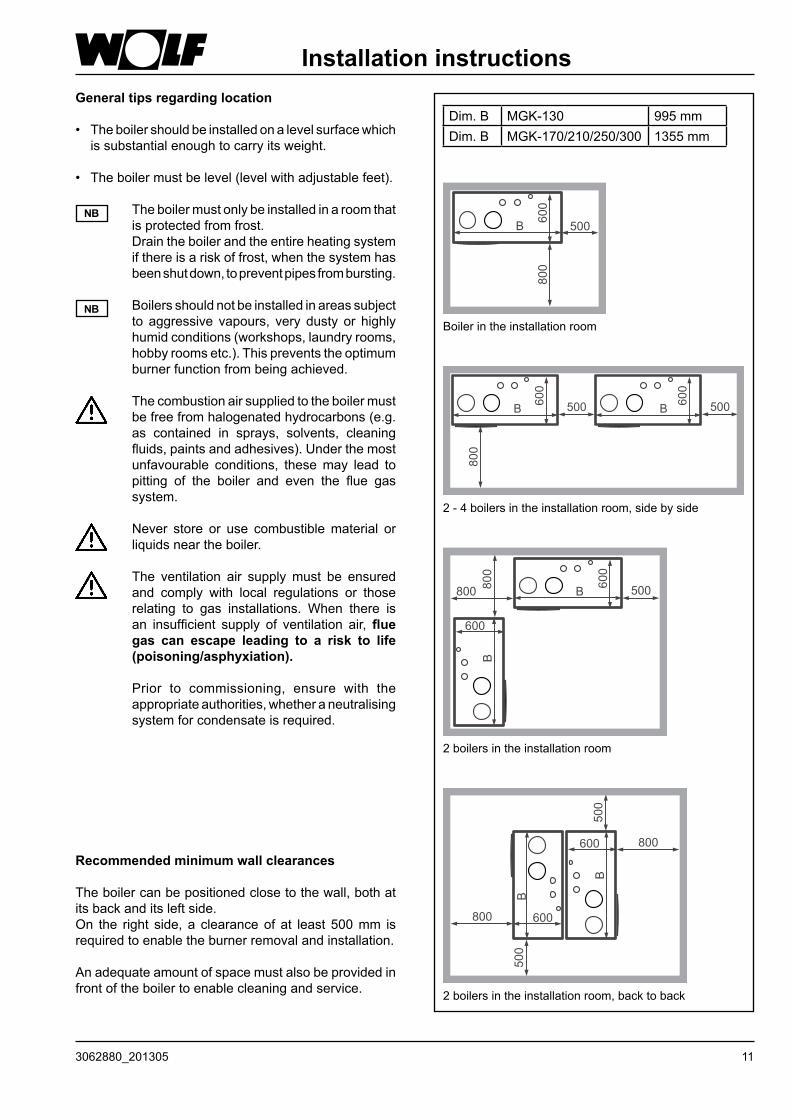
Recommended minimum wall clearances
Theboilercanbepositionedclosetothewall,bothatitsbackanditsleftside.On the right side, a clearanceof at least 500mm isrequiredtoenabletheburnerremovalandinstallation.
Anadequateamountofspacemustalsobeprovidedinfrontoftheboilertoenablecleaningandservice.
Installation instructionsGeneral tips regarding location
• Theboilershouldbeinstalledonalevelsurfacewhichissubstantialenoughtocarryitsweight.
• Theboilermustbelevel(levelwithadjustablefeet).
Theboilermustonlybeinstalledinaroomthatisprotectedfromfrost.Draintheboilerandtheentireheatingsystemifthereisariskoffrost,whenthesystemhasbeenshutdown,topreventpipesfrombursting.
Boilersshouldnotbeinstalledinareassubjectto aggressive vapours, very dusty or highlyhumidconditions(workshops,laundryrooms,hobbyroomsetc.).Thispreventstheoptimumburnerfunctionfrombeingachieved.
Thecombustionairsuppliedtotheboilermustbefreefromhalogenatedhydrocarbons(e.g.as contained in sprays, solvents, cleaningfluids,paintsandadhesives).Underthemostunfavourable conditions, thesemay lead topitting of the boiler and even the flue gassystem.
Never store or use combustiblematerial orliquidsneartheboiler.
The ventilation air supplymust be ensuredand comply with local regulations or thoserelating to gas installations. When there isan insufficient supply of ventilation air, flue gas can escape leading to a risk to life (poisoning/asphyxiation).
Prior to commissioning, ensure with theappropriateauthorities,whetheraneutralisingsystemforcondensateisrequired.
NB
NB
2boilersintheinstallationroom,backtoback
2boilersintheinstallationroom
2-4boilersintheinstallationroom,sidebyside
Boilerintheinstallationroom
Dim. B MGK-130 995 mmDim. B MGK-170/210/250/300 1355 mm
12 3062880_201305
Installation information / Dimensions
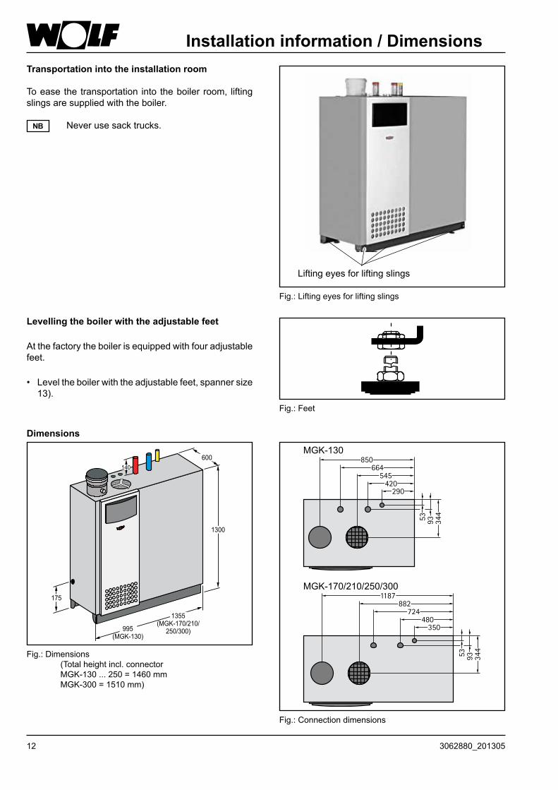
Levelling the boiler with the adjustable feet
Atthefactorytheboilerisequippedwithfouradjustablefeet.
• Leveltheboilerwiththeadjustablefeet,spannersize13).
Fig.:Feet
Transportation into the installation room
Toeasethetransportation into theboiler room, liftingslingsaresuppliedwiththeboiler.
Neverusesacktrucks.NB
Dimensions
Fig.:Connectiondimensions
MGK-130
MGK-170/210/250/300
Fig.:Dimensions (Totalheightincl.connector MGK-130 ... 250 = 1460 mm MGK-300=1510mm)
Fig.:Liftingeyesforliftingslings
Liftingeyesforliftingslings
133062880_201305
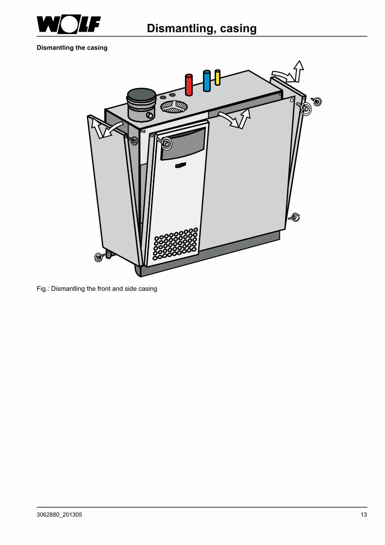
Dismantling, casingDismantling the casing
Fig.:Dismantlingthefrontandsidecasing
14 3062880_201305
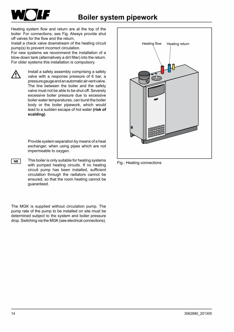
Boiler system pipeworkHeating systemflowand returnareat the topof theboiler.Forconnections,seeFig.Alwaysprovideshutoffvalvesfortheflowandthereturn.Installacheckvalvedownstreamoftheheatingcircuitpump(s)topreventincorrectcirculation.Fornewsystemswerecommendthe installationofablow-downtank(alternativelyadirtfilter)intothereturn.Foroldersystemsthisinstallationiscompulsory.
Installasafetyassemblycomprisingasafetyvalve with a response pressure of 6 bar, apressuregaugeandanautomaticairventvalve.The line between the boiler and the safetyvalvemustnotbeabletobeshutoff.Severelyexcessive boiler pressure due to excessiveboilerwatertemperatures,canbursttheboilerbody or the boiler pipework, which wouldleadtoasuddenescapeofhotwater(risk of scalding).
HeatingreturnHeatingflow
Fig.:Heatingconnections
Providesystemseparationbymeansofaheatexchanger,whenusingpipeswhicharenotimpermeabletooxygen.
Thisboilerisonlysuitableforheatingsystemswith pumped heating circuits. If no heatingcircuit pump has been installed, sufficientcirculation through the radiators cannot beensured,sothattheroomheatingcannotbeguaranteed.
NB
TheMGK is suppliedwithout circulation pump.Thepumprateofthepumptobeinstalledonsitemustbedeterminedsubjecttothesystemandboilerpressuredrop.SwitchingviatheMGK(seeelectricalconnections).
153062880_201305
InstallationNote:Provideadrain&fillvalveatthelowestsystempoint.
Safety equipmentTheminimumsystempressureis1.0bar.Thegascondensingboilersareapprovedexclusivelyforsealedunventedsystemsupto6bar.Themaximumflowtemperatureisfactory-setto85°Candmaybeadjustedto90°Cifrequired.Generally,theflowtemperatureis80°CforDHWoperation.Thereisnoneedforaminimumthroughputatmaximumflowtemperaturesbelow85°C.
Heating water
General requirementsThere is a danger of damage to the wall-mounted boiler leading to the escape of water, poorer heat transmission or corrosion.
- Theheatingsystemistobeflushedthroughbeforetheconnectionofthewallmountedgascondensingboilerinordertoremoveresiduesfromthepipeworksuchasweldingsputter,hemp,putty,sludgedepositsetc.
- Installation of a sieve/dirt trap in the return andregularmaintenanceofthesieve/dirttrap;seeWolfaccessories(5μm).
- Theautomatic vent of theappliancemust beopenduringoperation
- Potablewaterorsaline-freepotablewateristobeusedasfillingandsupplementarywater.Thehardnessofthesystemwatermaynotfallbelow2°dH.Thesystem-specificfillingandsupplementarywaterqualitiesaretobetakenfromthesection‘Watertreatmentplanningnotes’.
- Ahydraulicseparatormustbeprovidedforiftheentryofoxygencannotbeexcluded
- ThepHvalueoftheheatingwatermustliebetween8.2 and 8.5
- Ingeneral,fillingandsupplementarywatermustbesubmittedtoadesalization;softeningviaasingle-stageion exchanger is not permissible.The permissiblemethodsand limit values are to be taken from thesection entitled ‘Water treatment planning notes’(ATTENTION:thelimitvaluesareplant-specific)
- Inhibitorsandanti-freezearenotapproved.- A system logbook is to bemaintained; see ‘Watertreatmentplanningnotes’.
Afterproperfillingofthesystem,thesystemmustbeheatedtothemaximumandthetotalhardnessandpHvaluemeasuredagainandadjusted.Thesevaluesmustbecheckedagainandadjustedafter6-8weeks.
Additional requirements for operation without low-loss header
- SystemswithonlyoneMGK- SludgeseparatorinthedevicereturnoftheMGK- Desalizationoftheheatingwaterto2-3°dH- Control of the calorifier charging only via theMMmodule(configurations1and10)
- CalorifierchargepumpatleastDN25withaliftingheightofatleast6m
- Themax.inlettemperaturemustbesetto75°CwiththeparameterHG08
The water treatment planning notes must be observed, as otherwise damage to the system may occur leading to the escape of water.
Themanufacturercannotacceptanyliabilityfordamagetotheheatexchangerresultingfromoxygendiffusionintotheheatingwater.Inthecasethatoxygencanpenetrateintothesystem,werecommendahydraulicseparatorbyinstallinganintermediateheatexchanger.
Note from VDI 2035
Limescale formation can be influenced above all throughthetypeandmethodofcommissioning.Heatupthesystematthelowestpowerwithanevenandsufficientflowrate.Inthecaseofmulti-boilersystemsitisrecommendedtoputallboilersintooperationatthesametimesothatthetotalamountoflimecannotconcentrateontheheattransfersurfaceofanindividualboiler.
To submit pipework to a leak test:Test pressure on hot water side max. 8 bar.Before the test, close the shut-off valves in the heating circuit to the device, since otherwise the safety valve (accessory) will open at 3 bar. The device has already been tested for leaks at 6 bar in the factory.If there are leaks there is a danger of escape of water leading to damage to property.
Withaspecificsystemvolumeof>50l/KWthetotaldegreeofhardnessmustbeadjusted to2-3°dHusingadesaltingprocess.
16 3062880_201305
Installation
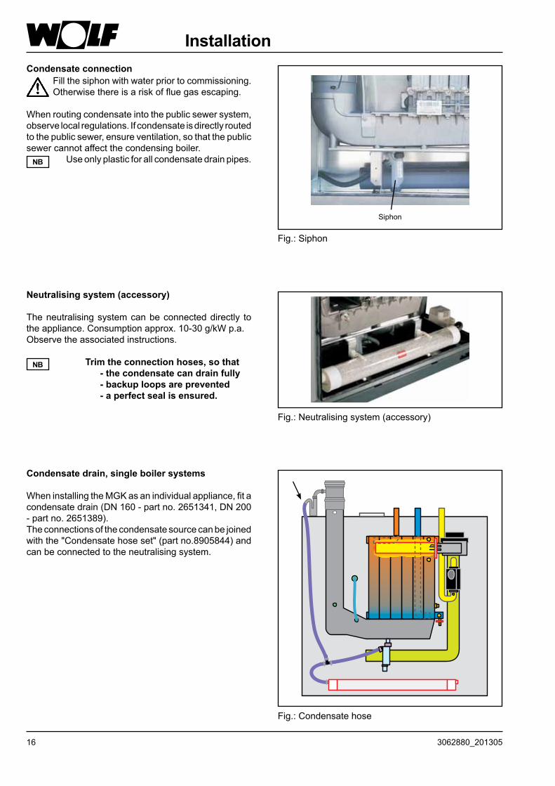
Fig.:Siphon
Siphon
Condensate connection Fillthesiphonwithwaterpriortocommissioning.
Otherwisethereisariskoffluegasescaping.
Whenroutingcondensateintothepublicsewersystem,observelocalregulations.Ifcondensateisdirectlyroutedtothepublicsewer,ensureventilation,sothatthepublicsewercannotaffectthecondensingboiler.
Useonlyplasticforallcondensatedrainpipes.NB
Neutralising system (accessory)
Theneutralisingsystemcanbeconnecteddirectly totheappliance.Consumptionapprox.10-30g/kWp.a.Observetheassociatedinstructions.
Trim the connection hoses, so that- the condensate can drain fully- backup loops are prevented- a perfect seal is ensured.
NB
Fig.:Neutralisingsystem(accessory)
Condensate drain, single boiler systems
WheninstallingtheMGKasanindividualappliance,fitacondensatedrain(DN160-partno.2651341,DN200-partno.2651389).Theconnectionsofthecondensatesourcecanbejoinedwiththe"Condensatehoseset"(partno.8905844)andcanbeconnectedtotheneutralisingsystem.
Fig.:Condensatehose
173062880_201305
Installation
• Priortoinstallation,ensurethattheboilerissettotheavailablegastype.
At the factory, the boiler is set up for natural gas H 15.0: Ws = 11.4 - 15.2 kWh/m3 = 40.9 - 54.7 MJ/m3
Whenchangingthegastype,settheapplianceinaccordancewithchapter"Changingthegastype/CO2settings".
• Onlycommissiontheappliancewhentheratedsupplypressurehasbeenreached.
Gas connectionRoutingthegaspipeaswellasmakingthegasconnectionsmustonlybecarriedoutbyalicensedgasfitter.
Removeallresiduesfromtheheatingpipeworkandthegaslinepriortoconnectingthecondensingboiler,particularlyinoldersystems.Priortocommissioning,testallpipeandgasconnectionsforleaks.Inappropriateinstallationorusingunsuitablecomponentsorassembliesmayleadtogasescaping,whichresultsinariskofpoisoningandexplosion.
InstallagasballvalvewithfireprotectioninthegassupplylineupstreamoftheWolfcondensingboiler.Otherwiseexplosionsmayoccurduringafire.Sizethegassupplylineinaccordancewithlocalregulations.
Check the gas line for tightness without the boiler.Never release the test pressure via the gas valve.
Gas fittings on the appliance may be pressure tested to 150 mbar. Higher pressure may damage the gas train, resulting in a risk of explosion, asphyxiation or poisoning.Close the gas ball valve on the gas condensing boiler to pressure test the gas line.
Mount the gas ball valve in an easily accessible place.
Connection of a Wolf cylinder,solar cylinder SEM or third party cylinder
WerecommendtheMMorKMcontrollersfromtherangeofWolfaccessoriesforoptimumswitchingofheatingcircuitandcylinderprimarypumps.
Whensizingthecylinderensurethatthelowestconstantcylinderoutputcorrespondsatleasttothelowestheatinputfromtheboiler.Asolarcylinder(withoutsolarthermalsystem)canbeconnectedtoincreasetheconstantDHWoutput.Forthis,bothinternalindirectcoilsneedtoreceiveavolumeflowinseries.Otherwiseitcannotbeassuredthatthecylinderwillbefullyheatedup.
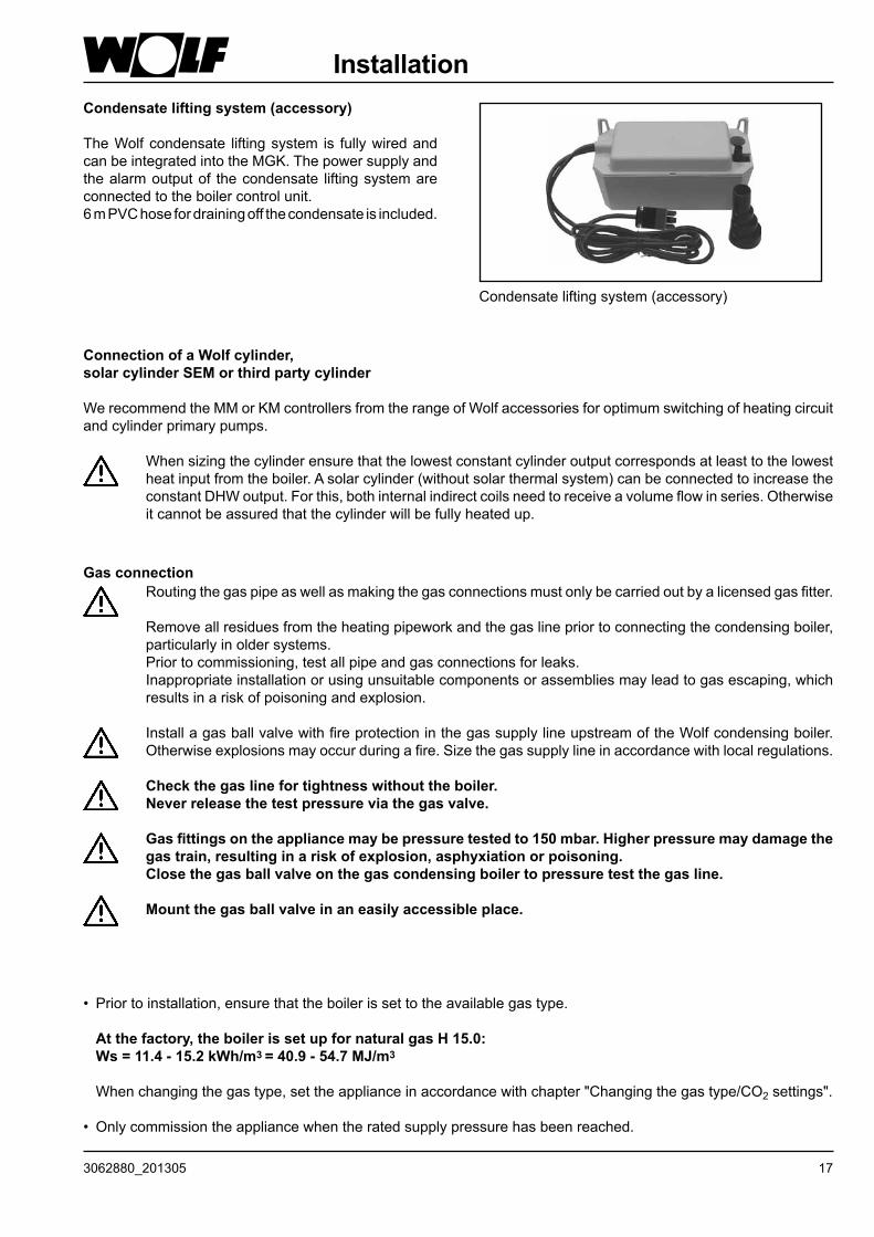
Condensateliftingsystem(accessory)
Condensate lifting system (accessory)
TheWolfcondensate liftingsystem is fullywiredandcanbeintegratedintotheMGK.Thepowersupplyandthealarmoutputof thecondensate liftingsystemareconnectedtotheboilercontrolunit.6mPVChosefordrainingoffthecondensateisincluded.
18 3062880_201305
Installation, combustion air supply / flue system / electrical connection
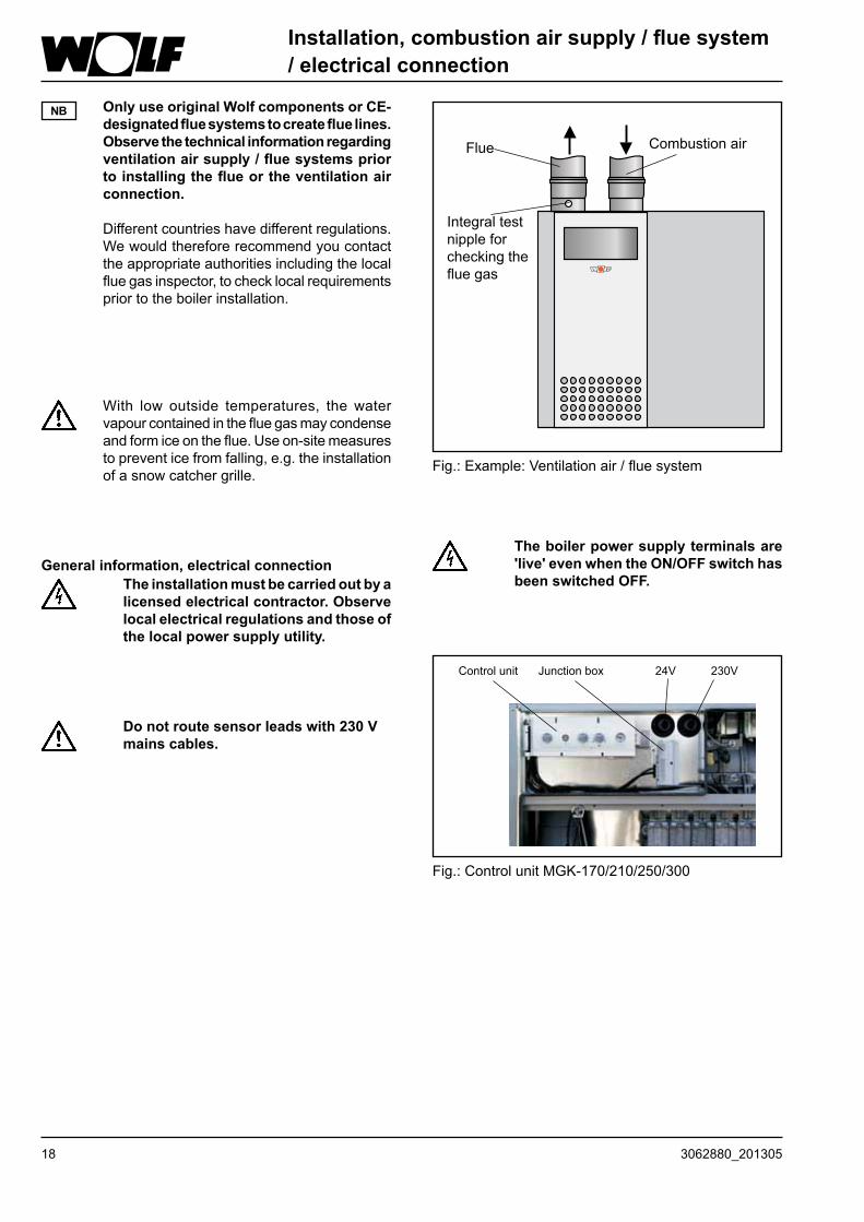
Only use original Wolf components or CE-designated flue systems to create flue lines. Observe the technical information regarding ventilation air supply / flue systems prior to installing the flue or the ventilation air connection.
Differentcountrieshavedifferentregulations.Wewouldthereforerecommendyoucontacttheappropriateauthoritiesincludingthelocalfluegasinspector,tochecklocalrequirementspriortotheboilerinstallation.
NB
With low outside temperatures, thewatervapourcontainedinthefluegasmaycondenseandformiceontheflue.Useon-sitemeasurestopreventicefromfalling,e.g.theinstallationofasnowcatchergrille.
The boiler power supply terminals are 'live' even when the ON/OFF switch has been switched OFF.
General information, electrical connection The installation must be carried out by a
licensed electrical contractor. Observe local electrical regulations and those of the local power supply utility.
Fig.:ControlunitMGK-170/210/250/300
24VControlunit 230VJunctionbox
Do not route sensor leads with 230 V mains cables.
Flue
Fig.:Example:Ventilationair/fluesystem
Combustionair
Integraltestnippleforcheckingthefluegas
193062880_201305
Electrical connection
Installation information, electrical connection, mains
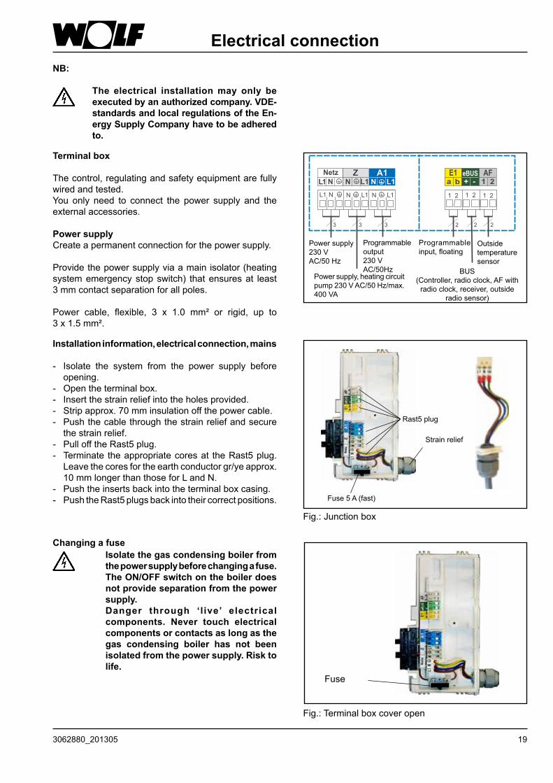
- Isolate the system from the power supply beforeopening.
- Opentheterminalbox.- Insertthestrainreliefintotheholesprovided.- Stripapprox.70mminsulationoffthepowercable.- Pushthecablethroughthestrainreliefandsecurethestrainrelief.
- PullofftheRast5plug.- Terminate theappropriatecoresat theRast5plug.Leavethecoresfortheearthconductorgr/yeapprox.10mmlongerthanthoseforLandN.
- Pushtheinsertsbackintotheterminalboxcasing.- PushtheRast5plugsbackintotheircorrectpositions.
Fig.:Junctionbox
Fuse5A(fast)
Rast5plug
Strainrelief
Terminal box
Thecontrol,regulatingandsafetyequipmentarefullywiredandtested.You only need to connect the power supply and theexternalaccessories.
Power supplyCreateapermanentconnectionforthepowersupply.
Providethepowersupplyviaamainisolator(heatingsystememergencystopswitch) thatensuresat least3mmcontactseparationforallpoles.
Power cable, flexible, 3 x 1.0 mm² or rigid, up to 3x1.5mm².
Powersupply230V AC/50Hz
Powersupply,heatingcircuitpump230VAC/50Hz/max.400VA
Programmableoutput230VAC/50Hz
Programmableinput,floating
Outsidetemperaturesensor
BUS(Controller,radioclock,AFwithradioclock,receiver,outside
radiosensor)
Isolate the gas condensing boiler from the power supply before changing a fuse. The ON/OFF switch on the boiler does not provide separation from the power supply.
Danger through ‘l ive’ electrical components. Never touch electrical components or contacts as long as the gas condensing boiler has not been isolated from the power supply. Risk to life.
Changing a fuse
Fig.:Terminalboxcoveropen
Fuse
NB:
The electrical installation may only be executed by an authorized company. VDE-standards and local regulations of the En-ergy Supply Company have to be adhered to.

20 3062880_201305
Fig.:Connection,heatingcircuitpump
Heating circuit pump connection (230 V AC; max. 400 VA)
Insertthecableglandsintotheterminalbox.Insertandsecurethecablethroughthecableentry.Connecttheheatingcircuitpump230VACtoterminalsL1,Nand .
Electrical connection
Wiring diagram, ventilation air damper (not for MGK-130)
Schaltplan fürZuluftklappeMGK 170-250
1
von 1
AFE1 eBUS+ - 1 2a b
Netz Z A1N
N
NL1L1 L1
o o o o o o
MT3,15 A
F1
1 2 1 21 2L1N L1L1 NN L1N L1N
Supply air damper with servomotor
ElektroanschlußkastenMGK
24VDC
Limit switch
NB:Limit switch for supply air damper must be floating!Otherwise the MGK control unit will be destroyed.
Note:The contractor parameter
(input 1)(factory setting for supply air damper) and
(input 1)(factory setting for supply air damper)
With the contact open, the burner remains blocked for DHW and central heating, even for emissions test and frost protection.
HG13/GB13 must be set to 5
HG14/GB14 must be set to 7
Power supply 230 V AC
brbl
M230V~
51-10-018-045Benennung Zeichnungsnummer
CorelDraw
Art.- / Materialnummer
Blatt
Bl.NameName Ausg.Ausg. ÄnderungÄnderung AntragAntrag DatumDatum
TerminalboxMGK
5 A
213062880_201305
Electrical connection
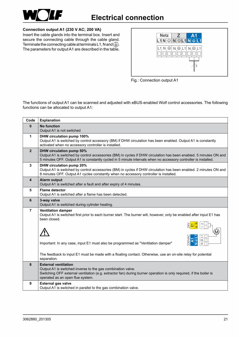
Code Explanation0 No function
OutputA1isnotswitched1 DHW circulation pump 100%
OutputA1isswitchedbycontrolaccessory(BM)ifDHWcirculationhasbeenenabled.OutputA1isconstantlyactivatedwhennoaccessorycontrollerisinstalled.
2 DHW circulation pump 50% OutputA1isswitchedbycontrolaccessories(BM)incyclesifDHWcirculationhasbeenenabled.5minutesONand5minutesOFF.OutputA1isconstantlycycledin5minuteintervalswhennoaccessorycontrollerisinstalled.
3 DHW circulation pump 20% OutputA1isswitchedbycontrolaccessories(BM)incyclesifDHWcirculationhasbeenenabled.2minutesONand8minutesOFF.OutputA1cyclesconstantlywhennoaccessorycontrollerisinstalled.
4 Alarm output OutputA1isswitchedafterafaultandafterexpiryof4minutes.
5 Flame detector OutputA1isswitchedafteraflamehasbeendetected.
6 3-way valve OutputA1isswitchedduringcylinderheating.
7 Ventilation damper OutputA1isswitchedfirstpriortoeachburnerstart.Theburnerwill,however,onlybeenabledafterinputE1hasbeenclosed.
Important:Inanycase,inputE1mustalsobeprogrammedas"Ventilationdamper"
ThefeedbacktoinputE1mustbemadewithafloatingcontact.Otherwise,useanon-siterelayforpotentialseparation.
8 External ventilation OutputA1isswitchedinversetothegascombinationvalve. SwitchingOFFexternalventilation(e.g.extractorfan)duringburneroperationisonlyrequired,iftheboilerisoperatedasanopenfluesystem.
9 External gas valve OutputA1isswitchedinparalleltothegascombinationvalve.
The functionsofoutputA1canbescannedandadjustedwitheBUS-enabledWolfcontrolaccessories.ThefollowingfunctionscanbeallocatedtooutputA1:
Fig.:ConnectionoutputA1
Connection output A1 (230 V AC; 200 VA)Insertthecableglandsintotheterminalbox.Insertandsecuretheconnectingcablethroughthecablegland.TerminatetheconnectingcableatterminalsL1,Nand .TheparametersforoutputA1aredescribedinthetable.
22 3062880_201305
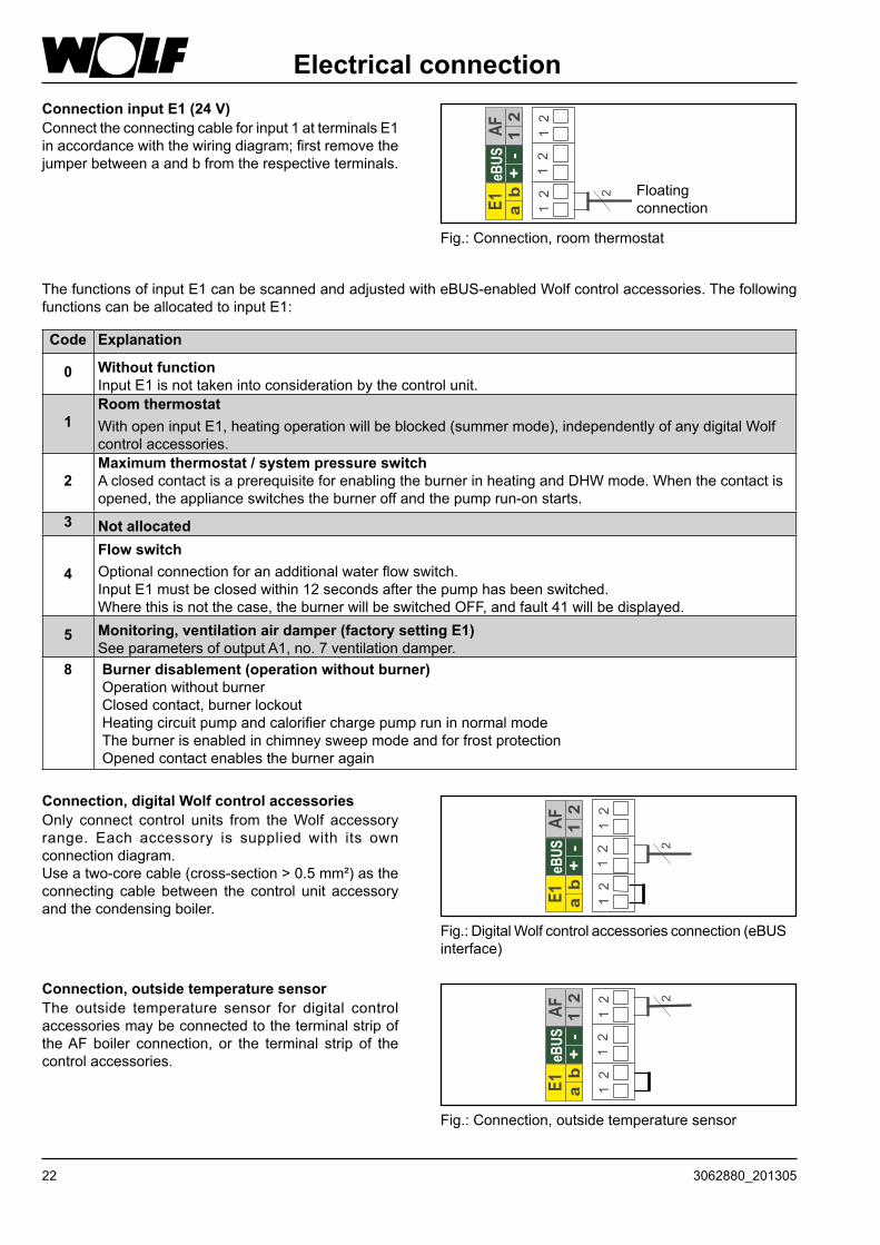
Electrical connectionConnection input E1 (24 V)Connecttheconnectingcableforinput1atterminalsE1inaccordancewiththewiringdiagram;firstremovethejumperbetweenaandbfromtherespectiveterminals.
Fig.:Connection,roomthermostat
Floatingconnection
Code Explanation
0 Without functionInputE1isnottakenintoconsiderationbythecontrolunit.
1Room thermostat WithopeninputE1,heatingoperationwillbeblocked(summermode),independentlyofanydigitalWolfcontrolaccessories.
2Maximum thermostat / system pressure switch AclosedcontactisaprerequisiteforenablingtheburnerinheatingandDHWmode.Whenthecontactisopened,theapplianceswitchestheburneroffandthepumprun-onstarts.
3 Not allocated
4Flow switchOptionalconnectionforanadditionalwaterflowswitch.InputE1mustbeclosedwithin12secondsafterthepumphasbeenswitched.Wherethisisnotthecase,theburnerwillbeswitchedOFF,andfault41willbedisplayed.
5 Monitoring, ventilation air damper (factory setting E1)SeeparametersofoutputA1,no.7ventilationdamper.
8 Burner disablement (operation without burner) Operationwithoutburner Closedcontact,burnerlockout Heatingcircuitpumpandcalorifierchargepumpruninnormalmode Theburnerisenabledinchimneysweepmodeandforfrostprotection Openedcontactenablestheburneragain
The functionsofinputE1canbescannedandadjustedwitheBUS-enabledWolfcontrolaccessories.ThefollowingfunctionscanbeallocatedtoinputE1:
Connection, digital Wolf control accessoriesOnly connect control units from theWolf accessoryrange. Each accessory is supplied with its ownconnectiondiagram.Useatwo-corecable(cross-section>0.5mm²)astheconnecting cable between the control unit accessoryandthecondensingboiler.
Fig.:DigitalWolfcontrolaccessoriesconnection(eBUSinterface)
Connection, outside temperature sensorThe outside temperature sensor for digital controlaccessoriesmaybeconnectedtotheterminalstripoftheAFboiler connection, or the terminal strip of thecontrolaccessories.
Fig.:Connection,outsidetemperaturesensor
233062880_201305
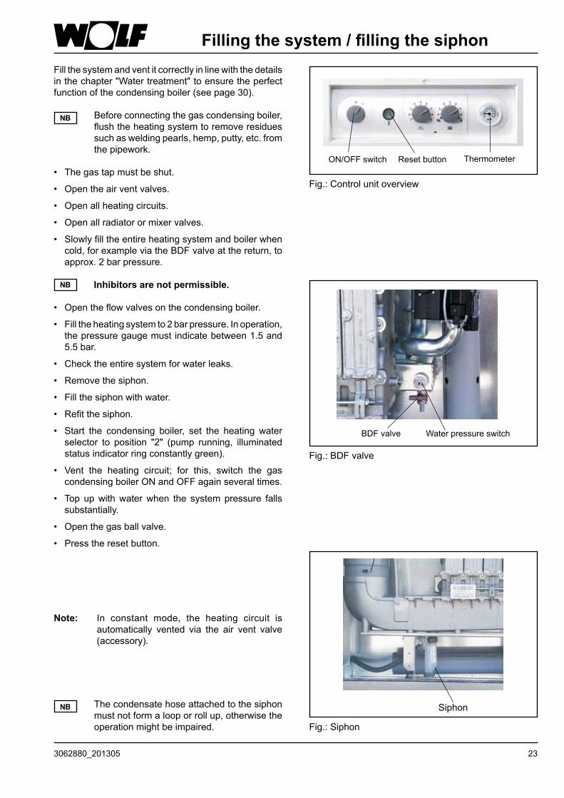
Filling the system / filling the siphonFillthesystemandventitcorrectlyinlinewiththedetailsinthechapter"Watertreatment"toensuretheperfectfunctionofthecondensingboiler(seepage30).
Beforeconnectingthegascondensingboiler,flushtheheatingsystemtoremoveresiduessuchasweldingpearls,hemp,putty,etc.fromthepipework.
• Thegastapmustbeshut.
• Opentheairventvalves.
• Openallheatingcircuits.
• Openallradiatorormixervalves.
• Slowlyfilltheentireheatingsystemandboilerwhencold,forexampleviatheBDFvalveatthereturn,toapprox.2barpressure.
Inhibitors are not permissible.
• Opentheflowvalvesonthecondensingboiler.
• Filltheheatingsystemto2barpressure.Inoperation,thepressuregaugemustindicatebetween1.5and5.5bar.
• Checktheentiresystemforwaterleaks.
• Removethesiphon.
• Fillthesiphonwithwater.
• Refitthesiphon.
• Start the condensing boiler, set the heating waterselector to position "2" (pump running, illuminatedstatusindicatorringconstantlygreen).
• Vent the heating circuit; for this, switch the gascondensingboilerONandOFFagainseveraltimes.
• Top upwithwaterwhen the systempressure fallssubstantially.
• Openthegasballvalve.
• Presstheresetbutton.
NB
NB
Note: In constant mode, the heating circuit isautomatically vented via the air vent valve(accessory).
Fig.:Siphon
Siphon
Fig.:Controlunitoverview
ON/OFFswitch ThermometerResetbutton
Fig.:BDFvalve
BDFvalve Waterpressureswitch
Thecondensatehoseattachedtothesiphonmustnotformalooporrollup,otherwisetheoperationmightbeimpaired.
NB
24 3062880_201305
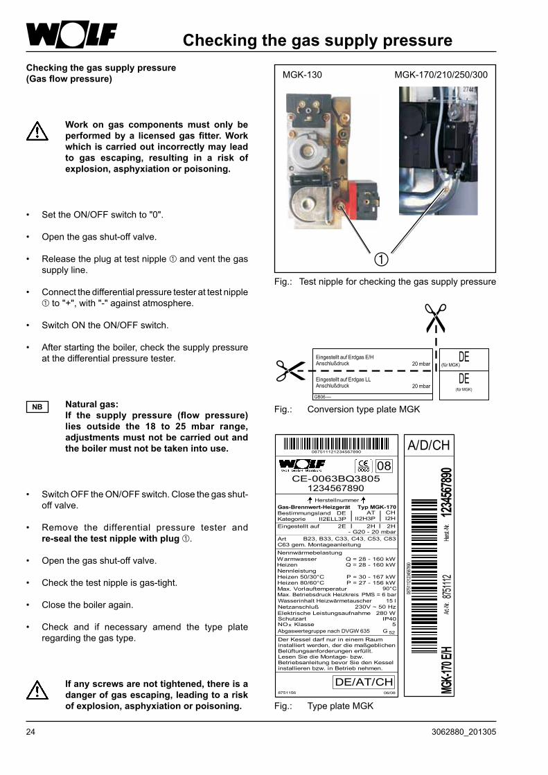
Checking the gas supply pressure (Gas flow pressure)
• SettheON/OFFswitchto"0".
• Openthegasshut-offvalve.
• Releasetheplugattestnippleandventthegassupplyline.
• Connectthedifferentialpressuretesterattestnippleto"+",with"-"againstatmosphere.
• SwitchONtheON/OFFswitch.
• Afterstartingtheboiler,checkthesupplypressureatthedifferentialpressuretester.
Work on gas components must only be performed by a licensed gas fitter. Work which is carried out incorrectly may lead to gas escaping, resulting in a risk of explosion, asphyxiation or poisoning.
Checking the gas supply pressure
• SwitchOFFtheON/OFFswitch.Closethegasshut-off valve.
• Remove the differential pressure tester and re-seal the test nipple with plug .
• Openthegasshut-offvalve.
• Checkthetestnippleisgas-tight.
• Closetheboileragain.
• Check and if necessary amend the type plateregardingthegastype.
Natural gas: If the supply pressure (flow pressure)
lies outside the 18 to 25 mbar range, adjustments must not be carried out and the boiler must not be taken into use.
NB
If any screws are not tightened, there is a danger of gas escaping, leading to a risk of explosion, asphyxiation or poisoning.
Fig.: Testnippleforcheckingthegassupplypressure
MGK-170/210/250/300MGK-130
Gas-Brennwert-Heizgerät
1234567890Herstellnummer
Nennwärmebelastung
HeizenNennleistungHeizen50/30°CHeizen80/60°C
Netzanschluß
Q=28-160kW
P=30-167kWP=27-156kW
90°C
230V~50Hz280 WElektrischeLeistungsaufnahme
Schutzart
Max.VorlauftemperaturMax.BetriebsdruckHeizkreis PMS=6bar
IP40
WasserinhaltHeizwärmetauscher
087511121234567890
0875
1112
1234
5678
90
875111
2Art.-N
r.
CE-0063BQ3805
A/D/CH123
456789
0Herst.
-Nr.
08
Typ MGK-170
NOx Klasse 5
Kategorie
-G20-20mbar
Bestimmungsland
Eingestelltauf
B23,B33,C33,C43,C53,C83C63gem.Montageanleitung
15 l
Warmwasser Q=28-160kW
AbgaswertegruppenachDVGW635 G 52
Art
8751156 06/08
DE/AT/CH
DerKesseldarfnurineinemRauminstalliertwerden,derdiemaßgeblichenBelüftungsanforderungenerfüllt.LesenSiedieMontage-bzw.BetriebsanleitungbevorSiedenKesselinstallierenbzw.inBetriebnehmen.
MGK-1
70 E/H
II2ELL3PDE
II2H3PAT
2H2E
CHI2H2H
Fig.: TypeplateMGK
Fig.: ConversiontypeplateMGK
253062880_201305
Saving energy
• Instruct the customer about energy saving options.
• Refer your customer to section "Information for energy efficient operation" in the operating instructions.
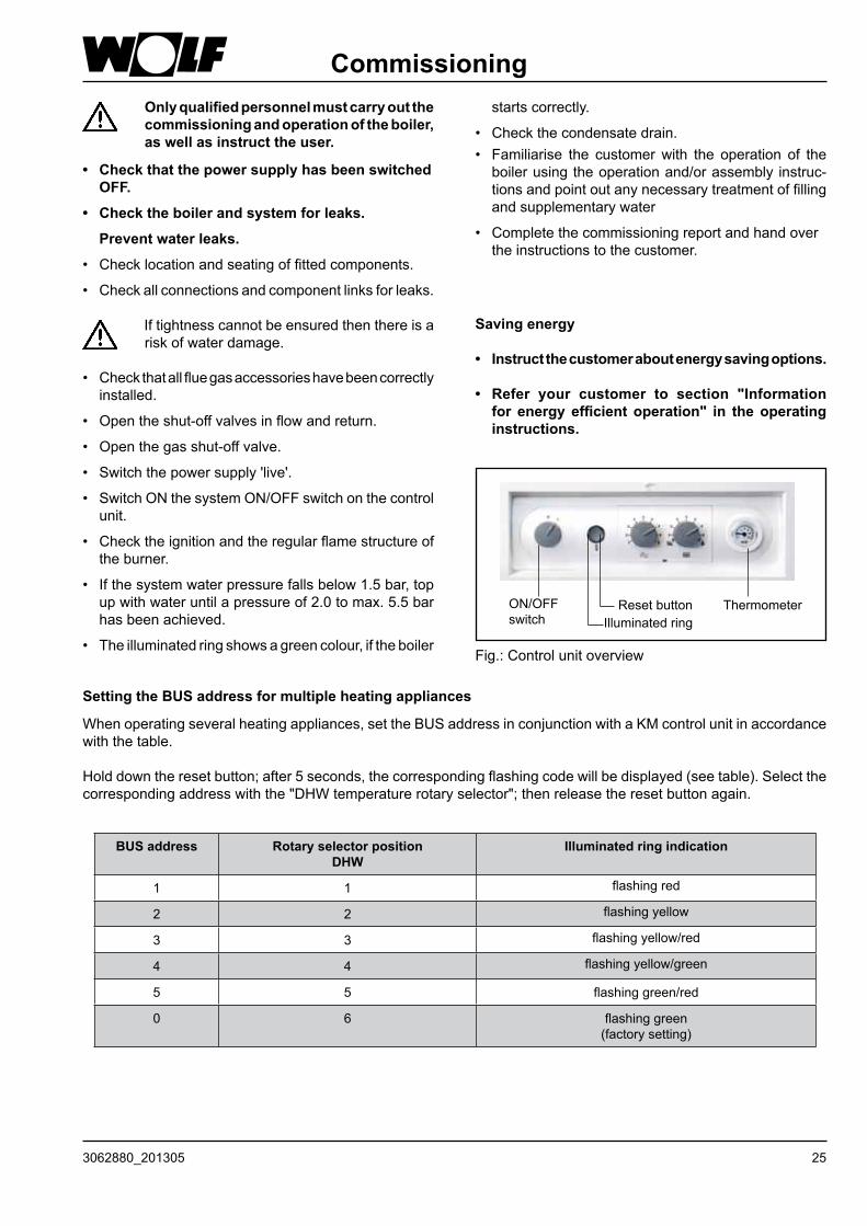
Only qualified personnel must carry out the commissioning and operation of the boiler, as well as instruct the user.
Fig.:Controlunitoverview
ON/OFFswitch
ThermometerResetbuttonIlluminatedring
Commissioning
• Check that the power supply has been switched OFF.
• Check the boiler and system for leaks.
Prevent water leaks.
• Checklocationandseatingoffittedcomponents.
• Checkallconnectionsandcomponentlinksforleaks.
Iftightnesscannotbeensuredthenthereisariskofwaterdamage.
• Checkthatallfluegasaccessorieshavebeencorrectlyinstalled.
• Opentheshut-offvalvesinflowandreturn.
• Openthegasshut-offvalve.
• Switchthepowersupply'live'.
• SwitchONthesystemON/OFFswitchonthecontrolunit.
• Checktheignitionandtheregularflamestructureoftheburner.
• Ifthesystemwaterpressurefallsbelow1.5bar,topupwithwateruntilapressureof2.0tomax.5.5barhasbeenachieved.
• Theilluminatedringshowsagreencolour,iftheboiler
Setting the BUS address for multiple heating appliances
Whenoperatingseveralheatingappliances,settheBUSaddressinconjunctionwithaKMcontrolunitinaccordancewiththetable.
Holddowntheresetbutton;after5seconds,thecorrespondingflashingcodewillbedisplayed(seetable).Selectthecorrespondingaddresswiththe"DHWtemperaturerotaryselector";thenreleasetheresetbuttonagain.
BUS address Rotary selector positionDHW
Illuminated ring indication
1 1 flashingred
2 2 flashingyellow
3 3 flashingyellow/red
4 4 flashingyellow/green
5 5 flashinggreen/red
0 6 flashinggreen (factorysetting)
startscorrectly.
• Checkthecondensatedrain.• Familiarise the customerwith the operation of theboilerusingtheoperationand/orassembly instruc-tionsandpointoutanynecessarytreatmentoffillingandsupplementarywater
• Completethecommissioningreportandhandovertheinstructionstothecustomer.
26 3062880_201305
Displaying / modifying control parameters
Modifications must only be carried out by a recognised heating contractor or by Wolf customer service.
Incorrect operation can lead to system faults.When selecting parameter GB 05 (frost protection, outside temperature) note that frost protection is no longer ensured at temperatures below 0 °C. This can lead to heating system damage.
NB
NB
To prevent damage to the heating system, cancel night setback when outside temperatures fall below −12 °C. If this rule is not observed, ice may build up on the flue outlet which may cause injury or material losses.
You can check the output data for the boiler on the type plate.
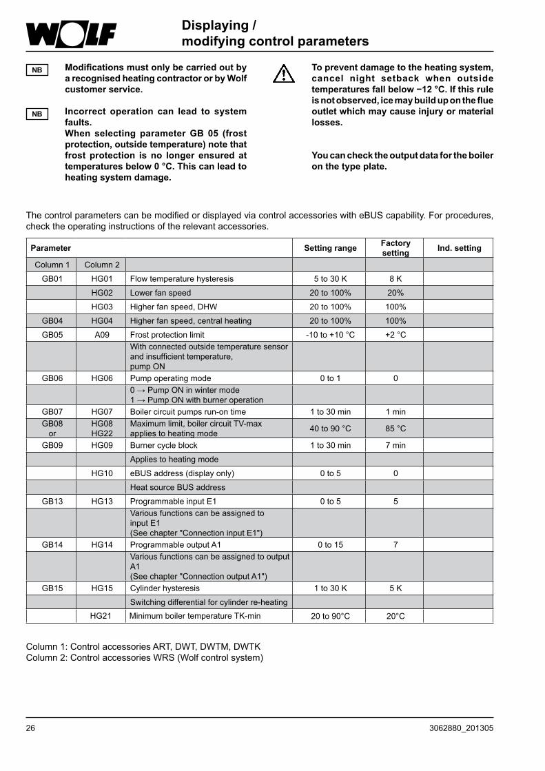
ThecontrolparameterscanbemodifiedordisplayedviacontrolaccessorieswitheBUScapability.Forprocedures,checktheoperatinginstructionsoftherelevantaccessories.
Parameter Setting range Factory setting Ind. setting
Column 1 Column 2
GB01 HG01 Flowtemperaturehysteresis 5 to 30 K 8 K
HG02 Lowerfanspeed 20 to 100% 20%
HG03 Higherfanspeed,DHW 20 to 100% 100%
GB04 HG04 Higherfanspeed,centralheating 20 to 100% 100%
GB05 A09 Frostprotectionlimit -10to+10°C +2°CWithconnectedoutsidetemperaturesensorandinsufficienttemperature, pumpON
GB06 HG06 Pumpoperatingmode 0 to 1 00→PumpONinwintermode1→PumpONwithburneroperation
GB07 HG07 Boilercircuitpumpsrun-ontime 1 to 30 min 1 minGB08or
HG08HG22
Maximumlimit,boilercircuitTV-maxappliestoheatingmode 40to90°C 85°C
GB09 HG09 Burnercycleblock 1 to 30 min 7 min
Appliestoheatingmode
HG10 eBUSaddress(displayonly) 0 to 5 0
HeatsourceBUSaddress
GB13 HG13 ProgrammableinputE1 0 to 5 5Variousfunctionscanbeassignedto input E1(Seechapter"ConnectioninputE1")
GB14 HG14 ProgrammableoutputA1 0 to 15 7VariousfunctionscanbeassignedtooutputA1(Seechapter"ConnectionoutputA1")
GB15 HG15 Cylinderhysteresis 1 to 30 K 5 K
Switchingdifferentialforcylinderre-heatingHG21 MinimumboilertemperatureTK-min 20to90°C 20°C
Column1:ControlaccessoriesART,DWT,DWTM,DWTKColumn2:ControlaccessoriesWRS(Wolfcontrolsystem)
273062880_201305
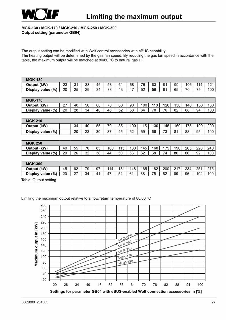
MGK-130 / MGK-170 / MGK-210 / MGK-250 / MGK-300Output setting (parameter GB04)
TheoutputsettingcanbemodifiedwithWolfcontrolaccessorieswitheBUScapability.Theheatingoutputwillbedeterminedbythegasfanspeed.Byreducingthegasfanspeedinaccordancewiththetable,themaximumoutputwillbematchedat80/60°CtonaturalgasH.
Limiting the maximum output
MGK-130Output (kW) 23 31 38 46 53 61 68 76 83 91 99 106 114 121Display value (%) 20 25 29 34 38 43 47 52 56 61 65 70 75 100
MGK-170Output (kW) 27 40 50 60 70 80 90 100 110 120 130 140 150 160Display value (%) 20 28 34 40 46 52 58 64 70 76 82 88 94 100
MGK 210Output (kW) 34 40 55 70 85 100 115 130 145 160 175 190 200Display value (%) 20 23 30 37 45 52 59 66 73 81 88 95 100
MGK 250Output (kW) 40 55 70 85 100 115 130 145 160 175 190 205 220 240Display value (%) 20 26 32 38 44 50 56 62 68 74 80 86 92 100
MGK-300Output (kW) 45 62 79 97 114 131 148 165 182 200 217 234 251 275Display value (%) 20 27 34 41 47 54 61 68 75 82 89 96 102 100
Table:Outputsetting
Limitingthemaximumoutputrelativetoaflow/returntemperatureof80/60°C
Settings for parameter GB04 with eBUS-enabled Wolf connection accessories in [%]
Max
imum
out
put i
n [k
W]
28 3062880_201305
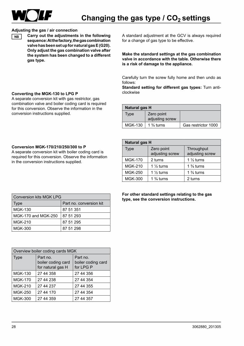
Changing the gas type / CO2 settings Adjusting the gas / air connection Carry out the adjustments in the following
sequence: At the factory, the gas combination valve has been set up for natural gas E (G20). Only adjust the gas combination valve after the system has been changed to a different gas type.
NB
Conversion MGK-170/210/250/300 to PAseparateconversionkitwithboilercodingcardisrequiredforthisconversion.Observetheinformationintheconversioninstructionssupplied.
AstandardadjustmentattheGCVisalwaysrequiredforachangeofgastypetobeeffective.
Make the standard settings at the gas combination valve in accordance with the table. Otherwise there is a risk of damage to the appliance.
Carefullyturnthescrewfullyhomeandthenundoasfollows:Standard setting for different gas types: Turnanti-clockwiseConverting the MGK-130 to LPG P
Aseparateconversionkitwithgasrestrictor,gascombinationvalveandboilercodingcardisrequiredforthisconversion.Observetheinformationintheconversioninstructionssupplied.
Natural gas HType Zeropoint
adjustingscrewMGK-130 1¾turns Gasrestrictor1000
ConversionkitsMGKLPGType Partno.conversionkitMGK-130 87 51 351MGK-170 and MGK-250 87 51 293MGK-210 87 51 295MGK-300 87 51 298
OverviewboilercodingcardsMGKType Partno.
boilercodingcardfornaturalgasH
Partno. boilercodingcardforLPGP
MGK-130 27 44 358 27 44 356MGK-170 27 44 238 27 44 354MGK-210 27 44 237 27 44 355MGK-250 27 44 170 27 44 354MGK-300 27 44 359 27 44 357
For other standard settings relating to the gas type, see the conversion instructions.
Natural gas HType Zeropoint
adjustingscrewThroughputadjustingscrew
MGK-170 2turns 1½turnsMGK-210 1½turns 1¾turnsMGK-250 1½turns 1¾turnsMGK-300 1¾turns 2turns

293062880_201305
B) CO2 adjustment at the lower load (soft start)
• Restart the gas condensing boiler by pressing the"Resetbutton".
• Check and if necessary correct the CO2 content approx.30safterburnerstartusingtheCO2tester,byfineadjustingthezero point adjusting screw in accordancewiththetable.Makethisadjustmentwithin120softheburnerstart.Ifnecessary,repeatthestartphase for setting procedures by pressing the resetbutton.
•Turn clockwise - raises CO2 content•Turn anti-clockwise - lowers CO2 content
Appliance open(withoutcasing)atlower loadNaturalgasH9.0% ± 0.2%
Changing the gas type / CO2 settingsA) CO2 setting at the upper load (emissions test mode)
• Undothefourscrewsfromthefrontcasingandremovethecasing.
• Removethescrewfromthe"fluegas"testport.
• InsertthetestprobeoftheCO2testinstrumentintothe"fluegas"testport.
• Turnthetemperatureselectorto "Emissionstest" . (Illuminatedstatusindicatorringflashesyellow.)
• ChecktheCO2contentatfullload,andcomparetheactualvalueswiththoseinthetablebelow.
• CorrecttheCO2settingasrequiredusingthegas throughput adjusting screwonthegascombinationvalveinaccordancewiththetable.
• Turn clockwise - lowers CO2 content• Turn anti-clockwise - raises CO2 content
• Terminatetheemissionstestmodebyreturningthetemperatureselectortoitsoriginalposition.
Fig.:Fluegastestattheintegraltestport
Testport,fluegas
Fig.:Gascombinationvalve
Gasthroughputadjustingscrew(undercover)Allenscrew3mmfortheMGK-170-MGK-300)SlottedscrewfortheMGK-130
MGK-170/210/250/300MGK-130
Appliance open(withoutcasing)atupper loadNaturalgasH9.2% ± 0.2%
Fig.:Gascombinationvalve
Zeropointadjustingscrew,Tx40Torx(underthecover)
MGK-170/210/250/300MGK-130
30 3062880_201305
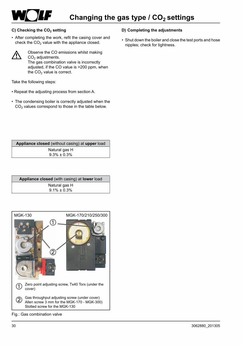
Changing the gas type / CO2 settingsD) Completing the adjustments
• Shutdowntheboilerandclosethetestportsandhosenipples;checkfortightness.
C) Checking the CO2 setting
• Aftercompletingthework,refitthecasingcoverandchecktheCO2valuewiththeapplianceclosed.
ObservetheCOemissionswhilstmakingCO2adjustments. Thegascombinationvalveisincorrectlyadjusted,iftheCOvalueis>200ppm,whentheCO2valueiscorrect.
Takethefollowingsteps:
•RepeattheadjustingprocessfromsectionA.
• ThecondensingboileriscorrectlyadjustedwhentheCO2valuescorrespondtothoseinthetablebelow.
Appliance closed(withoutcasing)atupper loadNaturalgasH9.3% ± 0.3%
Appliance closed(withcasing)atlower loadNaturalgasH9.1% ± 0.3%
Fig.:Gascombinationvalve
MGK-170/210/250/300MGK-130
Zeropointadjustingscrew,Tx40Torx(underthecover)
Gasthroughputadjustingscrew(undercover)Allenscrew3mmfortheMGK-170-MGK-300)SlottedscrewfortheMGK-130

313062880_201305
Testing the combustion parametersTestthecombustionparameterswiththeboilerclosed!
Testing the flue gas parameters
Flue gas can escape into the installation room, if the test port is left open. This results in a risk of asphyxiation.
- Removethescrewfromthe"fluegastestport".- Startthegascondensingboilerandturnthetemperatureselectortotheemissionstestsymbol[chimneysweep]. (Theindicatorringflashesyellow.)
- Insertthetestprobe.- Readofffluegasvaluesandentertheminthecommissioningreport.- Afterthetesthasbeencompleted,removethetestprobeandclosethetestportagain.Ensurethescrewsareseatedfirmly.
- Returnthetemperatureselectorintoitsoriginalposition.
Testing the combustion air
- Holdthetestprobeintothecombustionairsupplyandcalibratethetesteror
- forbalancedflueoperation,insertthetestprobeintotheventilationairadaptor.
Startthegascondensingboilerandturntheheatingwater temperatureselectortotheemissionstestsymbol.
(Thestatusdisplayringflashesyellow.) -Checkthetemperatureandenteritinthecommissioningreport. -Afterthetesthasbeencompleted,switchtheboilerOFF,remove thetestprobeandclosethetestport.Ensurethescrewsare seatedfirmly. -Returnthetemperatureselectorintoitsoriginalposition.
ON/OFFswitch Temperatureselector
"Inletair"testport
Testport, fluegas
32 3062880_201305
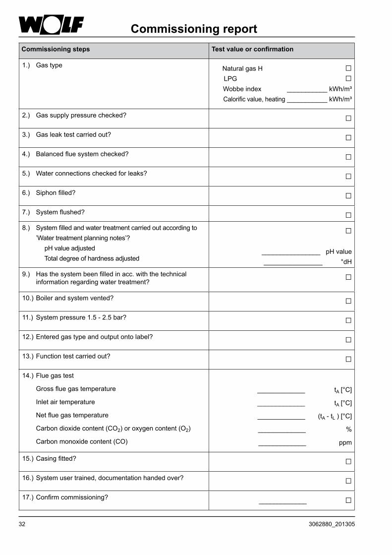
Commissioning reportCommissioning steps Test value or confirmation
1.) Gastype NaturalgasH□LPG□Wobbeindex___________kWh/m³Calorificvalue,heating___________kWh/m³
2.) Gassupplypressurechecked? □3.) Gasleaktestcarriedout? □4.) Balancedfluesystemchecked? □5.) Waterconnectionscheckedforleaks? □6.) Siphonfilled? □7.) Systemflushed? □8.) Systemfilledandwatertreatmentcarriedoutaccordingto
’Watertreatmentplanningnotes’? pHvalueadjusted Totaldegreeofhardnessadjusted
□
________________pHvalue ________________°dH
9.) Hasthesystembeenfilledinacc.withthetechnicalinformationregardingwatertreatment?
□
10.)Boilerandsystemvented? □11.) Systempressure1.5-2.5bar? □12.)Enteredgastypeandoutputontolabel? □13.)Functiontestcarriedout? □14.)Fluegastest
Grossfluegastemperature
Inletairtemperature
Netfluegastemperature
Carbondioxidecontent(CO2)oroxygencontent(O2)
Carbonmonoxidecontent(CO)
_____________ tA[°C]
_____________ tA[°C]
_____________(tA - tL)[°C]
_____________ %
_____________ ppm
15.)Casingfitted? □16.)Systemusertrained,documentationhandedover? □17.)Confirmcommissioning? _____________ □
333062880_201305
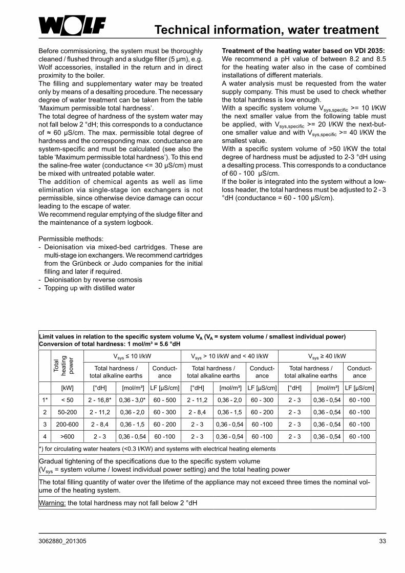
Technical information, water treatmentBeforecommissioning,thesystemmustbethoroughlycleaned/flushedthroughandasludgefilter(5μm),e.g.Wolfaccessories, installed in the returnand indirectproximitytotheboiler.The filling and supplementarywatermay be treatedonlybymeansofadesaltingprocedure.Thenecessarydegreeofwatertreatmentcanbetakenfromthetable‘Maximumpermissibletotalhardness’.Thetotaldegreeofhardnessofthesystemwatermaynotfallbelow2°dH;thiscorrespondstoaconductanceof ≈60μS/cm.Themax.permissible total degreeofhardnessandthecorrespondingmax.conductancearesystem-specificandmustbecalculated(seealso thetable‘Maximumpermissibletotalhardness’).Tothisendthesaline-freewater(conductance<=30μS/cm)mustbemixedwithuntreatedpotablewater.The addition of chemical agents as well as limeelimination via single-stage ion exchangers is notpermissible,sinceotherwisedevicedamagecanoccurleadingtotheescapeofwater.Werecommendregularemptyingofthesludgefilterandthemaintenanceofasystemlogbook.
Permissiblemethods:- Deionisation viamixed-bed cartridges.These aremulti-stageionexchangers.WerecommendcartridgesfromtheGrünbeckorJudocompaniesfortheinitialfillingandlaterifrequired.
- Deionisationbyreverseosmosis- Toppingupwithdistilledwater
Limit values in relation to the specific system volume VA (VA = system volume / smallest individual power)Conversion of total hardness: 1 mol/m³ = 5.6 °dH
Tota
l heating
power
Vsys≤10l/kW Vsys>10l/kWand<40l/kW Vsys≥40l/kW
Totalhardness/ totalalkalineearths
Conduct-ance
Totalhardness/ totalalkalineearths
Conduct-ance
Totalhardness/ totalalkalineearths
Conduct-ance
[kW] [°dH] [mol/m³] LF[μS/cm] [°dH] [mol/m³] LF[μS/cm] [°dH] [mol/m³] LF[μS/cm]
1* < 50 2-16,8* 0,36-3,0* 60 - 500 2-11,2 0,36-2,0 60 - 300 2 - 3 0,36-0,54 60 -100
2 50-200 2-11,2 0,36-2,0 60 - 300 2-8,4 0,36-1,5 60 - 200 2 - 3 0,36-0,54 60 -100
3 200-600 2-8,4 0,36-1,5 60 - 200 2 - 3 0,36-0,54 60 -100 2 - 3 0,36-0,54 60 -100
4 >600 2 - 3 0,36-0,54 60 -100 2 - 3 0,36-0,54 60 -100 2 - 3 0,36-0,54 60 -100
*)forcirculatingwaterheaters(<0.3l/KW)andsystemswithelectricalheatingelements
Gradualtighteningofthespecificationsduetothespecificsystemvolume (Vsys=systemvolume/lowestindividualpowersetting)andthetotalheatingpower
Thetotalfillingquantityofwateroverthelifetimeoftheappliancemaynotexceedthreetimesthenominalvol-umeoftheheatingsystem.
Warning:thetotalhardnessmaynotfallbelow2°dH
Treatment of the heating water based on VDI 2035:We recommenda pH value of between 8.2 and 8.5for the heatingwater also in the case of combinedinstallationsofdifferentmaterials.Awater analysismust be requested from thewatersupplycompany.Thismustbeusedtocheckwhetherthetotalhardnessislowenough.WithaspecificsystemvolumeVsys,specific>=10 l/KWthe next smaller value from the following tablemustbe applied,withVsys,specific >= 20 l/KW the next-but-onesmallervalueandwithVsys,specific>=40 l/KWthesmallestvalue.With a specific systemvolumeof >50 l/KW the totaldegreeofhardnessmustbeadjustedto2-3°dHusingadesaltingprocess.Thiscorrespondstoaconductanceof60-100μS/cm.Iftheboilerisintegratedintothesystemwithoutalow-lossheader,thetotalhardnessmustbeadjustedto2-3°dH(conductance=60-100μS/cm).
34 3062880_201305
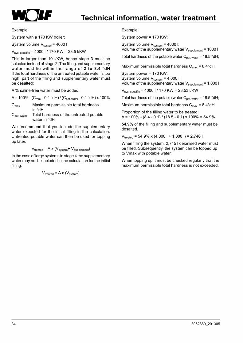
Technical information, water treatmentExample:
Systempower=170KW;
SystemvolumeVsystem=4000l; VolumeofthesupplementarywaterVsupplement = 1000 l
TotalhardnessofthepotablewaterCpot.water=18.5°dH; MaximumpermissibletotalhardnessCmax=8.4°dH
Systempower=170KW; SystemvolumeVsystem=4,000l; VolumeofthesupplementarywaterVsupplement=1,000l
Vsys,specific=4000l/170KW=23.53l/KW
TotalhardnessofthepotablewaterCpot.water=18.5°dH;
MaximumpermissibletotalhardnessCmax=8.4°dH
Proportionofthefillingwatertobetreated: A=100%-(8.4-0.1)/(18.5-0.1)x100%=54.9%
54.9%ofthefillingandsupplementarywatermustbedesalted.
Vtreated=54.9%x(4,000l+1,000l)=2,746l
Whenfillingthesystem,2,745ldeionisedwatermustbefilled.Subsequently,thesystemcanbetoppeduptoVmaxwithpotablewater.
Whentoppingupitmustbecheckedregularlythatthemaximumpermissibletotalhardnessisnotexceeded.
Example:
Systemwitha170KWboiler;
SystemvolumeVsystem= 4000 l
Vsys,specific=4000l/170KW=23.5l/KW
This is larger than 10 l/KW, hence stage 3must beselectedinsteadofstage2.Thefillingandsupplementarywater must lie within the range of 2 to 8.4 °dH Ifthetotalhardnessoftheuntreatedpotablewateristoohigh,partofthefillingandsupplementarywatermustbedesalted:
A%saline-freewatermustbeadded:
A=100%-(Cmax-0,1°dH)/(Cpot.water-0.1°dH)x100%
Cmax Maximumpermissibletotalhardness in°dH Cpot.water Totalhardnessoftheuntreatedpotable waterin°dH
We recommend that you include the supplementarywater expected for the initial filling in the calculation.Untreatedpotablewatercanthenbeusedfortoppinguplater.
Vtreated=Ax(Vsystem+Vsupplement)
Inthecaseoflargesystemsinstage4thesupplementarywatermaynotbeincludedinthecalculationfortheinitialfilling.
Vtreated=Ax(Vsystem)
353062880_201305
System log
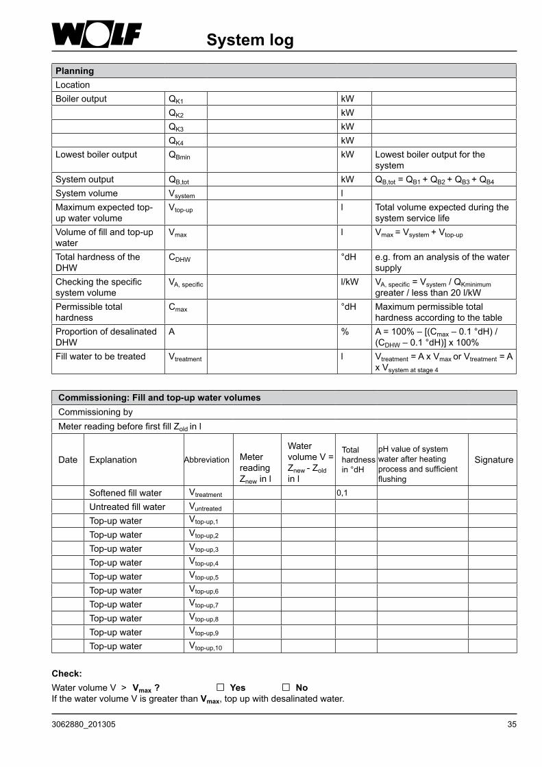
PlanningLocationBoileroutput QK1 kW
QK2 kWQK3 kWQK4 kW
Lowestboileroutput QBmin kW Lowestboileroutputforthesystem
Systemoutput QB,tot kW QB,tot=QB1 +QB2 +QB3 +QB4
Systemvolume Vsystem lMaximumexpectedtop-upwatervolume
Vtop-up l Totalvolumeexpectedduringthesystemservicelife
Volumeoffillandtop-upwater
Vmax l Vmax=Vsystem+Vtop-up
TotalhardnessoftheDHW
CDHW °dH e.g.fromananalysisofthewatersupply
Checkingthespecificsystemvolume
VA,specific l/kW VA,specific=Vsystem/QKminimum greater/lessthan20l/kW
Permissibletotalhardness
Cmax °dH Maximumpermissibletotalhardnessaccordingtothetable
ProportionofdesalinatedDHW
A % A=100%–[(Cmax–0.1°dH)/(CDHW–0.1°dH)]x100%
Fillwatertobetreated Vtreatment l Vtreatment=AxVmaxorVtreatment = A xVsystematstage4
Check: WatervolumeV> Vmax ? □ Yes □ NoIfthewatervolumeVisgreaterthanVmax,topupwithdesalinatedwater.
Commissioning: Fill and top-up water volumesCommissioningbyMeterreadingbeforefirstfillZold in l
Date Explanation Abbreviation Meterreading Znew in l
WatervolumeV=Znew- Zold in l
Total hardnessin°dH
pHvalueofsystemwaterafterheatingprocessandsufficientflushing
Signature
Softenedfillwater Vtreatment 0,1
Untreatedfillwater VuntreatedTop-upwater Vtop-up,1
Top-upwater Vtop-up,2
Top-upwater Vtop-up,3
Top-upwater Vtop-up,4
Top-upwater Vtop-up,5
Top-upwater Vtop-up,6
Top-upwater Vtop-up,7
Top-upwater Vtop-up,8
Top-upwater Vtop-up,9
Top-upwater Vtop-up,10
36 3062880_201305
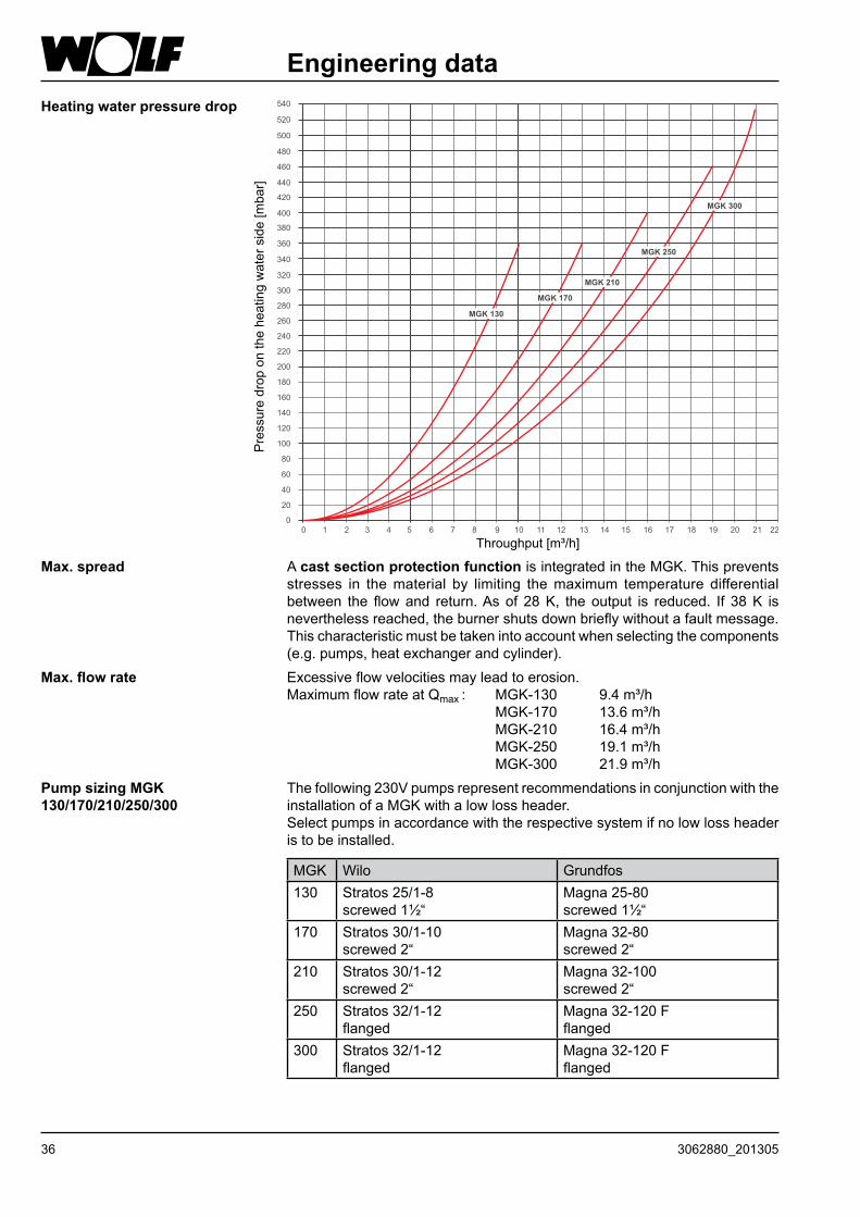
Engineering data
Max. spread A cast section protection functionisintegratedintheMGK.Thispreventsstresses in thematerial by limiting themaximum temperature differentialbetween the flowand return.Asof 28K, theoutput is reduced. If 38K isneverthelessreached,theburnershutsdownbrieflywithoutafaultmessage.Thischaracteristicmustbetakenintoaccountwhenselectingthecomponents(e.g.pumps,heatexchangerandcylinder).
Max. flow rate Excessiveflowvelocitiesmayleadtoerosion.MaximumflowrateatQmax: MGK-130 9.4m³/h MGK-170 13.6m³/h MGK-210 16.4m³/h MGK-250 19.1m³/h MGK-300 21.9m³/h
Heating water pressure drop
Pressuredropontheheatingwaterside[mbar]
Throughput[m³/h]
Pump sizing MGK 130/170/210/250/300
Thefollowing230VpumpsrepresentrecommendationsinconjunctionwiththeinstallationofaMGKwithalowlossheader.Selectpumpsinaccordancewiththerespectivesystemifnolowlossheaderistobeinstalled.
MGK Wilo Grundfos130 Stratos25/1-8
screwed1½“Magna25-80screwed1½“
170 Stratos30/1-10screwed2“
Magna32-80screwed2“
210 Stratos30/1-12screwed2“
Magna32-100screwed2“
250 Stratos32/1-12flanged
Magna32-120Fflanged
300 Stratos32/1-12flanged
Magna32-120Fflanged
373062880_201305
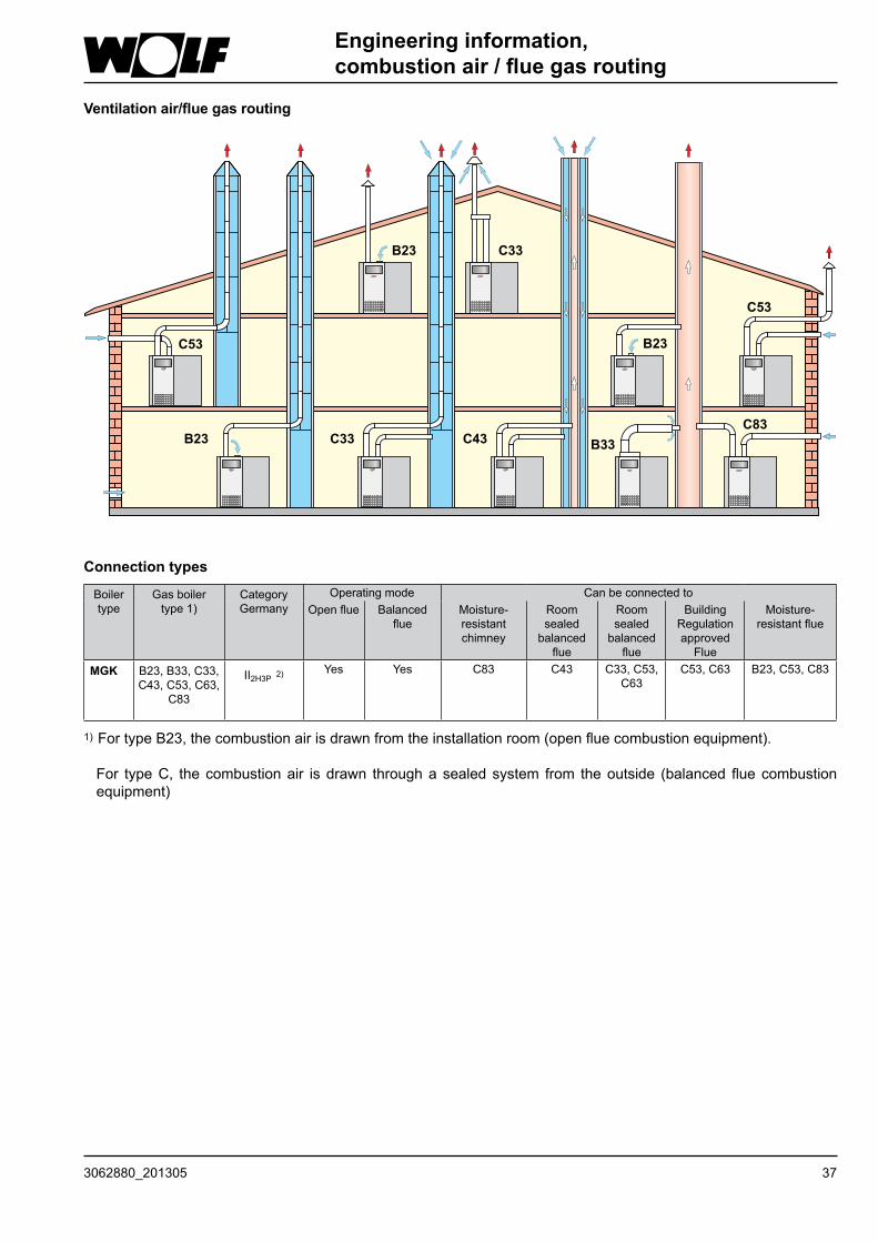
Ventilation air/flue gas routing
Engineering information, combustion air / flue gas routing
1) FortypeB23,thecombustionairisdrawnfromtheinstallationroom(openfluecombustionequipment).
For typeC, thecombustionair isdrawn throughasealedsystem from theoutside (balancedfluecombustionequipment)
Connection types
Boilertype
Gasboiler type1)
CategoryGermany
Operatingmode Can be connected toOpenflue Balanced
flueMoisture-resistantchimney
Room sealed
balancedflue
Room sealed
balancedflue
BuildingRegulationapprovedFlue
Moisture-resistantflue
MGK B23,B33,C33,C43,C53,C63,
C83
II2H3P 2)
Yes Yes C83 C43 C33,C53,C63
C53,C63 B23,C53,C83
38 3062880_201305
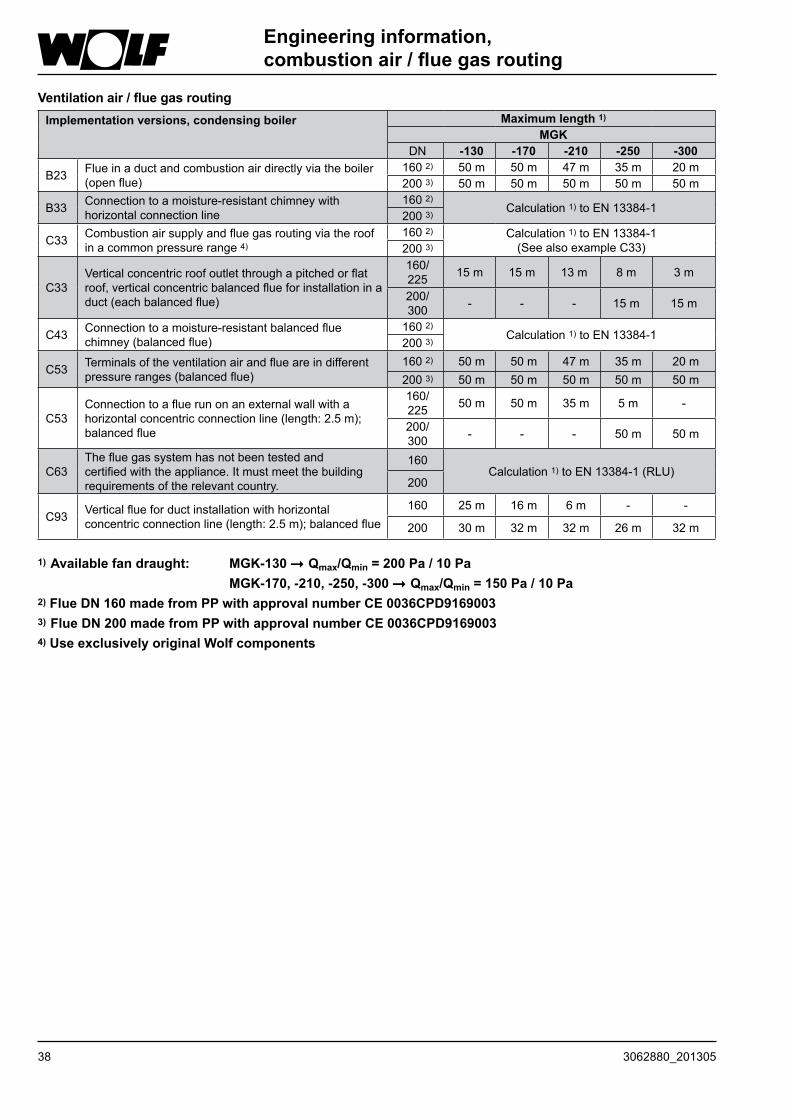
1) Available fan draught: MGK-130 Qmax/Qmin = 200 Pa / 10 Pa MGK-170, -210, -250, -300 Qmax/Qmin = 150 Pa / 10 Pa
2) Flue DN 160 made from PP with approval number CE 0036CPD91690033) Flue DN 200 made from PP with approval number CE 0036CPD91690034) Use exclusively original Wolf components
Ventilation air / flue gas routingImplementation versions, condensing boiler Maximum length 1)
MGKDN -130 -170 -210 -250 -300
B23 Flueinaductandcombustionairdirectlyviatheboiler(openflue)
160 2) 50 m 50 m 47 m 35 m 20 m200 3) 50 m 50 m 50 m 50 m 50 m
B33 Connectiontoamoisture-resistantchimneywithhorizontalconnectionline
160 2)Calculation 1) to EN 13384-1
200 3)
C33 Combustionairsupplyandfluegasroutingviatheroofinacommonpressurerange4)
160 2) Calculation 1) to EN 13384-1(SeealsoexampleC33)200 3)
C33Verticalconcentricroofoutletthroughapitchedorflatroof,verticalconcentricbalancedflueforinstallationinaduct(eachbalancedflue)
160/225 15 m 15 m 13 m 8 m 3 m
200/300 - - - 15 m 15 m
C43 Connectiontoamoisture-resistantbalancedfluechimney(balancedflue)
160 2)Calculation 1) to EN 13384-1
200 3)
C53 Terminalsoftheventilationairandflueareindifferentpressureranges(balancedflue)
160 2) 50 m 50 m 47 m 35 m 20 m200 3) 50 m 50 m 50 m 50 m 50 m
C53Connectiontoafluerunonanexternalwallwithahorizontalconcentricconnectionline(length:2.5m);balancedflue
160/225 50 m 50 m 35 m 5 m -
200/300 - - - 50 m 50 m
C63Thefluegassystemhasnotbeentestedandcertifiedwiththeappliance.Itmustmeetthebuildingrequirementsoftherelevantcountry.
160Calculation 1)toEN13384-1(RLU)
200
C93 Verticalflueforductinstallationwithhorizontalconcentricconnectionline(length:2.5m);balancedflue
160 25 m 16 m 6 m - -
200 30 m 32 m 32 m 26 m 32 m
Engineering information, combustion air / flue gas routing
393062880_201305
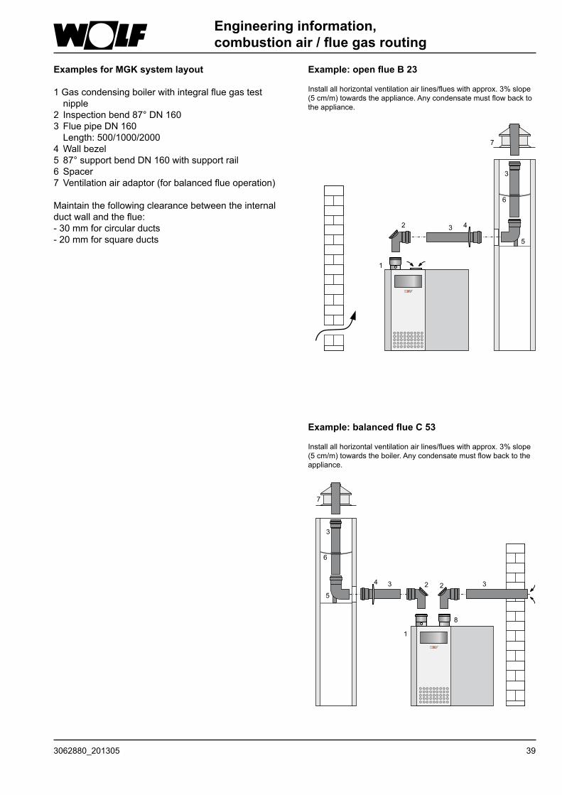
Engineering information, combustion air / flue gas routing
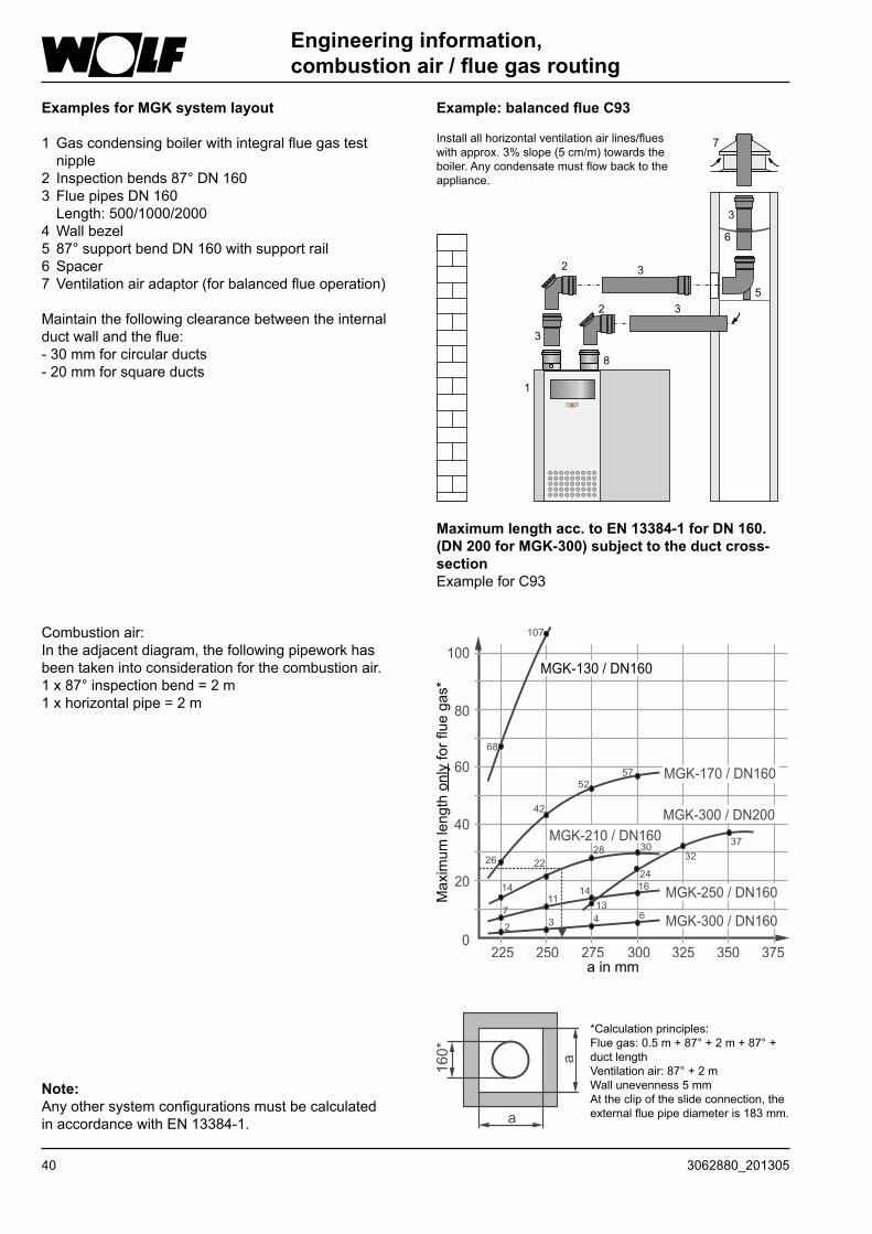
Examples for MGK system layout
1Gascondensingboilerwithintegralfluegastestnipple
2 Inspectionbend87°DN1603 FluepipeDN160 Length:500/1000/20004Wallbezel5 87°supportbendDN160withsupportrail6 Spacer7 Ventilationairadaptor(forbalancedflueoperation)
Maintainthefollowingclearancebetweentheinternalductwallandtheflue:-30mmforcircularducts-20mmforsquareducts
Example: open flue B 23
Installallhorizontalventilationairlines/flueswithapprox.3%slope(5cm/m)towardstheappliance.Anycondensatemustflowbacktothe appliance.
Example: balanced flue C 53
Installallhorizontalventilationairlines/flueswithapprox.3%slope(5cm/m)towardstheboiler.Anycondensatemustflowbacktotheappliance.
40 3062880_201305
Note:AnyothersystemconfigurationsmustbecalculatedinaccordancewithEN13384-1.
*Calculationprinciples:Fluegas:0.5m+87°+2m+87°+ductlengthVentilationair:87°+2mWallunevenness5mmAttheclipoftheslideconnection,theexternalfluepipediameteris183mm.
Engineering information, combustion air / flue gas routing
a in mm
Maximum
lengtho
nlyforfluegas*
Combustionair:Intheadjacentdiagram,thefollowingpipeworkhasbeentakenintoconsiderationforthecombustionair.1x87°inspectionbend=2m1xhorizontalpipe=2m
Examples for MGK system layout
1Gascondensingboilerwithintegralfluegastestnipple
2 Inspectionbends87°DN1603 FluepipesDN160 Length:500/1000/20004Wallbezel5 87°supportbendDN160withsupportrail6 Spacer7 Ventilationairadaptor(forbalancedflueoperation)
Maintainthefollowingclearancebetweentheinternalductwallandtheflue:-30mmforcircularducts-20mmforsquareducts
Example: balanced flue C93
Maximum length acc. to EN 13384-1 for DN 160.(DN 200 for MGK-300) subject to the duct cross-sectionExampleforC93
Installallhorizontalventilationairlines/flueswithapprox.3%slope(5cm/m)towardstheboiler.Anycondensatemustflowbacktotheappliance.
413062880_201305
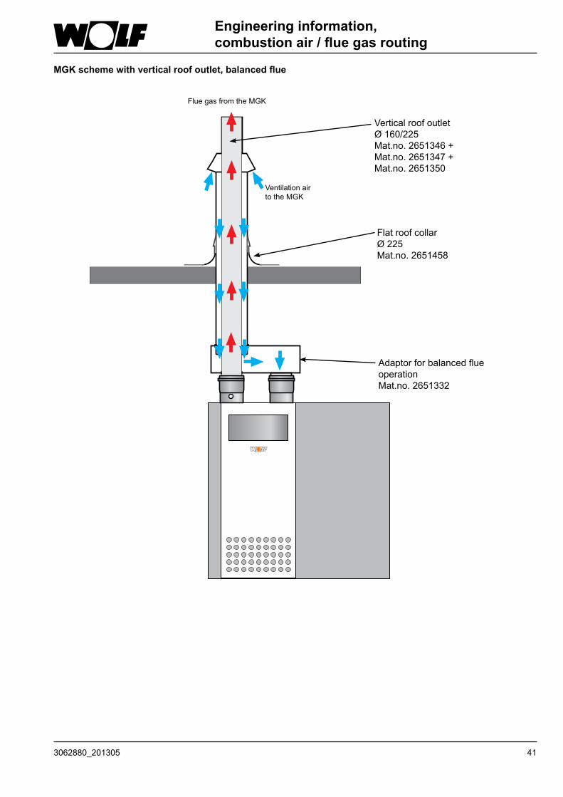
MGK scheme with vertical roof outlet, balanced flue
Verticalroofoutlet Ø160/225Mat.no.2651346+Mat.no.2651347+Mat.no. 2651350
Flatroofcollar Ø 225Mat.no. 2651458
AdaptorforbalancedflueoperationMat.no. 2651332
FluegasfromtheMGK
Ventilationairto the MGK
Engineering information, combustion air / flue gas routing
42 3062880_201305
Engineering information, combustion air / flue gas routing
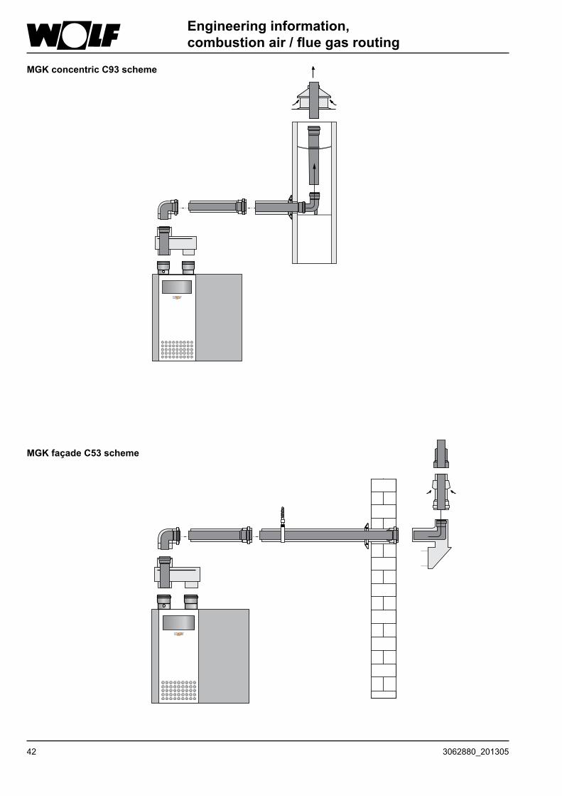
MGK concentric C93 scheme
MGK façade C53 scheme

433062880_201305
With low outside temperatures, the watervapourcontainedinthefluegasmaycondenseand freeze on the balanced flue. This ice may fall from the roof causing injuries or material losses. Use on-site measures topreventicefromfalling,e.g.theinstallationofasnowguard.
Securethebalancedflueorfluethatisoutsideductswith spacer bracketswith aminimumclearance of 50 cm from the flue outlet orupstream/downstreamofdiverterstopreventthepipejointsbeingpulledapart.Ifthisisnotdone,thereisadangerofpoisoningcausedbyescapingfluegas.Furthermore,boilerdamagemayresult.
General information
Wherenecessary,adapttheinstallationexamplestotherelevantBuildingRegulationsandrequirementsofyourcountry/region.Discussanyquestions relating to theinstallationofinspectioncoversandventilationapertureswithyourlocalfluegasinspector.
Flues inside chimney ductsmust have secondaryventilationalongtheirentirelengthandmustterminateabovetheroof.
Fluegascascadesmustbesized inaccordancewithEN 13384-1.
The requirements for installation roomsare specifiedin Building Regulations or Combustion EquipmentOrdinances of the relevant countries. Observe alllocal regulations regarding the room ventilation.
Flues must not be routed through other installation rooms without ducts, otherwise there would be a risk of the transfer of fire and there would be no mechanical protection.
OriginalWolfcomponentshavebeenoptimisedovermanyyearsandarematchedtotheusewithWolfcondensingboilers.WhenusingthirdpartyequipmentthatisonlyCE-designated,theinstallerwillberesponsibleforthecorrectsizingandperfectfunctionofsuchsystems.Faults,materiallossesandinjuriesresultingfromincorrectpipelengths,excessivepressuredrop,prematurewearwithescapingfluegasandcondensateorincorrectfunction,e.g.throughcomponentsworkingthemselvesloose,areexcluded fromourwarranty if non-CE-approved thirdpartyequipmentisused.
If the combustion air is taken from a duct the coonduit has to be free of contaminations!
NB
Connection to a combustion air and flue system type C63 that has not been tested together with the gas combustion equipment.
Theunobstructedcross-sectionoffluesmustbeabletobe inspected.Therefore, install an inspectionand/ortestapertureinsidetheboilerroom;agreesuitablearrangementswithyourlocalfluegasinspector.
Flue connections are created using couplings andgaskets.Alwaysarrangecouplingsagainstthedirectionofthecondensateflow.
Install the ventilation air system / flue with a slope of at least 3° towards the gas condensing boiler. Spacer brackets should be fitted to secure the equipment in position.In the worst case scenario, a lesser slope of the balanced flue may lead to corrosion or operating faults.
Connection to the ventilation air system and the flue
Generally bevel or deburr trimmed flues toensureagas tight installationofpipe joints.Ensure that gaskets are correctly fitted.Removeallcontaminationpriortoinstallation-neverfitdamagedparts.
NB
To prevent flue gas escaping, a positivepressurefluecascadeisonlypermittedwithatestedfluegasdamper(partno.2482896).
FortheMGK-130,thisisalreadyintegrated.
WhensizingfluegassystemsinaccordancewithEN13384-1,maintainamaximumbackpressureofupto130Paintoheaderline;thisshouldalsonotbeexceeded.
NB
Keepthedoorofthecondensingboilershutduringthebuildingphase.Aftercompletingthebuildingphase,removethefilter.
NB
Asprotectionagainstcontaminationduringthebuildingphase,werecommendtheuseofthecompleteventilationairfilter forMGK-130 to300(partno.9751390).Theventilationairfilterispluggedintotheairintake.
Engineering information, combustion air / flue gas routing
Thecombustionairmustnotbedrawnfromchimneysthatusedtocarryfluegasesfromoilorsolidfuelboilers.
NB
44 3062880_201305
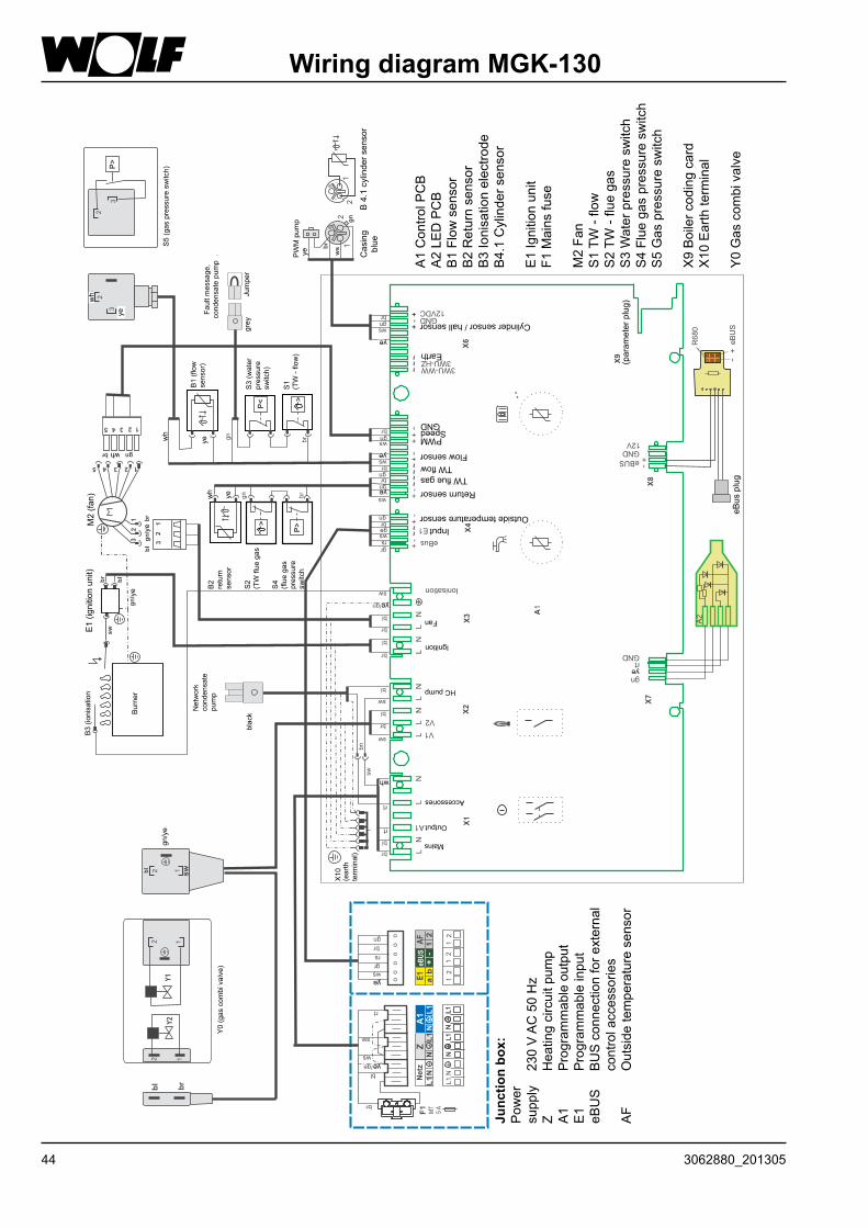
Wiring diagram MGK-130
Junc
tion
box:
Pow
er
supply230VAC50Hz
Z
Heatingcircuitpum
pA1
Program
mableoutput
E1
Program
mableinput
eBUS
BUSconnectionforexternal
controlaccessories
AF
Outsidetemperaturesensor
A1ControlPCB
A2LE
DPCB
B1Flow
sensor
B2Returnsensor
B3Ionisationelectrode
B4.1Cylindersensor
E1Ignitionunit
F1Mainsfuse
M2Fan
S1TW
-flow
S2TW
-fluegas
S3Waterpressuresw
itch
S4Fluegaspressuresw
itch
S5Gaspressuresw
itch
X9Boilercodingcard
X10Earthterminal
Y0Gascom
bivalve
Y0(gascom
bivalve)
gn/ye
B3(ionisation
Burner
E1(ignitionunit)
M2(fan)
wh
ye
wh
S5(gaspressuresw
itch)
Network
condensate
pum
p
black
B2
return
sensor
wh
wh
ye
ye
S2
(TWfluegas
S4
(fluegas
pressure
switch
B1(flow
sensor)
S3(water
pressure
switch)
S1
(TW-flow)
Faultm
essage,
condensatepum
p
grey
Jumper
X10
(earth
terminal)
Mains
Output
wh
Accessories
ye
ye
HCpump
Ignition
Fan
InputOutsidetemperaturesensor
ReturnsensorTWfluegas
TWflowFlowsensor
PWMSpeed
GND
Earth
Cylindersensor/hallsensor
PWMpum
p
Casing
blue
B4.1cylindersensor
ye
ye
ye
ye
ye
ye
(param
eterplug)
eBusplug
ye
ye
453062880_201305
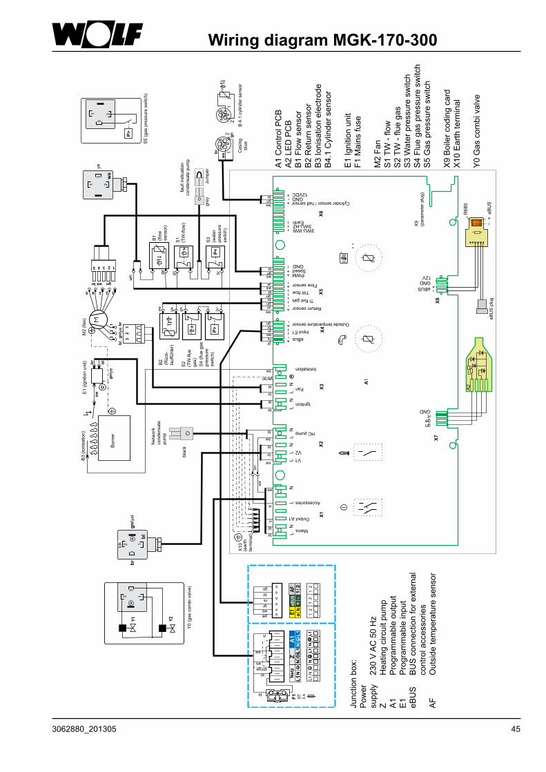
Wiring diagram MGK-170-300
5 4 3
3
2
2
1
1
M2
(Ven
tila
tor)
gn
/ge
br
br
bl
ws gn
21
12
E1
(Zü
nd
ein
heit
)B
3(I
on
isa
tio
n)
bl
br
gn
/ge
sw
Bren
ner
Netz
Ko
nd
en
sat-
pu
mp
e
Ge
hä
us
e
bla
u
Brü
ck
e
Stö
rm
eld
un
g
Ko
nd
en
sa
tpu
mp
e
21
12
Y0
(Ga
sk
om
biv
en
til)
Y2
Y1
X10
(Sch
utz
-
leit
er-
kle
mm
e)
345 2 1
32
1
LN
LN
LL
NL
NL
NL
N+
-~
+-
+-
~~
~~
~+-
++-
~~
~+
+-
Netz
AusgangA1
Zubehör
V1
V2
HK-Pumpe
Zündung
Ventilator
Ionisation
eBUS
eB
US
eB
US
-Ste
cke
r
gngertGND
GND
R6
80
12V
+
+
-
-
eBus
EingangE1
Außenfühler
Rücklauffühler
TW-Abgas
TW-Vorlauf
Vorlauffühler
PWMDrehzahl
GND
3WU-WW3WU-HZ
Masse
Speicherfühler/HallsensorGND
12VDC
B2
(Rü
ckla
uf-
füh
ler)
S2
(TW
-Ab
gas)
S4
(Ab
gas-
dru
ck-
wäch
ter)
>
X1
X2
X3
X6
X4
X7
X5
X9
(Pa
ra
me
ters
tec
ke
r)
X8
br
gn
gra
u
sc
hw
arz
ws
B4
.1S
pe
ich
erfü
hle
r
br
wsgn
brgnws
gewsbrgnbrgngews
ge/gn
sw
bl
br
bl
br
bl
bl
br
sw
br
bl
sw
ws
sw
bn
rs
br
ws
gr
gn
ge
ws
ge
gn br
A2
A1
br
bl
ws
sw
gn
/ge
ge
AF
E1
eB
US
+-
12
ab
Ne
tzZ
A1
N
N
NL
1L
1L
1
oo
oo
oo
MT
3,15
A
F1
12
12
12
br
bl
gn/ge
sw
ws
rt
L1
N
gn
ws
gr
rs
br
ge
L1
NL1
NL1
NL1
N
rt
rt
B1
(Vo
rla
uf-
füh
ler)
S1
(TW
-
Vo
rla
uf)
>
ws
ge
gn br
S3
(Wasser-
dru
ck-
sch
alt
er)
P<
P>
2
2
11
1
2
3
3
3
S5
(Ga
sd
ru
ck
wä
ch
ter)
P>
1 2
3
Junctionbox:
Pow
er
supply230VAC50Hz
Z
Heatingcircuitpum
pA1
Program
mableoutput
E1
Program
mableinput
eBUS
BUSconnectionforexternal
controlaccessories
AF
Outsidetemperaturesensor
A1ControlPCB
A2LE
DPCB
B1Flow
sensor
B2Returnsensor
B3Ionisationelectrode
B4.1Cylindersensor
E1Ignitionunit
F1Mainsfuse
M2Fan
S1TW
-flow
S2TW
-fluegas
S3Waterpressuresw
itch
S4Fluegaspressuresw
itch
S5Gaspressuresw
itch
X9Boilercodingcard
X10Earthterminal
Y0Gascom
bivalve
5 A
B3(ionisation)
E1(ignitionunit)
M2(fan)
Y0(gascom
bivalve)
blk
yel
Burner
ye
ye
wh
S5(gaspressuresw
itch)
Network
condensate
pum
p
black
S4(fluegas
pressure
switch)
faul
t ind
icat
ion
condensatepum
p
B2
(Rück-
lauffühler)
S2
(TW-flue
gas)
B1
(flow
sensor)
S1
(TW-flow
)
S3
(water
pressure
switch)
grey
Jumper
Casing
blue
B4.1cylindersensor
X10
(earth
terminal)
yeye
ye
ye
ye
ye
ye
Mains
Output
Accessories
HCpump
Ignition
Fan
Input E1
Outsidetemperaturesensor
Returnsensor
Tlfluegas
TWflowFlowsensor
Speed
Earth
Cylindersensor/hallsensor
X9
(param
eterplug)
eBUSplug
46 3062880_201305
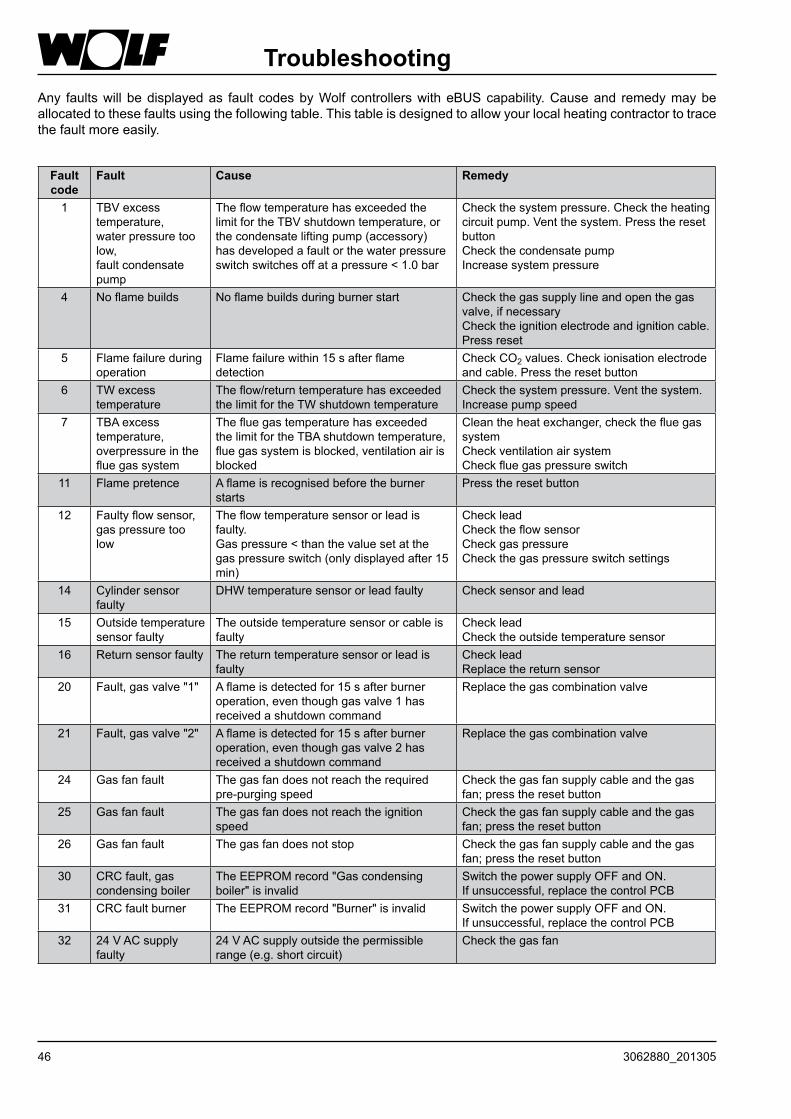
TroubleshootingAny faultswill bedisplayedas fault codesbyWolf controllerswitheBUScapability.Causeand remedymaybeallocatedtothesefaultsusingthefollowingtable.Thistableisdesignedtoallowyourlocalheatingcontractortotracethefaultmoreeasily.
Fault code
Fault Cause Remedy
1 TBVexcesstemperature,waterpressuretoolow,faultcondensatepump
TheflowtemperaturehasexceededthelimitfortheTBVshutdowntemperature,orthecondensateliftingpump(accessory)hasdevelopedafaultorthewaterpressureswitchswitchesoffatapressure<1.0bar
Checkthesystempressure.Checktheheatingcircuitpump.Ventthesystem.Presstheresetbutton Checkthecondensatepump Increasesystempressure
4 Noflamebuilds Noflamebuildsduringburnerstart Checkthegassupplylineandopenthegasvalve,ifnecessary Checktheignitionelectrodeandignitioncable. Pressreset
5 Flamefailureduringoperation
Flamefailurewithin15safterflamedetection
CheckCO2values.Checkionisationelectrodeandcable.Presstheresetbutton
6 TWexcesstemperature
Theflow/returntemperaturehasexceededthelimitfortheTWshutdowntemperature
Checkthesystempressure.Ventthesystem. Increasepumpspeed
7 TBAexcesstemperature,overpressureinthefluegassystem
ThefluegastemperaturehasexceededthelimitfortheTBAshutdowntemperature,fluegassystemisblocked,ventilationairisblocked
Cleantheheatexchanger,checkthefluegassystem CheckventilationairsystemCheckfluegaspressureswitch
11 Flamepretence Aflameisrecognisedbeforetheburnerstarts
Presstheresetbutton
12 Faultyflowsensor,gaspressuretoolow
Theflowtemperaturesensororleadisfaulty.Gaspressure<thanthevaluesetatthegaspressureswitch(onlydisplayedafter15min)
Checklead Checktheflowsensor Checkgaspressure Checkthegaspressureswitchsettings
14 Cylindersensorfaulty
DHWtemperaturesensororleadfaulty Checksensorandlead
15 Outsidetemperaturesensorfaulty
Theoutsidetemperaturesensororcableisfaulty
Checklead Checktheoutsidetemperaturesensor
16 Returnsensorfaulty Thereturntemperaturesensororleadisfaulty
Checklead Replacethereturnsensor
20 Fault,gasvalve"1" Aflameisdetectedfor15safterburneroperation,eventhoughgasvalve1hasreceivedashutdowncommand
Replacethegascombinationvalve
21 Fault,gasvalve"2" Aflameisdetectedfor15safterburneroperation,eventhoughgasvalve2hasreceivedashutdowncommand
Replacethegascombinationvalve
24 Gasfanfault Thegasfandoesnotreachtherequiredpre-purgingspeed
Checkthegasfansupplycableandthegasfan;presstheresetbutton
25 Gasfanfault Thegasfandoesnotreachtheignitionspeed
Checkthegasfansupplycableandthegasfan;presstheresetbutton
26 Gasfanfault Thegasfandoesnotstop Checkthegasfansupplycableandthegasfan;presstheresetbutton
30 CRCfault,gascondensingboiler
TheEEPROMrecord"Gascondensingboiler"isinvalid
SwitchthepowersupplyOFFandON. Ifunsuccessful,replacethecontrolPCB
31 CRCfaultburner TheEEPROMrecord"Burner"isinvalid SwitchthepowersupplyOFFandON. Ifunsuccessful,replacethecontrolPCB
32 24VACsupplyfaulty
24VACsupplyoutsidethepermissiblerange(e.g.shortcircuit)
Checkthegasfan

473062880_201305
Fault code
Fault Cause Remedy
33 CRCfault;defaultvalues
TheEEPROMrecord"Masterreset"isinvalid
ReplacethecontrolPCB
34 CRCerrorBCC Parameterplugerror Exchangeparameterplug35 BCCmissing Parameterplughasbeenremoved Pluginthecorrectparameterplug36 CRCerrorBCC Parameterplugerror Exchangeparameterplug37 WrongBCC Theparameterplugisnotcompatiblewith
thecontrolboardPluginthecorrectparameterplug
38 BCC no. invalid Parameterplugerror Exchangeparameterplug39 BCCsystemerror Parameterplugerror Parametersteckerwechseln41 Flowmonitoring Returntemperature>Flow+25K Venttheheatingsystem,checkthesystem
pressure.Checktheheatingcircuitpump43 Burnerstarts
>20perhourFlowratethroughtheheatexchangertoolowor,incaseofcascade,measuringpointoftheheadertemperatureunsuitable,orpowerconsumptionofthecalorifierchargingtoolow.
Checktheflowrate;Headersensormustmeasurethecommonfeedtemperatureofthecascade.
50 Activation of the parameterplug
Theparameterplugisstilltobeactivated Presstheresetbuttontwice
52 Activation of the parameterplug
Theparameterplugisstilltobeactivated Presstheresetbuttontwice
60 Ionisationcurrentfluctuates
Thesiphonisblocked,orthefluegassystemisblocked,severestorm
Cleansiphon,checkfluegassystem,checkventilationair,checkmonitoringelectrode
61 Ionisationcurrentfails
Poorgasquality,monitoringelectrodefaulty,severestorm
Checkmonitoringelectrodeandlead
LEDconstantlyred Ionisationcableshortedoutorionisationelectrodeearthed(casing)
Checkionisationcableandpositionofelectrodetoburner.Presstheresetbutton
Troubleshooting
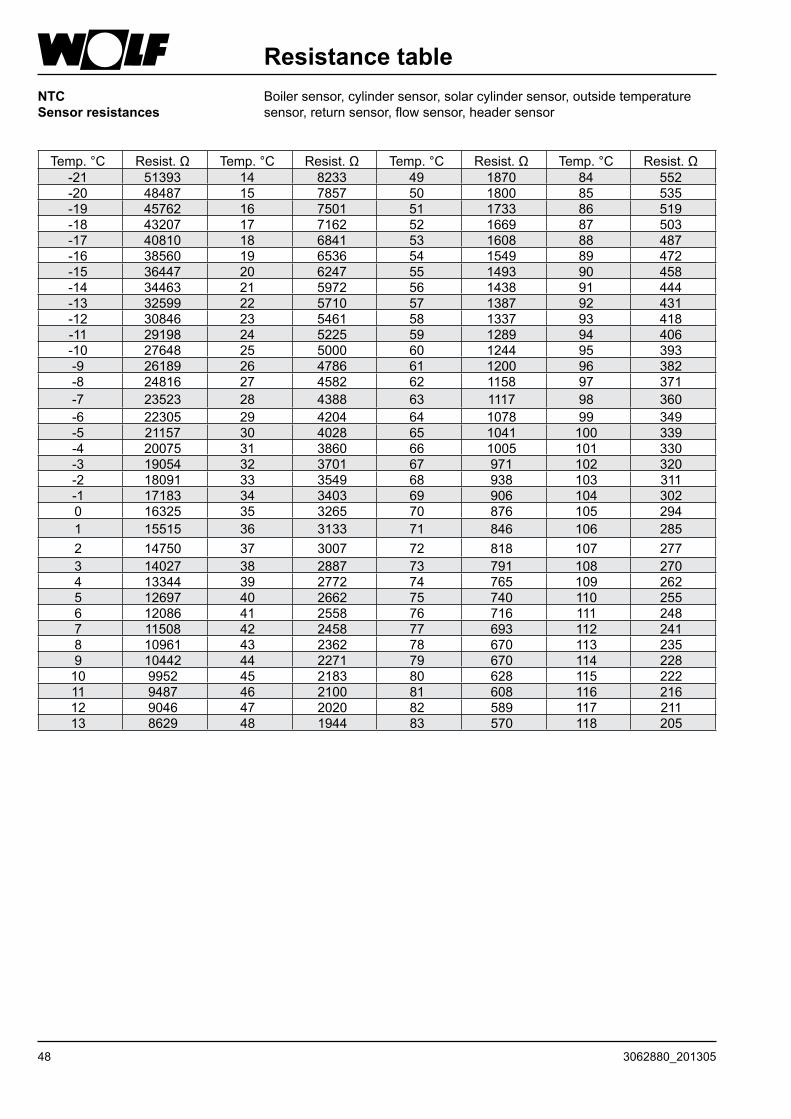
48 3062880_201305
Resistance tableNTCSensor resistances
Boilersensor,cylindersensor,solarcylindersensor,outsidetemperaturesensor,returnsensor,flowsensor,headersensor
Temp.°C Resist.Ω Temp.°C Resist.Ω Temp.°C Resist.Ω Temp.°C Resist.Ω-21 51393 14 8233 49 1870 84 552-20 48487 15 7857 50 1800 85 535-19 45762 16 7501 51 1733 86 519-18 43207 17 7162 52 1669 87 503-17 40810 18 6841 53 1608 88 487-16 38560 19 6536 54 1549 89 472-15 36447 20 6247 55 1493 90 458-14 34463 21 5972 56 1438 91 444-13 32599 22 5710 57 1387 92 431-12 30846 23 5461 58 1337 93 418-11 29198 24 5225 59 1289 94 406-10 27648 25 5000 60 1244 95 393-9 26189 26 4786 61 1200 96 382-8 24816 27 4582 62 1158 97 371-7 23523 28 4388 63 1117 98 360-6 22305 29 4204 64 1078 99 349-5 21157 30 4028 65 1041 100 339-4 20075 31 3860 66 1005 101 330-3 19054 32 3701 67 971 102 320-2 18091 33 3549 68 938 103 311-1 17183 34 3403 69 906 104 3020 16325 35 3265 70 876 105 2941 15515 36 3133 71 846 106 2852 14750 37 3007 72 818 107 2773 14027 38 2887 73 791 108 2704 13344 39 2772 74 765 109 2625 12697 40 2662 75 740 110 2556 12086 41 2558 76 716 111 2487 11508 42 2458 77 693 112 2418 10961 43 2362 78 670 113 2359 10442 44 2271 79 670 114 22810 9952 45 2183 80 628 115 22211 9487 46 2100 81 608 116 21612 9046 47 2020 82 589 117 21113 8629 48 1944 83 570 118 205

493062880_201305
Notice

50 3062880_201305
Notice

513062880_201305
Notice
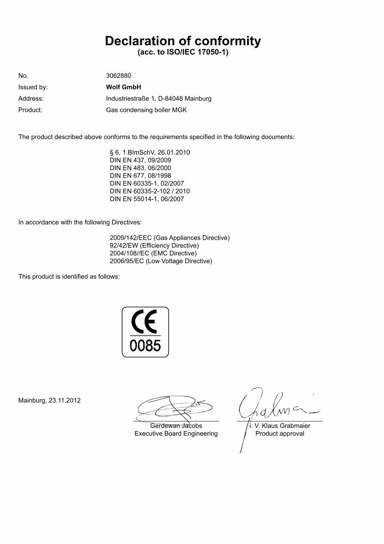
GerdewanJacobsExecutiveBoardEngineering
Mainburg,23.11.2012
Declaration of conformity(acc. to ISO/IEC 17050-1)
No. 3062880
Issuedby: Wolf GmbH
Address: Industriestraße1,D-84048Mainburg
Product: GascondensingboilerMGK
Theproductdescribedaboveconformstotherequirementsspecifiedinthefollowingdocuments:
§6,1.BImSchV,26.01.2010DINEN437,09/2009DINEN483,06/2000DINEN677,08/1998DINEN60335-1,02/2007DINEN60335-2-102/2010DINEN55014-1,06/2007
InaccordancewiththefollowingDirectives:
2009/142/EEC(GasAppliancesDirective)92/42/EW(EfficiencyDirective)2004/108//EC(EMCDirective)2006/95/EC(LowVoltageDirective)
Thisproductisidentifiedasfollows:
0085
i.V.KlausGrabmaierProductapproval