ASSAM POWER DISTRIBUTION COMPANY LTD - apdcl.org · The PRO, APDCL, Bijulee Bhawan, Paltan Bazar,...
91
1 | Page ASSAM POWER DISTRIBUTION COMPANY LTD. BID DOCUMENT FOR CONSTRUCTION OF DEDICATED 11 kV FEEDER WITH 11 kV AAAC, TRIPLE EXTRUDED, UV PROTECTED, LONGITUDINALLY WATER BLOCKED AND NON- COMPACTED MEDIUM VOLTAGE COVERED CONDUCTOR AGAINST THE SCHEME “CONSTRUCTION OF DEDICATED FEEDER FOR TEA GARDEN” UNDER PACKAGE – A: DIBRUGARH ELECTRICAL CIRCLE. PACKAGE – B: TINSUKIA ELECTRICAL CIRCLE. ON “TURNKEY” MODE UNDER SOPD 2018-19 NIT NO. APDCL/CGM (HQ)/ MAT/SOPD 2018-19/NIT NO-19/2 OFFICE OF THE CHIEF GENERAL MANAGER (HQ), APDCL
Transcript of ASSAM POWER DISTRIBUTION COMPANY LTD - apdcl.org · The PRO, APDCL, Bijulee Bhawan, Paltan Bazar,...

1 | P a g e
ASSAM POWER DISTRIBUTION COMPANY LTD.
BID DOCUMENT FOR
CONSTRUCTION OF DEDICATED 11 kV FEEDER WITH 11 kV AAAC, TRIPLE
EXTRUDED, UV PROTECTED, LONGITUDINALLY WATER BLOCKED AND NON-
COMPACTED MEDIUM VOLTAGE COVERED CONDUCTOR AGAINST THE
SCHEME “CONSTRUCTION OF DEDICATED FEEDER FOR TEA GARDEN”
UNDER
PACKAGE – A: DIBRUGARH ELECTRICAL CIRCLE.
PACKAGE – B: TINSUKIA ELECTRICAL CIRCLE.
ON
“TURNKEY” MODE
UNDER
SOPD 2018-19
NIT NO. APDCL/CGM (HQ)/ MAT/SOPD 2018-19/NIT NO-19/2
OFFICE OF THE CHIEF GENERAL MANAGER (HQ), APDCL

2 | P a g e
INDEX
Notice Inviting Tender 4-7
Tender Inviting Proposal 9-22
BOQ of Packages &Tender Proforma-Part-II (Price Bid) 24-25
PRICE BID FORMAT 26-29
GENERAL REQUIREMENT 31-33
Forms of Bid 35-46
Technical Specifications 48-82
Guaranteed Technical Particulars 84-91

3 | P a g e
SECTION -1 NOTICE INVITING TENDER

4 | P a g e
ASSAM POWER DISTRIBUTION COMPANY LTD.
CIN: U40109AS2003SGC007242 Website:www.apdcl.org
Chief General Manager (HQ), APDCL
------------------------------------------------------------------------------------------------------------------------
Memo No.APDCL/CGM (HQ)/ MAT/SOPD 2018-19/NIT NO-19/2/ Dated: Copy to:
1. The P.S to the Chairman, APDCL, for kind apprisal of the Chairman, APDCL. 2. The P.S. to the MD, APDCL for kind apprisal of the MD, APDCL. 3. The Chief General Manager (F&A), APDCL, Bijulee Bhawan, Paltanbazar. Guwahati-1, for kind information. 4. The O.S.D. to the Chairman, APDCL, Bijulee Bhawan, Paltan Bazar, Guwahati for information and publication in
official website. 5. The PRO, APDCL, Bijulee Bhawan, Paltan Bazar, Guwahati for publication of the above tender in one issue of
National English Newspaper, “The Assam Tribune” and one Assamese daily newspaper. 6. Relevant Office file.
Sd/-
Chief General Manager (HQ), APDCL
Office of the Chief General Manager(HQ), APDCL, Bijulee Bhawan, Paltanbazar Guwahati-781-001,E:Mail:[email protected], Tele Fax: 0361-2735395
TENDER NOTICE No. 19/2 E-tenders in two parts viz. (1) Techno- Commercial Bids and (2) Price Bids, with validity up to 180 days are
hereby invited from experienced Electrical Contractors/reputed OEMs (Individual or Joint Venture) having
valid electrical contractor license up to 33KV, issued by the competent authority and having sufficient
experience in erection, stringing & commissioning of 11kV overhead line with AAAC triple extruded, UV
protected, longitudinally water blocked and non-compacted Medium Voltage Covered Conductor (MVCC)
as per relevant codes under the scheme “Construction of Dedicated Feeder for Tea Garden” against
SOPD 2018-19 on full Turnkey mode of contract. Interested Electrical Contractors/reputed OEMs may view
the detailed Tender Notice and specification by visiting APDCL website www.apdcl.org or
www.assamtenders.gov.in from 12.03.2019.

5 | P a g e
ASSAM POWER DISTRIBUTION COMPANY LTD. CIN: U40109AS2003SGC007242
Website:www.apdcl.org
NIT NO. APDCL/CGM (HQ)/ MAT/SOPD 2018-19/NIT NO-19/2/ Dtd:
E-tenders in two parts viz. (1) Techno- Commercial Bids and (2) Price Bids, with validity up to 180 days are hereby
invited from experienced Electrical Contractors/ reputed OEMs (Individual or Joint Venture) having valid electrical contractor
license up to 33KV, issued by the competent authority of Govt. of Assam, having sufficient experience in erection, stringing
& commissioning of 11 kV overhead line with 70sqmm AAAC, triple extruded, UV protected, longitudinally water blocked
and non compacted Medium Voltage Covered Conductor (MVCC) as per relevant codes under the scheme “Construction
of Dedicated Feeder for Tea Garden” against SOPD 2018-19 on full Turnkey mode of contract.
Package
Work description
Average annual
turnover (Rs. in Crores)
EMD amount (Rs. in lakh)
Period of completion
in days
Package A
Construction of 11kV dedicated feeder (25.5 Km) with
70sqmm AAAC, triple extruded, UV protected, longitudinally
water blocked and non compacted Medium Voltage Covered
Conductor (MVCC) as per relevant standard under the
scheme “Construction of Dedicated Feeder for Tea
Garden” against SOPD 2018-19 on full Turnkey mode of
contract under Dibrugarh Electrical Circle.
20.00 15.00
270 (Two
Hundred
Seventy)
days from
the date of
issue of work
order)
Package B
Construction of 11kV dedicated feeder (18.0 Km) with
70sqmm AAAC, triple extruded, UV protected, longitudinally
water blocked and non compacted Medium Voltage Covered
Conductor (MVCC) as per relevant standard under the
scheme “Construction of Dedicated Feeder for Tea
Garden” against SOPD 2018-19 on full Turnkey mode of
contract under Tinsukia Electrical Circle.
15.00 15.00
270 (Two
Hundred
Seventy)
days from
the date of
issue of work
order)
COST OF TENDER PAPER: The Bid documents can be downloaded from the websites: www.assamtenders.gov.in or
www.apdcl.org free of cost for tender submission purpose. The bidder using downloaded documents will mandatorily attach
an A/C payee Demand Draft/ Banker’s Cheque (non-refundable) of Rs.10,000.00 (Rupees ten thousand) only+GST @18%
i.e Rs 11,800.00 ( Rupees ElevenThousand Eight Hundred) only with their Bid for each package separately, duly pledged in
favour of “ASSAM POWER DISTRIBUTION CO. LTD. as cost of tender paper. Any bid without payment of cost of tender
for the above package will be rejected outright.
1. Source of fund: Scheme -“Construction of Dedicated Feeder for Tea Garden” against SOPD 2018-19.
2. Earnest money: As shown in the table above. The EMD in the form of B.G covering the validity period of 6 months is to be pledged in favour of the APDCL, payable at Guwahati. The APDCL’s General Condition of Supply and Erection, 2009 and Additional Terms and Conditions are enclosed here with for guideline.
3. Area of Work:
Package – A: Under Dibrugarh Electrical Circle (25.5Km) a. From 33/11kV Maderkhat Sub-Station to Mohanbari Tea Estate – 10.0 km. b. From 33/11kV Bhadoi Pachali Sub-station to Sitapur, Moahabirbari, Hatijan, Anadabari and Monpasand Tea Estate –11 Km. c. From 33/11kV Tengakhat Sub-Station Bagrodia Chai, Bagrodia Plantation, R.D Tea & Lengrai Tea Estate - 4.5 Km

6 | P a g e
Package – B: Under Tinsukia Electrical Circle (18Km)
a. From 33/11kV Naupukhuri Sub-Station to Itakhuli and Kehung Tea Estate – 5.0 km b. From 33/11kV Naupukhuri Sub-Station to Sewpur, Deodarshan, Monkhuli, Chototingrai, Fussion, Bahadur and Mahakali Tea
Estate – 13.0 km
4. Eligibility Criteria:
a) The bidder must have valid electrical contractors and supervisor’s license upto 33kV issued by the competent authority of Govt. of Assam, subject to the electrical supervisors certificate of competency and workman permit.
b) Average Annual turnover of the bidder for the last three financial years (FY 2015-16, FY 2016-17 & FY 2017-18) for the work should be as mentioned and duly certified by registered Chartered Accountant with Registration No.
c) Past and present performance of the bidder in ASEB/APDCL or any of its successor companies will be taken into account to decide the eligibility as per clause mentioned in the detailed bid document.
d) The bidder must have the experience of similar work of MVCC line along with supply of various hardware &
accessories required for installation of MVCC conductor and must have successfully erected and commissioned at least 350KM of 11kV or above voltage class MVCC line within India as on the date of bid opening and must be in satisfactory operation for at least 3 (three) years.
e) The bidder must not be involved in any litigation with ASEB/APDCL or any other successor company of ASEB. The bidder should submit a declaration to that effect.
f) The bidder must be financially solvent so as to execute the proposed work. Financial solvency certificate from the concerned bank must be submitted.
g) Financial resources: The bidder shall have to specify proposed source of financing, such as liquid assets, unencumbered real assets, line of credit and other financial means, net current commitments, available to meet the total construction cash flow demand of the subject contract (evaluation & qualification criteria).
h) Other Eligibility Criteria may be seen at detail bid document.
5. Bid validity: 180 days from the date of submission of Bid.
6. Date of submission of Tenders:
a. Tender upload date: 12.03.2019 at 17.30 Hrs. b. Pre Bid meeting : 19.03.2019 at 14:00Hrs. c. Bidding Submission Date: From 11:00Hrs. of 20.03.2019 to 15:00Hrs of 01.04.2019 on the bidding portal. d. Bid Opening Date for techno commercial evaluation: 02.04.2019 at 12:00 Hrs. in the O/o the undersigned.
Hard copy format except price quote shall be submitted from 11:00Hrs. of 20.03.2019 to 01.04.2019 till 15.00 Hrs.
7. Date of opening of Bid:
Techno commercial bids will be opened on 02.04.2019 at 12:00 Hrs
8. Date of opening of Price Bids will be intimated subsequently to the Techno-Commercially qualified Bidders.
The bidders shall have to deposit one set of duly stamped & signed hard copy of the Bid Data Sheet and other documents as specified in the bid. The Price bid is to be submitted online only. The Price bid in hard/ paper form shall not be accepted / entertained.
9. Part-I of the Bid shall consist of information of all Technical Bidding Schedules (GTP) of all items as per Bill of Quantity (BOQ), Copy of the Licences, GST registration certificate, duly certified proof of turnover, company profile, experience certificate etc.
Part-II shall consist of Price Bidding Schedules with all quantities and prices filled up as per annexure provided in the detail bid document.
10. Only those bidders who are found acceptable in Part-I Bid i.e. Techno Commercial bid shall be considered in Price Bid. The date and time of opening of Part-II Bid (Price) shall be communicated to those bidders whose bids are qualified for opening.
11. Corrigendum, if any, would be published online on the website and will be deemed to be a part of the bid document and binding on all the bidders.
12. The bidding documents are not transferable and cost of bidding document is not refundable under any circumstances.

7 | P a g e
13. The undersigned reserves the right to reject any /all bids without assigning any reason thereof, and to accept any tender or part thereof advantageous to APDCL and to award the contract to one party or split up the contract amongst different bidders. Decision of undersigned is final and binding on all.
Sd/-
Chief General Manager (HQ) APDCL, 4th floor, Bijulee Bhawan
Paltanbazar, Guwahati-781001 Memo No: APDCL/CGM (HQ)/ MAT/SOPD 2018-19/NIT NO-19/2/ Date: Copy to:-
1. The P.S to the Chairman, APDCL, for kind apprisal of the Chairman, APDCL. 2. The P.S. to the MD, APDCL for kind apprisal of the MD, APDCL. 3. The Chief General Manager (F&A), APDCL, Bijulee Bhawan, Paltanbazar. Guwahati-1, for kind information. 4. The O.S.D. to the Chairman, APDCL, Bijulee Bhawan, Paltan Bazar, Guwahati for information and publication in
official website. 5. Relevant Office file.
Sd/-
Chief General Manager (HQ), APDCL
Office of the Chief General Manager(HQ), APDCL, BijuleeBhawan, Paltanbazar Guwahati-781-001,E:Mail:[email protected], Tele Fax: 0361-2735395

8 | P a g e
SECTION 2
TENDER INVITING PROPOSAL

9 | P a g e
ASSAM POWER DISTRIBUTION COMPANY LIMITED OFFICE OF THE CHIEF GENERAL MANAGER(HQ)
TENDER INVITING PROPOSALS WITH TERMS & CONDITIONS
1. Name of work:
Construction of 11kV dedicated line (25.5 Km & 18.0 Km) with 70sqmm AAAC triple extruded, UV protected,
longitudinally water blocked and non compacted Medium Voltage Covered Conductor (MVCC) as per relevant standard
under the scheme “Construction of Dedicated Feeder for Tea Garden” against SOPD 2018-19 on full Turnkey mode
of contract in 2 (two) Packages as described below
.
Package – A (25.5 Km) under Dibrugarh Electrical Circle. a. From 33/11kV Maderkhat Sub-Station to Mohanbari Tea Estate – 10.0 km. b. From 33/11kV Bhadoi Pachali Sub-station to Sitapur, Moahabirbari, Hatijan, Anadabari and Monpasand Tea Estate –11.0
Km. c. From 33/11kV Tengakhat Sub-Station Bagrodia Chai, Bagrodia Plantation, R.D Tea & Lengrai Tea Estate - 4.5 Km
Package – B (18.0 Km) under Tinsukia Electrical Circle.
a. From 33/11kV Naupukhuri Sub-Station to Itakhuli and Kehung Tea Estate – 5.0 km b. From 33/11kV Naupukhuri Sub-Station to Sewpur, Deodarshan, Monkhuli, Chototingrai, Fussion, Bahadur and Mahakali Tea
Estate – 13.0 km
2. Intent of the Tender Enquiry:
The intent of the Tender Enquiry is to invite proposals from the prospective and relevantly experienced and financially
sound electrical contractor(s)/reputed OEMs (individual or joint venture) to carry out the works as mentioned above on
full turnkey mode.
3. Scope of Work
The various activities under the scope of work shall among other related aspects cover the following-
i. Procurement, supply and erection of all materials to the site required for the work.
ii. Arrange inspection / testing of any/all items ordered at manufacturer’s works for officer deputed by APDCL for
such inspection/testing. All cost related to the inspection will be borne by the contractor.
iii. Site unloading, storage and handling of all materials supplied including watch and ward for safe custody.
iv. Site fabrication work as per requirement.
v. Submission of implementation schedule from the date of award of contract for: -
Route survey for laying new line.
Erection, testing and commissioning of all materials/equipment supplied/system installed.
vi. Project management and site organization.
vii. Obtaining clearance from statutory Agencies, Government Departments, Village Panchayats etc. wherever
necessary.
viii. Submission of guarantee technical specification/Test Certificate/Drawings etc. of all materials supplied.
ix. A list of various items normally involved in proposed type of work is provided in this document. This, however, is not to be considered as limiting but only typical. Vendors’ scope will include all other items and materials as may be required to effectively complete the work.
x. GIS mapping. xi. Return of dismantle materials if any, shall be returned to the concerned Sub-Division. xii. Required Jungle cutting.
Above all, the scope of work of the vendor/contractor will include all items and facilities as may be necessary to complete
the electrification work on turnkey basis and as binding requirement.
4. Basic specification of the various equipment/ works to be supplied /carried out
i. All equipment supplied shall conform to the requirement of relevant ISS (BIS) or other applicable relevant standards as approved by ASEB/Company and that of REC specification and construction standards.

10 | P a g e
ii. All materials supplied shall be erected, protected as per approved standard practice for proposed type of electrical work so as to supply electricity to the consumers most effectively and in an intrinsically safe manner.
iii. All equipment supplied and installed shall provide easy and effective:
Maintainability
Reliability
Availability
Long life
All equipment supplied and installed shall be provided stable and adequate weather protection, system
earthing etc. LA should be earthed separately.
iv. All items, which may require frequent opening up/ dismantling for maintenance, shall be adequately sealed against any tampering/ theft etc.
v. Generally supply and erection of materials and system shall meet the requirement of construction standard being followed in the electrification work.
5. Basic qualifying requirement:
To be qualified for the package the bidder must compulsorily meet the following minimum criteria.
A. Technical
The prospective bidder must fulfill the following qualifying requirements:
a) The bidder must have valid electrical Contractor’s and Supervisor’s License (HT minimum up to 33 KV) issued by competent Licensing Authority of Govt. of Assam. In case, the bidder does not have the licenses from the Licensing Authority of Govt. of Assam but has valid licenses from other Licensing Authority under the Electricity Act 2003, the bidder will have to obtain the same from the Licensing Authority of Govt. of Assam in case of award of contract.
b) The bidder must have the experience of similar work of MVCC line along with supply of various
hardware & accessories required for installation of MVCC conductor and must have successfully erected and commissioned at least 350KM of 11kV or above voltage class MVCC line within India as on the date of bid opening and must be in satisfactory operation for at least 3 (three) years.
c) The experience certificate must be from an officer not below the rank of Executive Engineer of electrical utilities.
d) The bidders shall ensure that the materials to be supplied are from OEMs having valid ISO certification. Documentary evidence to this effect must be submitted with this bid.
e) In case of Micro/Small/Medium Enterprise units, provisions of Procurement Policy, Assam 2015 shall apply.
B. Financial a. Average annual turnover of the bidder for the last three consecutive financial years should be as per NIT and the
annual turnover must be certified by a registered Chartered Accountant. This should be supported by the copy of the income tax return submitted by the firm for the last three previous years. In case of joint venture firms, the figures of average annual turnovers for each Joint Venture partners shall be added together to determine the bidder’s compliance with the minimum average turnover requirement for the package. However, the lead partner must meet at least 40% and each of the other partners must meet at least 25% of the minimum average annual turnovers criteria required for each package as per NIT.
b. If the total work in hand against the works of APDCL or its successor companies and other agencies exceed more than 3(three) times the average annual turnover of the bidder, the bid shall be treated as non-responsive.
c. The bidder shall furnish GST registration certificate, Employee Provident fund and valid Labour License (wherever applicable).
d. The bidder shall furnish copy of their Pan Card. The card must be in the name of the firm if the bidder is a firm. If it is a joint venture copy of Pan Card of both the partner/firms must be submitted.
e. Joint venture agreement should be a registered one or certified by Notary. f. Power of attorney should be a registered/ notarized one. g. Formal authority, Registered/Notarized for signing the tender or other documents on behalf of the firm / individual
must be submitted along with the bid. In case of registered company Board’s resolution of the company for authorized signatory should be furnished.
h. Notwithstanding anything stated herein above, APDCL reserves the right to assess the capacity and capability of the bidder to execute the work, should the circumstance warrant such assessment in the overall interest of APDCL.

11 | P a g e
6. Agreement:
The successful bidders shall have to enter in to an agreement with APDCL within 7(seven) days from the date of
issue of detailed work order (LOA).
7. Performance Guarantee:
The successful bidder shall have to deposit performance security deposit in the shape of Bank Guarantee from a
scheduled commercial bank of RBI pledged in favour of Assam Power Distribution Company Limited as per
prescribed proforma for an amount equivalent to 10% (ten percent) of the awarded value. The BG shall be furnished
to the Chief General Manager(HQ), APDCL along with acceptance of Letter of Intent (LOI). The validity of the BG
shall be for a period of 30 (thirty) months beyond the scheduled date of completion of work as per work order with
additional one month claim period. If the supplier fails or neglect to perform any of his obligations under the contract,
the APDCL shall have the right to forfeit in full or in part thereof at its absolute discretion the performance security
deposit furnished by the supplier. No interest shall be payable on such deposits.
8. Joint Venture Requirement i. In case of successful Bidder, one form of agreement (at annexure) shall have to be signed by both the
partners so as to be legally binding on both. ii. One of the partners shall be authorized as the lead partner and authorization shall be evidenced by
submitting a Power of Attorney signed by legally authorized signatories of the both the partners. Both the JV partners must have valid Electrical Contractor’s License of required level issued by the Licensing Authority.
iii. The lead partner shall be authorized to incur liabilities, receive payments, and receive instructions for and on behalf of any or all partners of the joint venture for entire execution of the contract.
iv. All the partners of the joint venture shall be jointly and severally liable for the execution of the contract in accordance with the contract terms and conditions. A relevant statement to this effect shall be included in the authorization mentioned above as well as in the bid form and the form of agreement (in case of successful bidder).
v. A copy of the joint venture agreement shall be submitted with the bid. vi. The figure of average annual turnovers for the joint venture partners shall be added together to determine
the bidder’s compliance with the minimum average turnover requirement for the package. However, the lead
partner must meet at least 40% and other partner must meet the at least 15% of the minimum average
annual turnover criteria given in the Tender.
vii. Apart from above, the following are the documents that need to be submitted by each individual partners
constituting the Joint Venture-
a. Company/Firm registration no.
b. List of order executed and order in hand
c. Bank solvency certificate
d. Labour license
e. GST registration
f. Provident fund Registration certificate
viii. The Submission of E-tender should be digitally signed by the lead partner of the JV only.
9. Other requirements:
The Bidder -
i) Should be acquainted himself with relevant conditions of the local geography and socio economic setup of the different location of the State and being capable accordingly to mobilize, organize and expedite the activities.
ii) Should have adequate working personnel comprising of Electrical/ Mechanical engineers, electrical supervisor, skilled and unskilled labour to be deputed to the proposed assignment.
iii) Should be conversant with the code/ standards applicable to proposed type of work. ISS, REC,EN or other relevant guidelines.
10. Understanding of bid documents:
A prospective Bidder is expected to examine all instructions, forms, terms, technical specifications, tender drawings
and scope of works in the Bid documents and fully inform himself as to all the conditions and matters which may in

12 | P a g e
any way affect the scope of work or the cost thereof. Failure to furnish all information required in the Bid document or
submission of a Bid not substantially responsive to the Bid document in every respect will be at the Bidder’s risk and
may result in the rejection of its bid.
11. Submission of bid The bidder shall submit the techno-commercial bid cum price bids electronically by using the web portal
www.assamtenders.gov.in only.
a. Techno-commercial bid
Techno-commercial bid should be submitted in a sealed envelope, Superscripting “Techno-commercial bid with
EMD” with name of bidder, full address, NIT reference & package no. Under this, will be included and defined
bidders scope of work, responsibilities, guarantees, specification of equipment, commercial terms and conditions,
bidder’s company credentials, experience of similar assignments, registration details, etc. as per requirement.
Tender proforma for techno-commercial Bid is enclosed as Annexure-I.
b. Earnest Money Deposit (EMD):
The Tender must be accompanied with earnest money as mentioned in the NIT and it is to be deposited in the form
of Bank Call Deposit/NSC/Term Deposit/ BG from any scheduled commercial bank of RBI pledged in favour of
“ASSAM POWER DISTRIBUTION COMPANY LIMITED”. The EMD should be valid for a minimum period of 6
(six) months from the date of submission of tender along with Techno- Commercial bid. The earnest money of the
unsuccessful bidders will be released on finalization of the tenders. The EMD to the successful bidders will be
released on submission of 10% Performance Security Deposit to the undersigned as per clause of the bid
document. The EMD of the successful bidder will be forfeited on non-acceptance of Letter of Intent (LOI) within
the stipulated period mentioned in LOI
c. Submission of documents with technical bids
i) Detail list of makes and materials offered with catalogues, technical specification ,type tests certificate ,
performance certificate from utilities, authorization letter from manufacturer, customer list etc. ii) Certificates and testimonials in support of credentials of the bidder’s organization. iii) Details past experience along with present works in hand with awarded amount and progress report. iv) Brief write-up on methodology to carry out the assignment, if awarded. v) Details of manpower to be engaged for the assignments. vi) Any other information, the bidder may feel facilitative in evaluating the bid. vii) Copies of bidder and supervisor’s license, etc. viii) Certificate from Registered Charted Accountant in support of Annual turn over ix) Solvency certificate from Bank x) Certificate in support of performance of the bidder. xi) If the bidder is involved in any litigation with APDCL/ or any successor company of ASEB. The bidder should
furnish the information to that effect. xii) The bidder should submit the list of materials that are to be brought from outside the state. xiii) Guaranteed Technical Particulars (GTP) of major items as described in BOQ such as poles, conductors
(MVCC) , insulators, stay set, earth pipe etc as per bid requirements should invariably be submitted along Price bid should be with the tender otherwise tender is liable to be rejected. All the GTPs must also be submitted along with the requisite Type Test reports and test certificates as per applicable standards.
Note:-
a. If there is discrepancy between the unit price and the total price that is obtained by multiplying the unit price and quantity, the unit price shall prevail and total price should be corrected. If there is a discrepancy between the words and figures, the amount in word should prevail. If the bidder does not accept the correction of the errors as above, his bid will be rejected and the amount of bid guarantee/security will be forfeited.
b. If the price of any item is kept blank the highest rate quoted among the techno-commercial qualified bidder will be loaded for evaluation purpose. However if the bidder happens to be L-1 then rate against the item which the bidder has kept blank will be awarded as zero i.e. he will have to execute the work without any financial involvement.
c. No separate declaration offering discount on price will be allowed. Offered price in the price schedule will be final.

13 | P a g e
d. Pre-bid meeting: Prospective bidders are requested to be present in the Pre-bid meeting on the date mentioned in the NIT without fail, so that all kind of queries/ clarifications can be discussed. APDCL will not accept any complain, request for correction/modification etc. after holding of pre-bid meeting.
e. (A) Estimation of material requirement: The total quantity of materials required is indicated in the BOQ. The cost estimate is prepared on the basis of latest Schedule of Rate of APDCL and the same can be collected from the office of CGM (HQ) if required by the bidder.
(B) Quantity Variation: There may be increase or decrease in quantity of individual item subject to the condition that the corresponding change in total contract value does not increase or decrease by more than 10% keeping the unit rate of individual material and labour unchanged. The variation which may occur must have the approval of CGM (HQ).
12. Ceiling on acceptance of bid value
As a deterrent for cartel formation APDCL at its discretion have the right to scrap the tender if values quoted by all
the bidders is equal to or above 25% of the working estimate. Also the price bids whose total quoted value is
equal to or below 15% of the working estimate, the bid is liable to be rejected by APDCL.
13. Award of work: i) The evaluation of bids will be carried out in two part, technical bid and price bid. The price bid will be
opened and evaluated only of those bidders who qualified in technical bid only. ii) APDCL is not bound to accept the lowest quoted rate if the bidder is not responsive as per requirement
of APDCL’s terms and conditions. iii) Work should be started within fifteen (15) days from the date of issue of the work order, failing which
order will be cancelled without further correspondence. iv) The successful bidder must have to complete survey works within 1 (one) month from the date of issue
of work order & submit quantity variation within that period.
v) All materials installed shall be under custody of the contractor till the date of commissioning and charging. The properties will be taken over by APDCL, only after satisfactory commissioning and charging.
vi) Work may be allotted to more one responsive bidders at L1.
14. All quoted rate should be inclusive of GST and all taxes as applicable as per prevailing rate.
15. Period of completion: 270 (Two hundred seventy) days from the date of issue of work order.
NB: The project being a time bound GOA funded priority scheme the intending bidder who feel
competent enough to complete within the stipulated period should only participate. No extension of
work will be granted.
16. Implementation schedule:
Comprehensive implementation schedule of work for the mentioned works
Sl No Description
EXECUTION PERIOD
10 d
ays
20 d
ays
45 d
ays
45 d
ays
120
days
30 d
ays
1 Signing of Agreement
2 Survey works & submission of drawings/GTP
3 Manufacture & supply of materials as per BOQ
4 Erection of MVCC Line
5 Testing & commissioning

14 | P a g e
17. Termination of work order:
Company reserves the right to terminate the work order at any stage in accordance with the Company’s
General Condition of Supply and Erection in force.
18. Terms of Payment:
a. During the currency of the contract, maximum 2(Two) nos. of progressive bill will be entertained. The progressive bill will be for the actual work done including supply & erection of the materials for which 60% of the billed amount will be paid retaining the balance 40% by APDCL. Final bill will be paid after satisfactory completion & commissioning of the project subject to validity of performance guarantee submitted as per PBG clause. No mobilization advance will be entertained.
b. All payment shall be made from the office of the CGM (HQ), APDCL. The bills after due verification by the concerned SDE, passed by the concerned Assistant General Manager and countersigned by the concerned CEO will be placed to the CGM (HQ) for payment. Progress report against the work must be enclosed with each bill (format for progress report to be submitted will be supplied along with the work order).
c. The right of the contractor/supplier to have payment or reimbursement of any cost for execution of works/supply of materials as the case may be, against this order will be forfeited or deemed to have been relinquished if the claim for it is not preferred to the appropriate authority within 6(Six) months from the date of completion or deemed completion as per clause of Company’s GCSE.
19. Project Management and site Organizations:
In Consideration of the tight schedule of the project, the successful bidder(s) /Contractor(s) shall exercise
systematic closely controlled project management system with the aid of commonly used soft tools. Following
are the major activities/deliverables to be organized /generated for submission to the Board.
(I) Liaison/Construction offices will be established in each Circle of APDCL. (II) Work Progress Report:
Progress monitoring by the contractor as per implementation schedule and approved milestones. Fortnightly progress report shall be submitted to the concern Deputy General Manager(HQ), Senior
Manager & Sub-Divisional Engineers. The progress report will highlight the points like, work completion vis-à-vis planned, plan for next
working period, delay analysis vis-à-vis committed schedule with reasons and remedies, etc.
(III) Site Organization- The bidder at each working site shall establish the following.
Store house Site fabrication facilities Construction supervision office.
All offices shall be adequately furnished and staffed so as to take all site decisions independently without
frequent references to head Work’s/offices.
20. Guarantees and Penalties:
a) Liquidated Damages (LD) The proposed work is on top priority of Government of Assam and therefore has to be completed within stipulated/agreed schedule. Any delay beyond that will attract penalty as per Company’s General condition of supply and erection.
b) Equipment and system installed (other than APDCL’s supply) shall be guaranteed individually for integrated operations for a period of 24 (twenty) months from date of commissioning of a system in general. In case of detection of any defect in individual equipment or system as a whole, the same shall be replaced by the bidder free of cost within 15 days of intimation by the Company’s representative.
c) Warranty from the manufacturer shall be produced along with manufacturer’s test certificate for all equipment/ materials covered under Manufacturer’s warranty.

15 | P a g e
21. Approvals/Clearances: a) APDCL’s concerned CEO shall approve all site and documents prepared by the contractor for
construction of the Line. b) GTP and drawings of all equipment/ materials shall be approved by CGM (HQ), APDCL. c) The contractor shall obtain all statutory approvals and clearances from the statutory authorities before
charging the system at his/her own cost.
22. Testing & Inspection:
All the equipments / materials to be supplied and erected shall be tested /inspected at manufacturer’s works by
authorized officer/ Engineers of APDCL before dispatching them to worksite. The contractor shall intimate the
CGM (HQ) sufficiently in advance (at least 15 days) regarding the date of inspection of materials/ equipments at
manufacturer’s works. The materials shall be dispatched to site only after receipt of dispatch clearance issued
by the CGM (HQ) after satisfactory testing of the same. The cost of inspection by Company’s officials has
to be borne by the contractor.
23. Environmental Considerations:
While carrying out the assignment, no damage to environment /forests will be caused by the awardee. If so
done, the awardee will have to compensate the same to the satisfaction of the licensed Authority.
24. Submission of documents: a) With bids. i) Detail list of makes and materials offered with catalogues, technical specification, type test, performance
certificate, customer list etc. ii) Certificates and testimonials in support of credentials of the bidder’s organization. iii) Details past experience along with present works in hand with awarded amount and progress report. iv) Brief writ-up on methodology to carry out the assignment, if awarded. v) Details of manpower to be engaged for the assignments. vi) Any other information, the bidder may feel facilitative in evaluating the bid. vii) Copies of contractor and supervisor’s license, etc. viii) Certificate from Registered Charted Accountant in support of Annual turn over ix) Solvency certificate from Bank. x) Earnest money deposit and tender fee along with Techno- Commercial bid. xi) Certificate in support of performance of the bidder.
b) During project execution
i) All documents for approval shall be submitted in 3 (three) copies. ii) All final documents to be submitted to statutory organizations will be furnished as per requirement of the
authority.
25. Funding of the project: The proposed work is funded by the G.O.A. under “SOPD 2018-19”
26. Termination of contract on Contractor’s default
If the Contractor neglect to execute the Works with due diligence and expertise or shall refuse or neglect to comply with any reasonable order given to him, in the Contract by the Engineer in connection with the works or shall contravene the provisions of the Contract, the owner may give notice in writing to the contractor to make good the failure, neglect or contravention complained of. Should the contractor fail to comply with the notice within thirty (30) days from the date of serving the notice, then and in such case the Owner shall be at liberty to employ other workmen and forthwith execute such part of the works as the Contractor, may have neglected to do or if the owner shall think fit, without prejudice to any other right he may have under the Contract to take the work wholly or in part out of the contractor's hands and re-contract with any other person or persons to complete the works or any part thereof and in that event the Owner shall have free use of all Contractor's equipment that may have been at the time on the site in connection with the works without being responsible to the Contractor for fair wear and tear thereof and to the exclusion of any right of the contractor over the same, and the Owner shall be entitled to retain and apply any balance which may otherwise be due on the Contract by him to the contractor, or such part thereof as may be necessary, to the payment of the cost of executing the said part of the work or of completing the Works as the case may be. If the cost of completing of Works or executing a part thereof as aforesaid shall exceed the balance due to the contractor, the contractor shall pay such excess. Such payment of excess amount shall be independent of the liquidated damages for delay which the contractor shall have to pay if the completion of works' is delayed.

16 | P a g e
In addition, such action by the Owner as aforesaid shall not relieve the Contractor of his liability to pay liquidated
damages for delay in completion of works as defined in clause no.26 of GCSE
Such action by the Owner as aforesaid, the termination of the Contract under this clause shall neither entitle the
contractor to reduce the value of the contract Performance Guarantee nor the time thereof. The contract
Performance Guarantee shall be valid for the full value and for the full period of the contract including guarantee
period.
27. Termination of contract on owners’ initiative
The Owner reserves the right to terminate the Contract either in part or in full due to reasons other than those
mentioned under clause entitled "Contractor's Default." The Owner shall in such an event give fifteen (15) days
notice in writing to the Contractor of his decision to do so.
The Contractor upon receipt of such notice shall discontinue the work on the date and to the extent specified in the
notice, make all reasonable efforts to obtain cancellation of all orders and contracts to the extent they are related
to the work terminated and terms satisfactory to the Owner, stop all further sub-contracting or purchasing activity
related to the work terminated, and assist the Owner in maintenance, protection, and disposition of the Works
acquired under the Contract by the Owner.
In the event of such a termination, .the Contractor shall be paid compensation, equitable and reasonable, dictated
by the circumstances prevalent at the time of termination.
If the Contractor is an individual or a proprietary concern and the individual or the proprietor dies and if the
contractor is a partnership concern and one of the partners dies then unless the Owner is satisfied that the legal
representatives of the individual contractor or of the proprietor of propriety concern and in the case of partnership,
the surviving partners, are capable of carrying out and completing the Contract, the Owner shall be entitled to
cancel the Contract as to its uncompleted part without being in any way liable to payment of any compensation to
the estate of deceased Contractor and/or to surviving partners of the contractor's firm on account of the
cancellation of the contract. The decision of the owner that the legal representatives of the deceased contractor or
surviving partners of the contractor's firm cannot carry out and complete the contract shall be final and binding on
the parties. In the event of such cancellation, the Owner shall not hold the estate of the deceased Contractor
and/or the surviving partner of the Contractor's firm liable to damages for not completing the Contract.
28. Frustration of contract
In the event of frustration of the contract of supervening impossibility in items of Section 56 of the Indian Contract
Act, parties shall be absolved of their responsibility to perform the balance portion of the contract.
In the event of non-availability or suspension of funds for any reasons whatsoever (except for reason of willful or
flagrant breach by the Owner and/or contractor) then the Works under the contract shall be suspended.
Furthermore, if the Owner is unable to make satisfactory alternative arrangements for financing to the contractor in
accordance with the terms of the Contract within three months of the event, the parties hereto shall be relieved
from carrying out further obligations under the Contract treating it as frustration of the Contract. In the event
Performance Bank Guarantee, the parties shall mutually discuss to arrive at reasonable on all issues including
amounts due to either party for the work already done on "Quantum merit" basis which shall be determined by
mutual agreement between the parties.
29. Disclaimer: While the Company will make every endeavor to extend necessary facilitation in expediting the work, the
contractor shall be responsible to organize and arrange all necessary inputs right from mobilization activities up to
completion of the project. Company will not entertain any failure / delay on such accounts. Also, Company will not
be responsible for any compensation, replenishment, damage, theft etc. as may be caused due to negligent
working, insufficient coordination with Government / non Government / Local Authority by the contractor and/ or
his personnel deputed for work. The contractor shall take necessary insurance coverage under LIC/GIC etc. for his
working personnel and the goods in store as well as in transit. The contractor will be deemed to have made him
acquainted with the local working conditions at site(s) and fully provide for into the bid submitted.
30. Before submitting the tender, the intending bidders are requested to physically survey/inspect the location/route and the scope of work and have discussion with concerned Sub-divisional Engineer /Asstt. General Manager in this regard in order to minimize issues after awarding the contract. Any additional

17 | P a g e
work/quantity which may be required for renovation of the line but inadvertently left out in the BOQ may perhaps be raised in the pre-bid meeting only.
31. If for any reason the last date of receiving and opening of tender or the date of pre-bid discussion is a declared holiday the next working day will be considered for receiving and opening of bid or pre bid discussion.
32. Terms and conditions, which are not specified, herein above will be governed by the APDCL’s General
Conditions of supply and erection in force.
APDCL’s General Conditions of supply and erection (GCSE) may be seen in our official website www.apdcl.org
(Notice part)

18 | P a g e
Annexure – I (A)
Tender Proforma part – I (Techno-commercial Bid)
NIT NO. APDCL/CGM (HQ)/ MAT/SOPD 2018-19/NIT NO-19/2
a. Name and full address of the Bidder :
b. Particulars of payment made for Purchase of
Tender document in the shape of. :
c. Amount of earnest money paid in the shape of :
d. Whether Sales Tax clearance : Yes / No
Certificate submitted
e. GST Registration. . :
f. Acceptance of guarantee clause of :
Materials /equipment and system
Installed individually and for integrated
Operation.
g. Acceptance of penalty clause :
h. Acceptance of terms of payment :
i. Certificate/ documents regarding adequate :
Experience of doing similar job
j. Details of work presently in hand with amount :
(Awarded by APDCL and other successor
Companies of ASEB) - a separate sheet if
Required may be enclosed.
k. Details of manpower and T&Ps including :
Vehicles available with the firm to be
Enclosed separately.
l. List of documents enclosed :
.
a) ….
b) ….
c) ….
Signature with full name
and designation of bidder or his/her authorized representative
with seal

19 | P a g e
REQUIRED QUALIFICATION Annexure- I (B)
Sl No. Qualification Requirement Furnished
at Annexure
Page Remark
A LEGAL
1 Document in support of legal status of firm
2 Memorandum of Association & Registered/Notarised Joint venture Agreement if JV
3 Registered/Notarised power of attorney of the signatory of the Bidder to participate in the Bid in case of JV
4 Board resolution of the company to authorizing the signatory in case of company
5 Information regarding any litigation, current or during the last five years, in which the Bidder is involved, the parties concerned, and disputed amount
6 Valid Electrical Contractor's License
7 Valid Electrical Supervisory & HT License
8 GST registration certificate
9 Provident Fund Registration Certificate
B Financial
1 Audited Balance sheet, Profit & Loss account, Auditor’s report for last three year (FY 2015-16, FY 2016-17 & FY 2017-18)
2 CA Certified Turnover of bidder during the last 3(three) years. (FY 2015-16, FY 2016-17 & FY 2017-18)
3 Evidence of adequacy of working capital for this contract (access to line (s) of credit and availability of other financial resources)
4 Authority to seek references from the Bidder's Bankers
5 Income Tax return for last 3 (three) years (FY 2015-16, FY 2016-17 & FY 2017-18)
6 Value of similar work performed by the bidder in each of the last five years – Statement
7 Proposals for subcontracting components of the Works amounting to more than 10 percent of the Contract Price
8 Details of the Bank Guarantee as EMD (BG/TD/Bank Call Deposit)
C Technical ability and experience
1 Experience in works of a similar nature and volume for each of the last 5(five) years and details of works under way or contractually committed including full address of client for communication- Statement
2 Certificates issued by an Engineer not below the Cadre of Executive Engineer along with supporting photo-copies of agreements for the works executed in any one year (12 months)
3 Detailed activity plan and methodology supported with layout and necessary drawings and calculations (detailed) to allow the employer to review their proposals.
4 Quality Assurance plan with Bar Chart
5 List of technical personnel and their qualification and experience with organization chart
6 Proof of availability of the tools, tackles, spare parts, etc. for carrying out the works.
D Technical particulars of equipments and Materials offered in the Bill of Material and their GTPs along with type test reports conducted as per relevant standard and test certificates

20 | P a g e
Required qualifications
Sl No. Qualification Requirement Furnished
at
Annexure
Page Remark
A TECHNICAL & COMMERCIAL DOCUMENTS
1 CA Certified Turnover of bidder during the last 3(three) years.
2 Details of ongoing works in APDCL & its successor
companies as per the format given below-
3 GTP of Covered conductor as per the requirement.
LIST OF ONGOING & COMPLETED PROJECTS: ANNEXURE- I(C)
List of ongoing & completed projects of –
(i) APDCL & Other successor companies of ASEB &
(ii) works executed outside the state of Assam
Sl.No. Name of the work Order No Contract
value Scheme
Stipulated date of
completion
Present Status
1
2
3
BIDDER’S INFORMATION SHEET: Annexure- I (D)
Bidder’s Information
Bidder’s legal name
In case of JV, legal name of each partner
Bidder’s country of constitution
Bidder’s year of constitution

21 | P a g e
Bidder’s legal address in country of constitution
Bidder’s authorized representative
(name, address, telephone numbers, fax numbers, e-mail address)
Attached are copies of the following original documents.
1. In case of single entity, articles of incorporation or constitution of the legal entity named above, in accordance with ITB 4.1 and 4.2.
2. Authorization to represent the firm or JV named in above, in accordance with ITB 22.2.
3. In case of JV, letter of intent to form JV or JV agreement, in accordance with ITB 4.1.
4. In case of a government-owned entity, any additional documents not covered less than 1 above required to comply with ITB 4.5.
FINANCIAL SITUATION (FIN-1)
Each bidders or member of JV must fill in this form
Financial Data for Previous 3 Years [Rs in lakhs]
Year 1: Year 2: Year 3:
Information from Balance Sheet
Total Assets
Total Liabilities
Net Worth
Current Assets
Current Liabilities
Information from Income Statement
Total Revenues
Profits Before Taxes
Profits After Taxes

22 | P a g e
Attached are copies of financial statements (balance sheets including all related notes, and income statements) for the last three years, as indicated above, complying with the following conditions.
All such documents reflect the financial situation of the Bidder or partner to a JV, and not sister or parent companies.
Historic financial statements must be audited by a certified accountant.
Historic financial statements must be complete, including all notes to the financial statements.
Historic financial statements must correspond to accounting periods already completed and audited (no statements for partial periods shall be requested or accepted).
Form FIN - 2: Average Annual Turnover
Each Bidder or member of a JV must fill in this form
Annual Turnover Data for the Last 3 Years
Year Amount (Rs. In lakhs)
Average Annual Turnover
The information supplied should be the Annual Turnover of the Bidder or each member of a JV in terms of the amounts billed to clients for each year for contracts in progress or completed in ₹(Rupees).
Form FIN – 3: Financial Resources
Specify proposed sources of financing, such as liquid assets, unencumbered real assets, lines of credit, and other financial means, net of current commitments, available to meet the total construction cash flow demands of the subject contract or contracts as indicated in Section 3 (Evaluation and Qualification Criteria)
Financial Resources
No. Source of financing Amount (Rs. In lakhs)
1
2
3
4

23 | P a g e
SECTION 3 BILL OF QUANTITY (BOQ)

24 | P a g e
BILL OF QUANTITY (BOQ) for Package A
WORK: Construction of 11kV line (25.5 Km) with 70sqmm AAAC triple extruded, UV protected, longitudinally water blocked
and non-compacted Medium Voltage Covered Conductor (MVCC) as per relevant standard under the scheme
“Construction of Dedicated Feeder for Tea Garden” against SOPD 2018-19 on full Turnkey mode of contract under
Dibrugarh Electrical Circle.
Sl. No.
ITEM DESCRIPTION UNIT QTY
1 PC Pole 9.75 mtr long No. 663
2 GI Channel cross arm (100x50x50x6x2200) mm No. 255
3 G.I. 11 kV 'T' Cross Arm with angle size 50x50x6mm No. 408
4 HT stay set Set 255
5 Stay wire 7/10 SWG kg. 2550
6 11 kV Guy Insulator No. 255
7 11 kV polymeric Tension Insulator, 90 KN with clamps, nut and bolts
No. 612
8 11 kV Tension Insulator hardware suitable for 70 sq. mm Covered Conductor with clamps, nuts & bolts
No. 612
9 11 kV polymeric Pin Insulator, 5 KN No. 1530
10 HT Danger Plate No. 663
11 12 kV Lightning Arrestor, 9KA Set 51
12 AAA Medium Voltage Covered Conductor, 70 sq. mm Mtr. 84150
13 GI nuts & bolts with washer (assorted) Kg 765
14 CI earth pipe 1.8 mtr. .( 100 mm Dia) No. 102
15 11 KV Wedge Connector for bare to CC connection No 230
16 IPC (for connecting 70 sq. mm CC to CC) No 459
17 Mid Span Joints No 178.5
18 GI wire 6 SWG (for earthing) kg 204
19 Pole Clamp of G.I. flat No. 638
20 PVC Insulated Cable Ties (Top) for 11 kV Polymeric Insulator) No. 1530
21 11 KV Termination kit suitable for 70 Sqmm CC No. 306
22 Sundry Materials LS LS

25 | P a g e
BILL OF QUANTITY (BOQ) for Package B
WORK: Construction of 11kV line (18.0 Km) with 70sqmm AAAC triple extruded, UV protected, longitudinally water blocked and non-
compacted Medium Voltage Covered Conductor (MVCC) as per relevant standard under the scheme “Construction of Dedicated
Feeder for Tea Garden” against SOPD 2018-19 on full Turnkey mode of contract under Tinsukia Electrical Circle.
Sl. No.
ITEM DESCRIPTION UNIT QTY
1 PC Pole 9.75 mtr long No. 468
2 GI Channel cross arm (100x50x50x6x2200) mm No. 180
3 G.I. 11 kV 'T' Cross Arm with angle size 50x50x6mm No. 288
4 HT stay set Set 180
5 Stay wire 7/10 SWG kg. 1800
6 11 kV Guy Insulator No. 180
7 11 kV polymeric Tension Insulator, 90 KN with clamps, nut and bolts No. 432
8 11 kV Tension Insulator hardware suitable for 70 sq. mm Covered Conductor with clamps, nuts & bolts
No. 432
9 11 kV polymeric Pin Insulator, 5 KN No. 1080
10 HT Danger Plate No. 468
11 12 kV Lightning Arrestor, 9KA Set 36
12 AAA Medium Voltage Covered Conductor, 70 sq. mm Mtr. 59400
13 GI nuts & bolts with washer (assorted) Kg 540
14 CI earth pipe 1.8 mtr.( 100 mm Dia) No. 72
15 11 KV Wedge Connector for bare to CC connection No 162
16 IPC (for connecting 70 sq. mm CC to CC) No 324
17 Mid Span Joints No 126
18 GI wire 6 SWG (for earthing) kg 144
19 Pole Clamp of G.I. flat No. 450
20 PVC Insulated Cable Ties (Top) for 11 kV Polymeric Insulator) No. 1080
21 11 KV Termination kit suitable for 70 Sqmm CC No. 216
22 Sundry Materials LS LS

26 | P a g e
ANNEXURE-III(A)
PRICE BIDDING SCHEDULE
NIT NO. APDCL/CGM (HQ)/ MAT/SOPD 2018-19/NIT NO-19/2 (Package A)
Tender Proforma Part-II ( Price Bid) The Schedule of item wise rates for Construction of 11kV line with 70sqmm AAAC triple extruded, UV protected, longitudinally water
blocked and non compacted Medium Voltage Covered Conductor (MVCC) as per relevant standard under the scheme “Construction
of Dedicated Feeder for Tea Garden” against SOPD 2018-19 on full Turnkey mode of contract under Dibrugarh Electrical Circle.
Sl No.
Brief Item Description Unit Qty
Cost for Supply of materials Erection of materials Total Amount
(Supply + Erection)Inclusive of
All Applicable Taxes and Duties) in
Rs.
Unit Rate for Supply of material
(For Destination
Basis) in Rs.
Applicable GST @
18%
Total Amount for Supply incl. GST (Rs.)
Unit Rate for Erection of
material (including
testing and commissioni
ng) in Rs.
Applicable GST @
18%
Total Amount
of Erection
of material
incl. GST (Rs.)
1 2 3 4 5 6 7 =
(5+6)x4 8 9
10 =(8+9)x4
11=7+10
1 Supply and of erection of PSC pole 9.75 meter along with grouting.
No. 663
2
Supply , fitting & fixing of G.I Channel (100x50x50x6 mm) of 2.2 mtr length on pole as per direction.
No. 255
3 Supply, Fitting & Fixing of 11 kV GI T-Cross Arm, with angle size 50x50x6mm as per direction
No. 408
4 Supply, erection of HT Stay set including excavation, boulder packing, stay grouting etc.
Set 255
5 Supply, erection of 7/10 SWG stay wire
kg. 2550
6 Supply, erection of HT Guy insulator
No. 255
7
Supply, fitting fixing of 11KV Polymeric Tension insulator 90KN suitable for 70 sq.mm. Covered conductor with clamps ,nuts & bolts etc.
No. 612
8
Supply, fitting fixing of 11KV tension insulator hardware suitable for 70 sq.mm. Covered conductor with clamps ,nuts & bolts etc. (required for 11kV Polymeric Tension Insulator)
No. 612
9 Supply, fitting & fixing of 11 kV 5KN Polymeric Pin insulator with all necessary fittings
No. 1530
10 Supply, fitting & fixing of danger plate in each PSC pole.
No. 663
11 Supply, fitting & fixing of 12 kV Lightning Arrestor, 9KA with all necessary fittings.
Set 51
12
Supply, fitting & stringing of AAA Covered conductor 70 sq.mm.as per technical specification & direction
Mtr. 84150
13
Supply, fitting & fixing of GI nuts & bolts required in fixing of Channel Cross-Arm, 'T' Cross-Arm, Insulators, earthing etc.
Kg 765
14 Supply and erection of CI Earth pipe (100m dia) 1.8 metre including excavation
No. 102
15 Supply, fitting & fixing of 11KV wedge connector for bare to CC connection.
No 230

27 | P a g e
Sl No.
Brief Item Description Unit Qty
Cost for Supply of materials Erection of materials Total Amount
(Supply + Erection)Inclusive of
All Applicable Taxes and Duties) in
Rs.
Unit Rate for Supply of material
(For Destination
Basis) in Rs.
Applicable GST @
18%
Total Amount for Supply incl. GST (Rs.)
Unit Rate for Erection of
material (including
testing and commissioni
ng) in Rs.
Applicable GST @
18%
Total Amount
of Erection
of material
incl. GST (Rs.)
1 2 3 4 5 6 7 =
(5+6)x4 8 9
10 =(8+9)x4
11=7+10
16
Supply & fitting of Insulation Piercing Connectors (IPC) for connecting 70 sq.mm. CC to CC per direction
No. 459
17 Supply & fitting of Mid Span Joints
No. 179
18
Supply & fitting of GI wire 6 SWG required in installation and erection of electrodes for earthing.
kg 204
19 Supply & fitting of Pole clamp of GI flat .
No. 638
20 Supply & fitting of PVC insulated Cable ties for 11KV polymeric insulator
No. 1530
21 Supply & fitting of 11KV termination kit for 70 sq.mm.CC
No. 306
22 Sundry Materials LS LS
Total
Grand Total is to be written in words Signature of authorized signatory of firm/ individual with seal Full Name of signatory:

28 | P a g e
ANNEXURE-III(B) PRICE BIDDING SCHEDULE
NIT NO. APDCL/CGM (HQ)/ MAT/SOPD 2018-19/NIT NO-19/2 (Package B)
Tender Proforma Part-II ( Price Bid) The Schedule of item wise rates for Construction of 11kV line with 70sqmm AAAC triple extruded, UV protected, longitudinally water
blocked and non compacted Medium Voltage Covered Conductor (MVCC) as per relevant standard under the scheme “Construction
of Dedicated Feeder for Tea Garden” against SOPD 2018-19 on full Turnkey mode of contract under Tinsukia Electrical Circle.
Sl No.
Brief Item Description Unit Qty
Cost for Supply of materials Erection of materials Total Amount
(Supply + Erection)Inclusive of
All Applicable Taxes and Duties) in
Rs.
Unit Rate for Supply of material
(For Destination
Basis) in Rs.
Applicable GST @
18%
Total Amount for Supply incl. GST (Rs.)
Unit Rate for Erection of
material (including
testing and commissioni
ng) in Rs.
Applicable GST @
18%
Total Amount
of Erection
of material
incl. GST (Rs.)
1 2 3 4 5 6 7 =
(5+6)x4 8 9
10 =(8+9)x4
11=7+10
1 Supply and of erection of PSC pole 9.75 meter along with grouting.
No. 468
2
Supply , fitting & fixing of G.I Channel (100x50x50x6 mm) of 2.2 mtr length on pole as per direction.
No. 180
3 Supply, Fitting & Fixing of 11 kV GI T-Cross Arm, with angle size 50x50x6mm as per direction
No. 288
4 Supply, erection of HT Stay set including excavation, boulder packing, stay grouting etc.
Set 180
5 Supply, erection of 7/10 SWG stay wire
kg. 1800
6 Supply, erection of HT Guy insulator
No. 180
7
Supply, fitting fixing of 11KV Polymeric Tension insulator 90KN suitable for 70 sq.mm. Covered conductor with clamps ,nuts & bolts etc.
No. 432
8
Supply, fitting fixing of 11KV tension insulator hardware suitable for 70 sq.mm. Covered conductor with clamps ,nuts & bolts etc. (required for 11kV Polymeric Tension Insulator)
No. 432
9 Supply, fitting & fixing of 11 kV 5KN Polymeric Pin insulator with all necessary fittings
No. 1080
10 Supply, fitting & fixing of danger plate in each PSC pole.
No. 468
11 Supply, fitting & fixing of 12 kV Lightning Arrestor, 9KA with all necessary fittings.
Set 36
12
Supply, fitting & stringing of AAA Covered conductor 70 sq.mm.as per technical specification & direction
Mtr. 59400
13
Supply, fitting & fixing of GI nuts & bolts required in fixing of Channel Cross-Arm, 'T' Cross-Arm, Insulators, earthing etc.
Kg 540
14 Supply and erection of CI Earth pipe (100m dia) 1.8 metre including excavation
No. 72
15 Supply, fitting & fixing of 11KV wedge connector for bare to CC connection.
No 162

29 | P a g e
Sl No.
Brief Item Description Unit Qty
Cost for Supply of materials Erection of materials Total Amount
(Supply + Erection)Inclusive of
All Applicable Taxes and Duties) in
Rs.
Unit Rate for Supply of material
(For Destination
Basis) in Rs.
Applicable GST @
18%
Total Amount for Supply incl. GST (Rs.)
Unit Rate for Erection of
material (including
testing and commissioni
ng) in Rs.
Applicable GST @
18%
Total Amount
of Erection
of material
incl. GST (Rs.)
1 2 3 4 5 6 7 =
(5+6)x4 8 9
10 =(8+9)x4
11=7+10
16
Supply & fitting of Insulation Piercing Connectors (IPC) for connecting 70 sq.mm. CC to CC per direction
No. 324
17 Supply & fitting of Mid Span Joints
No. 126
18
Supply & fitting of GI wire 6 SWG required in installation and erection of electrodes for earthing.
kg 144
19 Supply & fitting of Pole clamp of GI flat .
No. 450
20 Supply & fitting of PVC insulated Cable ties for 11KV polymeric insulator
No. 1080
21 Supply & fitting of 11KV termination kit for 70 sq.mm.CC
No. 216
22 Sundry Materials LS LS
Total
Grand Total is to be written in words Signature of authorized signatory of firm/ individual with seal Full Name of signatory:

30 | P a g e
SECTION -4
GENERAL REQUIREMENTS

31 | P a g e
GENERAL REQUIREMENTS
The bidder shall comply with the following general requirements along with other specifications.
1.0 QUALITY ASSURANCE PLAN 1.1 The bidder shall invariably furnish the following information along with his offer failing which the offer
shall be liable for rejection. Information shall be separately given for individual type of equipment offered. i) The structure of organization ii) The duties and responsibilities assigned to staff ensuring quality of work iii) The system of purchasing, taking delivery and verification of materials iv) The system for ensuring quality of workmanship v) The quality assurance arrangements shall confirm to the relevant requirement of ISO 9001 on ISO
9002 as applicable. vi) Statement giving list of important raw materials, names of sub-supplies for the raw materials, list of
standards according to which the raw material are tested, list of tests normally carried out on raw material in the presence of suppliers representative, copies of test certificates.
vii) Information and copies of test certificates as on (i) above in respect of bought out items viii) List of manufacturing facilities available ix) Level of automation achieved and list of areas where manual processing exists. x) List of areas in manufacturing process, where stage inspections are normally carried out for quality
control and details of such test and inspection. xi) List of testing equipment available with the bidder for final testing of equipment specified and test
plant limitation, if any vis-à-vis the type. Special acceptance and routine tests specified in the relevant standards. These limitations shall be very clearly brought out in "Schedule of Deviations" from the specified test requirement.
1.2 The contractor shall within 30 days of placement of order, submit the following information to the purchaser. i) List of the raw material as well as bought out accessories and the names of sub-suppliers selected
from those furnished along with the offer. ii) Type test certificated of the raw material and bought out accessories if required by the purchaser. iii) Quality Assurance Plant (QAP) with hold points for purchaser’s inspection. QAP and purchasers
hold points shall be discussed between the purchaser and contractor before the QAP is finalized. The contractor shall submit the routine test certificates of bought out accessories and central excise
asses for raw material at the time of routine testing if required by the purchaser and ensure that the
quality assurance requirements of specification are followed by the sub-contractor.
1.3 The Quality Assurance Programmed shall give a description of the Quality System and Quality Plans with the following details. i) Quality System The structure of the organization. The duties and responsibilities assigned to staff ensuring quality of work. The system of purchasing, taking delivery of verification of materials The system of ensuring of quality workmanship. The system of control of documentation. The system of retention of records. The arrangement of contractor internal auditing. A list of administrator and work procedures required to achieve contractor’s quality requirements.
These procedures shall be made readily available to the purchaser for inspection on request. ii) Quality Plans An outline of the proposed work and program sequence. The structure of contractor’s organizations for the contract. The duties and responsibilities ensuring quality of work. Hold and notification points. Submission of engineering documents required by this specification. The inspection of the materials and components on request. Reference to contractor’s work procedures appropriate to each activity. Inspection during fabrication /construction.

32 | P a g e
Final inspection and test.
2.0 Inspection 2.1 The Owner's representative or third party nominee shall at all times be entitled to have access to the
works and all places of manufacture, where insulator, and its component parts shall be manufactured and the representatives shall have full facilities for unrestricted inspection of the Contractor's and sub-Contractor's works, raw materials, manufacture of the material and for conducting necessary test as detailed herein.
2.2 The material for final inspection shall be offered by the Contractor only under packed condition as detailed in the specification. The Owner shall select samples at random from the packed lot for carrying out acceptance tests.
2.3 The Contractor shall keep the Owner informed in advance of the time of starting and the progress of manufacture of material in their various stages so that arrangements could be made for inspection.
2.4 No material shall be dispatched from its point of manufacture before it has been satisfactorily inspected and tested unless the inspection is waived off by the Owner in writing. In the latter case also the material shall be dispatched only after satisfactory testing for all tests specified herein have been completed.
2.5 The acceptance of any quantity of material shall be no way relieve the Contractor of his responsibility for meeting all the requirements of the specification and shall not prevent subsequent rejection, if such material are later found to be defective.
3.0 Additional Tests 3.1 The Owner reserves the right of having at his own expense any other test(s) of reasonable nature
carried out at Contractor's premises, at site, or in any other place in addition to the type, acceptance and routine tests specified in these bidding documents against any equipments to satisfy himself that the material comply with the Specifications.
3.2 The Owner also reserves the right to conduct all the tests mentioned in this specification at his own expense on the samples drawn from the site at Contractor's premises or at any other test center. In case of evidence of noncompliance, it shall be binding on the part of the Contractor to prove the compliance of the items to the technical specifications by repeat tests or correction of deficiencies, or replacement of defective items, all without any extra cost to the Owner.
4.0 Test Reports 4.1 Copies of type test reports shall be furnished in at least six (6) copies along with one original. One copy
shall be returned duly certified by the Owner only after which the commercial production of the concerned materials shall start.
4.2 Copies of acceptance test reports shall be furnished in at least six (6) copies. One copy shall be returned duly certified by the Owner, only after which the material shall be dispatched.
4.3 Record of routine test reports shall be maintained by the Contractor at his works for periodic inspection by the Owner's representative.
4.4 Test certificates of test during manufacture shall be maintained by the Contractor. These shall be produced for verification as and when desired by the Owner.
5.0 List of Drawings and Documents: 5.1 The bidder shall furnish the following along with bid. i) Two sets of drawings showing clearly the general arrangements, fitting details, electrical connections
etc. ii) Technical leaflets (user’s manual) giving operating instructions. iii) Three copies of dimensional drawings of the box for each quoted item. The manufacturing of the equipment shall be strictly in accordance with the approved drawings and no
deviation shall be permitted without the written approval of the purchaser. All manufacturing and
fabrication work in connection with the equipment prior to the approval of the drawing shall be at the
supplier's risk.
Approval of drawings/work by purchaser shall not relieve the supplier of his responsibility and liability for
ensuring correctness and correct interpretation of the drawings for meeting the specification.
5.2 The requirements of the latest revision of application standards, rules and codes of practices. The equipment shall conform in all respects to high standards of engineering, design, workmanship and latest revisions of relevant standards at the time of ordering and purchaser shall have the power to reject

33 | P a g e
any work or materials which, in his judgment is not in full accordance therewith. 5.3 The successful Bidder shall within 2 weeks of notification of award of contract submit three sets of final
versions of all the drawings as stipulated in the purchase order for purchaser's approval. The purchaser shall communicate his comments/approval on the drawings to the supplier within two weeks. The supplier shall, if necessary, modify the drawings and resubmit three copies of the modified drawings for their approval.
5.4 Eight sets of operating manuals/technical leaflets shall be supplied to each consignee for the first instance of supply.
5.4.1 One set of routine test certificates shall accompany each dispatch consignment. 5.4.2 The acceptance test certificates in case pre-dispatch inspection or routine test certificates in cases
where inspection is' waived shall be got approved by the purchasers. 6.0 Any Item specification if not available in this document Contractor shall supply and execute the items
meeting the relevant IS specification with the approval of the purchaser.

34 | P a g e
SECTION – 5
FORMS OF BID

35 | P a g e
PROFORMA OF BANK GUARANTEE FOR EARNEST MONEY
(To be stamped in accordance with Stamp Act) The non-Judicial stamp paper should be in the name of issuing bank
Ref………………………….. Bank Guarantee No…………..
Date……………………. To
The Chief General Manager (HQ) Assam Power Distribution Company Ltd. Bijulee Bhawan, Paltanbazar Guwahati-1
Dear Sirs/ Madam,
In accordance with invitation to bid under your Bid No………………. M/s……………….
having its Registered/ Head Office at ……………..( hereinafter called the ‘Bidder’) wish to
participate in the said Bid or ………………… and you, as a special favour have agreed to accept an
irrevocable and unconditional Bank Guarantee for an amount of ……………….. valid
upto……………………. On behalf of Bidder in lieu of the Earnest Money deposit of the BID required
to be made by the bidder, as a condition precedent for participation in the said Bid.
We, the …………………. Bank at …………………… have our Head Office at…………..( local
address) guarantee and undertake to pay immediately on demand by Assam Power Distribution
Company Limited, the Amount of ……………………………………………
…………………………………………………..( in words & figures) without any reservation, protest,
demur and recourse. Any such demand made by said ‘Owner’ shall be conclusive and
binding on us irrespective of any dispute or difference raised by the Bidder.
The Guarantee shall be irrevocable and shall remain valid up to and including ………….
@....................... if any further extension of this guarantee is required, the same shall be
extended to such required period ( not exceeding one year) on receiving instruction from M/s
………… … ………. on whose behalf this guarantee is issued.
In witness whereof the Bank, through its authorized office, has set its hand and stamp on this
…………… day of ………………….. 20………… at …………………………
WITNESS
……………………… ……………………. (Signature) ( Signature) …………………….. …………………… (Name) (Name) ……………………. …………………… ( Official Address) (Official Address)
@ This date shall be thirty (30) days after the last date for which the bid is valid.

36 | P a g e
PROFORMA OF BANK GUARANTEE FOR CONTRACT PERFORMANCE (To be stamped in accordance with Stamp Act)
Ref………………………….. Bank Guarantee No…………..
Date……………………. To
The Chief General Manager (HQ) Assam Power Distribution Company Ltd. Bijulee Bhawan, Paltanbazar Guwahati-1
Dear Sirs/ Madam,
In consideration of Assam Power Distribution Company Ltd., (herein after referred to as the
‘Owner’ which expression shall unless repugnant to the context or meaning thereof include its
successors, administrators and assigns) having awarded to M/s……………
….……………………….with registered/ Head office at ……………….( hereinafter referred to as “
Contractor” which expression shall unless repugnant to the context or meaning thereof include its
successors, administrators, executors and assigns), a Contract by issue of Owner’s Letter of Intent
No…………… dated……………….. and the same having been acknowledged by the contractor,
resulting in a contract and contractor having agreed to provide a Contract Performance Guarantee
for the faithful performance of the entire Contract equivalent to 10(%) of the said value Contract to
the Owner.
We………………………………………………………………………………………….. (Name &
Address) having its Head Office at …………………( hereinafter referred to as the “ Bank” , which
expression shall, unless repugnant to the context or meaning thereof, include its successors,
administrators, executors and assigns) do hereby guarantee and undertake to pay the owner, on
demand any or all monies payable by the contractor to be extent of ₹ …………………. at any time
up to ………………………..**( day/month/year) without any demur, reservation , contest , recourse
or protest and / or without any reference to this contractor. Any such demand made by the owner
on the bank shall be conclusive and binding notwithstanding any difference between the Owner the
Contractor or any dispute pending before any Court, Tribunal, Arbitrator or any other authority. The
bank undertakes not to revoke this guarantee during its currency without previous consent of the
owner and further agrees that the guarantee herein contained shall continue to be enforceable till
the owner discharges this guarantee.
The Owner shall have the fullest liberty without affecting in any way the liability of the Bank under
the guarantee, from time to time to extend the time for performance or the contract by the
contractor. The owner shall have the fullest liberty, without affecting this guarantee, to postpone
from time to time the exercise of any power vested in them or of any right which they might have
against the contractor, and to exercise the same at any time in any matter, and either to enforce or
to for bear to enforce any covenants, contained or implied, in the contract between the owner and
the contractor or any other course or remedy or security available to the owner. The Bank shall not
be released to its obligations under these presents by any exercise by the owner of its liberty with
reference to the matters aforesaid or any of them or by reason of any other act of omission or
commission on the part of the owner or any other indulgences shown by the owner or by any other
matter or thing whatsoever which under law would, but for this provision have the effect of relieving
the Bank.
The bank also agrees that the owner at its option shall be entitled to enforce this guarantee against
the Bank as a principal debtor, in the first instance without proceeding against the contractor and
not withstanding any security or other guarantee the owner may have in relation to the Contractor’s
liabilities.
Notwithstanding anything contained herein above our liability under this guarantee is restricted to
……………………. And it shall remain in force up to an including …………………….. and shall be

37 | P a g e
extended from time to time for such period( not exceeding 1 year) as may be desired by
M/s………………………………………………………….on whose behalf this guarantee has been
given.
Dated this……………………. Day of ……………………….. 20……………… at………… WITNESS ……………………………. ……………………… (Signature) (Signature) …………………………… …………………….. (Name) (Name) ………………………….. …………………….. (Official address) (Official address) Attorney as per power Of Attorney No………….. Date…………………….. NB: The stamp paper of appropriate value shall be purchased in the name of issuing bank.

38 | P a g e
PROFORMA OF EXTENSION OF BANK GUARANTEE Ref………………………….. Date……………………. To
The Chief General Manager (HQ) Assam Power Distribution Company Ltd. Bijulee Bhawan, Paltanbazar Guwahati-1
Dear Sirs/ Madam, Sub: Extension of Bank Guarantee No……………….. for Rs…………………. Favouring yourselves
, expiring on …………………. On account of M/S………………………….. in respect of contract no……………………. dated …………….. (hereinafter called original Bank Guarantee).
At the request of M/s ……………………… we …………………… bank, branch office at ………………….. and having its Head Office at ………………………. Do hereby extend our liability under the above mentioned Bank Guarantee No………………… dated………………………for a further period of ……………………… (Years / Months) from………………….. to expire on………………….. expect as provided above, all other terms and conditions of the original Bank Guarantee No………………………. dated ………………. Shall remain unaltered and binding. Please treat this as an integral part of the original Bank Guarantee to which it would be attached.
Yours faithfully For……………………………… Manager/ Agent/Accountant ………………….. Power of attorney No…………………… Dated…………………………………… SEAL OF BANK
Note: The non-judicial stamp paper of appropriate value shall be purchased in the name of the Bank who has issued the Bank Guarantee.

39 | P a g e
PROFORMA OF “AGREEMENT” (To be executed on non-Judicial stamp paper)
This Agreement made this …………….. day of ………… two thousand……………. Between Assam
Power Distribution Company Ltd. having its head office at Bijulee Bhawan, Paltanbazar, Guwahati-1 (
hereinafter referred to as ‘Owner’ or ‘APDCL’, which expression shall include its administrators,
successors and assign on one part and (hereinafter referred to as the ‘Contractors ‘X’ ( Name of the
contracting Co.) which expression shall include its administrators, successors, executors and
permitted assigns) on the other part.
WHEREAS APDCL desirous of …………………….. in ……………. Circle associated with APDCL at ……………….(District) invited Bids for…………………………………………….. ………………………………. (Briefly describe scope of works) for the first state of the project as per its Bid Specification No……………………………… AND WHEREAS……………………….”X” ………………………. Had participated in the above referred Bidding vide their proposal No……………………. dated………………. And awarded the Contract to……………..” X”…………….. on terms and conditions documents referred to therein which have been acknowledged by……………….”X”…………………..resulting into a “Contract”
NOW THEREFORE THIS DEED WITNESS AS UNDER:- 1.0 Article
1.1 Award of Contract
APDCL awarded the contract to……………..”X”……………… for the work of …………… on the terms
and conditions contained in its letter of Award No…….. ………. Dated…………… and the documents
referred to therein. The award has taken effect from aforesaid letter of award. The terms and
expression used in this agreement shall have the same meaning as are assigned to them in the
‘Contract Documents’ referred to in this succeeding Article.
2.0 Documentation
2.1 The contract shall be performed strictly as per the terms and condition stipulated herein and in the
following documents attached herewith( hereinafter referred to as “Contract Documents”.)
i) Section 1-11 of the Bidding Document.
ii) Proposal Sheets, Data Sheets, Drawing work schedule submitted by “X”.
APDCL’s Letter of Award No………….. dated……………….duly acknowledged by “X”.
Quality Plans for manufacturing and field activities entitled as Quality Plan.
All the aforesaid Contract Documents shall form an integral part of this agreement , in so far as the
same or any part conform to the bidding documents and what has been specifically agreed to by the
Owner in its letter of Award. Any matter inconsistent therewith, contrary or repugnant thereto or any
deviations taken by the Contractor in its ‘Proposal’ but not agreed to specially by the Owner in its
Letter of Award shall be deemed to have been withdrawn b y the Contractor. For the sake of brevity,
this agreement along with its aforesaid Contract Documents shall be referred to as the ‘Agreement’.
3.0 Conditions & Covenants
3.1 The scope of Contract, Consideration, Terms of Payment, Price Adjustments, Taxes wherever
applicable, Insurance, Liquidated Damage, Performance Guarantees and all other terms and
conditions are contained in APDCL’s Letter of Award No………........... dated……………… read in
conjunction with other aforesaid contract documents. The contract shall be duly performed by the
Contract Documents, but which are needed for successful, efficient, safe and reliable operation of the
equipment unless otherwise specifically excluded in the specification under ‘exclusion’ or Letter of
Award.
3.2 The scope of work shall also include supply and installation of all such items which are not
specifically mentioned in the contract Documents, but which are needed for successful, efficient, safe

40 | P a g e
and reliable operation of the equipment unless otherwise specifically excluded in the specifications
under ‘exclusions’ or ‘Letter of Award’.
3.3 Time Schedule
3.3.1 Time is the essence of the Contract and schedules shall be strictly adhered to “X” shall perform
the work in accordance with the agreed schedules.
3.4 Quality Plans
3.4.1 The Contractor is responsible for the proper execution of the Quality Plans mentioned in Section
4.8 of GTC. The work beyond the customer’s hold points will progress only with the owners consent.
The Owner will also undertake quality surveillance and quality audit of the Contractor’s /Sub-
contractor’s works, systems and procedures and quality control activities. The Contractor further
agrees that any change in the Quality Plan will be made only with the Owner’s approval. The
contractor shall also perform all quality control activities, inspection and tests agreed with the Owner
to demonstrate full compliance with the contract requirements.
3.4.2 The contractor also agrees to provide the Owner with the necessary facilities for carrying out
inspection, quality audit and quality surveillance of contractors and its Subcontractor’s Quality
Assurance Systems and Manufacturing Activities.
These shall include but not limited to the following:
Relevant plant standards, drawing and procedures; Detailed Quality Assurance System manuals for manufacturing activities. Storage procedures and instructions weld, NDT, heat treatment prior to commencement
of manufacture; Complete set of log sheets (blank) mentioned in the Quality Plans.
It is expressly agreed to by the contractor that the quality test and inspection by the owner shall not in any way relief the contractor of its responsibilities for quality standards and performance guarantee and their other obligations under the Agreement. 3.4.4 “X’ agrees to submit quality Assurance Documents to APDCL for review and record after completion and within 3 weeks of dispatch of material. The package will include the following :
Factory test result, inspection report for testing required by this contract or applicable codes and standards.
Two copies of inspection reports duly signed by Quality Assurance personnel of both APDCL and “X” for the agreed customer hold points.
Report of the rectification works where and if applicable. 3.5 It is expressly agreed to by the Contractor that notwithstanding the fact that the Contract is termed
as Supply-cum-Erection Contract or indicates the break-up of the Contract consideration, for
convenience of operation and for payment of sale tax on supply portion, it is in fact one composite
Contract on single source responsibility basis and the Contractor is bound to perform the total
Contract in its entirely and non-performance of any part or portion of the Contract shall be deemed to
be breach of the entire Contract.
3.6 The Contractor guarantees that the equipment package under the Contract shall meet the ratings
and performance parameters as stipulated in the technical specifications (Section
10) and in the event of any deficiencies found in the requisite performance figures, the Owner may at
its option reject the equipment package or alternatively accept it on the terms and conditions and
subject to levy of the liquidated damages in terms of Contract documents. The amount of liquidated
damages so leviable shall be in accordance with the contract document and without any limitation.
3.7 It is further agreed by the contractor that the contract performance guarantee shall in no way be
constructed to limit or restrict the owner’s equipment right to recover the damages/compensation due
to shortfall in the equipment performance figures as stated in Para 3.6 above or under any other
clause of the agreement. The amount of damages/compensation shall be recoverable either by way
of deduction from the contract price, contract performance guarantee and or otherwise. The contract
performance guarantee furnished by the contractor is irrevocable and unconditional and the owner
shall have the power to invoke it notwithstanding any dispute or difference between the owner and the
contractor pending before any court tribunal, arbitrator or any other authority.
3.8 This Agreement constitutes full and complete understanding between the parties and terms of the
payment. It shall supersede all prior correspondence terms and conditions contained in the
Agreement. Any modification of the agreement shall be effected only by a written instrument signed
by the authorized representative of both the parties.

41 | P a g e
4.0 SETTLEMENT OF DISPUTES
4.1 It is specifically agreed between parties that all the differences or disputes arising out of the
agreement or touching the subject matter of the agreement shall be decided by process of settlement
and Arbitration as specified in clause 41 of the General Condition of the Contract and provision of the
Indian Arbitration Act, 1996 shall apply. Guwahati Courts alone shall have exclusive jurisdiction over
the same.
4.2 NOTICE OF DEFAULT
Notice of default given by either party to the other under agreement shall be in writing and shall be
deemed to have been duly and properly served upon the parties hereto if delivered against
acknowledgement or by telex or by registered mail with acknowledgements due addressed to the
signatories at the addresses mentioned at Guwahati.
IN WITNESS WHEROF, the parties through their duly authorized representatives have executed
these presents (execution where of has been approved by the competent authorities of both the
parties) on the day, month and year first above mentioned at Guwahati .
WITNESS:
1. ……………………….. (Owner’s signature) ( Printed Name)
2. ……………………… (Designation)( Company’s Stamp)
3. …………………….. (Contractor’s Signature)(Company’s Name)
4. …………………….. (Designation)(Company’s Stamp)
Applicable in case of single award is placed on one party on Supply-cum- Erection basis. In two separate awards are placed on single party/two different parties this clause is to be modified suitably while signing the contract agreement to be signed separately for two awards to incorporate cross fall breach clause.

42 | P a g e
FORM OF POWER OF ATTORNEY FOR JOINT VENTURE
(On Non-judicial Stamp Paper of Appropriate value to be
Purchased in the Name of Joint Venture) KNOW ALL MEN BY THESE PRESENTS THAT WE, the Partners whose details are given
hereunder……................................................................. have formed a Joint Venture under the laws
of……………………..and having our Registered Office(s)/Head Office(s) at
………………………………………………………………………………………………………….....(herei
n after called the 'Joint Venture' which expression shall unless repugnant to the context or meaning
thereof, include its successors, administrators and assigns) acting thorough M/S………………
………………………………………………………………………….. being the Partner in-charge do
hereby' constitute, nominate and appoint M/S……………………………………
………………………………..a Company incorporated under the laws of arid having its
Registered/Head Office at..as our duly 'constituted lawful Attorney (hereinafter called "Attorney" or"
Authorized Representative" or "Partner In-charge") to exercise all or any of the powers for and on
be.ha1f of, the Joint Venture in regard* to ---------------------(Name of the Package) (Specification No.-
------------------------)of Assam Power Distribution Company Ltd. Bijulee Bhawan, Paltan Bazar,
GUWAHATI (hereinafter called the "Owner"). and the bids for which' have been invited by the
Owner, to undertake the following acts:
i) To submit proposal and participate in the aforesaid Bid Specification of the Owner on behalf
of the “Joint Venture”.
ii) To negotiate with the Owner 'the terms and' conditions for award of the Contract pursuant to
the aforesaid Bid and to sign the Contract with the Owner for and on behalf of the "Joint
Venture'.
iii) To do any other act or submit any document rated to the above.
iv) To receive, accept and execute .the Contract for and on behalf of the "Joint Venture".
It is clearly understood that the Partner In-charge (Lead Partner) shall ensure performance of the
Contract(s) and if one or more Partner fail to perform their respective portion of the Contract(s), the
same shall be deemed to be a default by all the Partners.
It is expressly understood that this Power of Attorney shall remain valid binding and irrevocable till
completion of the Defect Liability Period in terms of the Contract.
The Joint Venture hereby agrees and undertakes to ratify and confirm all the above whatsoever the
said Attorney/ Authorized Representative/Partner In-charge quotes in the bid, negotiates and signs the
Contract with the Owner and/or proposes to act on behalf of the joint Venture by virtue of this Power of
Attorney and the same shall bind the Joint Venture as if done by itself.
* Strike which is not applicable.
IN WITNESS THEREOF the Partners Constituting the Joint Venture as aforesaid have
executed these presents on this …………….. day of ……………....... under the Common
Seal(s) of their Companies.

43 | P a g e
for and on behalf of
the Partners of Joint
Ventures
The Common Seal of the above Partners of the Joint Venture: The Common Seal has been affixed there unto in the presence of : WITNESS 1. Signature _________________________
Name___________________________
Designation_______________________
Occupation ________________________
2. Signature _________________________
Name___________________________
Designation_______________________
Occupation ________________________

44 | P a g e
FORM OF JOINT VENTURE AGREEMENT
(ON NON-JUDICIAL STAMP PAPER OF APPROPRIATE VALUE TO BE PURCHASED INTHE
NAME OF JOINT VENTURE)
PROFORMA OF JOINT VENTURE AGREEMENT BETWEEN ______________________
______________________________ AND ____________________________________________
FOR BID SPECIFICATION No_______________________________OF ASSAM POWER
DISTRIBUTION COMPANY LTD.
THIS Joint Venture agreement executed on this _____day of ______________Two thousand eight
and between M/S _________________________________________________ a Company
incorporated under the laws of _______________________________ and having its registered office
at __________________________________ _____________________________ (herein after called
the “Lead Partner” which expression shall include its successors, executors and permitted assigns)
and M/S _______________________________________________ a Company incorporated under
the laws of _______________________________ and having its registered office at
________________________________________________________________ (herein after called
the “Partner” which expression shall include its successors, executors and permitted assigns) for
purpose of making a bid and entering into a contract* (in case of award) for Construction of
_______________________________(name of the package) against the specifications
No._____________________ of APDCL BIJULEE BHAWAN, PALTAN BAZAR, GUWAHATI –
781001, an Electricity Distribution Company registered under Indian Electricity Act, 2003 having its
registered office at BijuleeBhawan, Paltan Bazar, Guwahati – 781001 (herein after called the
“Owner”)
WHEREAS the Owner invited bids as per the above mentioned Specification for the design
manufacture, supply and erection, testing and commissioning of Equipment/Materials stipulated in the
bidding documents under subject Package*
For_________________ (Package Name) (Specification No.:_____________________)
AND WHEREAS Annexure – A (Qualification Requirement of the Bidder). Section-4, forming part of
the bidding documents, stipulates that a Joint Venture of two or more qualified firms as partners,
meeting the requirement of Annexure-A, Section 4 as applicable may bid, provided the .Joint Venture
fulfills all other requirements of Annexure-A, Section 4 and in such a case, the BID shall be signed by
all the partners so as to legally bind all the Partners of the .Joint Venture, who will be jointly and
severally liable to perform the Contract and all obligations hereunder .
* Strike which is not applicable.
The above clause further states that the Joint Venture agreement shall be attached to the bid and the
contract performance guarantee will be as per the format enclosed with the bidding document without
any restriction or liability for either party.
AND 'WHEREAS the bid has been submitted to the Owner vide proposal
No ............................. dated ..................................................... by Lead Partner based on the Joint
Venture agreement between all the Partners under these presents and the bid in accordance with the
requirements of Annexure-A (Qualification Requirements of the Bidders), Section -4 has been signed
by all the partners.
NOW THIS INDENTURE WITNESSETH AS UNDER:
In consideration of the above premises and agreements all the Partners to this ,Joint Venture do
hereby now agree as follows:
1. In consideration of the award of the Contract by the Owner to the Joint Venture partners, we, the Partners to the Joint Venture agreement do hereby agree that M/S__________________ shall

45 | P a g e
act as Lead Partner and further declare and confirm that we shall jointly and severally be bound unto the Owner for the successful performance of the Contract and shall be fully responsible for the design, manufacture, supply, and successful performance of the equipment in accordance with the Contract.
2. In case of any breach of the said Contract by the Lead Partner or other Partner(s) of the Joint Venture agreement, the Partner(s) do hereby agree to be fully responsible for the successful performance of the Contract and to carry out all the obligations and responsibilities under the Contract in accordance with the requirements of the Contract.
3. Further, if the Owner suffers any loss or damage on account of any breach in the Contract or any shortfall in the performance of the equipment in meeting the performance guaranteed as per the specification in terms of the Contract, tile Partner(s) of these presents undertake to promptly make good such loss or damages caused to the Owner, on its demand without any demur. It shall not be necessary or obligatory for the Owner to proceed against Lead Partner to these presents before proceeding against or dealing with the other Partner(s)
4. The financial liability of the Partners of this Joint Venture agreement to the Owner, with respect to any of the claims arising out of the performance of non-performance of the obligations set forth in the said Joint Venture agreement, read in conjunction with the relevant conditions of the Contract shall, however, not be limited in any way so as to restrict or limit the liabilities of any of the Partners of the Joint Venture agreement.
5. It is expressly understood and agreed between the Partners to this Joint Venture agreement that the responsibilities and obligations of each of the Partners shall be as delineated in Appendix-I (*To be incorporated suitably by the Partners) to this agreement. It is further agreed by the Partners that the above sharing of responsibilities and obligations shall not in any way be a limitation of joint and several responsibilities of the Partners under this Contract.
6. This Joint Venture agreement shall be construed and interpreted in accordance with the laws of India and the courts of Delhi shall have the exclusive jurisdiction in all matters arising there under.
7. In case of an award of a Contract, We the Partners to the Joint Venture agreement do hereby agree that we shall be jointly and severally responsible for furnishing a contract performance security from a bank in favour of the Owner in the forms acceptable to purchaser for value of 10% of the Contract Price in the currency/currencies of the Contract.
8. It is further agreed that the Joint Venture agreement shall be irrevocable and shall form an integral part of the Contract, and shall continue to be enforceable till the Owner discharges the same. It shall be effective from the date first mentioned above for all purposes and intents.
IN WITNESS WHEREOF, the Partners to the Joint Venture agreement have through their
authorized representatives executed these presents and affixed Common Seals of their companies,
on the day, month and year first mentioned above.
IN WITNESS WHEREOF, the Partners to the Joint Venture agreement have through their
authorized representatives executed these presents and affixed Common Seals of their companies,
on the day, month and year first mentioned above.
Common Seal of_________________ For Lead Partner
has been affixed in my/our presence
pursuant to the Board of Director's (Signature of authorized
resolution dated________________ representative)
Name
Signature
Designation

46 | P a g e
Name Common Seal of the Company
Designation
Common Seal of_________________ For Other Partner
has been affixed in my/our presence
pursuant to the Board of Director's (Signature of authorized
resolution dated_______________
Name
Signature
Designation
Name Common Seal of the Company
Designation
WITNESSES
1. Name . (Signature)
(Official address)
2. Name . (Signature)
(Official address)
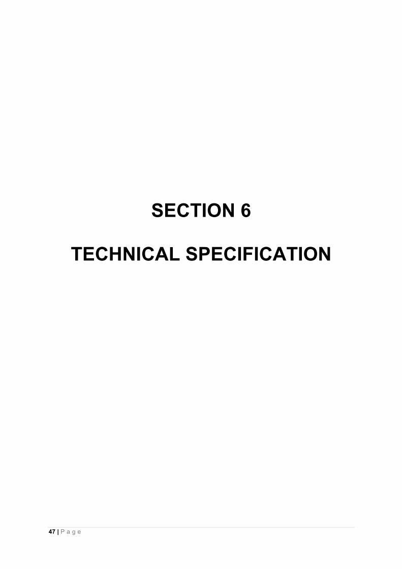
47 | P a g e
SECTION 6
TECHNICAL SPECIFICATION

48 | P a g e
CLIMATIC AND ISOCERAUNIC CONDITIONS
The climatic and isoceraunic conditions at site under which the materials /equipment shall operate satisfactorily are as follows:- a) Maximum temperature of air in shade: 40º C
b) Minimum temperature of air in shade: 2º C
c) Maximum Humidity: 93 %
d) Isoceraunic level: 60
e) Average of rainy days per annum: 150
f) Average number of days of thunderstorm per annum: 25
g) Average number of days of dust storm per annum: 10
h) Average annual rainfall: 2280 mm
i) Number of months of tropical monsoon per annum: 5 (May to Sept.)
j) Maximum wind pressure: 150Kg/sq. m.
k) Altitude (above mean sea level): 50 to 250m
The reference ambient temperatures assumed for the purpose of this specification are:
a) Maximum ambient temperature: 45ºC
b) Maximum average daily ambient temperature: 35ºC
c) Maximum average yearly ambient temperature: 30º C

49 | P a g e
1. MEDIUM VOLTAGE COVERED CONDUCTORS (MVCC)
INTRODUCTION
These Specifications lay down the Constructional, Dimensional and Performance requirements for Covered Conductors
which consist of a Conductor surrounded by a covering made of Insulating Material (as described hereunder) as protection
against accidental Contacts with other covered conductors and with grounded parts such as tree branches, etc. The
MVCC should besuitable for use under operating condition as specified below:
1. Ambient air temperature : 45°C
2. Maximum temperature of conductor at rated current : 90° C
3. Wind condition at site : 1 meter / sec
4. Solar radiation at site : 1200 watts / sq m
5. Maximum allowable temperature under Short circuit condition : 250°C
Data sheet providing details of the conductor data provided above shall be submitted along with the offer.
CONSTRUCTION REQUIREMENTS
1) CONDUCTOR
a. CONDUCTOR MATERIAL: All Aluminum Alloy (AAAC).
b. NOMINAL CROSS SECTION: 70 sq. mm for AAAC conductors.
c. CONDUCTOR DESIGN: The Conductor shall be stranded, round and should be Non Compacted.
d. Non compacted Conductors shall comply with all the requirements of EN 50397-1-2006.
e. The D.C. Resistance of the conductor shall not exceed that given in EN 50397-1-2006 by more than 5%.
2) FILLING (WATER BLOCKING)
The Stranded Conductor shall be longitudinally water tight by means of a water blocking material incorporated
during the extrusion process. The use of grease /water swellable tape / water swellable powder etc. is not
permitted. The water blocking material shall be stable at maximum operating conductor temperature of 90°C.
The final MVCC should result in a product with an advanced triple extrusion technology with improved
water blocking, semi conductive layer, XLPE insulation and an outer covering with carbon doped XLPE.
The water blocking compound shall be compatible with the conductor material as well asthe semi conducting
polymer screen layer above it and not adversely affect its electrical or mechanical properties.
3) SEMICONDUCTING SCREEN
A semi conductive polymeric screen should be applied over the filled stranded conductor to ensure a lower
voltage stress on the Insulation applied over the screen.
The thickness of the semi conductive polymeric screen should be of minimum 0.2 mm.
4) INSULATION
The Insulation should be dual layered with the Inner Layer being XLPE with a nominal thickness of 1.2 mm for
Voltages up to11 KV and 1.7 mm for 33 KV and the Outer Layer being a suitable Polymer which is UV Resistant,
Non Tracking and Erosion Resistant with a nominal wall thickness of 1.1 mm for Voltages up to 11 KV and 1.6

50 | P a g e
mm for 33 KV. The minimum combined Insulation Thickness of both Layers should be 2.3 mm for Voltages up to
22 KV and 3.0 mm for Voltages upto 33 KV minimum.
The conductor manufacturing and stranding process shall incorporate the longitudinal water blocking also.
The Semi Conducting Screen, Inner Insulation and Outer Insulation should be extruded in one step i.e. triple
extrusion to ensure a good, permanent bond between the three layers and also with the conductor.
It shall be possible to remove the Semi Conducting Screen, Inner and Outer Insulation Layers without damage to
the conductor.
Figure 1 shows the Cross Section of a Covered Conductor with AAAC Conductor and Figure 2 shows the Cross
Section of a Covered Conductor with AAAC Conductor.
FIGURE 1 (AAAC)
5) TYPE TESTS:
SN Description of Test As per standard
1 Conductor Resistance Test
EN 50397-1-2006
2 Thickness of Insulation & Covering
3 Tensile strength
4
Percentage Elongation at break of Insulation before ageing, after ageing & Completed Cable ageing
5 Carbon black content test on outer covering
6 Shrinkage test on outer covering
7 Shrinkage test on Insulation
8 Hot set test on Insulation
9 Water Absorption test on Insulation
10 Test for longitudinal water tightness
11 AC High Voltage test
12 Leakage Current Measurement
13 Tracking Resistance test
14 Slippage Test

51 | P a g e
Type test report for Covered conductors is to be submitted with the bid.
ELECTRICAL TESTS
Conductor Resistance Test: To be done as a Routine as well as Type Test as per EN 50397-1-2006.
High Voltage Test as per EN 50397-1-2006: Type test
Test Voltage: Phase to Phase Voltage of the System for which the Covered Conductor is used.
No. of Specimens:One
Length of Specimen (minimum): 5 meters
Duration of Immersion in Water (minimum): 1 Hour
Temperature of Water: (20 ± 5)° Centigrade
Test Duration:
4 Hours for Routine Test
48 Hours for Type Test
Requirement: No Breakdown
Spark Test on Covering: Routine test
Test Voltage 0.7 X Phase to Phase Voltage of System (A, C,) orPhase to Phase Voltage of System (D. C.)
Requirement: No Breakdown
Leakage Current Test - Type test
Test Voltage 0.7 X Phase to Phase Voltage of System (A. C.)
Requirement: Maximum Leakage Current 1mA
Tracking Resistance: Type test
NON – ELECTRICAL TESTS ON COVERING: Type tests
Mechanical Properties:
a) Before Ageing of Sample: As per Table 1 in accordance with EN 50397-1-2006.
b) After Ageing of Sample: As per Table 1 in accordance with EN 50397-1-2006.
c) Ageing of Complete Product Sample: As per Table 1 in accordance with EN 50397-1-2006.
d) Hot-Set-Test: As per Table 1 and in accordance with EN 50397-1-2006.
e) Pressure Test at High Temperature: As per Table 1 in accordance with EN 60811-3-1, Sub Clause 6.1.
h) Water Absorption: As per Table 1 in accordance with EN 50397-1-2006
TEST FOR LONGITUDINAL WATER TIGHTNESS
a) As Type Test with Heat Cycle and in accordance with 50397-1-2006.
No of Specimen – 1
Length of Specimen-----3 metres
Test Duration -- 24 hours
Bending Radius – 20 X Diameter of Covered Conductor

52 | P a g e
Requirement – No Leakage
b) As Routine Test without Heat Cycle and in accordance with IEC 60502 -2
No of Specimen – 1
Length of Specimen – 1 metre
Test Duration – 1 Hour
MARKING
The covered conductors shall carry the marking at regular interval as below.
a. Manufacturer name
b. Voltage Grade
c. Covered AAAC conductor
d. Conductor Size.
e. Year of Manufacturing.
f. Specification reference.
2. GALVANIZED CHANNEL CROSS ARMS
1.0 Scope
This specification covers the design, manufacture, testing at manufacturer's works, transport to site, insurance, storage, erection and commissioning of Galvanized Cross Arm and Channel used for 11 KV line complete with all accessories as specified.
2.0 Standards
The M.S Cross Arm and channel supplied under this specification shall conform to the latest issue of the relevant Indian Standards IS – 226:1975, Regulations etc. except where specified otherwise. The rolling and cutting tolerance for steel product conforming to IS: 266 shall be those specified in the IS: 1852-1973 with latest revision. Galvanization conforming to latest version of 1S:2629 or equivalent international specifications
In the event of conforming to any standards other than the Indian Standards, the salient features of comparison shall be clearly set out separately.
3.0 General Requirement :
i. The cross arm shall be fabricated grade of mild steel of channel section as per requirement. ii. All steel members and other parts of fabricated material as delivered shall be free of warps, local deformation,
unauthorized splices, or unauthorized bends. iii. Bending of flat strap shall be carried out cold. Straightening shall be carried out by pressure and not by
hammering. Straightness is of particular importance if the alignment of bolt holes along a member is referred to its edges.
iv. Holes and other provisions for field assembly shall be properly marked and cross referenced. Where required, either by notations on the drawing or by the necessity of proper identification and fittings for field assembly, the connection shall be match marked.
v. A tolerance of not more than 1mm shall be permitted in the distance between the center lines of bolt holes. The holes may be either drilled or punched and, unless otherwise stated, shall be not more than 2mm greater in diameter than the bolts.
vi. When assembling the components force may be used to bring the bolt holes together (provided neither members nor holes are thereby distorted) but all force must be removed before the bolt is inserted. Otherwise strain shall be deemed to be present and the structure may be rejected even though it may be, in all other respects, in conformity with the specification.
vii. The back of the inner angle irons of lap joints shall be chamfered and the ends of the members cut where necessary and such other measures taken as will ensure that all members can be bolted together without strain

53 | P a g e
or distortion. In particular, steps shall be taken to relieve stress in cold worked steel so as to prevent the onset of embitterment during galvanizing.
viii. Similar parts shall be interchangeable. ix. Shapes and plates shall be fabricated and assembled in the shop to the greatest extent practicable. Shearing
flame cutting and chipping shall be done carefully, neatly and accurately. Holes shall be cut, drilled or punched at right angles to the surface and shall not be made or enlarged by burning. Holes shall be clean-cut without torn or ragged edges, and burrs resulting from drilling or reaming operations shall be removed with the proper tool.
x. Shapes and plates shall be fabricated to the tolerance that will permit fielderection within tolerance, except as otherwise specified. All fabrication shall be carried out in a neat and workmanlike manner so as to facilitate cleaning, painting, galvanizing and inspection and to avoid areas in which water and other matter can lodge.
xi. Contact surfaces at all connections shall be free of loose scale, dirt, burrs, oil and other foreign materials that might prevent solid seating of the parts.
xii. Welded joints not permissible. xiii. The rolling and cutting tolerance for steel product conforming to IS: 266 shall be those specified in the IS: 1852-
1973 with latest revision. all dimensions are subject to the following tolerances: a) dimensions up to and including 50mm:+1mm: and b) dimensions greater than 50mm: +2%
xiv. The channel cross arm shall be properly brushed to make it free from rust. xv. For galvanized channel :
All ferrous parts including all sizes of nuts, bolts, plain and spring washers, support channels, structures, shall; be hot dip galvanized conforming to latest version of IS:2629 or any other equivalent standard. The zinc coating shall be smooth, continuous and uniform. It shall be free from acid spot and shall not scale, blister or be removable by handling or packing. There shall be no impurities in the zinc or additives to the galvanic bath which could have a detrimental effect on the durability of the zinc coating. Before packing, all welding, drilling, cutting, grinding and other finishing operations must be completed and all grease, paints, varnish, oil, welding slag and other foreign matter completely removed. All protuberances, which would affect the life of galvanizing shall also be removed.
The weight of zinc deposited shall be in accordance with that stated in Standard IS 2629 and shall not less than 0.61kg/m² with a minimum thickness of 86 microns for items of thickness more than 5mm, 0.46kg/m² (64 microns) for items of thickness between 2mm and 5mm and 0.33kg/m² (47 microns) for items less than 2mm thick.
xvi. The raw materials and fabrication thereof in respect of cross arm shall be furnished along with dimension. xvii. The hole for fixing of insulator and pole clamp shall be provided as per requirement. xviii. One copy of the drawing of cross arm for each size shall be furnished along with the technical bid.
REQUIRED TECHNICAL SPECIFICATION FOR GI CHANNEL CROSS ARM
(A) Sl No. Description Particular
1 Type of cross arm GI Channel cross arm 2 Size 100 x 50x 50x6 x 2200 mm 3 Material Mild Steel channel( galvanized) 4 Length 2200 mm 5 Breath 100 mm 6 Width 50 mm 7 Thickness 6 mm 8 Hole for foxing of insulator 20 mm 9 Center to center distance for hole 1070mm
10 Weight 20.5 kg (approx)
11 Galvanization The cross arm shall be properly brushed to make it free from rust and hot dip galvanized confirming to IS: 2629 or equivalent international specifications.

54 | P a g e
(B) Sl No. Description Particular
1 Type of cross arm GI Angle cross arm 2 Size 50x 50x6 mm 3 Material Mild Steel channel( galvanized) 4 Length 2200 mm 5 Breath 50 mm 6 Width 50 mm 7 Thickness 6 mm 8 Hole for foxing of insulator 20 mm 9 Center to center distance for hole 1070mm
10 Weight 20.5 kg (approx)
11 Galvanization The cross arm shall be properly brushed to make it free from rust and hot dip galvanized confirming to IS: 2629 or equivalent international specifications.
3. TECHNICAL PARICULARS OF COMPOSIT POLYMERIC DISC INSULATOR FOR 11 KV, 90 KN WITH CLAMPS, NUTS AND BOLTS
Sl. No
Description Unit 11KV , 90 KN , T& C type
1 Type of Insulator Composite polymeric Insulators
2 Standard according to which the Insulator manufacture and tested
IES-61109 with up to date amendments
3 Name of material used in manufacture Of the insulator with class/grade
Silicon/ Polyolefin material
(a) Material of core (FRP rod) ECR glass boron content free
i) E-glass or ECR- glass
ii) Boron content
(b) Material of housing & Weather sheds [ ] 36%
(c) ( material of end fitting ) Hot dip galvanized high strength steel
(d) Sealing compound for end fittings Silicon based sealants
4 Color Grey/ Red
5 Electrical characteristics
(a) Normal system voltage KV(rms ) 11 KV
(b) Highest system voltage KV(rms) 12 KV
(c) Dry power Frequency withstand voltage KV(rms ) 35 KV
(d) Wet power frequency withstand voltage KV (rms
) 35 KV
(e) Dry flashover voltage KV(rms) >35KV
(f) Wet flashover voltage KV(rms) >35KV
(g) Dry lighting impulse withstand voltage
a) Positive KV(peak) 75 KV
b)Negative KV(peak) 75KV

55 | P a g e
(h) Dry lighting impulse flashover voltage KV(peak)
c) positive 95KV
d) Negative KV(peak) 95 KV
(i) R/V at 1MHz when energized at 10KV/30KV(rms) under dry condition
Microvolt As per IES specification
(j) Creepage distance (mm) mm 320 mm
6 Mechanical characteristics
(a) Minimum failing load KN 90 KN
7 Dimension of insulator Drawing to be attached
(i) Weight Kg 0.90 Kg (Approx)
(ii) Dia of FRP rod mm 16 mm
(iii) Length of FRP rod mm drawing to be attached as per type test
(iv) Die. Of Weather sheds mm drawing to be attached as per type test
(v) Thickness of housing mm (3mm-Min)
(vi) Dry arc distance mm drawing to be attached as per type test
Dimension drawing of insulator including weight with clearances min weight enclosed
Provided
8 Method of fixing of sheds to housing (specify single moulder Modular construction moulding )
Modular Design
9 No. of Weather sheds drawing to be attached as per type test
10 Types of sheds drawing to be attached as per type test
(i) Aerodynamic Aerodynamic
(ii) With under ribs -------------------------
11 Packing details Each insulator in poly bag then packed in master carton- 7Ply
(a) Types of packing Corrugated Bodies
(b) No. of insulator each pack One master carton box containing 16Pcs
(c) Gross weight of package 17 KG ( approx. )
12 Any other particulars which the bidder may like to give
-----------------------
13 Performance Guarantee ( from date of commissioning)
18 Months
4. TECHNICAL SPECIFICATIONS FOR INSULATION PIERCING CONNECTORS SUITABLE FOR 11 KV
COVERED CONDUCTORS:
1.0 Insulation Piercing Connector having 320 AMP Current Carrying capacity with maximum Outline size in mm: 97 x 63 x
54 for 50 sq mm & 393 AMP Cu Carrying capacity with maximum Outline size in mm 131 x 82 x 57 for 99 sq mm Covered
Conductor.
2.0 Bodies of Insulation Piercing Connector shall made of glass fibre reinforced polymer having Insulated and Waterproof
seals where Insulation material should be Weather, UV and Corrosion resistant.
3.0 Insulation Piercing Connector should have Blades made of special tinned copper with End cup Design suitable for
Covered Conductor.

56 | P a g e
4.0 Insulation Piercing Connector should have Shear-head with one screw design to ensure good contact properties and
avoid damaging cables.
5.0 Insulation Piercing Connector should have Lowest Torque, easy to install & no special tools necessary to operate.
6.0 Piercing of Insulation Piercing Connector should have structural design.
7.0 Insulation Piercing Connector should have a design such that there is no stripping of insulation on the covered
conductor. It shall be able to get the Lowest contact resistance& Superior insulation as well as sealing performance.
8.0 Material of Insulation Piercing Connector should withstand for all routine & acceptance test as per NFC 33 020-1998
listed below:
a. Flashover - 15 kV for 1 min in water. b. Short circuit test, c. Mechanical test d. Heat cycle test
9.0 The superior material and process technology ensure operation regularity in corrosive environment.
10.0 Insulators, hardware fittings and other accessories.
Since the covered conductor shall be suitable for stringing overhead supported by poles / tower, the insulators such as
tension, suspension and pole top types shall be of capacity and polymeric type. They should also have enough
mechanical strength, even though the conductor span is proposed to be made somewhat loose and having shorter span
length. The insulators designed for covered conductor shall have heat & moisture resistance properties. These shall be of
type & design with proven record.
The Insulator & Hardware must have Ball & Socket or Tongue & clevis coupling as per IS: 2486 (Part-II) / IEC-60120 / IEC
60471. The Hardware materials must be confirming as per IS: 2486 and must be made of forged steel / mild steel, casting
will not be accepted. The Tension & Suspension Clamps must be of Bolted type and made of Aluminium alloy casting
conforming to A6 of IS: 617. All the ferrous parts must be hot dip galvanized except for spring washer which must be
electro galvanized. The hardware fittings to be used along with the covered conductor should have an exclusive design in
such a manner that it should never destruct the outer insulation of covered conductor while it is strung.
It shall be clearly specified how each type of the above insulators and hardware can be fixed rigidly on pole / tower. The
necessary drawings which depict the same should also be furnished.
Plastic insulator clamps/ties
The Clamps / ties shall be designed suitably to hold the MVCC in its position on top of the insulator. The Clamps is
preferred to be made of Insulating Plastic materials or protected with Insulating Plastic material to ensure tracking
resistance and to avoid any insulation damage to covered conductor due abrasion while mechanical or wind induce
vibration. For attachment of Covered Conductors (35 - 240 mm²) to pin or spool type insulators. Fixing of insulator Top
Use temperature: - 30º C to + 40º C

57 | P a g e
5. TECHNICAL SPECIFICATION FOR PSC POLES [9.75 METER]
1.0 SCOPE
This covers design manufacturing, testing at works, transport to site, insurance, storage, erection and commissioning of
PSC poles shall be of solid rectangular with an overall length of 9.75M suitable for use in overhead 11 KV lines.
2.0 Applicable Standards
The pre-stressed concrete (PSC) pole shall comply with the relevant provisions mentioned' in the' following Indian Standards or the latest versions thereof : IS: 1678, Specification for pre-stressed concrete poles for overhead power, traction and telecommunication lines. IS: 2905, Method of test for concrete poles for overhead power and telecommunication lines. IS: 7321, Code of Practice for selection, handling and erection of concrete poles for overhead power and telecommunication lines.
REQUIRED TECHNICAL PARAMETERS FOR 9.75 M PSC POLES :
3.0 Terminology
For the purpose of this specification, following definitions shall apply:
3.1Average Permanent Load
That fraction of the working load which may be considered of long duration over a period of one year.
3.2 Load Factor
The ratio of ultimate transverse load to the transverse load at first crack.
3.3 Transverse
The direction of the line bisecting the angle contained by the conductor at the pole. In the case of a straight run, this will
be normal to the run of the line.
3.4 Transverse Load at First Crack
For design, the transverse load at first crack shall be taken as not less than the value of the working load.
3.5 Working Load
The maximum load in the transverse direction, that is ever likely to occur, including the wind pressure on the pole. This
load is assumed to act at a point· 600 mm below the top with the butt end of the pole planted to the required depth as
intended in the design.
3.6 Ultimate Failure
The condition existing when the pole ceases to sustain a load increment owing to either crushing of concrete, or snapping
of the pre-stressing tendon or permanent stretching of the steel in any part of the pole.
3.7 Ultimate Transverse Load
The load at which failure occurs, when it is applied at a point 600 mm below the top and perpendicular to the axis of the
pole along the transverse direction with the butt end of the pole planted to the required depth as intended in the design.

58 | P a g e
4.0 Application (9.75 meter PSC pole)
These poles shall be used for 33 kV lines, and for special locations in 11 kV lines, such as road crossings, etc.
5.0 Material
1. Cement
The cement used in the manufacture of pre-stressed concrete poles shall be ordinary or rapid hardening Portland cement
conforming to IS: 269 (Specification for ordinary and low heat Portland cement) or IS: 8041 E (Specification for rapid
hardening Portland cement), or high strength ordinary Portland cement conforming to IS: 8112 (Specification of high
strength ordinary Portland cement).
2. Aggregates
Aggregates used for the manufacture of pre-stressed concrete poles shall confirm to IS: 383 (Specification for coarse and
fine aggregates from natural sources for concrete). The nominal maximum size of aggregates shall in no case exceed 10
mm (for poles above 9.0 M) and 12 mm (for 7.5 and 8.0 M poles).
3. Water
Water should be free from chlorides, sulphates, other salts and organic matter, Potable water will be generally suitable.
4. Addmixture
Admixture should not contain Calcium Chloride or other chlorides and salts which are likely to promote corrosion of pre-
stressing steel.
5. Pre-stressing Steel
The pre-stressing steel wires including those used as un-tensioned wires (See Annexure. I, II &III), should conform to IS:
1785 (part-I) (Specification for plain hard-drawn steel wire for pre-stressed concrete. Part-I cold drawn stress relieved
wire), IS: 1785 (part-II) (Specification for plain hard-drawn steel wire) or IS: 6003 (Specification for indented wire for pre-
stressed concrete). The type designs given in Annexure-I, II and III are for plain wires of 4 mm diameter with a guaranteed
ultimate strength of 175 kg/mm2.
The concrete mix shall be designed to the requirements laid down for controlled concrete (also called design mix
concrete) in IS: 1343 (Code of practice for pre-stressed concrete) and IS: 456 (Code of practice for plain and reinforced
concrete), subject to the following special conditions :
a. Maximum works cube strength at 28 days should be at least 400 kg/cm2 (for poles above 9.0 M) and 420
kg/cm2 (for 7.5 and 8.0 M poles).
b. The concrete strength at transfer should be at least 200 kg/cm2 (for poles above 9.0 M) ·and 210 kg/cm2 (for
7.5 and 8.0 M poles).
c. The mix should contain at least 380 kg of cement per cubic meter of concrete.
d. The mix should contain as low a water content as is consistent with adequate workability. If it becomes
necessary to add water to increase the workability, the cement content also should be raised in such a way that
the original value of water cement ratio is maintained.

59 | P a g e
6. DESIGN REQUIREMENTS
The poles shall be designed for the following requirement : a. The poles shall be planted directly in the ground with a planting depth as per IS: 1678. b. The working load on the poles should correspond to those that are likely to come on the pole during their service life. Designs given in Annexure I, II and III are for 140 kg, 200 kg, 300 kg, and 400 kg., applied at 0.6 M from top. c. The factor of safety for all poles above 9.5 M shall not be less than 2.0. For 7.5 M and 8.5 M poles, the factor of safety shall not be less than 2.5. d. The average permanent load shall be 40% of the working load. e. The F.O.S. against first load shall be 1.0.
f. At average permanent load, permissible tensile stress in concrete shall be 30 kg/cm2.
g. At the design value of first crack load, the modulus of rupture shall not exceed 53.0 kg/cm2 for M-400
concrete and 55.2 kg/cm2 for M-420 concrete.
h. At the design value of first crack load, the modulus of rupture shall not exceed 53.0 kg/cm2 for M-400
concrete.
i. The ultimate moment capacity in the longitudinal direction should be at least one fourth of that il1 the
transverse direction.
j. The maximum compressive stress in concrete at the time of transfer of pre-stress should not exceed 0.8 times
the cube strength.
k. The concrete strength at transfer shall not be less than half the 28 days strength ensured in the design, i.e.,
400 x 0.5 = 200 kg/cm2 or 420 x 0.5 = 210 kg/cm2.
7. Service Conditions
PSC poles have to be designed to suit the following climatic conditions:
a) Maximum temperature of air in shade 40°C b) Minimum temperature of air in shade 2°C
c) Maximum temperature of air in sun 45°C
d) Maximum humidity 93%
e) Average number of thunder storm days per 45 Days
annum f) Maximum rainfall per annum 3500 mm
g) Average rainfall per annum 2200 mm
h) Wind pressure 97.8 Kg/m2
i) Altitude above MSL to 1000 M
8. Dimensions and Reinforcements
The cross-sectional dimensions and the details of pre-stressing wires should conform to the particulars given in Annexure-
I, II and III.
The provisions of holes for fixing cross-arms and other fixtures should conform to the REC standards .

60 | P a g e
9. Manufacture
Attire--stressing wires and reinforcements shall be accurately fixed as shown in drawings and maintained in position
during manufacture. The un-tensioned reinforcement, as indicated in the drawings, should be held in position by the use
of stirrups which should go round all the wires.
All wires shall be accurately stretched with uniform pre-stress in each wire. Each wire or a group of wires shall be
anchored positively during casing. Care should be taken to see that the anchorages do not yield before the concrete
attains the necessary strength.
10. Cover
The cover of concrete measured from the outside of pre-stressing tendon shall be normally 20 Nm.
11. Welding and Lapping of Steel
The high tensile steel wire shall be continuous over the entire length of the tendon. Welding shall not be allowed in any
case. However, jointing or coupling may be permitted provided the strength of the joint or coupling is not less than the
strength of each individual wire.
12. Compacting
Concrete shall be compacted by spinning, vibrating, shocking or other suitable mechanical means. Hand compaction shall
not be permitted.
13. Curing
The concrete shall be covered with a layer of sacking, canvass, Hessian or similar absorbent material and kept constantly
wet up to the time when the strength of concrete is at least equal to the minimum strength of concrete at transfer of pre-
stress. Thereafter, the pole may be removed from the mould and watered at intervals to prevent surface cracking of the
unit, the interval should depend on the atmospheric humidity and temperature.
The pre-stressing wires shall be de-tensioned only after the concrete has attained the specified strength at transfer (i.e.,
200 or 210 kg/cm2 as applicable). The cubes cast for the purpose of determining the strength at transfer should be cured,
as far as possible, under conditions similar to those under which the poles are cured. The transfer stage shall be
determined based on the daily tests carried out on concrete cubes till the specified strength indicated above is reached.
Thereafter the test on concrete shall be carried out as detailed in IS: 1343 (Code of pr3ctice for pre-stressed concrete).
The manufacturer shall supply, when required by the owner or his representative, result of compressive test conducted in
accordance with IS: 456 (Code of practice for plain and reinforced concrete) on concrete cubes made from the concrete
used for the poles. If the owner so desired, the manufacturer shall supply cubes for test purposes and such cubes shall be
tested in accordance with IS: 456 (Code of practice for plain and reinforced concrete).
The de-tensioning shall be done by slowly releasing the wires, without imparting shock or sudden load to the poles. The
rate of de-tensioning may be controlled by any suitable means either mechanical (screw type) or hydraulic.

61 | P a g e
The poles shall not be de-tensioned or released by cutting the pre-stressing wires using flames or bar croppers while the
wires are still under tension.
Separate eye-hooks or holes shall be provided for handling the transport, one each at a distance of 0.15 times the overall
length, from either end of the pole. Eye-hooks, if provided, should be properly anchored and should be on the face that
has the shorter dimension of the cross-section. Holes, if provided for lifting purposes, should be perpendicular to the
broad face of the pole.
Stacking should be done in such a manner that the broad side of the pole is vertical. Each tier in the stack should be
supported on timber sleeper located as 0.15 times the overall length, measured from the end. The timber supported in the
stack should be aligned in a vertical line.
Poles should be transported with their broad faces placed vertically and, in such a manner that the shocks are avoided.
Supports should be so arranged that they are located approximately at a distance equal to 0.15 times the overall length
from the ends. The erection of the pole should be carried out in such a way that the erection loads are applied so as to
cause moment with respect to the major axis, i.e., the rope used for hoisting the pole should be parallel to the broader
face of the pole.
14. Earthing
14.1 Earthing shall be provided by having length of 8 SWG GI wire embedded in concrete during manufacture and the
ends of the wires left projecting from the pole to a length of 100 mm at 250 mm from top and 150 mm below ground level.
14.2 Earth wire shall not be allowed to come in contract with the pre-stressing wires.
15. Transverse Strength Test
Poles made from ordinary Portland cement shall be tested only on the completion of 28 days and poles made from rapid
hardening cement only on the completion of 14 days, after the day of manufacture.
The poles may be tested in either horizontal or vertical position. If tested in horizontal position, provisions shall be made to
compensate for the overhanging weight of the pole, for this purposed, the overhanging portion of the pole may be
supported on a movable trolley or similar device.
The pole shall be rigidly supported at the butt end for a distance equal to the agreed depth of planting.
Load shall be applied at a point 600 mm from the top of the pole and shall be steadily and gradually increased to the
design value of the transverse load at first crack. The deflection at this load shall be measured.
A pre-stressed concrete pole shall be deemed not to have passed the test if visible cracks appear at a stage prior to the
application of the design transverse load for the first crack.
The load shall then be reduced to zero and increased gradually to a load equal to the first crack load plus 10% of the
minimum ultimate transverse load, and held up for 2 minutes. This procedure shall be repeated until the load reaches the
value of 80 per cent of the minimum ultimate transverse load and thereafter increased by 5 per cent of the minimum
ultimate transverse load until failure occurs. Each time the load is applied, it shall be held for 2 minutes. The load applied
to pre-stressed concrete pole at the point of failure shall be measured to the nearest five kilograms.
The pole shall be deemed not to have passed the test if the observed ultimate transverse load is less than the design
ultimate transverse load.
62 | P a g e
16. Measurement of Cover
After completion of the transverse strength test, the sample pole shall be taken and checked for cover. The cover of the
pole shall be measured at 3 points, one within 1.8 meter from the butt end of the pole. the ·second within 0.6 meters from
the top and the third at an intermediate point and the mean value compared with the specified value.
The mean value of the measured cover should not differ by more than (±) 1 mrn from the specified cover. The individual
values should not differ by more than (±) 3 mm from the specified value.
If these requirements are not met, the workmanship with reference to aligning of the end plates and pre-stressing wires
and assembly of moulds should be improved and inspection at pre-production stage tightened suitably.
17 Marking
The pole shall be clearly and indelibly marked with the following particulars either during or after manufacture but before
testing at a position so as to be easily read after erection in position.
Month and year of manufacture
Transverse strength of pole in Kg
Maker's serial no. and mark and Project.
18. Inspection
Inspection may be carried out by the purchaser or third party nominee at any stage of manufacture. The supplier shall
grant free access to the purchaser's representative or third party nominee at a reasonable time when the work is in
progress. Inspection and acceptance of any equipment under this specification by the purchaser shall not relieve the
supplier of his obligation of furnishing equipment in accordance with the specification and shall not prevent subsequent
rejection if the equipment is found defective.
SL ITEM
1 Type of Pole 9.75 M PSC pole
3 Length of pole 9.75 Mts.
4 Depth of Plantation 1.8 Mts.
5 Bottom Depth 350 mm
6 Top Depth 175 mm
7 Breath 120 mm
8 Diameter of pre-stressing wire 4 mm
9 No. of tensioned wire per pole 22 Nos of 4mm dia.
10 Minimum Ultimate Tensile strength of 4 mm.
HT wire
175 KG / SQMM
11 Minimum initial pull of 4 mm wire 1865 kg / wire
12 Spacing HT wires As per IS : 1343 /1960
13 Quantity of HT wire/ pole 21.45 KG
14 Link & spiral 3.540 KG ( 4 nos ,5 mm in bottom & 4 nos ,5 mm in
top
15 M.S spiral 3 mm dia of 150 c/c
16 Maximum Aggregate size 12 mm

63 | P a g e
17 Total weight per pole 750 KG
18 Minimum clear cover 20 mm
19 Factor of safety 2.5
20 Concrete grade M-420
21 Ultimate Load 675 KG
22 Earthing shall be provided by 4 MM dia.
Galvanized iron wire embedded in
concrete
Projecting from the pole at length of 50 MM at 215
from top & 150 MM below ground level
23 one marks to be provided at ground level at 1.8 M
24 28 days cube strength of concrete (min)
as per IS : 456/2000.
420 Kg / sq.cm.
6. TECHNICAL SPECIFICATION FOR STAY SET (HT)
1. Scope:
This specification covers the design, manufacture testing at manufacturer's works, transport to site, insurance, storage, erection and commissioning of the Stay Sets (HT) required from the distribution lines at designated locations.
2.0 Standard: All the materials of stay sets shall comply in all respects with the requirements of the latest edition of the relevant Indian or British Standard specification except in so far as they are modified this specification.
3.0 Design Consideration: Stay Rods shall be Galvanized and shall be of circular Cross-section with bow, thimble, nuts and bolts. The Rods shall be threaded at one end up to a minimum of 30 cm length and shall be complete with Galvanized M.S. Anchor Plates with all necessary accessories. All parts shall be heavily galvanized.
4.0 Testing: Type and Routine Tests should be carried on different components of each stay sets as per relevant Indian Standard specification and certified copies of the above should be submitted along with the tender.
5.0 Schedule Requirement:
Stay sets complete with Thimble bow stay Rod/Anchor plate with nuts etc. and made of Rolled mild Steel Rod and plates as per detailed given below:
A) Anchor Plate: II) Thickness not below 5 mm. III) Size not below 300 mmX300 mm with smooth edges (for HT) IV) Well galvanized V) Materials M.S. Rolled plate VI) About 20 mm square hole at centre for locking the plate with the Anchor Rod (for HT)
A) Anchor Rod: 2.1 Length 1800 mm or above 2.2 Threaded length 30 cm or above

64 | P a g e
2.3 Diameter 18 mm or above (for HT) 2.4 Anchor plate and head: square size 30mm X 30mm with thickness 25 mm having matching
square size shank for locking the Anchor plate. 2.5 One ratched lock nuts, grooves must match the grooves at bow flange 2.6 One check nut. 2.7 Materials H.S. 2.8 Component well galvanized with extra care for the threaded portion. 2.9 Both lock and check nuts should be matching to the Anchor Rod thread such that punching of
thread after assembly at site safeguards them against removal.
B) Thimble: The match bow diameter and bend should be well galvanized. C) Bow: Rod diameter 12mm/16mm or above overall length 35cm/40cm or above. Flange with well formed
locking grooves matching the locking nut, bow ends will be riveted securely with the flange. All items to be galvanized.
6.0 Inspection:
All tests and inspections shall be carried out at the place of manufacturer unless otherwise agreed by the purchaser and the manufacturers at the time of purchase. A manufacturer shall afford the inspector representing the purchaser or third party nominee, all reasonable facilities, without charge to satisfy that the materials are being purchased as per specification. The purchaser reserves the right to have the test carried out at his cost by an independent agency, whenever there is dispute regarding the quality of the materials supplied.
7.0 Marking The equipments shall be marked with name of manufacturer, year and name of project.
7. TECHNICAL SPECIFICATION FOR G.I. STAY WIRE 1.0 Scope :The specification covers design, manufacturing and testing, transporting to site, insurance,
storage, erection and commissioning of G.I. Stay Wire 7/10SWG and 7/14SWG.
2.0 Materials. The wire shall be manufactured from steel, made by any suitable process and shall not contain sulphur and phosphorus exceeding 0.065 percent each.
The wires shall be coated with Zinc Grade Zn 98 of IS:209-1966 The general requirements for the supply of Galvanized stay strand shall be in accordance with IS:1387-1967
3.0 Construction 3.1 Grades: The wire shall be of Grade-I and tensile strength range 45 up to and including Kg/mm 3.2 The Galvanized stay strand shall be of 7/2 mm and 7/3.15 mm. the lay of the strands shall be of the length of 7/2
mm and Tables-I of IS: 2141-1963. the wires shall be so stranded together that when and evenly distributed pull is applied at the end of the completed strand each wire will take equal share of the pull.
3.3 The length of the strand which may be supplied without joints in the individual wires comprising it, depend on the length of wire which may be carried by the bobbin in a normal stranding machine. The normal lengths of strand which shall be supplied without joints in the individual wires, excluding welds made in the rod before drawing shall be as given below. The lengths may be exceeded by agreement between the manufacturer and the purchaser.
Diameter of wire in strand Normal length without joints of weld 3.15 mm 1000 M 2.0 mm 3000 M
3.4 In cases where joints are permitted, they shall be made by welding of brazing joints in the same wire shall be separated by a length of not less than that shown in 3.3 and joints in different wires in a strand shall not be less than 20 M apart.
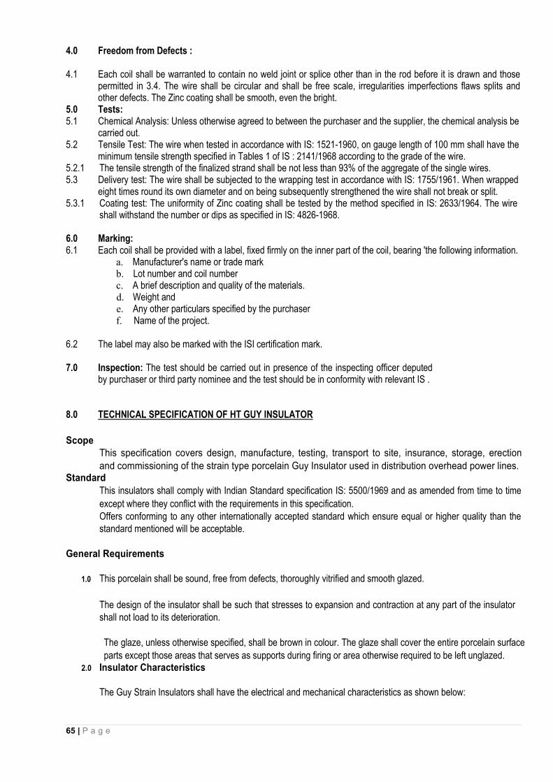
65 | P a g e
4.0 Freedom from Defects : 4.1 Each coil shall be warranted to contain no weld joint or splice other than in the rod before it is drawn and those
permitted in 3.4. The wire shall be circular and shall be free scale, irregularities imperfections flaws splits and other defects. The Zinc coating shall be smooth, even the bright.
5.0 Tests: 5.1 Chemical Analysis: Unless otherwise agreed to between the purchaser and the supplier, the chemical analysis be
carried out. 5.2 Tensile Test: The wire when tested in accordance with IS: 1521-1960, on gauge length of 100 mm shall have the
minimum tensile strength specified in Tables 1 of IS : 2141/1968 according to the grade of the wire. 5.2.1 The tensile strength of the finalized strand shall be not less than 93% of the aggregate of the single wires. 5.3 Delivery test: The wire shall be subjected to the wrapping test in accordance with IS: 1755/1961. When wrapped
eight times round its own diameter and on being subsequently strengthened the wire shall not break or split. 5.3.1 Coating test: The uniformity of Zinc coating shall be tested by the method specified in IS: 2633/1964. The wire
shall withstand the number or dips as specified in IS: 4826-1968.
6.0 Marking: 6.1 Each coil shall be provided with a label, fixed firmly on the inner part of the coil, bearing 'the following information.
a. Manufacturer's name or trade mark b. Lot number and coil number c. A brief description and quality of the materials. d. Weight and e. Any other particulars specified by the purchaser f. Name of the project.
6.2 The label may also be marked with the ISI certification mark.
7.0 Inspection: The test should be carried out in presence of the inspecting officer deputed by purchaser or third party nominee and the test should be in conformity with relevant IS .
8.0 TECHNICAL SPECIFICATION OF HT GUY INSULATOR
Scope This specification covers design, manufacture, testing, transport to site, insurance, storage, erection
and commissioning of the strain type porcelain Guy Insulator used in distribution overhead power lines. Standard
This insulators shall comply with Indian Standard specification IS: 5500/1969 and as amended from time to time
except where they conflict with the requirements in this specification. Offers conforming to any other internationally accepted standard which ensure equal or higher quality than the standard mentioned will be acceptable.
General Requirements
1.0 This porcelain shall be sound, free from defects, thoroughly vitrified and smooth glazed.
The design of the insulator shall be such that stresses to expansion and contraction at any part of the insulator shall not load to its deterioration.
The glaze, unless otherwise specified, shall be brown in colour. The glaze shall cover the entire porcelain surface
parts except those areas that serves as supports during firing or area otherwise required to be left unglazed. 2.0 Insulator Characteristics
The Guy Strain Insulators shall have the electrical and mechanical characteristics as shown below:
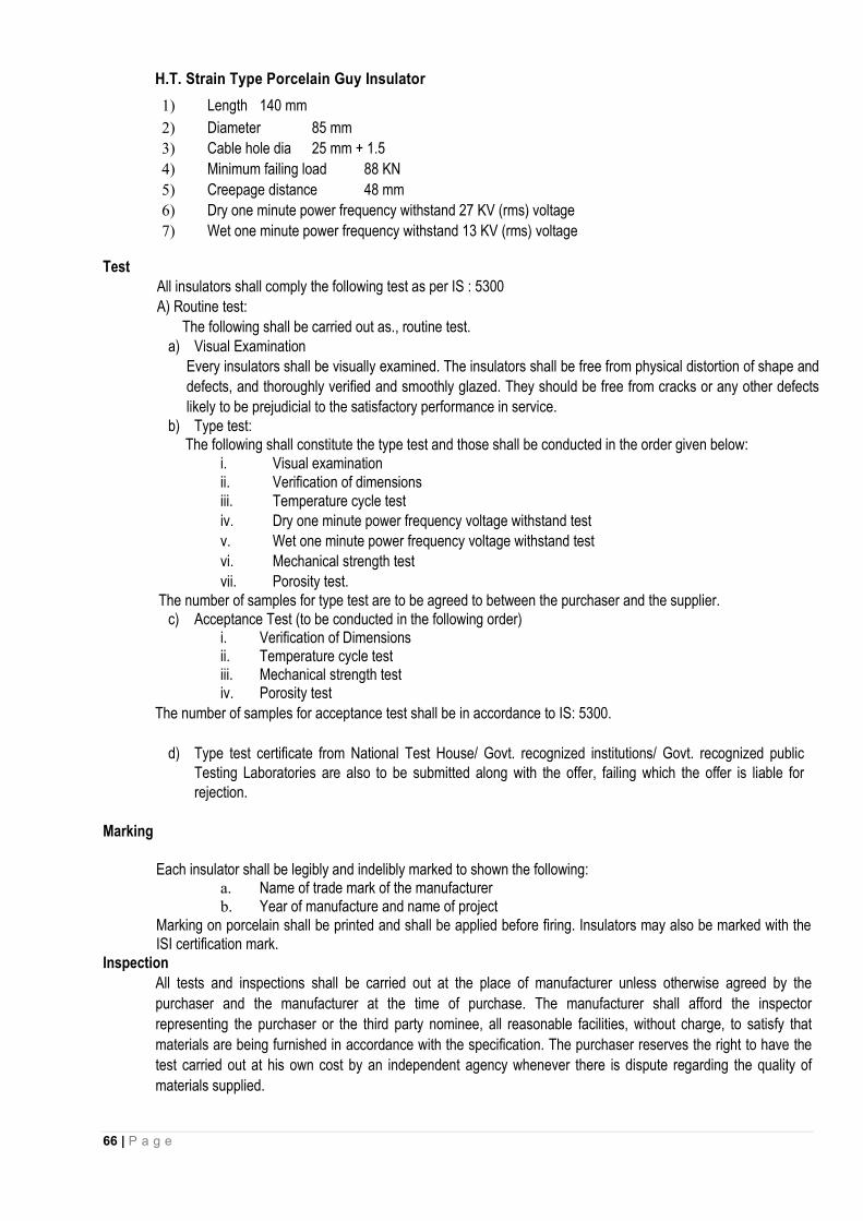
66 | P a g e
H.T. Strain Type Porcelain Guy Insulator
1) Length 140 mm
2) Diameter 85 mm
3) Cable hole dia 25 mm + 1.5
4) Minimum failing load 88 KN
5) Creepage distance 48 mm
6) Dry one minute power frequency withstand 27 KV (rms) voltage
7) Wet one minute power frequency withstand 13 KV (rms) voltage Test
All insulators shall comply the following test as per IS : 5300
A) Routine test:
The following shall be carried out as., routine test. a) Visual Examination
Every insulators shall be visually examined. The insulators shall be free from physical distortion of shape and
defects, and thoroughly verified and smoothly glazed. They should be free from cracks or any other defects
likely to be prejudicial to the satisfactory performance in service. b) Type test:
The following shall constitute the type test and those shall be conducted in the order given below: i. Visual examination ii. Verification of dimensions iii. Temperature cycle test iv. Dry one minute power frequency voltage withstand test
v. Wet one minute power frequency voltage withstand test
vi. Mechanical strength test
vii. Porosity test. The number of samples for type test are to be agreed to between the purchaser and the supplier.
c) Acceptance Test (to be conducted in the following order) i. Verification of Dimensions ii. Temperature cycle test iii. Mechanical strength test iv. Porosity test
The number of samples for acceptance test shall be in accordance to IS: 5300.
d) Type test certificate from National Test House/ Govt. recognized institutions/ Govt. recognized public
Testing Laboratories are also to be submitted along with the offer, failing which the offer is liable for rejection.
Marking
Each insulator shall be legibly and indelibly marked to shown the following: a. Name of trade mark of the manufacturer b. Year of manufacture and name of project
Marking on porcelain shall be printed and shall be applied before firing. Insulators may also be marked with the ISI certification mark.
Inspection
All tests and inspections shall be carried out at the place of manufacturer unless otherwise agreed by the
purchaser and the manufacturer at the time of purchase. The manufacturer shall afford the inspector
representing the purchaser or the third party nominee, all reasonable facilities, without charge, to satisfy that
materials are being furnished in accordance with the specification. The purchaser reserves the right to have the
test carried out at his own cost by an independent agency whenever there is dispute regarding the quality of
materials supplied.

67 | P a g e
3.0 Drawing Drawing specifically showing all dimensions is to be submitted along with technical bid.
9. TECHNICAL SPECIFICATION FOR CAST IRON EARTH PIPE
1.0 Scope
This specification covers design, manufacture, testing, transport to site, insurance, storage, erection and commissioning of the cast iron earth pipe for use on line &substation as earthing pipe
2.0 Standard The Earth pipe shall comply with the Indian Standard specification IS: 1729/1964 and as amended from time to time except where they conflict with the specific requirements in this specification.
3.0 Manufacture
Metal used for the manufacture of pipes shall be good quality cast iron. Casting shall be stripped with all precautions necessary to avoid wrapping and shrinkage defects. They shall be free from defects which effect the use of castings. By agreement between the purchaser and the manufacturer, minor defects may be rectified. Pipes shall be such that they could be cut, drilled or machines. Bolts, buts &washers shall be made of Steel and well galvanized. The bolts shall be of 200 mm length, 16 mm diameter with 2(two) nos. plain washers, one locknut &one check nut. Threaded length of the bolts should be 50 mm.
4.0 Sizes
Dimensions of pipe &socket shall be conform to the sizes shown below and as per drawing enclosed:
Nominal length of the pipe with socket 1800 mm Nominal diameter of pipe 100 mm External diameter of pipe 110 mm Thickness of pipe 5 mm Projection of spigot bead 3 mm Width of spigot bead 15 mm Internal dia of socket 129 mm Thickness of socket 6 mm Internal depth of socket 70 mm Internal Radius of socket 5 mm Width of grooves of socket 10 mm External dia of grooves socket 155 mm Depth of grooves of socket 5 mm Nominal weight of pipe (Exclusive of ear) 21.67 Kg
5.0 Tolerance The Tolerance of the 100 mm nominal diameter pipe shall be ±3.5 mm
The Tolerance of pipe thickness shall be - 15 percent The Tolerance of length of the pipe shall be - ± 20mm The Tolerance of weight of the pipe shall be - 10 Percent
Pipes weighing more than the nominal weight may be accepted provided they comply in every other respect with the requirements of this standard.

68 | P a g e
6.0 TEST 8.1 Hammer test: Each pipe when tested for soundness by striking with a light hand hammer shall emit a clear ringing
sound.
8.2 Hydraulic test : If so required by the purchaser, pipe shall be tested hydraulically at a pressure of 0.4 kg/cm2without showing any sign of leakage, sweating or other defect of any kind. The pressure shall be applied internally and shall be maintained for not less than 15 seconds. The tests shall be conducted before coating of pipe.
9.0 Inspection
All tests and inspection shall be carried out at the place of manufacturers unless otherwise agreed by the purchaser and the manufacturer at the time of purchase. A manufacturer shall afford the inspector representing the purchaser or third party nominee all reasonable facilities without charge to satisfy that the materials are being purchased as per specification. The purchaser reserves the right to have the test carried out at his cost by an independent agency, whenever there is dispute regarding the quality of materials supplied. All incoming consignment shall be checked at stores.
10.0 Coating
Normally pipes, unless specially ordered, shall be supplied free of coating on surfaces.
11.0 Marking
Each pipe shall have the Trade mark of the manufacturer and nominal size suitably marked on it. The pipe marked with the ISI certificate mark, shall be preferred. The equipments shall be marked with name of manufacturer, year and name of project.
10. TECHNICAL SPECIFICATION FOR G.I. WIRE
1.0 Scope This specification covers the manufacturing, testing at works, transport to site, insurance, storage,
erection and commissioning of Galvanized Iron Wire of sizes 4 mm and 5 mm diameter.
2.0 General requirements It relating to the supply of mild steel wire shall be as per IS: 1387/1967 and the wire
shall be drawn from the wire rods conforming to IS: 7887/1975.
The requirements for chemical composition for the wires shall conform to IS:7887/1975.
Mild steel wire for General Engineering purpose shall be of following sizes:
I) 4mm - diameter (8 SWG)
II) 5mm - diameter (6 SWG) Tolerance permitted on the diameter of wire shall be as per Table -1 of IS:280/1978.
3.0 Climatic Conditions The cross arms should be suitable for the climatic condition mentioned In these bidding
documents:
4.0 Mechanical Properties 4.1 Tensile Test: Tensile strength of wire when tested in accordance with IS:
1521-1972, shall be within the limits given in Table-2 of IS: 280/1978.
4.2 Wrapping Test: Wires shall be subjected wrapping test in accordance with IS: 1755-1961. The wire shall
withstand without breaking or splitting. being wrapped eight times round its own diameter and subsequently
straightened.
Surface finish a. The wire shall have galvanized finishes. The galvanized coating of steel wire shall conform to the requirements
for anyone of the types of coatings given in IS: 4826-1968 as per agreement with the purchaser.

69 | P a g e
b. The coating test for finishes other than galvanized, copper coated or tinned shall be subject to between the purchaser and the manufacturer.
c. Unless otherwise agreed to the method of drawing representative samples of the material and the criteria for conforming shall be as prescribed in Appendix (A) of IS: 280/1978.
d. All finished wires shall be well and cleanly drawn to the dimensions specified. The wire shall be sound, free from splits, surface flaws, rough jagged and imperfect edges and other harmful surface defects.
e. Each coil of wire shall be suitably bound and fastened compactly and shall be protected by suitably wrapped.
5.0 Marking Each coil of wire shall be marked legibly with the finish size of wire, lot number and trade mark of the
name of the manufacturer. The material may also be marked with the ISI certification mark and name of the
project.
6.0 INSPECTION: Inspection may be carried out by the purchaser or third party nominee at any stage of
manufacture. The supplier shall grant free access to the purchaser's representative or third party nominee at a
reasonable time when the work is in progress. Inspection and acceptance of any equipment under this
specification by the purchaser shall not relieve the supplier of his obligation of furnishing equipment in
accordance with the specification and shall not prevent subsequent rejection if the equipment is found defective.
11. TECHNICAL SPECIFICATION FOR DANGER NOTICE PLATE 11 kV
1.0 SCOPE:
This specification covers Danger Notice Plates to be displayed in accordance with rule No.35 of Indian Electricity Rules, 1956.
2.0 APPLICABLE STANDARDS.
Unless otherwise modified in this specification, Danger Notice [Plates shall comply with IS:-1982 or the latest version thereof.
3.0 DIMENSIONS.
Size of Danger Notice Plates as follows are recommended For display at 33KV installation - 250 x 200 mm.
The comers of the plate shall be rounded off. The location of fixing holes as shown in Figs. 1 to 4 is provisional and can be modified to suit the requirements at site.
4.0 LETTERINGS All letterings shall be centrally spaced. The dimensions of the letters, figures and their respective
position shall be as shown in figs. 1 to 4. The size of letters in the words in each language and spacing between them shall be so chosen that these are uniformly written in the space earmarked for them.
5.0 LANGUAGES
I. Under Rule No. 35 of Indian Electricity Rules, 1956, the owner of every medium, and extra high voltage installation is required to affix permanently in a conspicuous position a danger notice in Hindi or English and in addition, in local language, with the sign of skull and bones.
II. The type and size of lettering to be done in Hindi is indicated in the specimen danger notice plates shown in fig: 2 and 4 and those in English are shown in fig. 1 and 3.
III. Adequate space has been provided in the specimen danger notice plates for having the letterings in local language for the equivalent of Danger, 11000 ‘Volts’

70 | P a g e
6.0 MATERIAL AND FINISH
The plate shall be made from mild sheet of at least 1.6 mm thick and vitreous enameled white, with letters, figures and the conventional skull and cross-bones in signal red colour (refer 1S: 5-1978) on the front side. The rear side of the plate shall also be enameled.
7.0 TESTS.
The following tests shall be carried out. i) Visual examination as per 18:2551-1982. ii) Dimensional check as per IS: 2551-1982. iii) Test for weather proofness as per IS: 8709-1977 (or its latest version).
8.0 MARKING.
Maker's name and trade mark and the purchaser's name shall be marked in such a manner and position on the plates that it does not interfere with the other information.
11kV VOLTAGE CLASS SURGE ARRESTORS
INTRODUCTION
This section covers the specification of 11kV voltage station Surge Arrestors for installation on outdoor type 11kV
switchgear, transmission lines, transformers etc. 11kV side of which is not enclosed in a cable box. Station class
surge arrestors shall be complete with fasteners for stacking units.
STANDARDS
The design, manufacture and performance of Surge Arrestors shall comply with IS: 3070 Part-3 and other specific
requirements stipulated in the specification. Unless otherwise specified, the equipment, material & processes
shall conform to the latest amendments of the following:
IS:2071-1993 (Part-1) Methods of High Voltage Testing General Definitions & Test Requirements.
IS:2071-1974 (Part-2) Test Procedures.
IS: 2629-1985 Recommended Practice for hot dip galvanizing on Iron & Steel.
IS: 2633-1986 Method for Testing uniformity of coating of zinc coated Articles.
IS:3070-1993 (Part – 3) Specification for surge arrestor for alternating current systems. Metal-Oxide
lightening Arrestors without gaps.
IS: 4759-1996 Specification for hot dip zinc coating on structural steel and other allied
products.
IS: 5621-1980 Hollow Insulators for use in Electrical Equipment.
IS: 6209-1982 Methods of Partial discharge measurement.
IS: 6745 Method for determination of mass of zinc coating on zinc coated iron and steel
articles.
ANSI/IEEE-C.62.11 Metal oxide, Surge Arrestor for AC Power Circuits.
IEC –60099-4 Surge Arrestors.

71 | P a g e
The equipment complying with any other internationally accepted standards shall also be considered if it
ensures performance equivalent to or superior to the Indian Standards.
III. GENERAL REQUIREMENT
(i) The metal oxide gap less Surge Arrestor without any series or shunt gap shall be suitable for protection of 11 kV
side of power transformers, associated equipment and 11kV lines from voltage surges resulting from natural
disturbance like lightning as well as system disturbances.
(ii) The surge arrestor shall draw negligible current at operating voltage and at the same time offer least
resistance during the flow of surge current.
(iii) The surge arrestor shall consist of non-linear resistor elements placed in series and housed in electrical grade
porcelain housing / silicon polymeric of specified Creepage distance.
(iv) The assembly shall be hermetically sealed with suitable rubber gaskets with effective sealing system
arrangement to prevent ingress of moisture.
(v) The surge arrestor shall be provided with line and earth terminals of suitable size. The ground side terminal of
surge arrestor shall be connected with 25x6 mm galvanized strip, one end connected to the surge
arrestor and second end to a separate ground electrode. The bidder shall also recommend the procedure
which shall be followed in providing the earthing system to the Surge Arrestor.
(vi) The surge arrestor shall not operate under power frequency and temporary over voltage conditions but under
surge conditions, the surge arrestor shall change over to the conducting mode.
(vii) The surge arrestor shall be suitable for circuit breaker performing 0-0.3 min-CO-3 min-CO- duty in the system.
(viii) Surge arrestors shall have a suitable pressure relief system to avoid damage to the porcelain/ silicon
polymeric housing and providing path for flow of rated fault currents in the event of arrestor failure.
(ix) The reference current of the arrestor shall be high enough to eliminate the influence of grading and stray
capacitance on the measured reference voltage.
(x) The Surge Arrestor shall be thermally stable and the bidder shall furnish a copy of thermal stability test with the
bid.
(xi) The arrestor shall be capable of handling terminal energy for high surges, external pollution and transient over
voltage and have low losses at operating voltages.
(xii) The surge arrestor shall be provided with line and earth terminals of suitable size.
IV. ARRESTOR HOUSING
(i) The arrestor housing shall be made up of silicon polymeric housing and shall be homogenous, free from
laminations, cavities and other flaws of imperfections that might affect the mechanical and dielectric quality. The
housing shall be of uniform Grey (for silicon polymeric) colour, free from blisters, burrs and other similar
defects.
Arrestors shall be complete with fasteners for stacking units together and terminal connectors.

72 | P a g e
(ii) Thehousing shall be so coordinated that external flashover shall not occur due to application of any impulse or
switching surge voltage upto the maximum design value for arrestor. The arrestors shall not fail due to
contamination. The 11kV arrestors housing shall be designed for pressure relief class as given in Technical
Parameters of the specification.
(iii) Sealed housings shall exhibit no measurable leakage.
V. SURGE MONITOR :A self-contained discharge counter suitably enclosed for outdoor use and requiring no
auxiliary or battery supply for operation shall be provided for each single pole unit.Leakage current meter with
suitable scale range to measure leakage current of surge of surge arrestor shall also be supplied within the same
enclosure.The number of operations performed by the arrestor shall be recorded by the suitable cyclometric
counter and surge monitor shall be provided within the inspection window.There shall be a provision for putting
ammeter to record the current/alarm contacts in the control room if the leakage current exceeds the permitted
value.Similar provision shall be considered for the surge counter also..Surge monitor shall be mountrd on the
support structure at a suitable height so that the raeding can be taken from the ground level through the
inspection window and length connecting leads up to grounding point for 11kV class only.
VI. ARRESTOR MOUNTING
The arrestors shall be suitable for mounting on 4 pole/2 pole structure used for pole/plinth mounted transformer
and for incoming and outgoing lines. Arrestor may also be required to be mounted on a bracket provided in the
Transformers.
VII. FITTINGS & ACCESSORIES
(i) The surge arrestor shall be complete with fasteners and terminal connectors.
(ii) The terminals shall be non-magnetic, corrosion proof, robust and of adequate size and shall be so located that
incoming and outgoing connections are made with minimum possible bends. The top metal cap and base of
surge arrestor shall be galvanized. The line terminal shall have a built in clamping device which can be adjusted
for both horizontal and vertical take off.
VIII. TESTS
(i) Test on Surge Arrestors
The Surge Arrestors offered shall be type tested and shall be subjected to routine and acceptance tests in
accordance with IS : 3070 (Part-3)-/IEC:600994. In addition, the suitability of the surge arresters shall also be
established for the following :
i) Acceptance tests :
a) Measurement of power frequency reference voltage of arrester units. b) Lightning impulse residual voltage on arrester units (IEC clause 6.3.2). c) Internal ionization or partial discharge test

73 | P a g e
ii) Special Acceptance tests : a) Thermal stability test (IEC clause 7.2.2). b) Watt loss test.
iii) Routine tests : a) Measurement of reference voltage. b) Residual voltage test of arrester unit. c) Internal ionization or partial discharge test. d) Sealing test. e) Verticality check on completely assembled surge arresters as a sample test on each lot
ifapplicable.
iv) Type Tests :
Following shall be type test as per IS 3070 (Part 3): 1993 or its latest amendment :
1. Insulation Withstand test
a) Lightning Impulse
2. Residual Voltage Test
a) Steep current impulse residual voltage test
b) Lightning impulse residual voltage test
3. Long duration current impulse withstand test
4. Switching surge operating duty test
5. Power frequency voltage Vs. Time characteristics
Accelerated Ageing test
7. Pressure relief test
a) High Current
b) Low Current 8. Artificial pollution test (for porcelain housing)
9. Seismic Test
10. Partial Discharge test
11. Bending test
12. a) Temperature cycle test (for porcelain housing)
b) Porosity test (for porcelain housing) 13. Galvanising test on metal parts
14. Seal Leakage test (for porcelain housing)
15. Seal leak test and operation tests ( for surge monitor)
16. Weather ageing test (for polymer housing)
(ii) The maximum residual voltages corresponding to nominal discharge current of 10 kA for steep current,
impulse residual voltage test, lightning impulse protection level and switching impulse level shall generally
conform to Annex-K of IEC-99-4.
(iii) The contractor shall furnish the copies of the type tests and the characteristics curves between the residual
voltage and nominal discharge current of the offered surge arrestor and power frequency voltage v/s

74 | P a g e
time characteristic of the surge arrestor subsequent to impulse energy consumption as per clause 6.6 of
IS:3070 (Part-3) offered alongwith the bid.
(iv) The surge arrestor housing shall also be type tested and shall be subjected to routine and acceptance tests in
accordance with IS :5621.
(v) Galvanization Test :
All Ferrous parts exposed to atmospheric condition shall have passed the type tests and be subjected to
routine and acceptance tests in accordance with IS:2633 & IS 6745.
IX. NAME PLATE
(i) The name plate attached to the arrestor shall carry the following information:
Rated Voltage Continuous Operation Voltage Normal discharge current Pressure relief rated current Manufacturers Trade Mark Name of Sub-station Year of Manufacturer Name of the manufacture Name of Client Purchase Order Number along with date X. DRAWINGS AND INSTRUCTION MANUALS
Within 15 days of receipt of the order, the successful tenderer shall furnish to the purchaser, the following
drawings and literature for approval :
(i) Outline dimensional drawings of Surge Arrestor and all accessories. (ii) Assembly drawings and weights of main component parts. (iii) Drawings of terminal clamps. (iv) Arrangement of earthing lead. (v) Minimum air clearance to be maintained of line components to ground. (vi) Name plate. (vii) Surge monitor, if applicable. (viii) Instructions manual. (ix) Drawing showing details of pressure relief valve. (x) Volt-time characteristics of surge arrestors. (xi) Detailed dimensional drawing of porcelain housing/Silicon polymeric i.e. internal diameter, external
diameter, thickness, height, profile, creepage distance, dry arcing distance etc.
XI. TECHNICAL PARTICULARS
(i) The surge arrestors shall conform to the following standard technical requirements. The Insulation values shall be
enhanced considering the altitude of operation & other atmospheric conditions.
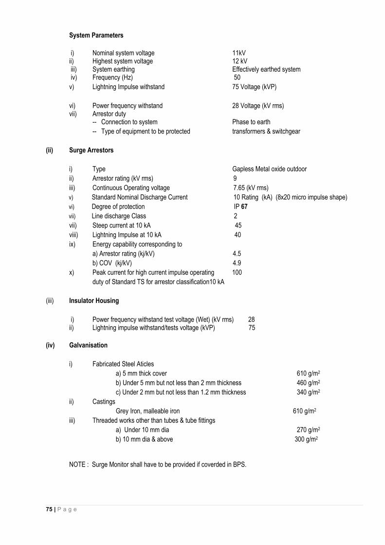
75 | P a g e
System Parameters
i) Nominal system voltage 11kV
ii) Highest system voltage 12 kV iii) System earthing Effectively earthed system iv) Frequency (Hz) 50
v) Lightning Impulse withstand 75 Voltage (kVP)
vi) Power frequency withstand 28 Voltage (kV rms) vii) Arrestor duty -- Connection to system Phase to earth
-- Type of equipment to be protected transformers & switchgear
(ii) Surge Arrestors
i) Type Gapless Metal oxide outdoor
ii) Arrestor rating (kV rms) 9
iii) Continuous Operating voltage 7.65 (kV rms)
v) Standard Nominal Discharge Current 10 Rating (kA) (8x20 micro impulse shape)
vi) Degree of protection IP 67
vii) Line discharge Class 2
vii) Steep current at 10 kA 45
viii) Lightning Impulse at 10 kA 40
ix) Energy capability corresponding to
a) Arrestor rating (kj/kV) 4.5
b) COV (kj/kV) 4.9
x) Peak current for high current impulse operating 100
duty of Standard TS for arrestor classification10 kA
(iii) Insulator Housing
i) Power frequency withstand test voltage (Wet) (kV rms) 28 ii) Lightning impulse withstand/tests voltage (kVP) 75
(iv) Galvanisation
i) Fabricated Steel Aticles
a) 5 mm thick cover 610 g/m2
b) Under 5 mm but not less than 2 mm thickness 460 g/m2
c) Under 2 mm but not less than 1.2 mm thickness 340 g/m2
ii) Castings
Grey Iron, malleable iron 610 g/m2
iii) Threaded works other than tubes & tube fittings
a) Under 10 mm dia 270 g/m2
b) 10 mm dia & above 300 g/m2
NOTE : Surge Monitor shall have to be provided if coverded in BPS.

76 | P a g e
(II) DISTRIBUTION CLASS SURGE ARRESTORS
Distribution class surge arrestors are generally used in distribution Transformer Substations only.
II. INTRODUCTION
This section covers the specification of Distribution class Surge Arrestor for 11kV transmission lines, transformers
etc.
III. STANDARDS
The design, manufacture and performance of Surge Arrestors shall comply with IS: 3070 Part-3 and other
specific requirements stipulated in the specification. Unless otherwise specified, the equipment, material and
processes shall conform to the latest applicable Indian/International Standards as listed hereunder :
IS:2071- 1993 (Part-1)
Methods of High Voltage Testing General Definitions & Test
IS:2071-1974 (part-2) Test Procedures
IS:2629-1985 Recommended Practice for hot dip galvanizing on Iron & Steel
IS:2633-1986 Method for Testing uniformity of coating of zinc coated Articles.
IS3070-1993 (Part–3) Specification for surge arrestor for alternating current systems. Metal-Oxide lightening
arrestors without gaps
IS:4759-1996 Specification for hot dip zinc coating on Structural Steel and Other allied products.
IS:5621-1980 Hollow Insulators for use in Electrical Equipment.
IS:6209-1982
Methods of Partial discharge measurement.
IS:6745
Method for determination of mass of zinc coating on zinc coated iron and steel articles
ANSI/IEEE-C.62.11 : Metal oxide, Surge Arrestor for AC Power (1982) Circuits.
IEC –60099-4 Surge Arrestors
(i) The equipment complying with any other internationally accepted standards shall also be considered if it
ensures performance equivalent to or superior to the Indian Standards.
IV. GENERAL REQUIREMENT
(i) The metal oxide gap less Surge Arrestor without any series or shunt gap shall be suitable for protection of 11 kV
side of Distribution Transformers, associated equipment and 11 kV lines from voltage surges resulting from
natural disturbance like lightning as well as system disturbances.
(ii) The surge arrestor shall draw negligible current at operating voltage and at the same time offer least
resistance during the flow of surge current.
(iii) The surge arrestor shall consist of non-linear metal oxide resistor elements placed in series and housed in
electrical grade porcelain housing / silicon polymericof specified Creepage distance.
(iv) The assembly shall be hermetically sealed with suitable rubber gaskets with effective sealing system
arrangement to prevent ingress of moisture.

77 | P a g e
(v) The surge arrestor shall be provided with line and earth terminals of suitable size. The ground side terminal of
surge arrestor shall be connected with 25x6 mm galvanized strip, one end connected to the surge
arrestor and second end to a separate ground electrode. The contractor shall also recommend the
procedure which shall be followed in providing the earthing/system to the Surge Arrestor.
(vi) The surge arrestor shall not operate under power frequency and temporary over voltage conditions but under
surge conditions, the surge arrestor shall change over to the conducting mode.
(vii) The surge arrestor shall be suitable for circuit breaker performing 0-0.3 min-CO-3 min-CO- duty in the system.
(viii) The reference current of the arrestor shall be high enough to eliminate the influence of grading and stray
capacitance on the measured reference voltage.
(ix) The Surge Arrestor shall be thermally stable and the contractor shall furnish a copy of thermal stability test with
the bid.
(x) The arrestor shall be capable of handling terminal energy for high surges, external pollution and transient over
voltage and have low losses at operating voltages.
V. ARRESTOR HOUSING
(i) The arrestor housing shall be made up of silicon polymeric housing and shall be homogenous, free from
laminations, cavities and other flaws of imperfections that might affect the mechanical and dielectric quality. The
housing shall be of uniform Grey (for silicon polymeric) colour, free from blisters, burrs and other similar
defects.
(ii) The housing shall be so coordinated that external flashover shall not occur due to application of any impulse or
switching surge voltage up to the maximum design value for arrestor. The arrestors shall not fail due to
contamination.
(iii) Sealed housings shall exhibit no measurable leakage.
VI. ARRESTOR MOUNTING
The arrestors shall be suitable for mounting on 4 pole/2 pole structure used for pole mounted transformer and for
incoming and outgoing lines.
VII. FITTINGS & ACCESSORIES
(i) The surge arrestor shall be complete with disconnector and terminal connectors and all other accessories.
(ii) The terminals shall be non-magnetic, corrosion proof, robust and of adequate size and shall be so located that
incoming and outgoing connections are made with minimum possible bends. The top metal cap and base of
surge arrestor shall be galvanized. The line terminal shall have a built in clamping device which can be adjusted
for both horizontal and vertical take off.
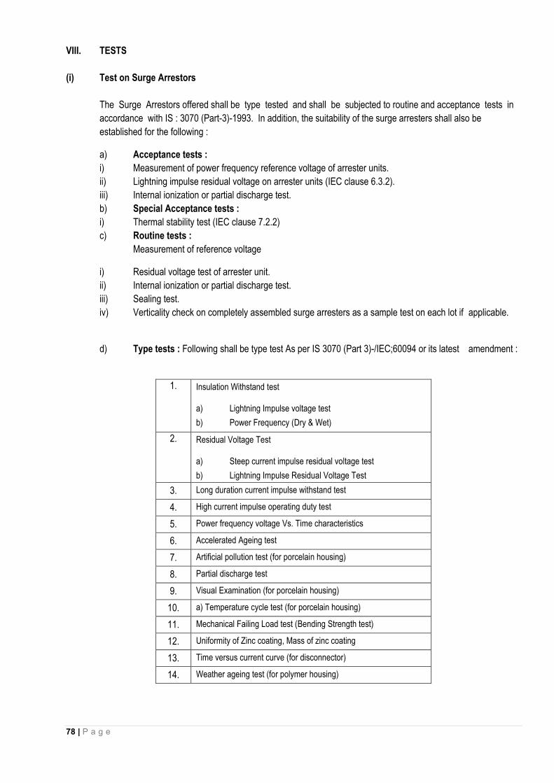
78 | P a g e
VIII. TESTS
(i) Test on Surge Arrestors
The Surge Arrestors offered shall be type tested and shall be subjected to routine and acceptance tests in
accordance with IS : 3070 (Part-3)-1993. In addition, the suitability of the surge arresters shall also be
established for the following :
a) Acceptance tests :
i) Measurement of power frequency reference voltage of arrester units.
ii) Lightning impulse residual voltage on arrester units (IEC clause 6.3.2).
iii) Internal ionization or partial discharge test.
b) Special Acceptance tests :
i) Thermal stability test (IEC clause 7.2.2)
c) Routine tests :
Measurement of reference voltage
i) Residual voltage test of arrester unit.
ii) Internal ionization or partial discharge test.
iii) Sealing test.
iv) Verticality check on completely assembled surge arresters as a sample test on each lot if applicable.
d) Type tests : Following shall be type test As per IS 3070 (Part 3)-/IEC;60094 or its latest amendment :
1. Insulation Withstand test
a) Lightning Impulse voltage test
b) Power Frequency (Dry & Wet)
2. Residual Voltage Test
a) Steep current impulse residual voltage test
b) Lightning Impulse Residual Voltage Test
3. Long duration current impulse withstand test
4. High current impulse operating duty test
5. Power frequency voltage Vs. Time characteristics
6. Accelerated Ageing test
7. Artificial pollution test (for porcelain housing)
8. Partial discharge test
9. Visual Examination (for porcelain housing)
10. a) Temperature cycle test (for porcelain housing)
11. Mechanical Failing Load test (Bending Strength test)
12. Uniformity of Zinc coating, Mass of zinc coating
13. Time versus current curve (for disconnector)
14. Weather ageing test (for polymer housing)

79 | P a g e
(ii) The maximum residual voltages corresponding to nominal discharge current of 5 kA for steep current,
impulse residual voltage test, lightning impulse protection level and switching impulse level shall generally
conform to Annex-K of IEC-99-4.
(iii) The contractor shall furnish the copies of the type tests and the characteristics curves between the residual
voltage and nominal discharge current of the offered surge arrestor and power frequency voltage v/s
time characteristic of the surge arrestor subsequent to impulse energy consumption as per clause 6.6.7 of
IS:3070 (Part-3) offered alongwith the GTP.
(iv) The surge arrestor housing shall also be type tested and shall be subjected to routine and acceptance tests in
accordance with IS: 5621
(v) GALVANIZATION TEST
All Ferrous parts exposed to atmospheric condition shall have passed the type tests and be subjected to
routine and acceptance tests in accordance with IS:2633 & IS 6745.
(vi) TEST ON SURGE ARRESTOR DISCONNECTORS
The test shall be performed on surge arrestors which are fitted with arrestor disconnector or on the disconnector
assembly alone if its design is such as to be un-affected by the heating of adjacent parts of the arrestor in its
normally installed portion in accordance with IS:3070 (Part-3).
IX. NAME PLATE
(i) The name plate attached to the arrestor shall carry the following information :
Rated Voltage Continuous Operation Voltage Normal discharge current Pressure relief rated current Manufacturers Trade Mark Name of Sub-station Year of Manufacturer Name of the manufacture Name of Client Purchase Order Number along with date
X. DRAWINGS AND INSTRUCTION MANUALS
The successful bidder shall furnish to the purchaser the following drawings and literature for approval :
(i) Outline dimensional drawings of Surge Arrestor and all accessories.
(ii) Assembly drawings and weights of main component parts.
(iii) Drawings of terminal clamps.
(iv) Arrangement of earthing lead.
(v) Minimum air clearance to be maintained of line components to ground.
(vi) Name plate
(vii) Instructions manual
(viii) Drawing showing details of pressure relief valve

80 | P a g e
(ix) Volt-time characteristics of surge arrestors
(x) Detailed dimensional drawing of porcelain housing/Silicon polymeric i.e. internal diameter, external
diameter, thickness, height, profile, creepage distance, dry arcing distance etc.
XI. TECHNICAL PARTICULARS
(i) The surge arrestors shall conform to the following standard technical requirements. The Insulation values shall
be enhanced considering the altitude of operation & other atmospheric conditions.
System Parameters
i) Nominal system voltage 11kV
ii) Highest system voltage 12 kV
iii) System earthing Solidly earthed system
iv) Frequency (Hz) 50 viii) Lightning Impulse withstand 75 Voltage (kVP) ix) Power frequency withstand 28 Voltage (kV rms) vii) Arrestor duty
-- Connection to system Phase to earth
-- Type of equipment to be protected 11 kV transformers & switchgear
(ii) Surge Arrestors
i) Type Gapless Metal oxide outdoor
ii) Arrestor rating (kV rms) 9
iii) Continuous Operating voltage (kV rms) 7.65
iv) Nominal Discharge Current 5 Rating (kA) (8x20 micro impulse shape)
v) Long Duration discharge class Distribution class
vi) Maximum residual voltage (kV peak)
a) at 5 kA 27
vii) Partial discharge at 1.05 COV not greater than 50 (PC)
viii) High current impulse withstand voltage at 5 kA (kVp) 65
XII. INSULATOR HOUSING
i) Power frequency withstand test voltage (Wet) (kV rms) 28
ii) Lightning impulse withstand/tests voltage (kVP) 75
iii) Creepage distance not less than (mm) 300
XIII. GALVANISATION
i) Fabricated Steel Articles
a) 5 mm thick cover 610 g/m2
b) Under 5 mm but not less than 2 mm thickness 460 g/m2
c) Under 2 mm but not less than 1.2 mm thickness 340 g/m2
ii) Castings
Grey Iron, malleable iron 610 g/m2

81 | P a g e
iii) Threaded works other than tubes & tube fittings
a) Under 10 mm dia 270 g/m2
b) 10 mm dia & above 300 g/m2
1. TECHNLCAL PARICULARS OF COMPOSIT POLYMERIC PIN INSULATOR FOR 11 KV
Sl. No Description Unit 11KV , 5 KN , PIN INSULATOR
1. Type of Insulator Composite polymeric Insulators 2. Standard according to which the Insulator manufacture
and tested IES-61109 with up to date
amendments 3. Name of material used in manufacture Of the insulator
with class/grade Silicon/ Polyolefin material
(a) Material of core (FRP rod) i) E-glass or ECR- glass ii) Boron content
ECR glass boron content free
(b) Material of housing &Weather sheds Silicon content by weight
36%
(c) ( material of end fitting ) Hot dip galvanized high strength steel
(d) Sealing compound for end fittings Silicon based sealants 4. Color Grey/ Red 5. Electrical characteristics (a) Normal system voltage KV(rms ) 11 KV (b) Highest system voltage KV(rms) 12 KV
(c) Dry power Frequency withstand voltage KV(rms ) 35 KV (d) Wet power frequency withstand voltage KV (rms
) 35 KV
(e) Dry flashover voltage KV(rms) >35KV (f) Wet flashover voltage KV(rms) >35KV (g) Dry lighting impulse withstand voltage
a) Positive b)Negative
KV(peak) KV(peak)
75KV 75 KV
(h) Dry lighting impulse flashover voltage c) positive d) Negative
KV(peak) KV(peak)
95KV 95 KV
(i) R/V at 1MHz when energized at 10KV/30KV(rms) under dry condition
Microvolt As per IEC specification
(j) Creepage distance (mm) mm 320 mm 6. Mechanical characteristics (a) Minimum failing load KN 5KN 7. Dimension of insulator As per type test (i) Weight Kg 1.0 Kg (Approx) (ii) Dia of FRP rod mm 16 mm (iii) Length of FRP rod mm drawing to be attached (iv) Die. Of Weather sheds mm drawing to be attached (v) Thickness of housing mm (3mm-Min) (vi) Dry arc distance mm drawing to be attached Dimension drawing of insulator including weight with Provided

82 | P a g e
clearances min weight enclosed 8. Method of fixing of sheds to housing (specify single
moulder Modular construction moulding ) Modular Design
9. No. of Weather sheds Drawing to be attached 10. Types of sheds Drawing to be attached (i) Aerodynamic Aerodynamic (ii) With under ribs ------------------------- 11. Packing details Each insulator in poly bag
then packed in master carton- 7Ply
(a) Types of packing Corrugated Bodies (b) No. of insulator each pack One master carton box
containing 16 Pcs (c) Gross weight of package 16 KG ( approx. ) 12. Any other particulars which the bidder may like to give ----------------------- 13 Performance Guarantee ( from date of commissioning) 18 month

83 | P a g e
SECTION -7
FORM FOR GUARANTEED TECHNICAL PARTICULARS
All the GTPs are to be duly signed with sealed with date by the bidders.

84 | P a g e
GUARANTEED TECHNICAL AND OTHER PARTICULARS FOR 11 kV PSC POLE[ 9.75M]
SL. NO.
DESCRIPTION UNIT Required Technical specs. Bidders offer
Name of the bidder
1 Name of Manufacturer
2 Address of manufacture
3 Country in origin
4 IS Standards Application IS 1343-1960
5 Type of Pole PSC
6 Total length Mtrs. 9.75
7 Depth of Plantation Mtrs. 1.8
A Bottom Depth mm 350
B Top depth Mm 175
C Breadth Mm 120
8 Dia of Pre Stressing wire Mm 4
9 No. of tension wire per pole 22 nos. of 4 mm dia
10
Min. ultimate tensile strength 4 mm HT Wire
Kg/sq mm
175
11
Min initial of 4 mm wire Kg/Wire 1865
12 Spacing HT Wires As per IS
13 Quantity of HT Wire Per Pole Kg 21.45
14 Link and Spiral Kg 3.54[ 4 nos. 5 mm in botton
and 4 nos. 5 mm in top]
15 MS Spiral 3 mm Dia of 150 c/c
16 Maximum Aggregate Size 12 mm
17 Total Weight per Pole Kg 750
18 Min. Clear Cover Mm 20
19 Factor of Safety 2.5
20 Concrete grade M - 20
21 Ultimate Load Kg 675
22 Earthing shall be provided by 4 mm dia. Galvanized iron wire embedded in concrete
Projecting from the pole at the length of 50 mm at 215 from
top and 150 mm below ground level
23 One mark to be provided at ground level
Mtr. 1.8
24 28 Days cube strength of the concrete [Min] as per IS 456-2000
Kg/sq. cm
420

85 | P a g e
GUARANTEED TECHNICAL AND OTHER PARTICULARS FOR 70 SQ. MM COVERED CONDUCTOR.
SN. Parameters Bidder’s offer
1 Conductor type
2 Lay up of Conductors (mm)
3 Conductor Dia (mm)
4 Inner Semiconducting Layer thickness (mm)
5 Inner XLPE Layer thickness (mm)
6 Outer UV Resistance - XLPE Thickness (mm)
7 Over all diameter (Min-Max) (mm)
8 Weight (Kg/Km)
9 Rated Operated Voltage (KV)
10 DC-resistance at 20 Degree C, Maximum (Ohm/KM)
11 Resistance Temperature coefficient (/0C)
12 Lightening Impulse withstand strength of XLPE Layer (KV)
13 Maximum Continuos Operating temperature (0C)
14 Max load(IEC 61597), cond.temp 80 °C, air temp. 40 °C, wind speed 0.5 m/s, Solar radiation 1045W/m², Approximate value (A)
15 Max short circuit current, 1 sec (KA)
16 Tensile Strength of Conductors (kN)
17 Aluminium Alloy Marking The Conductor Drum shall be marked with the following:
1) Manufacturer’s name, 2) APDCL “SOPD 2018-19” 3) Size and type of conductor, 4) Net weight of conductor in Kg, 5) Gross weight of conductor in Kg, 6) Length of conductor in meter, 7) BIS Standard Mark.
GUARANTED TECHNICAL PARTICULARS OF 11 KV COMPOSITE POLYMER PIN INSULATORS [5
kN]
S.N Description Bidder’s offer 1 Name of Manufacturer 2 Address:
(a) Registered Office (b) Factory
3 Type of Insulators 4 Standard specification to which the insulators manufactured and tested 5 Name of Material used in manufacture of the Insulator ( With class/ Grade)
(a) Material of core rod (b) Material of Housing & Weather sheds (silicon content by weight) (c) Material of end fittings : tongue/ clevis (d) Sealing compound for end fitting
6 Colour Glaze of Insulator 7 Electrical Characteristics:

86 | P a g e
(a) Nominal System Voltage ( kV RMS) (b) Highest System voltage (kV RMS) (c) Dry power frequency withstand (kV RMS) (d) Wet power frequency withstand (kV RMS) (e) Dry flash over voltage (kV RMS) (f) Wet flash over voltage (kV RMS) (g) Dry lightening impulse withstand voltage (a) Positive (kV Peak) (b) Negative (kV Peak) (h) Dry lightening impulse flashover voltage (a) Positive (kV Peak) (b) Negative (kV Peak) (i) RIV at 1MHz when energized at 10kV/30kV(rms) under dry condition(microvolt) (j) Creepage distance (min) mm
8 Mechanical Characteristics: Minimum failing load(KN)
9 dimensions of insulator: (i) Weight(kg) (ii) dia of FRP rod(mm) (iii) Length of ERP rod(MM) (iv) dia of weather sheds (mm) (v) Thickness of housing (mm) (vi) Dry arc distance(mm)
10 Dimensioned drawings of Insulator(including weight with tolerances in weight) enclosed
11 Method of fixing of sheds to housing specify):- Single mould or modular construction( injection moulding/ compression moulding)
12 No. of weather sheds 13 Type of sheds
(i) Aerodynamic (ii) With under ribs
14 Packing details (a) Type of packing (b) No. of Insulators in each pack (c) Gross weight of package
GAURANTEED TECHNLCAL PARTICULARS OF COMPOSIT POLYMERIC DISC INSULATOR FOR 11 KV, 45 KN Sl. No
Description Unit Bidder’s offer
Name of the manufacturer Address of the manufacturer Is the manufacture is ISO 9001-2000 certified
1. Type of Insulator 2. Standard according to which the Insulator manufacture and
tested
3. Name of material used in manufacture Of the insulator with class/grade
(a) Material of core (FRP rod) i) E-glass or ECR- glass ii) Boron content
(b) Material of housing &Weather sheds Silicon content by weight (c) ( material of end fitting ) (d) Sealing compound for end fittings 4. Color

87 | P a g e
5. Electrical characteristics (a) Normal system voltage KV(rms ) (b) Highest system voltage KV(rms) (c) Dry power Frequency withstand voltage KV(rms ) (d) Wet power frequency withstand voltage KV (rms ) (e) Dry flashover voltage KV(rms) (f) Wet flashover voltage KV(rms) (g) Dry lighting impulse withstand voltage
a) Positive b)Negative
KV(peak)
KV(peak)
(h) Dry lighting impulse flashover voltage c) positive d) Negative
KV(peak)
KV(peak)
(i) R/V at 1MHz when energized at 10KV/30KV(rms) under dry condition
Microvolt
(j) Creepage distance (mm) Mm 6. Mechanical characteristics (a) Minimum failing load KN 7. Dimension of insulator (i) Weight Kg (ii) Dia of FRP rod Mm (iii) Length of FRP rod Mm (iv) Die. Of Weather sheds Mm (v) Thickness of housing Mm (vi) Dry arc distance Mm
Dimension drawing of insulator including weight with clearances min weight enclosed
8. Method of fixing of sheds to housing (specify single moulder Modular construction moulding )
9. No. of Weather sheds 10. Types of sheds (i) Aerodynamic (ii) With under ribs 11. Packing details (a) Types of packing (b) No. of insulator each pack (c) Gross weight of package 12. Any other particulars which the bidder may like to give
GGUUAARRAANNTTEEEEDD TTEECCHHNNIICCAALL PPAARRTTIICCUULLAARRSS FFOORR HHAARRDDWWAARREE FFIITTTTIINNGG [[ 4455 KKNN,, CCLLEEAAVVAAGGEE AANNDD EEYYEE TTYYPPEE]]
SN Description unit Required TS Bidder's Offer
1 Name of the manufacturer
2 Address of manufacturer
3 Voltage Class kV 11
4 Is the manufacturer has ISO 9001- 2000 Yes/ No
5 Type
6 Applicable Standard IS 2486
7 Insulator Coupling Cleavage and
Eye
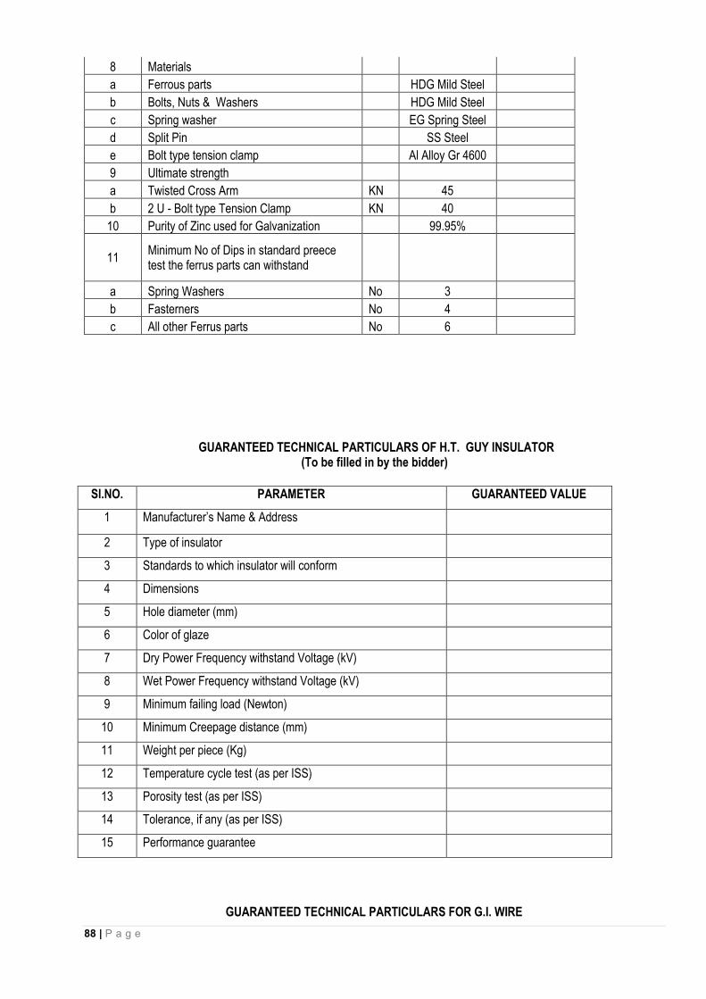
88 | P a g e
8 Materials
a Ferrous parts HDG Mild Steel
b Bolts, Nuts & Washers HDG Mild Steel
c Spring washer EG Spring Steel
d Split Pin SS Steel
e Bolt type tension clamp Al Alloy Gr 4600
9 Ultimate strength
a Twisted Cross Arm KN 45
b 2 U - Bolt type Tension Clamp KN 40
10 Purity of Zinc used for Galvanization 99.95%
11 Minimum No of Dips in standard preece test the ferrus parts can withstand
a Spring Washers No 3
b Fasterners No 4
c All other Ferrus parts No 6
GUARANTEED TECHNICAL PARTICULARS OF H.T. GUY INSULATOR
(To be filled in by the bidder)
GUARANTEED TECHNICAL PARTICULARS FOR G.I. WIRE
Sl.NO. PARAMETER GUARANTEED VALUE
1 Manufacturer’s Name & Address
2 Type of insulator
3 Standards to which insulator will conform
4 Dimensions
5 Hole diameter (mm)
6 Color of glaze
7 Dry Power Frequency withstand Voltage (kV)
8 Wet Power Frequency withstand Voltage (kV)
9 Minimum failing load (Newton)
10 Minimum Creepage distance (mm)
11 Weight per piece (Kg)
12 Temperature cycle test (as per ISS)
13 Porosity test (as per ISS)
14 Tolerance, if any (as per ISS)
15 Performance guarantee

89 | P a g e
(To be filled in by the bidder)
SN Description Required Technical Specification
Bidder’s Offer
Name of the Manufacturer
Address of the manufacturer
Is the manufacture has ISO 9001-2000 certification
A. G.I. Wire (4 mm dia)
1. Size of Wire
2. Tolerance in size of wire
3. Tensile strength
4. Wrapping list
5. Galvanising conforming to IS : 4826 – 1968
6. Guarantee
B. G.I. Wire (5 mm dia)
1. Size of Wire
2. Tolerance in size of wire
3. Tensile strength
4. Wrapping list
5. Galvanising conforming to IS : 4826 – 1968
6. Performance guarantee
GUARANTEED TECHNICAL PARTICULARS FOR C.I. PIPE (EARTH)
(To be filled in by the bidder)
Sl.No. Description Required Technical Specification
Bidder’s offer
1. Name of the manufacturer -
2. Address of the manufactruer -
3. Length of Pipe 1.8 Mtr
4. Diameter of Pipe 100 mm

90 | P a g e
5. External Dia of Pipe As per TS
6. Thickness of Pipe As per TS
7. Internal Dia of Socket As per TS
8. Thickness of Socket As per TS
7. Internal Depth of Socket As per TS
8. Internal Radius of Socket As per TS
9. Width of Grooves of Socket As per TS
10. External Dia of Grooves Socket As per TS
11. Weight of Pipe As per TS
12. Hydraulic Test As per TS
13. Guarantee As per TS
GUARANTEED TECHNICAL PARTICULARS FOR Insulation Piercing Connectors(IPC) (To be filled in by the bidder)
SN Description unit Required TS Bidder's Offer
1 Name of the manufacturer
2 Address of manufacturer
3 IS the manufacturer of the accessories certified as ISO 9001-2000 Company Yes/No
a Copies of certificate enclosed Yes/No
b Are GA Drawing enclosed IS 2486
4 Product designation IPC
5 Applicable Standard As per NFC 33 020-1998
6 Range of the cable size : Main & Tap
a Main 50-90 Sq. mm
b Tap 50-90 Sq. mm
7 Material Composition
a Body
Weather & UV Resistant Glass fibre Reinforce Polymer
b Contact Plates Tinned Copper

91 | P a g e
c Bolts
Galvanized Steel
d Seals & end
Elastomer
8
Is any metallic part carrying potential in operation exposed during installation
9 Are end caps of branch cable Yes/No
a Slide on Tap
Yes/No
b Rigid Yes/No
10 Are torque limiting shear heads provided to tightening bolts
Yes/No
11 Marking
a Make
b Main Range
c Tap Range
12 System Frequency in Hz Hz 50
13 Voltage withstand under water emersion in KV
Min 15 Kv for 1 min
14 Min & Max. Torque defined in Nm
(a) Min. Nm 19
(b) Max. Nm 25
15 Rated Tightening torque in Nm Nm 22
16 Dimensions As per Drawing C-AJA4030134
------------------------------ X -------------------------------