Asme Section II a Sa-350 Sa-350m
12
2007 SECTION II, PART A SA-350 / SA-350M SPECIFICATION FOR CARBON AND LOW-ALLOY STEEL FORGINGS, REQUIRING NOTCH TOUGHNESS TESTING FOR PIPING COMPONENTS SA-350/SA-350M (Identical with ASTM Specification A 350/A 350M-02b except for the deletion of 6.1.2 and 14.1, revision to 14.2.5, and test reports have been made mandatory.) 1. Scope 1.1 This specification covers s everal grades of ca rbon and low-alloy steel forged or ring-rolled flanges, forged fittings and valves intended primarily for low-temperature service and requiring notch toughness testing. They are made to specified dimensions, or to dimensional standards, such as the ASME and API Specifications referenced in Section 2. Although this specification covers some piping compon ent s mac hin ed from rolled bar and sea mle ss tubular materials (see 5.3.3), it does not cover raw material pro- duced in these product forms. 1.2 No limitation on size is intended b eyond the ability of the manufacturer to obtain the specified requirements. However, Class 3 of Grade LF787 is only available in the quenched-and-precipitation heat treated condition. 1.3 Supplementary requireme nts are provided for use when additi onal testin g or inspe ction is desir ed. These shall apply only when specified by the purchaser in the order. 1.4 This specification is expre ssed in both inch-pound units and in SI units. However, unless the order specifies the applicable “M” specification designation (SI units), the material shall be furnished to inch-pound units. 1.5 The value s stated in either inch-p ound units or SI units are to be regarded separately as standard. Within the text, the SI units are shown in brackets. The values stated in each system are not exact equivalents; therefore, each sys tem must be used ind epe nde ntl y of the other. Combining value s from the two syste ms may resu lt in n onco nfor mance with the specification. NOTE 1 — Refer to Test Methods and Definitions A 370 for notes on significance of notched-bar impact testing. 585 2. Re fer enc ed Doc ume nts 2.1 ASTM Standards: A 370 Test Methods and Definitions for Mechanical Test- ing of Steel Products A 788 Specification for Steel Forgings, General Require- ments A 961 Specification for Common Requirements for Steel Flanges, Forged Fittings, Valves, and Parts for Piping Applications 2.2 ASME Standards: B 16.5 Steel Pipe Flanges and Flanged Fittings B 16.9 Factory-Made Wrought Steel Butt-Welding Fittings B 16.10 Face-to-Face and End-to-End Dimensions of Fer- rous Valves B 16.11 Forged Steel Fittings, Socket-Welding and Threaded B 16.30 Unfired Pressure Vessel Flange Dimensions B 16.34 Valves-Flanged, Threaded, and Welding End B 16.47 Large Diameter Steel Flanges 2.3 ASME Boiler and Pressure Vessel Code: Section IX Welding Qualifications 2.4 AWS Standards: A 5.1 Mild Steel Covered Arc-Welding Electrodes A 5.5 Low-Alloy Steel Covered Arc-Welding Electrodes 2.5 API Standards: 600 Steel Gate Valves with Flanged or Butt-Welding Ends 602 Compact Design Carbon Steel Gate Valves for Refin- ery Use 605 Large Diameter Carbon Steel Flanges 3. Or der ing Inf ormati on 3.1 It is the purchaser’ s respons ibility to specify in the purchase order information necessary to purchase the Copyright ASME International Provided by IHS under license with ASME Licensee=Occ idental Chemical Corp New sub account/59104 19101 Not for Resale, 08/13/2007 15:16:12 MDT No reproduction or networking permitted without license from I HS
-
Upload
anonymous-ghpzn1x -
Category
Documents
-
view
274 -
download
0
Transcript of Asme Section II a Sa-350 Sa-350m

7/23/2019 Asme Section II a Sa-350 Sa-350m
http://slidepdf.com/reader/full/asme-section-ii-a-sa-350-sa-350m 1/12
2007 SECTION II, PART A SA-350 /SA-350M
SPECIFICATION FOR CARBON AND LOW-ALLOY
STEEL FORGINGS, REQUIRING NOTCH TOUGHNESS
TESTING FOR PIPING COMPONENTS
SA-350/SA-350M
(Identical with ASTM Specification A 350/A 350M-02b except for the deletion of 6.1.2 and 14.1, revision to 14.2.5, and test reports have beenmade mandatory.)
1. Scope
1.1 This specification covers several grades of carbon
and low-alloy steel forged or ring-rolled flanges, forged
fittings and valves intended primarily for low-temperature
service and requiring notch toughness testing. They are
made to specified dimensions, or to dimensional standards,
such as the ASME and API Specifications referenced in
Section 2. Although this specification covers some piping
components machined from rolled bar and seamless tubular
materials (see 5.3.3), it does not cover raw material pro-
duced in these product forms.
1.2 No limitation on size is intended beyond the abilityof the manufacturer to obtain the specified requirements.
However, Class 3 of Grade LF787 is only available in the
quenched-and-precipitation heat treated condition.
1.3 Supplementary requirements are provided for use
when additional testing or inspection is desired. These shall
apply only when specified by the purchaser in the order.
1.4 This specification is expressed in both inch-pound
units and in SI units. However, unless the order specifies
the applicable “M” specification designation (SI units), the
material shall be furnished to inch-pound units.
1.5 The values stated in either inch-pound units or SI
units are to be regarded separately as standard. Within the
text, the SI units are shown in brackets. The values stated
in each system are not exact equivalents; therefore, each
system must be used independently of the other. Combining
values from the two systems may result in nonconformance
with the specification.
NOTE 1 — Refer to Test Methods and Definitions A 370 for notes on
significance of notched-bar impact testing.
585
2. Referenced Documents
2.1 ASTM Standards:
A 370 Test Methods and Definitions for Mechanical Test-
ing of Steel Products
A 788 Specification for Steel Forgings, General Require-
ments
A 961 Specification for Common Requirements for Steel
Flanges, Forged Fittings, Valves, and Parts for Piping
Applications
2.2 ASME Standards:
B 16.5 Steel Pipe Flanges and Flanged Fittings
B 16.9 Factory-Made Wrought Steel Butt-Welding Fittings
B 16.10 Face-to-Face and End-to-End Dimensions of Fer-
rous Valves
B 16.11 Forged Steel Fittings, Socket-Welding and
Threaded
B 16.30 Unfired Pressure Vessel Flange Dimensions
B 16.34 Valves-Flanged, Threaded, and Welding End
B 16.47 Large Diameter Steel Flanges
2.3 ASME Boiler and Pressure Vessel Code:
Section IX Welding Qualifications
2.4 AWS Standards:
A 5.1 Mild Steel Covered Arc-Welding Electrodes
A 5.5 Low-Alloy Steel Covered Arc-Welding Electrodes
2.5 API Standards:
600 Steel Gate Valves with Flanged or Butt-Welding Ends
602 Compact Design Carbon Steel Gate Valves for Refin-
ery Use
605 Large Diameter Carbon Steel Flanges
3. Ordering Information
3.1 It is the purchaser’s responsibility to specify in
the purchase order information necessary to purchase the
yright ASME Internationalded by IHS under license with ASME Licensee=Occidental Chemical Corp New sub account/5910419101
Not for Resale, 08/13/2007 15:16:12 MDTeproduction or networking permitted without license from I HS
7/23/2019 Asme Section II a Sa-350 Sa-350m
http://slidepdf.com/reader/full/asme-section-ii-a-sa-350-sa-350m 2/12
SA-350 /SA-350M 2007 SECTION II, PART A
needed material. In addition to the ordering information
guidelines in Specification A 961, orders should include
the following information:
3.1.1 Additional requirements (see Table 1 foot-
notes).
4. General Requirements
4.1 Product furnished to this specification shall conform
to the requirements of Specification A 961, including any
supplementary requirements that are indicated in the pur-
chase order. Failure to comply with the general require-
ments of Specification A 961 constitutes nonconformance
with this specification. In case of conflict between the
requirements of this specification and Specification A 961,
this specification shall prevail.
5. Manufacture
5.1 Melting Process — The steel shall be produced by
any of the following primary processes: open-hearth, basic
oxygen, electric-furnace, or vacuum-induction melting
(VIM). The primary melting may incorporate separate
degassing or refining, and may be followed by secondary
melting using electroslag remelting (ESR), or vacuum-arc
remelting (VAR).
5.1.1 The steel shall be fully killed, fine-grain
practice.
5.1.2 The molten steel may be vacuum treated prior
to or during pouring of the ingot.
5.2 Discard — A sufficient discard shall be made to
secure freedom from injurious piping and undue segre-
gation.
5.3 Forging Process:
5.3.1 Material for forgings shall consist of ingots, or
forged, rolled, or strandcast blooms, billets, slabs, or bars.
5.3.2 The finished product shall be a forging as
defined in the Terminology section of Specification A 788.
5.3.3 Except for flanges of all types, hollow, cylindri-
cally-shaped parts may be machined from rolled bar or
seamless tubular materials provided that the axial lengthof the part is approximately parallel to the metal flow lines
of the stock. Other parts, excluding flanges of all types,
may be machined from hot-rolled or forged bar up through
and including NPS 4. Elbows, return bends, tees, and
header tees shall not be machined directly from bar stock.
5.4 Heat Treatment:
5.4.1 After hot working and before reheating for heat
treatment, the forging shall be allowed to cool substantially
below the transformation range.
586
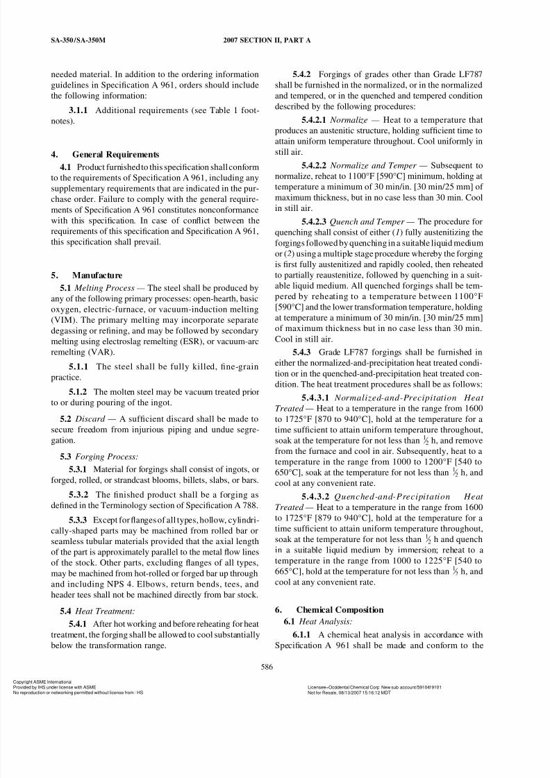
5.4.2 Forgings of grades other than Grade LF787
shall be furnished in the normalized, or in the normalized
and tempered, or in the quenched and tempered condition
described by the following procedures:
5.4.2.1 Normalize — Heat to a temperature that
produces an austenitic structure, holding sufficient time to
attain uniform temperature throughout. Cool uniformly in
still air.
5.4.2.2 Normalize and Temper — Subsequent to
normalize, reheat to 1100°F [590°C] minimum, holding at
temperature a minimum of 30 min/in. [30 min/25 mm] of
maximum thickness, but in no case less than 30 min. Cool
in still air.
5.4.2.3 Quench and Temper — The procedure for
quenching shall consist of either (1) fully austenitizing the
forgings followed by quenching in a suitable liquid medium
or (2) using a multiple stage procedure whereby the forging
is first fully austenitized and rapidly cooled, then reheated
to partially reaustenitize, followed by quenching in a suit-able liquid medium. All quenched forgings shall be tem-
pered by reheating to a temperature between 1100°F
[590°C] and the lower transformation temperature, holding
at temperature a minimum of 30 min/in. [30 min/25 mm]
of maximum thickness but in no case less than 30 min.
Cool in still air.
5.4.3 Grade LF787 forgings shall be furnished in
either the normalized-and-precipitation heat treated condi-
tion or in the quenched-and-precipitation heat treated con-
dition. The heat treatment procedures shall be as follows:
5.4.3.1 Normalized-and-Precipitation Heat
Treated — Heat to a temperature in the range from 1600to 1725°F [870 to 940°C], hold at the temperature for a
time sufficient to attain uniform temperature throughout,
soak at the temperature for not less than 1 ⁄ 2 h, and remove
from the furnace and cool in air. Subsequently, heat to a
temperature in the range from 1000 to 1200°F [540 to
650°C], soak at the temperature for not less than 1 ⁄ 2 h, and
cool at any convenient rate.
5.4.3.2 Quenched-and-Precipitation Heat
Treated — Heat to a temperature in the range from 1600
to 1725°F [879 to 940°C], hold at the temperature for a
time sufficient to attain uniform temperature throughout,
soak at the temperature for not less than 1 ⁄ 2 h and quench
in a suitable liquid medium by immersion; reheat to a
temperature in the range from 1000 to 1225°F [540 to
665°C], hold at the temperature for not less than 1 ⁄ 2 h, and
cool at any convenient rate.
6. Chemical Composition
6.1 Heat Analysis:
6.1.1 A chemical heat analysis in accordance with
Specification A 961 shall be made and conform to the
yright ASME Internationalded by IHS under license with ASME Licensee=Occidental Chemical Corp New sub account/5910419101
Not for Resale, 08/13/2007 15:16:12 MDTeproduction or networking permitted without license from I HS
7/23/2019 Asme Section II a Sa-350 Sa-350m
http://slidepdf.com/reader/full/asme-section-ii-a-sa-350-sa-350m 3/12
2007 SECTION II, PART A SA-350 /SA-350M
requirements as to chemical composition prescribed in
Table 1. Leaded steels shall not be permitted.
6.1.2 DELETED
6.2 Product Analysis:
6.2.1 The purchaser may make a product analysis
on products supplied to this specification in accordancewith Specification A 961.
7. Mechanical Properties
7.1 Tension Tests:
7.1.1 Requirements — The material shall conform to
requirements for tensile properties in Table 2.
7.1.1.1 The test specimen shall be obtained from
a rough or finished forging, or prolongation thereof. For
forgings under 10 000 lbs, at time of heat treatment, it
may be obtained from separately forged test blanks from
the same heat of steel as the production forgings. The testblank shall be reduced by forging in a manner similar to
that for the products represented, and shall receive approxi-
mately the same hot working and reduction and the same
heat treatment as the finished products represented. The
test material shall be treated in the same furnace at the
same time as the forging it represents, subject to the require-
ments of 7.1.2.1.
7.1.1.2 The test specimen shall represent all forg-
ings from the same heat and heat-treatment load whose
maximum thicknesses do not exceed the thickness of the
test forging or blank by more than 1 ⁄ 4 in. [6 mm].
7.1.2 Number of Tests — One tension test at roomtemperature shall be made in accordance with 7.1.1.2 from
each heat in each heat-treatment load.
7.1.2.1 If heat treatment is performed in either a
continuous or a batch-type furnace controlled within ±25°F
[±14°C] of the required heat-treatment temperature and
equipped with recording pyrometers so that complete rec-
ords of heat treatment are available and if the same heat-
treating cycles are used on the forgings represented by the
tension test, then one tension test from each heat shall be
required, instead of one tension test from each heat in each
heat treatment load in accordance with 7.1.1.2.
7.1.3 Test Locations and Orientations — The testspecimen shall be removed from the heaviest section of
the forging or test blank, at locations described in 7.1.3.1,
7.1.3.2, 7.1.3.5 or as close to these locations as practical,
subject to forging size and geometry.
7.1.3.1 For forgings or test blanks having a maxi-
mum heat-treated thickness, T , of 2 in. [50 mm] or less,
the longitudinal axis of the test specimen shall be taken at
mid-thickness and its mid-length shall be at least 2 in. [50
mm] from a second heat treated surface, exclusive of the
587
T dimension surfaces. (This is normally referred to as 1 ⁄ 2 T
by 2 in. [50 mm]).
7.1.3.2 For forgings or test blanks having a maxi-
mum heat-treated thickness, T , greater than 2 in. [50 mm],
the central axis of the test specimen shall be taken at least1 ⁄
4 T from the nearest heat-treated surface and at least T or
4 in. [100 mm], whichever is less, from any second heat-
treated surface. For quenched and tempered forgings, the
midlength of the test specimen shall be at least T from any
second heat-treated surface. See Fig. 1 for test specimen
location in separately forged test blanks for quenched and
tempered forgings.
7.1.3.3 Metal Buffers — The required distances
from heat treated surfaces may be obtained with metal
buffers instead of integral expansions. Buffer material may
be carbon or low alloy steel, and shall be joined to the
forging with a partial penetration weld that seals the buf-
fered surface. Specimens shall be located at 1 ⁄ 2 in. [13 mm]
minimum from the buffered surface of the forging. Buffersshall be removed and the welded areas subjected to mag-
netic particle test to assure freedom from cracks unless
the welded areas are completely removed by subsequent
machining.
7.1.3.4 The test specimen shall have its longitudi-
nal axis located parallel to the direction of major working
of the forging or test blank.
7.1.3.5 With prior purchaser approval, tests may
be taken at a depth (t ) corresponding to the distance from
the area of significant loading to the nearest heat treated
surface and at least twice this distance (2t ) from any second
surface. However, the test depth shall not be nearer to onetreated surface than 3 ⁄ 4 in. [19 mm] and to the second treated
surface than 11 ⁄ 2 in. [38 mm]. This method of test location
would normally apply to contour-forged parts, or parts
with thick cross-sectional areas where 1 ⁄ 4 T T testing
(7.1.3.2) is not practical. Sketches showing the exact test
locations shall be approved by the purchaser when this
method is used.
7.1.4 Test Method — Testing shall be performed in
accordance with Test Methods and Definitions A 370. The
test specimen shall be as large as is practicable and shall
be machined to the form and dimensions of Fig. 5 of Test
Methods and Definitions A 370. When seamless tubularmaterials are used, testing shall be performed on longitudi-
nal specimens in accordance with Annex A2, Steel Tubular
Products, of Test Methods and Definitions A 370.
7.2 Impact Test:
7.2.1 Requirements — The material shall conform to
the requirements for impact properties in Table 3 when
tested at the applicable standard temperature in Table 4
within the limits of 7.2.4.2 and 7.2.4.3. When subsize
specimens are used, the impact energy values obtained
yright ASME Internationalded by IHS under license with ASME Licensee=Occidental Chemical Corp New sub account/5910419101
Not for Resale, 08/13/2007 15:16:12 MDTeproduction or networking permitted without license from I HS
--``,`,,```,``,,`,`,``,`,```,,,-`-`,,`,,`,`,,`---
7/23/2019 Asme Section II a Sa-350 Sa-350m
http://slidepdf.com/reader/full/asme-section-ii-a-sa-350-sa-350m 4/12
SA-350 /SA-350M 2007 SECTION II, PART A
shall conform to Table 5 at energy values proportional to
standard size. Exceptions to this requirement are permissi-
ble when Supplementary Requirement S1 is specified by
the purchaser. Impact tests may be made at temperatures
different from those in Table 4, provided that the test
temperature is at least as low as the intended service tem-
perature, and that the forging is suitably marked to identifythe reported test temperature.
7.2.1.1 The test specimens shall be machined from
material obtained as in 7.1.
7.2.2 Number of Tests — Three specimens shall con-
stitute one test set. There shall be the same number of test
sets as tension tests in 7.1.2.
7.2.3 Test Locations and Orientations — The test
specimen shall be located and oriented as described in
7.1.3. The area under the notch of the impact test specimen
shall be used to locate the specimen with respect to the
second heat-treated surface. The base of the notch shall be
perpendicular to the nearest heat-treated surface.
7.2.4 Test Method — The notched bar impact test
shall be made in accordance with the procedure for the
Charpy V-notch type test as described in Test Methods
and Definitions A 370.
7.2.4.1 Standard size specimens shown in Fig. 11
of Test Methods and Definitions A 370 shall be used for
the impact test. Where the material is of insufficient thick-
ness, or the shape of the forging precludes standard size,
the largest obtainable subsize specimen described in Test
Methods and Definitions A 370 shall be used.
7.2.4.2 Where subsize specimens are used andrepresent forged material with thicknesses equal to or
greater than 0.394 in. [10 mm], and where the largest
obtainable specimen has a width along the notch of at least
8 mm, such specimen shall be tested at the temperature in
Table 4. Where the largest obtainable specimen has a width
along the notch less than 8 mm, the temperature for testing
shall be lower than the temperature in Table 4 by the
amount shown in Table 6 for the actual specimen width
tested.
7.2.4.3 Where subsize specimens are used and
represent forged material with thicknesses less than 0.394
in. [10 mm], and where the largest obtainable specimen
has a width along the notch of at least 80% of the forging
thickness, the specimen shall be tested at the temperature
in Table 4. Where the largest obtainable specimen has a
width along the notch of less than 80% of the material
thickness, the temperature for testing shall be lower than
the temperature in Table 4 by an amount equal to the
difference (referring to Table 6) between the temperature
reduction corresponding to the thickness of the material
represented, and the temperature reduction corresponding
to the specimen width actually tested.
588
7.3 Hardness Test:
7.3.1 Except when only one forging is produced, a
minimum of two forgings shall be hardness tested per
batch or continuous run as defined in 7.1.2.1 to ensure that
hardness of the forgings does not exceed 197 HB after
heat treatment for mechanical properties. The hardness
measurements shall be made in accordance with Test Meth-
ods and Definitions A 370. When only one forging is
produced, it shall be hardness tested to ensure that it meets
the 197 HB maximum of this specification. The purchaser
may verify that this requirement has been met by testing
at any location on the forging, provided that such testing
does not render the forging useless.
8. Hydrostatic Test
8.1 Forgings manufactured under this specification
shall be capable of passing a hydrostatic test compatible
with the rating of the finished item. Such tests shall beconducted by the manufacturer only when Supplementary
Requirement S57 of Specification A 961 is specified.
9. Workmanship, Finish, and Appearance
9.1 Forgings shall conform to the requirements of Spec-
ification A 961.
10. Retests
10.1 If any test specimen shows flaws or defective
machining, it may be discarded and another specimen sub-
stituted.
11. Rework and Retreatment
11.1 If the results of the mechanical tests do not con-
form to the requirements specified, the manufacturer may
reheat treat the forgings represented, and shall retest to the
applicable requirements.
11.2 Individually tested forgings meeting all require-
ments shall be acceptable.
11.3 Repair by Welding — Weld repairs shall be permit-
ted (see Supplementary Requirement S58 of SpecificationA 961) at the discretion of the manufacturer with the fol-
lowing limitations and requirements:
11.3.1 Repair by welding shall be made using weld-
ing procedures and welders qualified in accordance with
ASME Section IX of the Code. The weld procedure quali-
fication test shall also include impact tests of the weld
metal and heat-affected zone. All impact test specimens
shall have the longitudinal axis transverse to the weld and
the base of the notch normal to the weld surface. Weld
yright ASME Internationalded by IHS under license with ASME Licensee=Occidental Chemical Corp New sub account/5910419101
Not for Resale, 08/13/2007 15:16:12 MDTeproduction or networking permitted without license from I HS
--` ` ,` , ,` ` ` ,` ` , ,` ,` ,` ` ,` ,` ` ` , , ,-` -` , ,` , ,` ,` , ,` ---
7/23/2019 Asme Section II a Sa-350 Sa-350m
http://slidepdf.com/reader/full/asme-section-ii-a-sa-350-sa-350m 5/12
2007 SECTION II, PART A SA-350 /SA-350M
specimens shall have the notch in weld metal and heat-
affected zone specimens shall have the notch in the heat-
affected zone. The specimens shall be as large as permitted
by the weldment thickness. Where full-size specimens can
be obtained and where there is sufficient weldment thick-
ness, the weld specimen shall be taken with one side of
the specimen within 1 ⁄ 16 in. [1.6 mm] of the weld surface.Heat-affected zone impact test specimens shall be taken
at the same depth and locations applicable to the forging
in 7.1.3.1 and 7.1.3.2. When forgings are thermally treated
after repair welding, the weld procedure test plate shall be
subjected to the same thermal treatment. The mechanical
properties of the weld procedure qualification test shall
conform to Section 7.
11.3.2 Defects shall be completely removed by chip-
ping or grinding to sound metal as verified by magnetic
particle, or liquid penetrant inspection prior to welding.
11.3.3 For Grade LF1 forgings, and LF2 forgings
that are to be only stress-relieved after repair welding, theweld metal shall be deposited using carbon steel electrodes
E 7015, E 7016, or E 7018, complying with AWS A 5.1.
For Grade LF2 forgings in all other conditions of post-
weld heat treatment, the weld metal shall be deposited
using low-alloy steel electrodes E 7015-A1; E 7016-A1,
or E 7018-A1 complying with AWS 5.5; for Grade LF3
forgings the weld metal shall be deposited using low-alloy
steel electrodes E 8016-C2 or E 8018-C2 complying with
AWS A 5.5; for Grades LF5, LF9, and LF787 forgings,
the weld metal shall be deposited using low-alloy steel
electrodes E 8016-C1 or E 8018-C1 complying with AWS
A 5.5. For Grade LF6, the electrodes shall be low-hydro-
gen, E-XX15, E-XX16, or E-XX18 complying with AWSA 5.1 or A 5.5, as applicable.
11.3.4 After repair welding, the area welded shall
be completely free of defects as verified by magnetic parti-
cle or liquid penetrant inspection.
11.3.5 Forgings repair welded in the normalized,
normalized and tempered, or the quenched and tempered
conditions shall be stress-relieved after repair welding at
1100°F [590°C] minimum, but not higher than the tempera-
ture previously used for tempering the base metal of the
same forging, or shall be reheat treated in accordance
with 5.4.
11.3.6 When the purchaser specifies SupplementaryRequirement S5, the same requirements shall apply to the
weld procedure qualification tests.
11.3.7 Repair by welding shall not exceed 10% of the
surface area of the forging or 331 ⁄ 3% of the wall thickness of
the finished forging, or 3 ⁄ 8 in. [9.5 mm], whichever is less,
without prior approval of the purchaser.
11.3.8 When approval of the purchaser is obtained,
the limitations set forth in 11.3.7 may be exceeded, but all
other requirements of 11.3 shall apply.
589
12. Inspection
12.1 Inspection provisions of Specification A 961 shall
apply.
13. Rejection and Rehearing
13.1 Purchaser shall comply with provisions of Speci-
fication A 961.
14. Certification
14.1 DELETED
14.2 Test reports are required, they shall include certi-
fication that all requirements of this specification have been
met, and shall be traceable to the forging represented.
The specification designation included on test reports shall
include year of issue and revision letter, if any. The manu-
facturer shall provide the following where applicable:
14.2.1 Type heat treatment, Section 5,
14.2.2 Chemical analysis results, Section 6 (Table 1),
14.2.3 Product analysis results, 6.2 (Table 1),
14.2.4 Tensile property results, Section 7 (Table 2)
report the yield strength and ultimate strength, in ksi [MPa],
elongation and reduction in area, in percent,
14.2.5 Impact test results, 7.2 (Table 3, Table 4,
Table 5, and Table 6), including specimen size if subsize
samples were used,
14.2.6 Hardness results, 7.3.1,
14.2.7 Any supplementary testing required by the
purchase order, and
14.2.8 If repaired by welding, letter W is to follow
the ASTM designation.
15. Product Marking
15.1 In addition to the marking requirements of Speci-
fication A 961, manufacturer’s name (see Note 2) or symbol
shall be permanently marked on each forging.
NOTE 2 — For purposes of identification marking, the manufacturer
is considered the organization that certifies the piping component was
manufactured, sampled, and tested in accordance with this specification
and the results have been determined to meet the requirements of this
specification.
15.1.1 If the forgings have been quenched and tem-
pered or quenched-and-precipitation heat treated, the letters
QT shall be stamped on the forgings following the ASTM
designation.
15.1.2 Forgings repaired by welding shall be marked
with the letter W following the ASTM designation.
15.2 If identificationstamps areobjectionable anddetri-
mental to the forging, and when so stated on the purchase
yright ASME Internationalded by IHS under license with ASME Licensee=Occidental Chemical Corp New sub account/5910419101
Not for Resale, 08/13/2007 15:16:12 MDTeproduction or networking permitted without license from I HS
7/23/2019 Asme Section II a Sa-350 Sa-350m
http://slidepdf.com/reader/full/asme-section-ii-a-sa-350-sa-350m 6/12
SA-350 /SA-350M 2007 SECTION II, PART A
order, the marks may be painted or stenciled on the forging,
or stamped on a metal or plastic tag which shall be securely
attached to the forging.
15.3 When test reports are required, additional marks
shall be used as necessary to identify the part with the test
report.15.4 If the test temperature is other than the standard
temperature specified in Table 4, the mark shall also include
the suffix letter S to the grade and class and the test tempera-
ture. A prefix 0 to the test temperature shall indicate a less
than 0°F [-18°C] value. For example, LF2S 0175 denotes
a test temperature of –175°F [-115°C] for an LF2 part.
15.5 Parts meeting all requirements for more than one
class may be marked with more than one class such as
LF2 CL1/CL2; LF5 CL1/CL2, and so forth.
590
15.6 Bar Coding — In addition to the requirements in
15.1, 15.2, 15.3, 15.4, and 15.5, bar coding is acceptable
as a supplemental identification method. The purchaser
may specify in the order a specific bar coding system to
be used. The bar coding system, if applied at the discretion
of the supplier, should be consistent with one of the pub-
lished industry standards for bar coding. If used on smallparts, the bar code may be applied to the box or a substan-
tially applied tag.
16. Keywords
16.1 carbonequivalent; pipe fittings, steel; piping appli-
cations; pressure containing parts; steel flanges; steel forg-
ings, alloy; steel forgings, carbon; steel valves; temperature
service applications, low
yright ASME Internationalded by IHS under license with ASME Licensee=Occidental Chemical Corp New sub account/5910419101
Not for Resale, 08/13/2007 15:16:12 MDTeproduction or networking permitted without license from I HS
--` ` ,` , ,` ` ` ,` ` , ,` ,` ,` ` ,` ,` ` ` , , ,-` -` , ,` , ,` ,` , ,` ---
7/23/2019 Asme Section II a Sa-350 Sa-350m
http://slidepdf.com/reader/full/asme-section-ii-a-sa-350-sa-350m 7/12
2007 SECTION II, PART A SA-350 /SA-350M
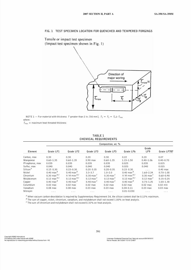
FIG. 1 TEST SPECIMEN LOCATION FOR QUENCHED AND TEMPERED FORGINGS
NOTE 1 — For material with thickness T greater than 2 in. [50 mm], T 2p T 3p T 4 ≥ T max
where:
T maxp maximum heat threated thickness
TABLE 1
CHEMICAL REQUIREMENTS
Composition, wt. %
Grade
Element Grade LF1 Grade LF2 Grade LF3 Grade LF5 Grade LF6 LF9 Grade LF787
Carbon, max 0.30 0.30 0.20 0.30 0.22 0.20 0.07
Manganese 0.60–1.35 0.60–1.35 0.90 max 0.60–1.35 1.15–1.50 0.40–1.06 0.40–0.70
Phosphorus, max 0.035 0.035 0.035 0.035 0.025 0.035 0.025
Sulfur, max 0.040 0.040 0.040 0.040 0.025 0.040 0.025
SiliconA 0.15–0.30 0.15–0.30 0.20–0.35 0.20–0.35 0.15–0.30 . . . 0.40 max
Nickel 0.40 maxB 0.40 maxB 3.3–3.7 1.0–2.0 0.40 maxB 1.60–2.24 0.70–1.00
Chromium 0.30 maxB,C 0.30 maxB,C 0.30 maxC 0.30 maxC 0.30 maxB,C 0.30 maxC 0.60–0.90
Molybdenum 0.12 maxB,C 0.12 maxB,C 0.12 maxC 0.12 maxC 0.12 maxB,C 0.12 maxC 0.15–0.25
Copper 0.40 maxB 0.40 maxB 0.40 maxC 0.40 maxC 0.40 maxB 0.75–1.25 1.00–1.30
Columbium 0.02 max 0.02 max 0.02 max 0.02 max 0.02 max 0.02 max 0.02 min
Vanadium 0.08 max 0.08 max 0.03 max 0.03 max 0.04–0.11 0.03 max 0.03 max
Nitrogen . . . . . . . . . . . . 0.01–0.030 . . . . . .
A When vacuum carbon-deoxidation is required by Supplementary Requirement S4, the silicon content shall be 0.12% maximum.B The sum of copper, nickel, chromium, vanadium, and molybdenum shall not exceed 1.00% on heat analysis.C The sum of chromium and molybdenum shall not exceed 0.32% on heat analysis.
591
yright ASME Internationalded by IHS under license with ASME Licensee=Occidental Chemical Corp New sub account/5910419101
Not for Resale, 08/13/2007 15:16:12 MDTeproduction or networking permitted without license from I HS

7/23/2019 Asme Section II a Sa-350 Sa-350m
http://slidepdf.com/reader/full/asme-section-ii-a-sa-350-sa-350m 8/12
SA-350 /SA-350M 2007 SECTION II, PART A
TABLE 2
TENSILE PROPERTIES AT ROOM TEMPERATUREA
Grades
LF6 LF787LF1 and LF2 LF3 Classes
LF5 Classes 1 and 2 LF5 Classes
Class 1 1 and 2 Class 2 Class 1 2 and 3 LF9 Class 2 Class 3
Tensile strength, ksi [MPa] 60–85 70–95 70–95 66–91 75–100 63–88 65–85 75–95
[415–585] [485–655] [485–655] [455–630] [515–690] [435–605] [450–585] [515–655]
Yield strength, min, ksi [MPa]B,C 30 [205] 36 [250] 37.5 [260] 52 [360] 60 [415] 46 [315] 55 [380] 65 [450]
Elongation:
Standard round specimen, or small 25 22 22 22 20 25 20 20
proportional specimen, min % in
4D gage length
Stripspecimenfor wallthickness5 ⁄ 16 28 30 30 30 28 28 28 28
in. (7.94 mm) and over and for
all small sizes tested in full sec-
tion; min % in 2 in. (50 mm)
Equation for calculating min elon- 48t + 13 48t + 15 48t + 15 48t + 15 48t + 13 48t + 13 48t + 13 48t + 13
gation for strip specimens thinner
than 5 ⁄ 16 in. (7.94 mm); min %
in 2 in. (50 mm)
t p actual thickness in inches
Reduction of area, min, % 38 30 35 40 40 38 45 45
A See 7.3 for hardness tests.B Determined by either the 0.2% offset method or the 0.5% extension under load method.C For round specimens only.
TABLE 3CHARPY V-NOTCH ENERGY REQUIREMENTS FOR STANDARD
SIZE [10 by 10 mm] SPECIMENS
Minimum Impact
Energy Required for Minimum Impact
Average of Each Set Energy Permitted for
of Three Specimens, One Specimen only of
Grade ft-lbf [J] a Set, ft-lbf [J]
LF1 and LF9 13 [18] 10 [14]
LF2, Class 1 15 [20] 12 [16]
LF3, Class 1 15 [20] 12 [16]
LF5, Class 1 and 2 15 [20] 12 [16]
LF787, Classes 2 and 3 15 [20] 12 [16]
LF6, Class 1 15 [20] 12 [16]
LF2, Class 2 20 [27] 15 [20]
LF3, Class 2 20 [27] 15 [20]
LF6, Classes 2 and 3 20 [27] 15 [20]
592
yright ASME Internationalded by IHS under license with ASME Licensee=Occidental Chemical Corp New sub account/5910419101
Not for Resale, 08/13/2007 15:16:12 MDTeproduction or networking permitted without license from I HS
--` ` ,` , ,` ` ` ,` ` , ,` ,` ,` ` ,` ,` ` ` , , ,-` -` , ,` , ,` ,` , ,` ---
7/23/2019 Asme Section II a Sa-350 Sa-350m
http://slidepdf.com/reader/full/asme-section-ii-a-sa-350-sa-350m 9/12
2007 SECTION II, PART A SA-350 /SA-350M
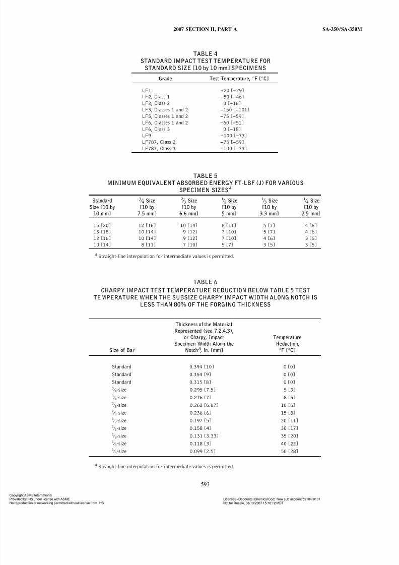
TABLE 4
STANDARD IMPACT TEST TEMPERATURE FOR
STANDARD SIZE [10 by 10 mm] SPECIMENS
Grade Test Temperature, °F [°C]
LF1 −20 [−29]
LF2, Class 1 −50 [−46]LF2, Class 2 0 [−18]
LF3, Classes 1 and 2 −150 [−101]
LF5, Classes 1 and 2 −75 [−59]
LF6, Classes 1 and 2 −60 [−51]
LF6, Class 3 0 [−18]
LF9 −100 [−73]
LF787, Class 2 −75 [−59]
LF787, Class 3 −100 [−73]
TABLE 5
MINIMUM EQUIVALENT ABSORBED ENERGY FT-LBF (J) FOR VARIOUS
SPECIMEN SIZESA
Standard 3 ⁄ 4 Size 2 ⁄ 3 Size 1 ⁄ 2 Size 1 ⁄ 3 Size 1 ⁄ 4 Size
Size [10 by [10 by [10 by [10 by [10 by [10 by
10 mm] 7.5 mm] 6.6 mm] 5 mm] 3.3 mm] 2.5 mm]
15 [20] 12 [16] 10 [14] 8 [11] 5 [7] 4 [6]
13 [18] 10 [14] 9 [12] 7 [10] 5 [7] 4 [6]
12 [16] 10 [14] 9 [12] 7 [10] 4 [6] 3 [5]
10 [14] 8 [11] 7 [10] 5 [7] 3 [5] 3 [5]
A Straight-line interpolation for intermediate values is permitted.
TABLE 6
CHARPY IMPACT TEST TEMPERATURE REDUCTION BELOW TABLE 5 TEST
TEMPERATURE WHEN THE SUBSIZE CHARPY IMPACT WIDTH ALONG NOTCH ISLESS THAN 80% OF THE FORGING THICKNESS
Thickness of the Material
Represented (see 7.2.4.3),
or Charpy, Impact Temperature
Specimen Width Along the Reduction,
Size of Bar NotchA, in. [mm] °F [°C]
Standard 0.394 [10] 0 [0]
Standard 0.354 [9] 0 [0]
Standard 0.315 [8] 0 [0]3 ⁄ 4-size 0.295 [7.5] 5 [3]
3 ⁄ 4-size 0.276 [7] 8 [5]2 ⁄ 3-size 0.262 [6.67] 10 [6]2 ⁄ 3-size 0.236 [6] 15 [8]1 ⁄ 2-size 0.197 [5] 20 [11]1 ⁄ 2-size 0.158 [4] 30 [17]1 ⁄ 3-size 0.131 [3.33] 35 [20]1 ⁄ 3-size 0.118 [3] 40 [22]1 ⁄ 4-size 0.099 [2.5] 50 [28]
A Straight-line interpolation for intermediate values is permitted.
593
yright ASME Internationalded by IHS under license with ASME Licensee=Occidental Chemical Corp New sub account/5910419101
Not for Resale, 08/13/2007 15:16:12 MDTeproduction or networking permitted without license from I HS

7/23/2019 Asme Section II a Sa-350 Sa-350m
http://slidepdf.com/reader/full/asme-section-ii-a-sa-350-sa-350m 10/12
SA-350 /SA-350M 2007 SECTION II, PART A
SUPPLEMENTARY REQUIREMENTS
In addition to any supplementary requirements of Specification A 961, the following supple-
mentary requirements shall apply only when specified by the purchaser in the order:
S1. Other Impact Test Temperatures
S1.1 Impact test temperatures lower or higher than the
standard temperature in Table 4 of this specification shall
be used.
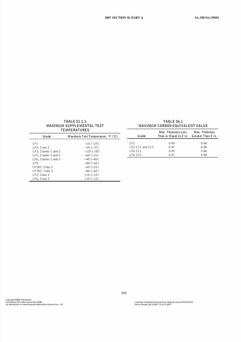
S1.1.1 When higher test temperatures are employed,
the actual test temperature may not be higher than that
given in Table S1.1.1.
S1.2 The test temperature shall be specified by the
purchaser. When subsize specimens are used, the manufac-
turer shall adjust the test temperature in accordance withthe size restrictions of 7.2.4.2 and 7.2.4.3.
S1.3 The forging shall be marked with the specified test
temperature in accordance with 15.4. A lower temperature
shall not be marked on the forging because of the use of
subsize specimens.
S1.4 The test results shall comply with Table 3 for
standard size specimens, and with Table 5 for subsize
specimens.
S2. Stress-Relieved Test Specimens
S2.1 The test specimens shall be stress relieved. Stress
relieving shall be done after heat treatment in 5.4 and
before machining the specimens from the heat-treated test
material.
S2.2 The purchaser shall furnish the forging manufac-
turer with details of the stress-relief treatment desired.
S3. Lateral Expansion
S3.1 Lateral expansion of the Charpy V-notch test in
accordance with Section 25 of Test Methods and Defini-
tions A 370 shall be measured and reported.
594
S4. Vacuum Carbon-Deoxidized Steels
S4.1 Material made to Grades LF1, LF2, LF3, LF5,
and LF9 shall be vacuum carbon-deoxidized, in which case
the silicon content shall be 0.12% maximum. The test
report shall indicate that the steel was vacuum carbon-
deoxidized.
S5. Special Impact Test Requirements for Flanges
(Note S5.1)
S5.1 Charpy test specimens shall be cut from an actualflange representing each size, heat, and heat-treatment lot.
If more than one size flange is represented by the same
heat and heat-treatment lot, the maximum size flange shall
be considered representative.
S5.2 The number, location, and orientation of the test
specimens shall be stated on the order.
S5.3 The test results shall comply with Table 3 for
standard size specimens, and with Table 5 for subsize
specimens.
NOTE S5.1 — These special requirements should be considered for
services when the applied stresses approach the maximum permissible
limits of the governing code, or the installation is subject to severe cyclic
conditions (7000 or more cycles over the expected life of the installation),
or both.
S6. Carbon Equivalent
S6.1 The maximum carbon equivalent based on heat
analysis shall be as shown in Table S6.1.
S6.2 Determine the carbon equivalent (CE) as follows:
CE p C + Mn/6 + (Cr + Mo + V)/5 + (Ni + Cu)/15
S6.3 A lower maximum carbon equivalent may be
agreed upon between the supplier and the purchaser.
yright ASME Internationalded by IHS under license with ASME Licensee=Occidental Chemical Corp New sub account/5910419101
Not for Resale, 08/13/2007 15:16:12 MDTeproduction or networking permitted without license from I HS
7/23/2019 Asme Section II a Sa-350 Sa-350m
http://slidepdf.com/reader/full/asme-section-ii-a-sa-350-sa-350m 11/12
2007 SECTION II, PART A SA-350 /SA-350M
TABLE S1.1.1
MAXIMUM SUPPLEMENTAL TEST
TEMPERATURES
Grade Maximum Test Temperature, °F (°C)
LF1 −10 [−23]
LF2, Class 1 −35 [−37]
LF3, Classes 1 and 2 −125 [−87]
LF5, Classes 1 and 2 −60 [−51]
LF6, Classes 1 and 2 −40 [−40]
LF9 −80 [−62]
LF787, Class 2 −60 [−51]
LF787, Class 3 −80 [−62]
LF2, Class 2 +10 [−12]
LF6, Class 3 +10 [−12]
595
TABLE S6.1
MAXIMUM CARBON EQUIVALENT VALUE
Max. Thickness Less Max. Thickness
Grade Than or Equal to 2 in. Greater Than 2 in.
LF1 0.45 0.46
LF2 CL1 and CL2 0.47 0.48
LF6 CL1 0.45 0.46
LF6 CL2 0.47 0.48
yright ASME Internationalded by IHS under license with ASME Licensee=Occidental Chemical Corp New sub account/5910419101
Not for Resale, 08/13/2007 15:16:12 MDTeproduction or networking permitted without license from I HS

7/23/2019 Asme Section II a Sa-350 Sa-350m
http://slidepdf.com/reader/full/asme-section-ii-a-sa-350-sa-350m 12/12
596
yright ASME International
--` ` ,` , ,` ` ` ,` ` , ,` ,` ,` ` ,` ,` ` ` , , ,-` -` , ,` , ,` ,` , ,` ---