Ask the Experts: Revit® MEP -...
24
Ask the Experts: Revit® MEP Speaker: Paul F. Aubin, Darryl A. McClelland, Martin Schmid and Gregg Stanley MP4483 Do you have a burning question about Autodesk Revit MEP? Join Paul, Gregg, Martin, and Darryl, the authors of the Aubin Academy Series Book on Revit MEP, for an interactive class focused on your issues. We want you to get the most from your Revit MEP software learning experience. No topic is off limits. Class begins when you sign up. We will email you before class to ask for your questions. We will come to the class with answers to all your emailed questions and be ready to take more questions as well. So if you want to participate in your own live Q&A class with the guys who wrote the book, join the authors for this informative Q&A session. The panel will include veteran author Paul F. Aubin, and industry experts and co-authors Darryl A. McClelland, Martin Schmid, and Gregg Stanley. Together they have nearly 80 years of building industry, architectural, and engineering experience. If these guys don't know the answer to your Revit MEP question, who will? Due to a restriction on the Autodesk University Website we were not able to email attendees for topics to be covered during class and added to the handout. We ask that you email [email protected] any Revit MEP questions and an updated handout will be posted on the class page 2 weeks after the class. Each question submitted will receive a reply with our thoughts. Sorry for any inconvenience Gregg Stanley, Darryl McClelland, Paul Aubin and Martin Schmid
Transcript of Ask the Experts: Revit® MEP -...

Ask the Experts: Revit® MEP Speaker: Paul F. Aubin, Darryl A. McClelland, Martin Schmid and Gregg Stanley
MP4483
Do you have a burning question about Autodesk Revit MEP? Join Paul, Gregg, Martin, and Darryl, the authors of the Aubin Academy Series Book on Revit MEP, for an interactive class focused on your issues. We want you to get the most from your Revit MEP software learning experience. No topic is off limits. Class begins when you sign up. We will email you before class to ask for your questions. We will come to the class with answers to all your emailed questions and be ready to take more questions as well. So if you want to participate in your own live Q&A class with the guys who wrote the book, join the authors for this informative Q&A session. The panel will include veteran author Paul F. Aubin, and industry experts and co-authors Darryl A. McClelland, Martin Schmid, and Gregg Stanley. Together they have nearly 80 years of building industry, architectural, and engineering experience. If these guys don't know the answer to your Revit MEP question, who will?
Due to a restriction on the Autodesk University Website we were not able to email attendees for topics to be covered during class and added to the handout.
We ask that you email [email protected] any Revit MEP questions and an updated handout will be posted on the class page 2 weeks after the class. Each question submitted will receive a reply with our thoughts.
Sorry for any inconvenience
Gregg Stanley, Darryl McClelland, Paul Aubin and Martin Schmid

Ask the Experts: Revit® MEP
2
About the Speakers: Paul F. Aubin is the author of many CAD and BIM book titles including the widely acclaimed: Aubin Academy Mastering Series: Revit Architecture and Aubin Academy Mastering Series: AutoCAD Architecture. Paul has also authored coauthored books on Revit and AutoCAD MEP and produced video training both on his website and as an author for lynda.com. Paul is an independent architectural consultant who travels domestically and abroad lecturing and providing Revit® Architecture and AutoCAD® Architecture implementation, training, and support services. Paul's involvement in the architectural profession spans 20 years, with experience that includes design, production, CAD management, mentoring, coaching, and training. He currently serves as Moderator for Cadalyst magazine's online CAD Questions forum, is an active member of the Autodesk user community, and has been a top-rated speaker at Autodesk University for many years. His diverse experience in architectural firms, as a CAD manager and as an educator, gives his writing and his classroom instruction a fresh and credible focus. Paul is an associate member of the American Institute of Architects. He lives in Chicago with his wife and three children.
Contact me directly from my website at: www.paulaubin.com
Darryl McClelland has 25 years of practical design experience in MEP engineering. Although his primary focus was the design of mechanical systems, he spent 11 of those 25 years designing electrical and plumbing systems as well. He also ran his own engineering business for eight years. His design experience ranges from complex research laboratories and institutional facilities to medical and professional office buildings, and everything in between. He is a graduate of Purdue University and an active member of ASHRAE, ASPE, and a LEED AP. Martin J. Schmid, P.E. has worked on-site with customers to implement best practices using AutoCAD MEP and Revit MEP, ranging from engineering firms and manufacturers to third party developers. In his current role as Industry Success Manager, Martin works with product management, product design, and quality assurance teams providing subject matter expertise. In addition, he works with sales and key accounts to help with workflow adoption and to identify technical trends. He has written and presented material on AutoCAD MEP and Revit MEP to coworkers as well as at Autodesk University. Prior to involvement with the development of MEP products, Martin worked in a variety of roles in a number of architecture and engineering firms, including electrical designer, engineering coordinator, and application developer. Martin has a master‟s degree in Architectural Engineering from Kansas State University and a master‟s in Business Management of Technology from the University of Texas in San Antonio, and is a member of ASHRAE. Martin has a beautiful wife and two daughters, and works from his home in San Antonio, TX. Gregg Stanley has over 24 years of experience in Mechanical Process Design focused on wastewater treatment systems. Gregg has also been in the position of a CAD Manager responsible for developing and instituting company-specific customized applications, BIM standards, and training. He has written and presented several training classes on AutoCAD, AutoCAD MEP, and Revit MEP both internally to coworkers, as an independent consultant and at Autodesk University. Gregg has also been in the position as a Quality Assurance Analyst and with Product design as a Piping Subject Matter Expert focused on AutoCAD MEP and Revit MEP focused on the Piping applications.

Ask the Experts: Revit® MEP
3
Introduction To accompany our panel discussion today, we have compiled this class paper. Questions in
paper were solicited from the attendees before the session. Hope you enjoy the session.
Questions from our Studio Audience: The following questions were solicited to the attendees signed up for the session as of mid
October. If your question was used, thank you very much. Our answers are provided after the
questions. Please note that even though some of us work for Autodesk, we can‟t address
future functionality.
Question from Trevor
Can the note symbol be place in the title bar of a Keynote Legend?
Yes! (and here is how)
To start with your notes might look like this

Ask the Experts: Revit® MEP
4
Step one is not actually in Revit. At your Windows Start menu type char map into the search
text box and run the Character Map program from there.
Choose the font you will be using and find the note symbol your firm uses. Now you are ready
to edit the schedule in Revit, but don't close Character Map yet ... you may need it again.
Working on the assumption that you wouldn't ask the question if you didn't know how to edit a
schedule the instructions jump forward a bit to the actual schedule editing.
On the Appearance tab of the Keynote Legend Properties dialog box, clear Show Title and
verify Show Headers is checked. (note... this isn't strictly necessary, you can make the note
symbol appear anywhere you want it but I think this is neater) Below is an example of the
format I use.

Ask the Experts: Revit® MEP
5
Next choose the Formatting Tab and in the Key Value Field Header paste the symbol into the
textbox.

Ask the Experts: Revit® MEP
6
In the Keynote Text Header type the title of your note legend. This is the result.
Which might be great for some people, but not me... I like my note headers in line with my
notes... and this is the reason that I use the header and not the title and the reason to leave the
Character Map program running. As everyone knows Revit loves to center Titles and Headers
and doesn't really give you the opportunity to change it. The work around I have found is again
in the Character Map. There are space characters that will allow you to fill out the header so
that it appears in line with your text. For this I use the En Space symbol U+2002. It takes
some practice and some thought... but the final product looks like this.
Question from Natalia Khaldi
I have a split floors. One side is higher than the other. I am using the plan region to override the
objects visibility. It seems like Plan region has trouble of “hiding” ducts and pipes (fittings do get
“hidden”)
Architect is issuing 4 floor plans, every floor has 4 plan regions … (not squared – free geometry)

Ask the Experts: Revit® MEP
7
Below is a schematic representation if the building . The Building is undisclosed so I cannot
even show correct geometry it is far from the box. One part of the building is an existing
building that will have some walls “stay” the rest is gone, the other part of the building is another
old building that stays but gets totally remodeled including façade, the third part is a new
Constriction. Multiuse 4 levels (about 15 different elevations for different slabs) Jalousie? Plan
region is working very well for the architect, but MEP portion of Revit is not doing what it
should. I‟ve got a phone call from…. I believe Christian from MEP team after the development
team look into the problem. It will require some heavy lifting re-programing to get it working on
MEP objects, so according to him it will be 2014 when it can go to the “box”. I ended up working
with partial plans and hatch regions to illuminate what I do not want to see….
The issue stems from how MEP elements are displayed in Revit. Normally, pipes and ducts will
always display if they are within the View Range (Top or Bottom) regardless of cut plane. For
Plan Regions, the View Range of the main view is "winning" so the ducts are not seeing the
View Range of the Plan Region.
The workaround at this time is to create two separate views and combine them on a sheet.
Question from: David Billion
How can I get Revit MEP to work with parallel equipment in piping systems? Example: Primary
and standby boilers in a heating water system or Primary and standby chillers in a cooling water
system.
Answer:

Ask the Experts: Revit® MEP
8
You do not need to define a system for the following functionalities:
1. Design and coordinate models.
2. Tabulate flows in the pipe network.
3. Use the pipe sizing tools.
For flow to work as expected, the key is in the connector on the equipment. In a
scenario where you have only one source equipment connection, typically, the
connector‟s Flow Configuration will be set to Calculated. For parallel flows, you need to
set this to “System.” If you then associate a parameter with the Flow Factor property of
the connector, you can modify the value in the project as necessary.
The following are examples of the supply side of the systems. This example shows
where the equipment operates simultaneously. The flow factor on both source
equipment is set to 0.5 to distribute the flow evenly between the equipment. If there
were three source equipment components, you would use 0.333. You don‟t need to use
equal values on the equipment, and they don‟t need to sum to 1.0.
This example shows where the equipment has a backup source equipment component:

Ask the Experts: Revit® MEP
9
You can even use the equipment with the connector defined as „System‟ if you only have
one source equipment:
The primary limitation with parallel flows has to do with pressure drop calculations. Revit
only computes the pressure drop up to the point where flows diverge (supply) or
converge (return). The following image shows the critical path of the pressure drop
calculation using system inspector. Note that the red arrows indicating the critical path
stop at the tee on the source equipment side of the network. The analysis of the
pressure drop across the parallel portion on the source equipment would require a
different algorithm.
Question from: David Billion

Ask the Experts: Revit® MEP
10
I have built duct and pipe fittings using lookup tables. I have built mechanical equipment using
type catalogs. I've tried on numerous occasions to use a lookup table when building mechanical
equipment. I always get an error message when filling in the formula. Question to the Experts:
Can I use a lookup table in mechanical equipment? Am I doing something incorrectly with the
equipment? Or, is it a function for fittings only?
Answer:
The text_file_lookup() function in family editor is only intended for pipe fittings. The
ConduitSize_Lookup() is only intended for conduit fittings. These functions return a
length value with one or more input length values.
For a more general approach, use Type Catalogs.
Question from: Jeff Lewis
Will Connectors be able to "talk to each other" thru linked files?
Answer:
The solution to this is new in 2011, using Copy/Monitor to copy lighting fixtures,
mechanical equipment, and plumbing fixtures between models.
Question from: Curtis Bockenstette
I don't understand the ref planes. I'm working thru Don Bokmiller's book Mastering
RevitMEP2011 and I seem to be missing something. I know that is a big question but right now
that is my Nemesis. Thanks Curtis
Answer:
References planes (and lines) are used to help constrain geometry. There is a really
good post on reference planes at the Revit OpEd blog:
http://revitoped.blogspot.com/2006/03/once-upon-reference-plane.html .
Question from: Abbie Meador
This is probably a simple question, but we are just at the beginning of learning and setting up
Revit MEP 2011. Is there an easy way to copy Filter settings only of one View Template to
another?
Answer:
You could create a view template that applies *only* the Visibility / Graphic Overrides
Filter settings, then use this strategically to continue defining your views and view
templates. Not a direct way, however, certainly better than defining all the filter settings
in each view template individually.

Ask the Experts: Revit® MEP
11

Ask the Experts: Revit® MEP
12
Questions from: Hai Le
Out-of-the-box vav boxes are created on Level 1. When placed, the boxes sit on the floor,
unless the user specify an offset. If a box is sitting at, say, 10ft offset, and ductwork is
subsequently connected, if the box size is changed (selection of a different family type), the box
"grows" or shrinks based on the bottom of the box, thus shifting the ductwork up or down. I tried
modifying the family to make the box centerline reference line IsReference and can then lock
the centerline of the box to a working plane. However, this works when swapping between some
types (sizes) but not all types. What is the best workaround to ensure ductwork do not move
when switching box sizes?
Answer:
There is no single magical approach. Some of the out of the box families have the
supply and return connectors constrained to the geometry such that they align with the
Ref. Level/Center(Elevation) reference plane, which then avoids the issue here.
However, not all manufactured components are like this… i.e., the outlet connector may
be „centered‟, but the inlet and/or return may be higher or lower, causing „disconnects‟
when sizes change.
Question:
Is there a way to force the use of flex duct to connect to air terminals as default when using
Connect Into or auto-routing? We've been using the command Convert to Flex or manually
making the final connection to the diffuser with flex.
Answer:
When using „Generate Layout‟, click the Settings… button on the options bar, and then
make sure a Flex Duct Type is specified.

Ask the Experts: Revit® MEP
13
Question:
What is the best way to branch ductwork vertically and horizontally using SMACNA type 4A and
4B divided flow branches? See image. (This is from SMACNA 2006).
Answer:
Beg/borrow/steal a multi-port fitting with very small length, one connector on one side,
and two connectors on the other:

Ask the Experts: Revit® MEP
14
Question from: Gabe Cottam
Why is it that direction that curtain wall's are drawn affect the perceived orientation of their glass
regardless of the orientation of their host wall?
For example:
1. Open a new file in Revit MEP 2011 x64
2. Draw a rectangle room with 4 generic 8” walls 20’ tall.
3. Draw 10’ tall curtain wall into the north wall FROM LEFT TO RIGHT (automatically embedded), in other words start in the northwest corner of the building and draw to the north east corner. (if the curtain wall is10’ cut in the other direction -counter clockwise- it seems to work just fine.)
4. Place a space in the room and change the upper limit offset to 12’.
5. Open gbxml export and change export complexity to Complex and click Save Settings.
6. Open Heating and Cooling Loads and click Analytical Surfaces. Notice the generic 8” wall to the north is considered a north wall, however the curtain wall cut out of the generic 8” wall to the north is considered south facing glass.
7. Change the Report Type to Detailed and click calculate. Scroll down to the space summary and notice there is a huge south window load although there is no south facing glass. Notice there is no north window load although there is north facing glass.
I've been trying to get a response from Autodesk through our local reseller for months. - no
answer yet.
Answer:
I was able to reproduce this issue. This has been logged as an issue for development to
investigate.
Question From: Chuck Geest
What is the common/best practice for linking shop drawings/O&M manuals to families in a
model and then turning over that model to the owner at the end of a project? If it is linking, do
the links get broken when the model is "transferred" to another computer system?
Answer:
There isn‟t a single „designed‟ feature for this, however, the URL parameter seems like
the logical choice. Just like any URL, the pathing (absolute/relative) needs to be
considered when inputting the data, and considerations need to be made how the data
will be structured on turn-over. It would be best at the start of the project to develop a
„communication specification‟ detailing the methods that will be employed.

Ask the Experts: Revit® MEP
15
Questions From: Keith Stearns
What is the best way to manage the warning "Elements have duplicate 'Mark' values?
Answer:
You could use the Model Review add-in to clear out the mark values and get rid of these
warnings.
Question:
Why can't I get pipe and duct to work with Plan Regions? (Fittings will.)
Answer:
It‟s not you; the developers haven‟t gotten this to work either.
Question:
Why do lights and diffusers become unhosted from the architectural plan when a new plan is
brought in, arch says that ceiling wasn't changed.
Answer:
This could be due to the configuration changing significantly and the elements are no
longer able to resolve where they should be. You could „investigate‟ by checking the
element id of the old ceiling and the new ceiling… if they are different, the arch
deleted/re-created the ceiling.
Question:
Is there a way to array connectors in a family? (I know arrays shouldn't be done.)
Answer:
Arrayed connectors wouldn‟t work as you would expect within the project context, and
therefore, arraying them appears to have been intentionally disabled.
Question:
Any tips for sloping pipe? :)
Answer:
Depends on what „issues‟ you‟re having.
Question:
Any tips for adding notes to the bottom of an equipment schedule, and no cheating doing a
second schedule?
Ask the Experts: Revit® MEP
16
Answer:
Sorry.
Question:
Flow arrows, any tips for this one? We can decide which way to go on this, Pipe Tag or generic
annotation.
Answer:
There is no designed functionality for this... tags or annotations seem to be the logical
choices.
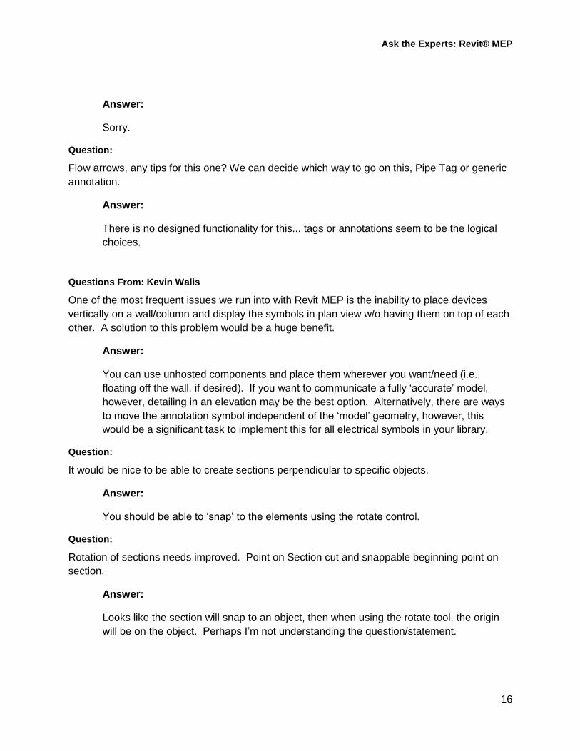
Questions From: Kevin Walis
One of the most frequent issues we run into with Revit MEP is the inability to place devices
vertically on a wall/column and display the symbols in plan view w/o having them on top of each
other. A solution to this problem would be a huge benefit.
Answer:
You can use unhosted components and place them wherever you want/need (i.e.,
floating off the wall, if desired). If you want to communicate a fully „accurate‟ model,
however, detailing in an elevation may be the best option. Alternatively, there are ways
to move the annotation symbol independent of the „model‟ geometry, however, this
would be a significant task to implement this for all electrical symbols in your library.
Question:
It would be nice to be able to create sections perpendicular to specific objects.
Answer:
You should be able to „snap‟ to the elements using the rotate control.
Question:
Rotation of sections needs improved. Point on Section cut and snappable beginning point on
section.
Answer:
Looks like the section will snap to an object, then when using the rotate tool, the origin
will be on the object. Perhaps I‟m not understanding the question/statement.

Ask the Experts: Revit® MEP
17
Questions From: Natalia Khaldi
Electrical Panel Board Schedules (Revit). State of California requires not only count of fixtures
on circuit but also how many are power, how many are lighting and how many are receptacles.
Would it be possible to add that information to the panel board in Revit.
Answer:
Yes, just not „automatically‟.
Question:
Plumbing (Revit) When connecting pipes at 45 deg. angle the Tee should be 45 but it does not
do it. The fitting looks “backwards”…
Answer:
Example?
Questions From: Dave Hostetter
How do we prevent custom families from being stolen from our Revit MEP models that may
make their way into competitor's hands? Is it possible to lock a model before sending it out to
the architect or other MEP firms?
Answer:
There is no technical solution to this. Generally, process is more important to
understand than result.
Question:
How do you create default schedules that are a part of a firm's MEP template?
Answer:
Define them in the template project. You can also use the tool on the Insert Tab >
Import Panel > Insert from File > Insert views from file to copy a schedule definition from
one project to another.
Question:
Can you customize how Revit MEP sizes pipes? Ex: 0-3 GPM = 3/4" Type L Copper pipe, 3.1-
6.5 GPM= 1" Type L Copper pipe, etc.

Ask the Experts: Revit® MEP
18
Answer:
No… except, of course, by manual methods. Using a schedule to back check would
probably be your best way to address this.
Question:
How do you get the automatic wiring feature in Revit to work with dual level switching for lights?
Answer:
Wiring does not have that level of intelligence.
Question:
How do you work around the differences in voltage classes? Ex: Using the standard 600V
disconnect on a 480V piece of equipment generates an error, but in reality this is what is used.
You can name the family „600v‟ disconnect, then have an instance param to define the
connection voltage (480, 277, 120, whatever…) There would be no bounds checking
that it is <= 600.
Question:
I have created a model in Revit MEP that I am using to do a solar study (shading analysis) on
PV panel design. When I view the shading in a 3D Top-down view the shading differs from the
shading on my roof plan view. The two views are analyzing the same time and date, yet the
shadows that are cast by the objects differ in length by 30% or so. So my question to you is
why is this happening?
Answer:
Is it possible that the two views are set to different North directions? In other words, is
one view set to Project North and the other to True North? It might possibly be another
setting in the time settings. Double-check that there is not a variation in the preset
applied to each view.
Question From: Marlon Pullins
Custom Ceiling. I have a ceiling that is 2' thick by 24' wide by 116' long. But here is where it gets
interesting. This ceiling has Holes in it. 12 holes equally spaced across. On the bottom part of
the ceiling the opening in square until it reaches the top where it goes more into a circle. How do
I create this ceiling? Then 2'above that ceiling is our suspended floor & in certain areas we have
pedestal legs that sit on the web of the original ceiling. Confused?
Maybe I can send you my AutoCAD ceiling so you may get a better understanding of this
ceiling.
Ask the Experts: Revit® MEP
19
Answer:
Sounds like you‟d need to use an in-place family.
Questions from: Damon J. Ranieri
How are other firms doing take-offs of their models to complete their static pressure
calculations?
Answer:
What methods did you employ prior to using Revit? This question seems to imply that
using Revit for this isn‟t working for you. What issues are you having?
Question:
How are other firms dealing with similar but not typical spaces? Copying areas of work is not as
simple as it was in CAD, what is the best approach?
Answer:
Copying becomes easier if you use unhosted content. Whether this is the best approach
or not is debatable.
Question:
Importing Revit information via gbXML only consistently gives us areas, and room/ zone name
and numbers, is anyone else able to make more use of the information exported via gbXML and
how?
Answer:
This would depend on what application you‟re importing the Revit exported gbXML into.
For example, exporting to Trane Trace includes information regarding lighting load,
occupancy, orientation, door/window opening areas, etc.
Question:
Is anyone else able to make use of the Electrical systems in Revit for anything other than
lighting circuits?
Answer:
Sure, circuiting receptacles, mechanical equipment, defining the electrical distribution,
generating panel schedules, etc.

Ask the Experts: Revit® MEP
20
Question:
How successful has everyone been with the Revit DB link? I have heard through anecdote
some firms have been able to change large sections of duct and pipe sizes in Excel and then
import the changes through the database link.
Answer:
I don‟t have any anecdotal data on this… though, I‟m not sure I understand why one
would want to size duct in a table driven database instead of in the graphical UI. Seems
like you could run into a lot of scenarios where you create conflicts, and „increasing‟ the
size of something could cause connections to break, particularly at fittings.
Questions from: Morty Zemedhun
How can I show multi section panels fed through lugs on a panel schedule?
Answer:
There is no „Subfeed Lug‟ option. You can increase the number of slots on the schedule
(i.e., for a 42 circuit panel, increase to 48), then clearly indicate that circuits 43,45,47
(and/or 44,46,48) are sub-feed lugs.
Question:
On existing job, how can I show Existing on a panel schedule? I know I can add Spares and
assign the circuit name to say "EXISTING”, but the problem with doing that is with the Load
Classification shown on the Load Summary. It will indicate „Spare” based on the Load
Classification name, and I don't know if there‟s a way to change that. Load will also be based on
the Demand Factor defined for “Spare” instead of “Existing Load”.
Answer:
Depends on how you want to show the data on the schedule. One option would be to
create a placeholder „electrical fixture‟, define a load category and demand factor called
„Existing Load‟, assign the load to the device, and connect the device to the panel. You
could do this on a „hidden‟ circuit (i.e., on slots 44,46,48), but set the schedule to only
show 42 slots. Your approach may depend on what the code review official wants to
see on the schedule for existing loads.
Question:
The batch copy feature works fine as long as I copy the architect's fixtures and add connectors.
How come Autodesk did not include the Revit MEP fixtures with Revit architectural? Are we
going to have same kind of capabilities with electrical devices.

Ask the Experts: Revit® MEP
21
Answer:
I don‟t know if Revit Architecture ships with the same content or not… chances are, not,
since they‟re more likely to use Ceiling or Wall hosted elements instead of Face Hosted.
in either case, chances are Architects are creating many lighting fixture families, and
don‟t „need‟ to include the connector info for their purposes.
Questions from: Chris Sullins
This question is in regards to structural coordination. These days we are typically asked to
coordinate our work above the plenum with the structure above. Architects routinely talk with the
assumption that this is easily accomplished. It may be easy to do this in Revit Architecture, but I
have not had much success in setting up a view to do this in Revit MEP. I usually wind up
having to create extra views and change many settings to see the structure, which normally
costs me the ability to see the architectural view correctly as a typical floor plan with partitions.
This process is not particularly quick, particularly in comparison to how long this would take to
do in AutoCAD. I have attempted to use the "Underlay" feature, to the best that I can see how it
works, but it does not seem to really control things the way I would expect it to work, and it
tends to affect the architectural background as well as the structure.
So my question is if we are looking at a particular floor plan that is set up how we want to see
the architecture, is there a practical way to see the location of the structure for the level above
without affecting the way the MEP elements and the architectural background appear? For the
purposes of this explanation, I would consider something practical if it could be accomplished
for a given view in about 30 seconds, at least to "activate" or "deactivate" the structure, meaning
that if it takes longer than that but could be incorporated into the initial project setup or view
template then that would also be practical.
Answer:
Once you have created view templates, it should take much less than 30 sections to
„activate‟ or „deactivate‟ the structure. Additionally, it is not uncommon to have „working
views‟ and „documentation views‟. For example, you may want to consider using a 3D
„slice‟ of the model to see the structure along with the duct system. You can still work in
plan, but be able to readily see where/if you have issues with structural conflicts.
Question:
This question is in regards to project setup. We are having much difficulty setting projects up in
ways that work throughout the project. As are many Revit MEP users, we are a multi-
disciplinary design firm that wishes to maintain consistency across trades. One difficulty we face
is the inability to align views on the sheet based on the contents of the view. We can at least
"eyeball" this to get close.

Ask the Experts: Revit® MEP
22
But the real problem is that sheets cannot be duplicated in the first place. Once I set up a sheet
for HVAC Sheetmetal, we need to be able to create an identical sheet for HVAC Piping,
Plumbing Pressure, Plumbing Drainage, Electrical Lighting, etc. It is possible that we could have
as many as 11 different versions of the same sheet for all the different trade. If we are working
in separate models, we can save some time creating the sheets for a couple of trades in one
model, and then changing those same sheets to match in another model. But this workaround is
time-wasting in itself, and still leaves much to be desired from the fact that you have to get one
model perfect before you can even create the other models to get them started.
Answer:
New in 2011 is the Guide Grid specifically developed to address this.
Question:
Other issues arise because the concept of BIM means that we are asked to begin working in
Revit when the architectural model is in the early stages of development.
Answer:
I don‟t think this is unique to BIM. In most cases of design, work has to begin before you
have all the information (whether designing a building, an airplane, or a tunnel through
the Andes Mountains)
Question:
Our clients do not have the time are the clairvoyance to set up their model in anticipation of all
the elements that will be needed for construction documents.
Answer:
The categories of elements is a set list.. so once you know what types of elements you
need in a view type (i.e., electrical lighting vs. power vs. hvac, etc), and you‟ve defined
what you need to see in a view, there should be no „surprises‟ with other elements of
unexpected categories showing up.
Question:
This means that commonly not all levels or views are set up in their model at this stage of
design. This makes it impossible for us to set up the project correctly at the beginning, which
means that all potential time savings gained will get lost when we inevitably have to set-up our
views 2 and 3 times over the course of the design.
Answer:
View templates should help here… of course, if there are levels not in the model during
the initial setup, you‟ll have to deal with those.

Ask the Experts: Revit® MEP
23
Question:
Has anyone come up with a better way of doing this? I recognize this could be an entire seminar
on its own, but there must be some way for us to improve productivity in this area.
Answer:
Since the nature of design is iterative, one never knows everything up front. Sounds as
though, generally, the main issue is communicating to the architect what you need to get
started on a project. Part of this is not knowing what you don‟t know yourself. Model
based design is a new paradigm, and as everyone gets more proficient, we‟ll wonder
how we ever communicated anything using only 2D primitive elements.
This would be a good topic to have an open discussion on.

Ask the Experts: Revit® MEP
24
Further Study You can find more information and tutorials in:
The Aubin Academy Master Series: Revit MEP 2012 and AutoCAD MEP 2012.
If you have any questions about this session or Revit MEP in general, you can use the contact form at
www.paulaubin.com to send me Martin, Darryl or Gregg an email.
Thank you for attending. Please fill out your evaluation.
Advertisement Thank you very much for attending our session today. If you would like to continue your learning
experience after the conference, please contact me to learn how Paul F. Aubin Consulting Services can
bring the learning to your office. Please visit my web site to learn how to purchase books or contact me
for a quote for onsite or virtual training, consulting and project coaching services.
Thank you!
The Aubin Academy Master Series:
Revit Architecture Essentials Training on lynda.com. For a FREE 24 hour pass, visit:
www.lynda.com/trial/paubin