ASIPP Overview of the first H mode and future plans of the ... · Y. R. Martin, T. Takizuka and...
44
ASIPP Overview of the first H mode and future plans of the superconducting tokamak EAST G. S. Xu on behalf of the EAST team and our international collaborators Institute of Plasma Physics Chinese Academy of Sciences ITPA & TTF meeting April 2011 Santiago
Transcript of ASIPP Overview of the first H mode and future plans of the ... · Y. R. Martin, T. Takizuka and...

ASIPP
Overview of the first H mode and future
plans of the superconducting tokamak
EASTG. S. Xu on behalf of the EAST team
and our international collaborators
Institute of Plasma Physics
Chinese Academy of Sciences
ITPA & TTF meeting April 2011 Santiago

ASIPP
EAST team and international collaborators
Institute of Plasma Physics, Chinese Academy of Sciences, Hefei, China : Jiangang Li, Baonian Wan, Yuanxi Wan, Xianzhu Gong, Bingjia
Xiao, Yuntao Song, Yu Wu, Jiafang Shan, Yanping Zhao, Liqun Hu, Yanfang Bi, Lei Cao, Jiafeng Chang, Yue Chen, Junling Cheng, Xu Deng,
Bojiang Ding, Siye Ding, Shijun Du, Yanmin Duan, Peng Fu, Jia Fu, Daming Gao, Ge Gao, Wei Gao, Xiang Gao, Shiying He, Yanlan Hu,
Liansheng Huang, Juan Huang, Zhensan Ji, Ming Jiang, Xiang Jie, Yinxian Jie, Jiahong Li, Yinyin Li, Shiyao Lin, Bili Ling, Fukun Liu, Saochen
Liu, Yong Liu, Peng Liu, Guangnan Luo, Zhengping Luo, Bo Lv, Dengkui Ma, Yuzhou Mao, Shengming Pan, Xuebing Peng, Jing Qian, Jinping
Qian, Chengming Qing, Pinjian Qing, Biao Shen, Linhai Sheng, Xiaoyang Sheng, Lan Shi, Yuejiang Shi, Xiaoyang Sun, Ang Ti, Xiaogang Wan,
Fudi Wang, Houying Wang, Huazhong Wang, Linsen Wang, Mao Wang, Shenming Wang, Xiaoming Wang, Yong Wang, Huiqian Wang, Keping
Wu, Hao Wu, Jiefeng Wu, Jinhua Wu, Junshuan Wu, Zhenwei Wu, Xiaoqi Xi, Weibing Xi, Chunyi Xie, Guosheng Xu, Huangdong Xu, Liuwei
Xu, Ping Xu, Tiejun Xu, Diye Xue, Ning Yan, Lei Yang, Zhongshi Yang, Chunyan Yuan, Qiping Yuan, Junyu Zhao, Qing Zhan, Ling Zhang,
Qiyong Zhang, Ruirui Zhang, Wei Zhang, Xiaodong Zhang, Xinjun Zhang, Fali Zhong, Guoqiang Zhong, Zhibo Zhou, Yanfei Zhu, Youhua Zhu,
Ping Zhu, Donghui Zhuang, Ming Zhuang
Donghua University, Shanghai, China : Jiarong Luo
South West Institute of Physics, Chengdu China : Qingwei Yang
Tsinghua University, Beijing, China : Zhe Gao
University of Science and Technology of China, Hefei, China : Adi Liu, Xiaoyuan Xu, Chanxuan Yu
General Atomic, San Diego, USA : Paul Anderson, Vincent Chan, Punit Gohil, Dave Humphreys, Al Hyatt, Lang L.Lao, Jim Leuer, Ali
Mahdavi, Gary Jackson ,Ben Penaflor, David Piglowski, Michael Schaffe , Mike Walker
Fusion Research Center, UT at Austin, USA : He Huang, Kenneth Gentle, Perry Philippe, William Rowan
Princeton Plasma Physics Laboratory, USA : R.Hawryluk, D.Mansfield, D.Mueller, M.Bitter, N.Fisch, K.W.Hill, D.M. Mastrovito, G.Fu ,
H.Qin , R.Wilson , L.Zakharov, M. Zarnstorff
Tri Alpha Energy, California, USA : Houyang Guo
Oak Ridge National Laboratory, USA : R. Maingi
National Institute for Fusion Sciences, Toki, Japan : H. Kasahara, R.Kumazawa, T.Mutoh , A. Naoko, H. Okada , K.Saito, Y. Shuichi , K.Toi,
T.Watari
Association Euratom-CEA, CEA Cadarache, France : A.Becoulet, B.Bremond, D. Douai,A.Ekedahl, T.Hoang, P.Huynh, Y.Peysson, K.Vueillie
Natiaon Fusion Research Institute, Korea Basic Science Institute, Daejeon, Korea : S.G.Lee, J.G.Bak
Association Euratom-RisøDTU, Denmark : V. Naulin, A.H. Nielsen, J. Juul Rasmussen
JET-EFDA, Culham Science Centre, UK : W. Fundamenski

ASIPP
Outline
I. Introduction of EAST
II. First H mode in the last campaign
H mode access
H mode performance
ELM characteristics
L-H transition
III. Future plans
IV.Summary

ASIPP
I. Introduction of EAST
Commenced operation in Sep. 2006
First H mode on 7 Nov. 2010, 23:16
Shot number 32525

ASIPP
Missions and achievements
EAST missions : 1MA, 20MW high-performance
steady-state operation (SSO).
1. Stationary H mode operation > 400 s
Achieved : 6.4 s H mode, HIPB98(y,2)~0.9
2. Long pulse divertor operation >1000 s
Achieved : 100 s L mode, Te0~1.2 keV
3. Plasma current up to 1.5 MA
Achieved : Ip = 1 MA, L mode
EAST parameters :
Major radius : R0 = 1.9 m
Minor radius : a = 0.5 m
Toroidal field : Bt = 3.5 T
Elongation : = 2
Triangularity : = 0.65
H mode
100 s
1 MA

ASIPP
II. First H mode : access
Commenced operation in Sep. 2006
First H mode in 7 Nov. 2010, 23:16
Shot number 32525

ASIPP
Conditions for H mode access
Power : LHCD 2.45GHz, 1.3MW (2MW), ~14% transmission line loss
ICRF 20-70MHz, 1MW, effective coupling < 0.5 MW
Control : RTEFIT/Isoflux control, SN, DN, limiter (2 removable limiter)
PFC : doped graphite tiles (~9000) with a ~100 m SiC coating
bolted to Cu heat sink, 2MW/m2
Wall conditioning : lithium evaporation and lithium powder injection
Pumping : In-vessel cryopump, pumping speed ~75.6 m3/s for D2
Fueling : gas puffing at different locations for various gas (D2, CD4, Ar, N2 …)
D2 working gas
Diagnostics : >40, for all key profiles
LHCD launcher
ICRF antenna
Removable limiter
Tile and Cu heat sink

ASIPP
Overview of the H mode shots
485 H mode shots in total
89% : POhm + PLHW including the first H mode discharge
duration 3.6 s, limited by Ip flat top durations
11% : POhm + PLHW + PICRF
duration 6.4 s, limited by discharge durations
51% : DN or unbalanced DN
16% : LSN (BB towards lower X-point)
33% : during configuration switches from DN to LSN
0% : USN
80% : first L-H transition during Ip flat top
16% : first L-H transition during Ip ramp-up
4% : first L-H transition during Ip ramp-down
Parameters at L-H :
Bt = 1.4~2 T
Ip = 0.4~0.8 MA
ne = 1.9~3.41019m3
PLHW = 0.5~1.1 MW
PICRF < 0.5 MW
SA = 38~42 m2
= 1.64~1.94
low = 0.45~0.58
q95 = 2.7~5.0

ASIPP
Key actions leading to the H mode
1. Wall conditioning by lithium coating : to reduce recycling, suppress impurities
and radiation.
2. Outer gap optimization by isoflux control and antenna position adjustment : to
improve LHW & ICRF power coupling and minimize impurity generation by the
plasma-antenna interaction.
3. Local gas puffing near the LHW launcher : to improve LHW coupling (not
routinely applied).
4. Shape the plasma into a divertor configuration early during Ip ramp-up : to
reduce impurities and radiation.
5. Increase the gas puffing rate during Ip ramp-up : to suppress runaway electrons.
6. Gas fueling from either the HFS or the domes : higher fueling efficiency than LFS
gas fueling.

ASIPP
LHW Power ~ 1MW
~ 0.6 during the H phase
Wave accessibility is good Wave deposition profiles
N|| ~2.1, spectral width ~0.2 TRANSP-LSC code
Strongly off-axis

ASIPP
LHW power coupling problem
Reciprocating Langmuir probe measurements
at the outer midplane showed that the ne and Te
in the SOL were significantly reduced in the
ELM-free phase, resulting in increased LHW
reflection.
Time history in SOL SOL profilesMultiple L-H-L transitions : when the applied LHW
power was marginal to the threshold.
H-L back transitions : increased power loss by
radiation & LHW reflection during ELM-free phases.

ASIPP
Improve LHW power coupling
To improve LHW coupling
the outer gap was optimized by isoflux plasma
boundary control and antenna position adjustment.
local gas puffing near the LHW launcher.
Reflection coefficient < 10%

ASIPP
Wall conditioning: Siliconization
30 min Siliconization + 35 min He-ICRF
15kW, 0.05 Pa, 1s on/1s off
using a gas mixture of SiD4:He = 1:9
Wall temperature ~ 70 ℃
This deposition technique suppressed
both O and C impurities but did little
to reduce either recycling or H/(D+H).
As a result no access to the H-mode
was achieved using wall conditioning
with silicon.

ASIPP
Wall conditioning: Li evaporation
oven
oven
lithium coated area
lithium coated area
300 ℃ 475 ℃
GDC or ICRF lithium coating
Li evaporation has been conducted 67 times.
Nearly 1 kg of Li has been injected into the
vessel through evaporation.
Before Li conditioning, bake-out of PFCs up
to 240 ℃ to reduce their hydrogenic loading.
Two ovens at outer midplane
10~30 g, evaporated at 500~550 ℃, 1~2 hours
Usually assisted by helium GDC or ICRF
discharge.

ASIPP
Wall conditioning: Li powder droplet
Real-time injection of fine lithium powder into the plasma edge : A collaboration with PPPL
D. K. Mansfield et al., Fusion Eng. Des. 85, 890 (2010)
Dropper ~50 mg/s
6.4 s H mode
~500 shots, ~30% of H-mode shots, 40g

ASIPP
Effects of lithium wall coating
The first H-mode plasma was achieved after
evaporation of 34 g of Li and 17 shots with Li powder
injection.
H/(D+H) ratio : ~50% ~7% in plasmas with
deuterium fueling, Li accumulated to > 50 g.
Isotope scaling : help to reduce the power threshold.
Improve ICRF heating efficiency.

ASIPP
II. First H mode : performance
Commenced operation in Sep. 2006
First H mode on 7 Nov. 2010, 23:16
Shot number 32525
ASIPP
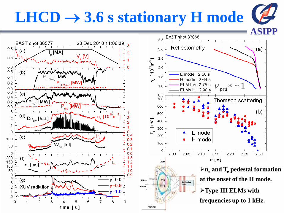
LHCD 3.6 s stationary H mode
ne and Te pedestal formation
at the onset of the H mode.
Type-III ELMs with
frequencies up to 1 kHz.
~ 1ped

ASIPP
XUV profiles indicate pedestal formation
The formation of pedestal was further confirmed by a sharp rise in the XUV
(extreme ultra-violet) radiation at plasma edge.

ASIPP
X-point neutral density reduced by 4
~21017m3 ~51016m3
High recycling Low recycling
Visible CCD camera, at the same ne

ASIPP
H mode threshold power scaling 1:1
0.72 0.80 0.94
200.0488thresh e t AP n B S
loss aux Ohm rad diaP P P P dW dt
Threshold power of EAST LHCD H modes is aligned with predictions of the international
tokamak scaling
A threshold in density for H-mode access has been identified :
Didn't see density rollover
19 31.9 10en m
Y. R. Martin, T. Takizuka and ITPA CDBM H-mode Threshold
Database Working Group, J. Phys.: Conf. Ser. 123, 012033 (2008).
EAST

ASIPP
Power threshold comparisons
Similar power threshold for DN & LSN
LSNDN
Similar power threshold for Ip ramp up and flat top
Lower power threshold for Ip ramp down
Ip

ASIPP
LHCD H mode energy confinement
exp
E dia lossW P
89 0.85 0.2 0.5 0.1 0.5 1.5 0.3 0.50.048ITER P
E p tI B P n A R
98 ,2 0.93 0.15 0.69 0.41 0.19 1.97 0.58 0.780.145IPB y
E p tI B P n A R
HITER89-P 2 HIPB98(y2) 1.1

ASIPP
LHCD H mode HIPB98(y,2) is up to ~1
exp
E dia lossW P
Dwell time of L-H transition Triangularity dependence
Power dependence Density dependence

ASIPP
LHCD + ICRF 6.4 s H mode
LHCD was applied very early during Ip
ramp-up to assist target plasma build up,
enhance plasma temperature, so as to
improve ICRF heating efficiency.
The H mode duration was limited only by
presently attainable discharge durations.
It can be very easily extended to more
than 10 s when the LHW power is
upgraded in the next campaign.
ICRF at 27MHz in minority heating
dominated regime (~0.5 MW was
absorbed). Optimized coupling by
controlling density and the gap between
separatrix and antenna.

ASIPP
II. First H mode : ELM characteristics
Commenced operation in Sep. 2006
First H mode on 7 Nov. 2010, 23:16
Shot number 32525

ASIPP
ELM average heat load ~ 2MW/m2
IR CCD camera, 20 ms time resolution
Type III ELMs

ASIPP
In-out asymmetry in target heat load
LSN
Type III ELMs
LSN, dRsep = 1 cm
Inner > Outer
IR CCD data IR CCD data
DN
Type III ELMs
DN, dRsep = 0 cm
Outer > Inner

ASIPP
Energy loss by ELM W/W = 1~2%
1 ~ 2%div
ELM
dia
W
W
2kJdiv
ELMW
Target probes
LSN & DN

ASIPP
Type I like irregular isolated ELMs
Big ELMs caused energy
loss > 5% of stored energy
Target peak heat load >
3MW/m2
Deposited energy on
divertor plates > 3kJ
H mode was sustained by
0.3 MW as a result of the
hysteresis effect.

ASIPP
ELM control by Argon seeding
Argon gas was injected
from lower outer target at
a speed of 41020 particles/s
ELM frequency rises
ELM amplitude decreases
ELM duration decreases
Prad didn’t increase
Ploss increased
Wdia decreased

ASIPP
B
thodographs (Br B B )
The frequency of ELM
precursor decrease
from 130kHz to 60kHz
during 0.4ms
Type III ELM
2~ 1.5filj MA m
ELM precursor and current filament
Moveable, 3D pickup
coils & probes
In the SOL and edge
1cm < r < 10 cm

ASIPP
Negative D spikes near X-point
Inner target X-point
Ionization
region
High densityen 4
Not detached at the inner target

ASIPP
Mossy ELMs ~ 300 ms duration
XUV radiation

ASIPP
Alfven-like modes in ELM-free phase
Spectrum Phase
Alfven-like modes at frequency ~300kHz and ~30kHz
were sometimes detected by reciprocating mid-plane
probes during ELM-free phases.
Ddiv

ASIPP
II. First H mode : L-H transition
Commenced operation in Sep. 2006
First H mode on 7 Nov. 2010, 23:16
Shot number 32525

ASIPP
GAM disappear during H mode
Reciprocating probe data at the plasma
edge show GAM oscillation in L mode
but it disappeared in H mode.

ASIPP
Dithering just before L-H transition
D at inner target
Isat at outer target
Dithering was frequently observed just before L-H transition
or sometimes in L mode when ne>2, L-H precursor ?

ASIPP
III. Future plans
Commenced operation in Sep. 2006
First H mode on 7 Nov. 2010, 23:16
Shot number 32525

ASIPP
Plans for next 5 years
2011 2012 2013 2014 2015
Ip(MA) 1.0 1.0 1.0 1.5 1.5
LHCD(MW, CW)
2.45GHz 4.0 4.0 4.0 4.0 4.0
4.6GHz 6.0 6.0 6.0
ICRF(MW,CW)
20-75MHz 4.5 4.5 4.5 4.5 4.5
30-100MHz 1.5 4.5 4.5 4.5 4.5
NBI(80keV) 4.0 4.0 8.0
ECRH(140GHz, CW) 2.0 4.0 6.0 6.0
PFC Mo/C Mo/W/C Mo/W Mo/W W
Diagnostics 40 45 50 50 50
Duration(s) 100 200 300 400 500
t-Hmode(s) 30 60 100 200 400
With over 20MW CW power and > 50 diagnostics, EAST could play a key role
for long pulse advanced high performance plasma for ITER within next 5 years.

ASIPP
Liquid lithium limiter and divertor
2011, Liquid lithium limiter on HT-7
2014, Liquid lithium divertor on EAST

ASIPP
IV. Summary
Commenced operation in Sep. 2006
First H mode on 7 Nov. 2010, 23:16
Shot number 32525

ASIPP
Summary of the EAST first H mode
3.6 s stationary ELMy H mode with HIPB98(y,2) up to ~1 has been achieved
with only 1 MW of LHCD.
6.4 s stationary ELMy H mode has been achieved with 1 MW LHCD +
0.5 MW ICRF.
The threshold power for H-mode access follows the international
tokamak scaling and a threshold in density has been identified.
Strong effects due to lithium deposition and accumulation on the H-mode
access and performance have been observed. A likely contributing factor
is the lower edge recycling produced by lithium pumping as indicated by
a significant drop in the neutral density near the lower X-point.
More than 20 MW power and 50 diagnostics will be ready in next 3 years.
Steady-state H mode with 100 s duration will be achieve in next 3 years.

ASIPP
EAST is a open collaboration platform for
the world!
Welcome to join EAST experiments.
Thank you very much for your attention!
Our campus