ASHRAE GUIDELINE Specifying Direct Digital Control Systems Library/Technical... · DDC systems...
21
ASHRAE GUIDELINE ASHRAE GUIDELINE American Society of Heating, Refrigerating and Air-Conditioning Engineers, Inc. 1791 Tullie Circle NE, Atlanta, GA 30329 www.ashrae.org Specifying Direct Digital Control Systems Addendum a to ASHRAE Guideline 13-2000 Approved by the ASHRAE Standards Committee on June 25, 2005, and by the ASHRAE Board of Directors on June 30, 2005. This guideline is under continuous maintenance by a Standing Guideline Project Committee (SGPC) for which the Standards Committee has established a documented program for regular publication of addenda or revisions, including procedures for timely, documented, consensus action on requests for change to any part of the guideline. The change submittal form, instructions, and deadlines may be obtained in electronic form from the ASHRAE Web site, http://www.ashrae.org, or in paper form from the Manager of Standards. The latest edition of an ASHRAE Guideline may be purchased from ASHRAE Customer Service, 1791 Tullie Circle, NE, Atlanta, GA 30329-2305. E- mail: [email protected]. Fax: 404-321-5478. Telephone: 404-636-8400 (worldwide), or toll free 1-800-527-4723 (for orders in US and Canada). ©Copyright 2005 ASHRAE, Inc. ISSN 1049-894X
Transcript of ASHRAE GUIDELINE Specifying Direct Digital Control Systems Library/Technical... · DDC systems...

ASHRAE GUIDELINEASHRAE GUIDELINE
American Society of Heating, Refrigeratingand Air-Conditioning Engineers, Inc.
1791 Tullie Circle NE, Atlanta, GA 30329www.ashrae.org
Specifying DirectDigital ControlSystems
Addendum a to ASHRAE Guideline 13-2000
Approved by the ASHRAE Standards Committee on June 25, 2005, and by the ASHRAE Board of Directors on June30, 2005.
This guideline is under continuous maintenance by a Standing Guideline Project Committee (SGPC) for which theStandards Committee has established a documented program for regular publication of addenda or revisions,including procedures for timely, documented, consensus action on requests for change to any part of the guideline.The change submittal form, instructions, and deadlines may be obtained in electronic form from the ASHRAE Website, http://www.ashrae.org, or in paper form from the Manager of Standards. The latest edition of an ASHRAEGuideline may be purchased from ASHRAE Customer Service, 1791 Tullie Circle, NE, Atlanta, GA 30329-2305. E-mail: [email protected]. Fax: 404-321-5478. Telephone: 404-636-8400 (worldwide), or toll free 1-800-527-4723(for orders in US and Canada).
©Copyright 2005 ASHRAE, Inc.
ISSN 1049-894X

SPECIAL NOTE
This Guideline was developed under the auspices of the American Society of Heating, Refrigerating and Air-ConditioningEngineers (ASHRAE). ASHRAE Guidelines are developed under a review process, identifying a guideline for the design, testing, appli-cation, or evaluation of a specific product, concept, or practice. As a guideline it is not definitive but encompasses areas where theremay be a variety of approaches, none of which must be precisely correct. ASHRAE Guidelines are written to assist professionals in thearea of concern and expertise of ASHRAE’s Technical Committees and Task Groups.
ASHRAE Guidelines are prepared by project committees appointed specifically for the purpose of writing Guidelines. Theproject committee chair and vice-chair must be members of ASHRAE; while other members of the project committee may or may notbe ASHRAE members, all must be technically qualified in the subject area of the Guideline.
Development of ASHRAE Guidelines follows procedures similar to those for ASHRAE Standards except that (a) committeebalance is desired but not required, (b) an effort is made to achieve consensus but consensus is not required, (c) guidelines are notappealable, and (d) guidelines are not submitted to ANSI for approval.
The Manager of Standards of ASHRAE should be contacted fora. interpretation of the contents of this Guideline,b. participation in the next review of the Guideline,c. offering constructive criticism for improving the Guideline,d. permission to reprint portions of the Guideline.
ASHRAE INDUSTRIAL ADVERTISING POLICY ON STANDARDSASHRAE Standards and Guidelines are established to assist industry and the public by offering a uniform method of
testing for rating purposes, by suggesting safe practices in designing and installing equipment, by providing proper definitions of this equipment, and by providing other information that may serve to guide the industry. The creation of ASHRAE Standards and Guidelines is determined by the need for them, and conformance to them is completely voluntary.
In referring to this Standard or Guideline and in marking of equipment and in advertising, no claim shall be made, eitherstated or implied, that the product has been approved by ASHRAE.
DISCLAIMER
ASHRAE publishes Guidelines in order to provide assistance to interested parties on issues that relate to the design, testing,application, and/or evaluation of products, concepts, and practices where there may be more than one acceptable approach.Guidelines are not mandatory and only provide one source of information that may be helpful in any given situation.
ASHRAE STANDARDS COMMITTEE 2004-2005
Dean S. Borges, ChairRichard D. Hermans, Vice-ChairDonald B. BivensPaul W. CabotHugh F. CrowtherBrian P. DoughertyHakim ElmahdyMatt R. HarganRoger L. HedrickJohn F. HoganFrank E. JakobStephen D. KennedyDavid E. Knebel
James D. LutzMerle F. McBrideMark P. Modera
Cyrus H. NasseriDavor Novosel
Stephen V. SantoroGideon ShavitDavid R. TreeBede Wellford
James E. WoodsMichael F. Beda, BOD ExO
William A. Harrison, CO
Claire B. Ramspeck, Manager of Standards
ASHRAE Standing Guideline Project Committee 13Cognizant TC: TC 1.4, Control Theory and Application
SPLS Liaison: Donald B. Bivens
Steven T. Taylor, Chair*
Chariti A. Young, Vice-Chair*
David L. Brooks*
Paul W. Ehrlich*
John A. Hendrix, Jr.*
David B. Kahn*
James R. Kelley*
Christopher L. Mellen*
John J. Santos*
Gideon Shavit*
Grant N. Wichenko*
James R. Winston*
*Denotes members of voting status when the document was approved for publication

[This foreword is not part of the guideline. It is merely
informative and does not contain requirements necessary
for conformance to the guideline.]
FOREWORD
This addendum incorporates editorial changes and minorindependent substantive changes (ISCs) to the current pub-lished version of the guideline. These changes are indicated inthe text by underlined blue type (for additions) andstrikethrough (for deletions).
Addendum a to ASHRAE Guideline 13-2000
Correct the spelling error in Section 4.4.4 as indicated.
Categories of Protocols. The word standard is often usedin discussions of protocols. There are “degrees of propriety”to the standards continuum, and they can be explained asfollows:
• Industry recognized standard—A protocol that is for-mally recognized and/or listed by an independent,industry standards organization as a set of operationalcriteria. Examples are BACnet (recognized byASHRAE and ANSI) and LonTalk (EIA).
• Defect Defacto standards—Very popular proprietaryprotocols in the marketplace that have been embracedby users and manufacturers and are offered as communi-cations options on a variety of equipment. Examples areModBus, Allen Bradley DH+, and Opto 22.
• Proprietary standards—A manufacturer makes propri-etary protocols available on a limited basis or shares theprotocol with the public at large for use in integratingother products into that manufacturer’s network.
These classifications may be helpful in understanding thetype of endorsement and support a protocol may have but donot suggest how popular or how broad the base of users maybe. Some protocols of major control system manufacturers arealso implemented by a defined, but limited, number of othermanufacturers to bring a broad-based, interoperable solutionto the market. The size of that number may exceed the numberof solutions possible through the use of an industry recognizedor defacto standard.
Make the following editorial correction in Section 5.3.3.
The sequences should detail how the system operates ineach mode—e.g., normal, occupied, summer, winter, andemergency. The system operation under safety trips, smokecontrol, and fire shutdown all must be defined. All setpointsand operating points also should be defined in the sequence.
Revise Section 7 as shown below and on the following
pages.
7. SPECIFICATION PART 1: GENERAL
This part of the specification covers administrative issuessuch as system performance, approvals, and submittals. Thesubsequent parts of the specification—Products and Execu-tion—are discussed in Clauses 8 and 9, respectively.
This specification section must be edited to reflect para-graphs and titles used in an actual project specification.
1.0 SECTION INCLUDES
.1 Products Furnished bBut Not Installed uUnderThis Section
.2 Products Installed Bbut Not Furnished uUnderThis Section
.3 Products Not Furnished or Installed under butIintegrated with the Work of This Section
.4 Related Sections
.5 Description
.6 Approved Control System Contractors and Manu-facturers
.7 Quality Assurance
.8 Codes and Standards
.9 System Performance
.10 Submittals
.11 Warranty
.12 Ownership of Proprietary Material
7.1 Products Furnished bBut Not Installed uUnder This
Section
There are a variety of products furnished by a controls
subcontractor that are best installed by another subcontractor
within the construction team. “Best installed” means that the
cost of installation and/or coordinating labor is typically
reduced if specified for installation by another. These products
include pipe-mounted devices that are best installed by the
piping subcontractor and certain duct devices (e.g., dampers)
that are best installed by the sheet metal subcontractor. This
specification paragraph should be edited to list only those
other specification sections that include installation instruc-
tions for the products involved. (See Clause 10, “Instructions
to Other Contractors,” for more information on these installa-
tion instructions.)
Project Considerations: The paragraph should be
stricken for projects in which the controls subcontractor may
be the prime contractor (e.g., a controls upgrade project).
Also, the specifier needs to complete the listed section
numbers (shown below as “15xxx”) and edit the titles to match
the actual sections used within the remainder of the specifica-
tion.
1.1 PRODUCTS FURNISHED BUT NOT INSTALLED UNDER THIS SECTION
A. Section 15xxx—Hydronic Piping: 1. Control Valves2. Flow Switches 3. Temperature Sensor Wells and Sockets4. Flow mMeters
B. Section 15xxx—Refrigerant Piping: 1. Pressure and Temperature Sensor Wells and
SocketsC. Section 15xxx—Ductwork Accessories:
1. Automatic Dampers2. Airflow Stations3. Terminal Unit Controls
Addendum a to ASHRAE Guideline 13-2000 1

7.2 Products Installed bBut Not Furnished uUnder This
Section
A variety of HVAC equipment can be specified with
manufacturer-furnished controls. This approach will become
more common as the use of standard protocols permits inte-
gration of manufacturer-furnished DDC controllers into a
single system. (Refer to Clause 10 for further discussion of the
integration of these controls with the rest of the communica-
tion network.) Some of the controls furnished by an HVAC
equipment manufacturer may require field installation efforts,
for example, a space thermostat provided with a packaged air
handler.
Project Considerations: This specification paragraph
should be edited to list only those other specification sections
that include products for installation under this section. The
paragraph should be stricken for projects in which the controls
subcontractor is the prime contractor (e.g., a controls upgrade
project). Finally, the specifier needs to complete the listed
section numbers (shown below as “15xxx”) and edit the titles
to match the actual sections used within the remainder of the
specification.
1.2 PRODUCTS INSTALLED BUT NOT FURNISHED UNDER THIS SECTION
A. Section 15xxx—Refrigeration Equipment:1. Refrigerant Leak Detection System
B. Section 15xxx—Rooftop Air-Handling Equipment:1.Thermostats2. Duct Static Pressure Sensors
7.3 Products Not Furnished or Installed under but Inte-
grated with the Work of This Section
DDC systems increasingly are relying on controls
provided by a variety of subcontractors and/or suppliers to
form an overall building automation system. These other
controls range from chiller and boiler controls to non-HVAC
controls such as fire alarm systems, fire/smoke dampers, and
lighting control systems. If the building automation system
design requires functions that involve the sharing of informa-
tion between these various controls—or just some type of
simple interlock—then it can be said that the DDC system is
integrated with these other controls. Following are examples
of functions that require integration.
• A boiler plant can use a digital output from the DDC
system to enable/disable a boiler sequencing controller
provided by the boiler manufacturer.
• Chiller setpoint reset can involve the output of an analog
signal from the DDC system to the chiller controller
provided by the chiller manufacturer. With a standard
protocol such as BACnet, this can be handled through a
communications network.
• A VAV terminal unit can be provided with a cross-flow
velocity sensor that is used with a field-installed DDC
controller for pressure independent control.
• Duct smoke detectors are typically interlocked by the
controls subcontractor to the air handler for life safety
shutdown.
• Fire/smoke dampers may be supplied with pneumatic
actuators and therefore require control air to be supplied
by the controls subcontractor.
• Smoke control can require extensive integration
between the DDC system and the fire alarm system if
the HVAC system is involved in smoke control.
• An HVAC system can be started and stopped based on a
security system’s card reader transactions.
• Operation of both HVAC and lighting controls from the
same time schedule residing in either system.
The suppliers and/or subcontractors involved with the
other systems should be both supplying and installing those
systems. However, the various members of the construction
team need to coordinate their efforts to successfully integrate
the controls. The purpose of this paragraph is merely to direct
the reader to these other controls. Other portions of the project
design need to provide the details of this integration, includ-
ing:
• this specification, Part 3: “Coordination”;
• the DDC system drawings and sequences of operation,
which should describe the functions required;
• the other sections of the specification (including other
divisions), which should be edited to include reciprocal
discussions of the integration required. (Again, refer to
Clause 10 for discussion about wording to be included
in these sections.)
Project Considerations: The following specification
paragraph should be edited to include only the other specifi-
cation sections that apply to the integration involved. Also, the
specifier needs to complete the listed section numbers (shown
below as “15xxx”) and edit the titles to match the actual
sections used within the remainder of the specification.
Finally, a detailed discussion of the integration required
should be included in Part 3, “Sequences of Operation.”
1.3 PRODUCTS NOT FURNISHED OR INSTALLED UNDER BUT INTEGRATED WITH THE WORK OF THIS SECTION
A. Section 15xxx—Heat Generation Equipment:1. Boiler Controls
B. Section 15xxx—Refrigeration Equipment:1. Chiller Controls
C. Section 15xxx—Rooftop Air-Handling Equipment: 1. Discharge Air Temperature Control2. Economizer Control3. Volume Control
D. Section 15xxx—Unit Ventilators and Fan Coil Units:1. Set Point Reset2. Day/ and Night Indexing
E. Section 15xxx—VAV Terminal Units:1. Cross-Flow Velocity Sensor
F. Section 15xxx—Variable Frequency Drives
2 Addendum a to ASHRAE Guideline 13-2000

7.4 Related Sections
Controls are typically field-installed on a variety of
mechanical and other equipment. The installation efforts of
other subcontractors must be coordinated with the efforts of
the controls subcontractor. Therefore, this section should be
used to direct the reader to all other portions of the specifica-
tion that include equipment to be controlled by—or coordi-
nated with—the DDC system. There may be a variety of
specification sections outside the mechanical and electrical
divisions that should be identified here, including kitchen
equipment, fume hoods, irrigation systems, etc. These will
depend on the level of building automation desired. This
section also reminds the controls subcontractor that it is also
subject to the general project terms and conditions found in
Divisions 0 and 1.
Project Considerations: This section needs to be edited
to list the actual sections and their titles used in the project
specification.
1.4 RELATED SECTIONS
A. The General Conditions of the Contract, Supple-mentary Conditions, and General Requirements area part of this specification and shall be used inconjunction with this section as a part of the contractdocuments. Consult them for further instructionspertaining to this work. The Contractor is bound bythe provisions of Division 0 and Division 1.
B. The following sections constitute related work:
1. Section 01xxx—Submittal Requirements
2.1. Section 01xxx—Commissioning
3.Section 13xxx—Security Access and Surveillance
4.Section 13xxx—Detection and Alarm
5.2. Section 15xxx—Basic Mechanical Require-mentsMaterials and Methods
6.Section 15xxx—Heat Generation Equipment
7.3. Section 15xxx—Refrigeration Equipment
8.4. Section 15xxx—Air-HandlingHeating, Ventilating,and Air-Conditioning Equipment
9.Section 15xxx—Air Distribution
10.5.Section 15xxx—Testing, Adjusting, and Balan-ceing
11.6.Section 16xxx—Basic Electrical Requirements-Materials and Methods
7. Section 16xxx—Basic Electrical Materials
12.8.Section 16xxx—General Wiring Methods
13.9.Section 16xxx—Equipment and Motor Wirin-gElectrical Power
14.Section 16xxx—Low-Voltage Distribution
10. Section 16xxx—Fire Alarm System11. Section 16xxx—Security Systems12. Section 16xxx—Uninterruptible Power Supply13. Section 16xxx—Emergency Systems
7.5 Description of DDC System
This section should contain a narrative description of the
system. This description could include the type of architec-
ture, communication technology, panel layout, use of DDC vs.
conventional controls, operator interfaces, and any special or
unusual hardware or operating features. The purpose is to
provide the reader with insight into the design intent. This
section should be an overview of the project, highlighting any
special requirements associated with its implementation. It is
not meant to describe every detail of the control system design
and installation.
Project Considerations: This section should be edited to
describe the project.
1.5 DESCRIPTION
A. General: The control system shall be as shown andconsist of a high-speed, peer-to-peer network ofDDC controllers and an operator workstation. Theoperator workstation shall be a personal computer(PC) with a color monitor, mouse, keyboard, andprinter. The PC will shall allow a useroperators tointerface with the network via dynamic color graph-ics. Depict Eeach mechanical system, building floorplan, and control device will be depicted by a point-and-click graphics. Furnish Aa modem will beprovided or network interface card for remoteaccess to the network and for paging the operatorswhen an alarm occurs.
B. The system will directly control each air-handlingunit by maintaining discharge air temperature, ductand building static pressure, and outside air econo-mizer control. The hot water boiler and pumpingsystem will operate to reset the hot water supplytemperature based upon outside air temperatureand pump lead-lag control. The chiller and chilledwater pump system will operate based on outside airtemperature and pump lead/lag control. In addition,each terminal variable air volume (VAV) and fan-powered VAV unit will be controlled by individualDDC zone controllers networked with the primaryDDC panels. Each zone controller will provide foroccupied/unoccupied mode of operation by individ-ual zone. For energy conservation, the system willbe programmed for optimal Start/Stop of the air-handling units and hot and chilled water systems,night setback, and night purge control.
C. The system will pProvide for future system expan-sion to include monitoring of the occupant cardaccess, fire alarm, and lighting control systems.
7.6 Approved Control System Contractors and Manu-
facturers
7.6.1 General
The controls subcontractor chosen for the project is
perhaps the single most important factor in the successful
implementation of a DDC system. This is contrary to other
specification sections where the emphasis is placed on manu-
facturers. Therefore, to help control the quality of the subcon-
tractor chosen, it is good practice to limit the list of allowable
Addendum a to ASHRAE Guideline 13-2000 3

bidders. Pre-qualification efforts can range from using a list of
familiar subcontractors to undertaking a major pre-qualifica-
tion effort. The issues considered might include the subcon-
tractor’s reputation, the quality of the subcontractor’s
documentation, the level of customer training provided, and
history of service performance. Be advised that these issues
can change over time for a specific subcontractor.
The list of approved controls subcontractors does not
preclude the possibility that other controls subcontractors or
DDC manufacturers may win the project. The specifier should
review other sections or divisions of the specification for the
rules concerning substitutions and prior approvals.
Technical ProposalsAn alternative approach to controlling subcontractor
quality is to request technical proposals from potential
subcontractors and/or manufacturers. This is best used when
price alone is not the sole issue in selecting the controls
subcontractor. Such situations might include
• the first project in a campus upgrade,
• a client interested in learning more about DDC technol-
ogy prior to selecting the control system contractor,
• critical applications where success cannot be entrusted
to the low bid.
Be aware that this approach must be handled separately
from a bid process. Once the control system contractor is
selected and the price determined, the contract value may be
assigned to the project. Once again, consult and review other
sections or divisions of the specification concerning assign-
ment of pre-selected subcontractors.
Technical proposals can be specified to include a wide
variety of subcontractor and product information including:
• A profile of the controls subcontractor and manufacturer
• A profile of the product line, including its age and num-
ber of installations
• The control system contractor’s approach to project
planning and management
• Resumes of personnel
• References
• Examples of project documentation
• A proposed system architecture diagram
• Data sheets for major components
• Examples of actual system graphic screens for other
projects
• Examples of actual custom application programs for
other projects
• Samples of shop drawings for other projects
• A list of exceptions, clarifications, or deviations from
the specification
• Proposed alternative methods of approach
• A sample of a typical service agreement
• Product list prices and discounts to be offered for the
purposes of this project
• A demonstration of system operation
• A tour of a completed system installation
Once the technical proposals are received, an evaluation
process must be undertaken to select the controls subcontrac-
tor. This process may involve a team of evaluators with a
formal scoring method or something less formal. Either way,
it should be clear that the technical proposal approach can
involve extensive specification and evaluation efforts.
7.6.2 Listing Control System Contractors in the Spec-
ification
The pre-qualified control system contractors should be
listed in the specification in alphabetical order so that no pref-
erence is implied. Also include the address or location of each
subcontractor. This will help the prime contractor or mechan-
ical subcontractor in contacting the firms and will avoid any
confusion should the controls subcontractor have more than
one office location. The last statement in the specification
paragraph is provided to clarify that not all components of a
DDC system are produced by the manufacturers listed.
1.6 APPROVED CONTROL SYSTEM CONTRACTORS AND MANUFACTURERS
A. The following are the approved Control SystemContractors and manufacturers:
Note:1. The above list of Contractors is alphabetical and
does not display a preference. 2. The Contractor shall use only products from the
corresponding manufacturer and product linelisted.
3. The above list of manufacturers applies to oper-ator workstation software, controller software,the custom application programming language,Building Controllers, Custom ApplicationControllers, and Application Specific Control-lers. All other products specified herein (e.g.,sensors, valves, dampers, and actuators) neednot be manufactured by the above manufactur-ers.
7.7 Quality Assurance
These paragraphs can provide a variety of requirements
concerning the standards of practice that should apply to the
controls subcontractor and his/her products and installation
practices.
Project Considerations: This paragraph should only be
used if the specifier is seeking additional bidders beyond those
listed in the above discussion on “Approved Control System
Contractors and Manufacturers.” The example specification
paragraph lists some of the items that might be considered for
selecting additional bidders. The specifier may choose to add
other requirements, depending on the need for more rigorous
qualifications such as the criteria discussed in Part 1,
“Approved Control System Subcontractors and Manufactur-
ers.”
Company Name/Manufacturer Product Line
Address/Location Contact
Contractor A
Contractor B
Contractor C
4 Addendum a to ASHRAE Guideline 13-2000

1.7 QUALITY ASSURANCE
A. ContractorInstaller and /Manufacturer Qualifications1. The Installer shall have an established working
relationship with the Control System Manufac-turer of not less than three years.
2. The Installer shall have successfully completedControl System Manufacturer's classes on thecontrol system training. Upon request, TheInstaller shall present for review the certificationof completed training, including the hours ofinstruction and course outlines. upon request.
7.8 Codes and Standards
This paragraph should list only those codes and standards,
along with the specific sections, used in the control system
design. The paragraph should not be used for an exhaustive list
of all codes and standards that might conceivably have some-
thing to do with controls. Also, the contractor should not be
expected to determine what sections of a building (as opposed
to mechanical) code apply to a project. Therefore, the speci-
fication lists the specific sections of the building code refer-
enced. If this approach is not used, the specification will be
difficult to enforce.
Project Considerations: The codes and standards that
apply to a given project will vary with the application and
jurisdiction. For example, the ICBO (Uniform) Codes are
listed in the example; however, the project might be in a juris-
diction that is covered by the BOCA or Standard Building
Codes or the National Building Code of Canada. Also the
specific sections of a building code will vary with the code
used, the application, and the edition of the code used. There-
fore, the list must be edited for each project. Change “State”
to “Provincial” or remove as required for location of the
project.
1.8 CODES AND STANDARDS
A. All wWork, materials, and equipment shall complywith the most restrictive of the rules and regulationsof all local, state, and federal authorities’ codes andordinances or of the local, state, and federal author-ities. Such codes, when more restrictive, shall takeprecedence over these plans and specifications. Asa minimum, the installation shall comply with thecurrent editions in effect 30 days prior to receipt ofbids of the following codes:1. National Electric Code (NEC)2. Uniform Building Code (UBC)
a. Section 608, Shutoff for Smoke Controlb. Section 403.3, Smoke Detection Group B,
Office Buildings and Group R, Division 1Occupancies
c. Section 710.5, Wiring in Plenumsd. Section 713.10, Smoke Damperse. Section 1106, Refrigeration Machinery
Rooms
f. Section 1107, Refrigeration MachineryRoom Ventilation
g. Section 1108, Refrigeration MachineryRoom Equipment and Controls
h. Section 1120, Detection and AlarmSystems
3. Uniform Mechanical Code (UMC)
7.9 System Performance
The specifier is always faced with the choice of being
prescriptively detailed versus less exact in describing what is
required for any system component. Sensors, for example, call
for more detail than components whose desired results might
be met by a wide range of products. When prescriptive
language is used, it should
• be recognized by the client as important,
• cite realistic, deliverable values,
• not conflict with any products specified in Part 1,
“Approved Control System Subcontractors and Manu-
facturers” and Part 2,
• be used sparingly or not all. Unless you know for certain
that a specific performance standard is vital, do not use
prescriptive language.
The system specifier will need to determine with the
client what the desired system performance should be and
what elements are important. A project that is controlling a
critical process may need much quicker system reactions than
one simply used for comfort cooling. The specifier should
only state the required level of performance for the project.
Specifying a higher level of performance may result in
increased job costs for additional hardware or higher-grade
devices than the client requires.
Graphic Display and Refresh: These factors impact how
rapidly the system operator sees data on the screen. These rates
also may impact the selection of PC hardware and network
loading.
Object Command: This measures how long it takes for a
commanded output to react to an operator-entered change.
Object Scan: Systems that implement a master/slave
architecture typically scan the controllers periodically and
store this information at the building controller level. This
means that the operator may be looking at data that is only as
current as the last time the controller was scanned. “Object
scan” is the time it takes for any building controller to register
and react to a change of state or value of any point, variable,
or alarm on the system. It is a function of the communication
network’s throughput and may be critical for reactions where
a controller may be monitoring conditions caused by systems
that are controlled by another controller.
Alarm Response Time: This is how long it takes for the
operator to see an alarm. On a network-based system with a PC
workstation on site, this time is typically less than 1 minute.
When the PC workstation is remotely located and alarms are
dialed out by modem, this time might be 1-3 minutes.
Program Execution Frequency: Many HVAC applica-
tions, such as time-of-day scheduling and demand limiting, do
not need to run more often than once a minute. A system with
sophisticated custom control, however, may need to run once
Addendum a to ASHRAE Guideline 13-2000 5

every 5 seconds. Shorter frequencies will use additional
system resources and may result in increased costs.
DDC Loop Frequency: DDC loops for most HVAC
processes do not need to run more often than once every 30
seconds. If a project has a critical process, such as system static
pressure control, then a shorter frequency (1-5 seconds) may
be required.
Multiple Alarm Annunciation: This determines how
quickly alarms are distributed. On a dial-up system, this
number should be in the range of 1-5 minutes.
Reporting Accuracy: Reporting accuracy per application
is listed for end-to-end performance. These include the effects
of device accuracy, A/D (analog to digital) conversion in the
controller, and any loss in data transmission. The values
shown in Table 1 of the system performance excerpt below are
shown for typical HVAC applications. Industrial and process
applications may require higher accuracy. For example, the
typical accuracy listed for a relative humidity sensor is ±5% in
a comfort cooling and monitoring application. This can be met
with a standard commercial grade device. However, a printing
plant application may require humidity control of ±1%. Spec-
ifying this greater accuracy will result in the selection of an
industrial grade device that may cost five to ten times more
than the commercial sensor used for space monitoring.
Control Stability and Accuracy: The stability and accu-
racy of the controlled variable (e.g., temperature, pressure,
humidity) is a function of the programming and tuning of the
control loops of the working system. The stability is also
dependent on properly sized and installed mechanical compo-
nents.
Project Considerations: All of the performance values
(e.g., times and accuracy) should be reviewed and possibly
edited for a given project. In particular, the performance
values may not be achievable by the product lines that are
listed in Part 1, “Approved Control System Subcontractors
and Manufacturers,” or the products in Part 2. Even if they are
achievable, the system required may be more expensive than
a typical DDC system or that covered by the project budget.
1.9 SYSTEM PERFORMANCE
A. Performance Standards. The sSystem shallconform to the following minimum standards overnetwork connections: 1. Graphic Display. A graphic with 20 dynamic
points shall display with current data within 10seconds.The system shall display a graphic with20 dynamic points with all current data within 10seconds.
2. Graphic Refresh. A graphic with 20 dynamicpoints shall update with current data within 8seconds. The system shall update a graphic
with 20 dynamic points with all current datawithin 8 seconds.
3. Object Command. Devices shall react tocommand of a binary object within 2 seconds.Devices shall begin reacting to command of ananalog object within 2 seconds. The maximumtime between the command of a binary objectby the operator and the reaction by the deviceshall be less than 2 seconds. Analog objectsshould start to adjust within 2 seconds.
4. Object Scan. Data used or displayed at acontroller or workstation willshall have beencurrent within the previous 6 seconds.
5. Alarm Response Time. An object that goes intoalarm shall be annunciated at the workstationwithin 45 seconds. The maximum time fromwhen an object goes into alarm to when it isannunciated at the workstation shall not exceed45 seconds.
6. Program Execution Frequency. Custom andstandard applications shall be capable ofrunning as often as once every 5 seconds. TheContractor shall be responsible for sSelectingexecution times consistent with the mechanicalprocess under control.
7. Performance. Programmable controllers shallbe able to completely execute DDC PID controlloops at a selectable frequency adjustable downtoof at least once per second. The controllershall scan and update the process value andoutput generated by this calculation at this samefrequency. Select execution times consistentwith the mechanical process under control.
8. Multiple Alarm Annunciation. All Each worksta-tions on the network must shall receive alarmswithin 5 seconds of each other workstations.
9. Reporting Accuracy. The sSystem shall reportall values with an the minimum end-to-endaccuracy as listed or better than those listed inTable 1.
10. Stability of Control Stability and Accuracy.Control loops shall maintain measured variableat setpoint within the tolerances listed in Table 2.
7.10 Submittals
In general, submittals provide the specifier an opportu-
nity to review the work of the contractor before construction
begins or any control components are installed. Submittals
also include the requirements of the contract closeout docu-
mentation. A submittal may be viewed as any documentation
required from the contractor.
6 Addendum a to ASHRAE Guideline 13-2000

TABLE 1 Reporting Accuracy
Measured Variable Reported Accuracy
Space Temperature ±0.5ºC (±1ºF)
Ducted Air ±0.5ºC (±1ºF)
Outside Air ±1.0ºC (±2ºF)
Dew Point ±1.5ºC (±3ºF)
Water Temperature ±0.5ºC (±1ºF)
Delta-T ±0.15º (±0.25ºF)
Relative Humidity ±5% RH
Water Flow ±5% of full scale
Airflow (terminal) ±10% of full scale (see Note 1)
Airflow (measuring stations) ±5% of full scale
Airflow (pressurized spaces) ±3% of full scale
Air Pressure (ducts) ±25 Pa (±0.1 in. w.g.)
Air Pressure (space) ±3 Pa (±0.01 in. w.g.)
Water Pressure ±2% of full scale (see Note 2)
Electrical
(A, V, W, Power Factor)
5% of reading (see Note 3)
Carbon Monoxide (CO) ±5% of reading
Carbon Dioxide (CO2) ±50 ppm
Note 1: Accuracy applies to 10%–100% of scale
Note 2: For both absolute and differential pressure
Note 3: Not including utility-supplied meters
TABLE 2 Control Stability and Accuracy
Controlled
Variable Control Accuracy Range of Medium
Air Pressure ±50 Pa (±0.2 in. w.g.)
±3 Pa (±0.01 in. w.g.)
0-1.5 kPa (0-6 in. w.g.)
–25 to 25 Pa (–0.1 to 0.1 in. w.g.)
Airflow ±10% of full scale
Space Temperature ±1.0ºC (±2.0ºF)
Duct Temperature ±1.5ºC (±3ºF)
Humidity ±5% RH
Fluid Pressure ±10 kPa (±1.5 psi)
±250 Pa (±1.0 in. w.g.)
0-1 MPa (1-150 psi)
0-12.5 kPa (0-50 in. w.g.) differential
Addendum a to ASHRAE Guideline 13-2000 7
The submittal process should be familiar to anyone
involved with construction. It is a standard requirement of
most projects, with the example specification providing a typi-
cal description of those requirements.
Completion of a DDC system submittal requires detailed
interface information for the HVAC equipment to be
controlled. Therefore, a controls subcontractor needs copies
of the appropriate equipment submittals to determine equip-
ment connections, choose appropriate controllers, and provide
accurate programming. In a sense, the specifier becomes the
information transfer hub between equipment manufacturers,
suppliers, and subcontractors. The specifier should make sure
that submittals are processed in a timely manner so that copies
can be made and distributed to those needing this information
for their own submittals and designs.
Project Considerations: Different types of submittal
packages can be requested. The example specification repre-
sents the typical submittal for a DDC system. It is a package
of information that completely describes the components and
system to be provided. The submitting contractor should not
start any installation work until the specifier grants approval.
For large, fast-track, or design-build projects, the total submit-
tal package can be broken down into partial (or early) submit-
tals to accommodate the lead times that suppliers need to order
material and gather the correct manpower. For projects where
alternative approaches are available, pre-submittals provide a
method for allowing the specifier to formally choose an alter-
native. More discussion of these two types of submittals is as
follows:
• Partial submittals—These contractor-initiated submit-
tals usually include items of long delivery lead time or
items that are installed first in the project sequence.
Valves, dampers, and rough-in material fall into this cat-
egory. Once approval is granted on these items, that part
of the submittal is complete.
• Pre-submittals—Information given in a pre-submittal is
meant for complete approval. A submittal package of
the complete system at a later date will again include
this information for overall system approval. This
allows the specifier to consider different approaches and
give initial approval to an alternative approach but not
approve the overall concept until the whole system is
reviewed. This can be used to qualify systems (or sys-
tem-level components) with which the specifier is not
familiar, and it should occur early in the procurement
process.
DDC systems that use color graphics to mix data with
system schematics, color photos, floor plans, etc., may benefit
from an additional component to the submittal: storyboards of
the proposed color graphics. These provide conceptual
sketches of each screen plan to be generated. They also
commit the supplier to a certain number and quality of graph-
ics to be generated. Each sketch should include the following:
• Conceptual screen layout of data and pictures. Blocks
with a text descriptor (e.g., AHU-1 diagram) may be
used to represent the picture. Blocks with a text descrip-
tor (e.g., AHU-1 control points) also may be used for
text area locators.
• How one screen relates to another. Indications should
be given on how specific screens can be accessed from
other screens. This gives the specifier a sense of how a
system operator will use the graphics for additional
information.
Subparagraphs A.1 and A.2 of the example specification
below concern the submittal of manufacturers’ information
and product data for the DDC system’s central and field hard-
ware. Subparagraph A.3 requests the contractor to submit
information to confirm that the controlled systems will
perform in accordance with the requirements of the contract
documents. This information must be submitted in time for
adequate review and comment by the specifier. Take care to set
a reasonable time for this review to take place. In the example
below, the time allowed for submittal is 12 weeks after
contract award. For smaller or fast-track projects, this time
may be much shorter. Please edit for the requirements of the
specific project.
The articles under Paragraph B and C involve project
closeout materials. Once again, submittal of these items is
central to the benchmark of project final completion, and final
payment should be contingent upon their satisfactory delivery.
Other items for editing based on a specific project
include:
• The Division 1 section governing submittals, the quan-
tity of submittal copies requested, and the times allowed
for ubmittal due dates.
• The type of specific electronic media (e.g., magnetic/
optical) desired for copies of drawing files and software.
• Which release of AutoCAD should be used for shop
drawings.
• Part 3 may not involve a system demonstration, so the
submittal required for this process should be deleted.
• The system demonstration process described in Part 3
may be more extensive than that described in the exam-
ple pecification. Therefore, the submittals discussed in
the example may need to be modified to correspond.
• Delete the pressure test certification for projects that do
not include pneumatics.
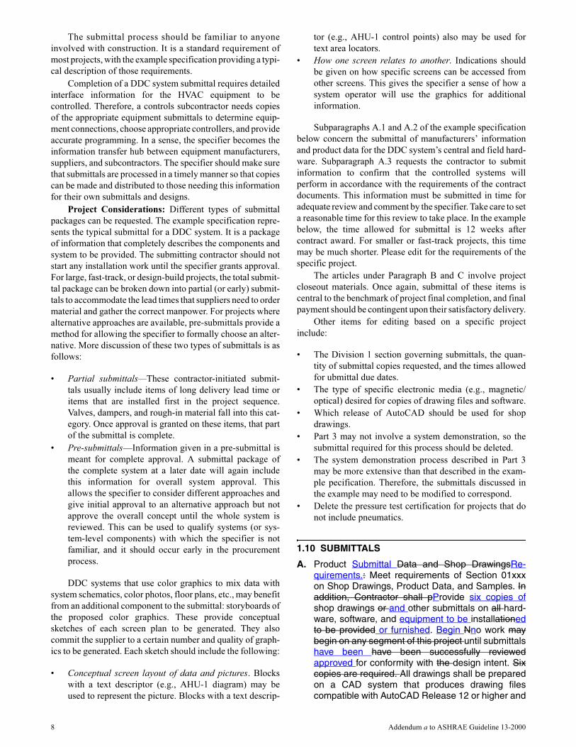
1.10 SUBMITTALS
A. Product Submittal Data and Shop DrawingsRe-quirements.: Meet requirements of Section 01xxxon Shop Drawings, Product Data, and Samples. Inaddition, Contractor shall pProvide six copies ofshop drawings or and other submittals on all hard-ware, software, and equipment to be installationedto be provided or furnished. Begin Nno work maybegin on any segment of this project until submittalshave been have been successfully reviewedapproved for conformity with the design intent. Sixcopies are required. All drawings shall be preparedon a CAD system that produces drawing filescompatible with AutoCAD Release 12 or higher and
8 Addendum a to ASHRAE Guideline 13-2000

be provided on magnetic/optical disk and as full-sizemylar drawings. When manufacturer’s cutsheetsapply to a product series rather than a specific prod-uct, clearly indicate the applicable data specificallyapplicable to the project shall bey highlighteding orclearly indicated by other means. Each submittedpiece of literature and drawings shall Cclearly refer-ence the covered specification and/or drawing oneach submittalthat the submittal is to cover. Generalcatalogs shall not be accepted as cut sheets to fulfillsubmittal requirements. Select and show submittalquantities appropriate to scope of work. ProvideSsubmittals shall be provided within 12 weeks ofcontract award on the following:. Submittals shallinclude:1. Direct Digital Control System Hardware:
a. A cComplete bill of materials of equipmentto be used indicating quantity, manufac-turer, model number, and other relevanttechnical data of equipment to be used.
b. Manufacturer’s description and technicaldata, such as performance curves, productspecification sheets, and installation and /maintenance instructions for the itemslisted below and for other relevant items notlisted below:1. Direct dDigital cControllers (controller
panels)2. Transducers and /Ttransmitters3. Sensors (including accuracy data)4. Actuators5. Valves6. Relays/ and Sswitches7. Control Ppanels8. Power sSupplyies9. Batteries10. Operator Iinterface Eequipment11. Wiring
c. Wiring diagrams and layouts for eachcontrol panel. S. Show all terminationnumbers.
d. Schematic diagrams for all field sensorsand controllers. Provide fFloor plan sche-matic diagrams indicating of all field sensorlocations and controller hardware locations.
2. Central System Hardware and Software:a. A cComplete bill of material of equipment
used, indicating quantity, manufacturer,model number, and other relevant technicaldata of equipment used.
b. Manufacturer’s description and technicaldata, such as product specifications sheetsand installation and /maintenance instruc-tions for the items listed below and for otherrelevant items furnished under this contractnot listed below:1. Central Processing Unit (CPU)2. Monitors3. Keyboards45. Power sSupply56. Battery Bbackup
67. Interface eEquipment bBetween CPUand cControl pPanels
78. Operating System sSoftware89. Operator Iinterface sSoftware910.Color Graphic graphic sSoftware101.Third-pParty sSoftware
c. Schematic diagrams forof all control,communication, and power wiring. Providea schematic drawing of the for centralsystem installation. Label all cables andports with computer manufacturers’ modelnumbers and functions. Show all interfacewiring to the control system.
d. Rriser diagrams of wiring between centralcontrol unit and all control panels.
de. A lList of the color graphics screens to beprovided. For each screen, pProvide aconceptual layout of pictures and data foreach graphic, and showing or explainingwhich other screens graphics can bedirectly accessed.
3. Controlled Systems:a. A sSchematic diagram of each controlled
system. The schematics shall have allLabelcontrol points labeled with point namesshown or listed. The schematics shallgGraphically show the locations of allcontrol elements in the system.
b. A sSchematic wiring diagram for of eachcontrolled system. Each schematic shallhave all elements labeledLabel controlelements and terminals. Where a controlelement is the same as that also shown onthe control system schematic, use it shall belabeled with the same name. All terminalsshall be labeled.
c. An iInstrumentation list for each controlledsystem. List Eeach control system elementof the controlled system shall be listed in atable format. The table shall sShow elementname, type of device, manufacturer, modelnumber, and product data sheet number.
d. A mMounting, wiring, and routing plan-viewdrawing . The drawing shall be done in ¼ in.scale. The design shall tTake into accountHVAC, electrical, and other systems’ designand elevation requirements. The drawingshall sShow the specific locations of allconcrete pads and bases and any specialwall bracing for panels to accommodate thiswork.
e. A cComplete description of the controlsystem operation of the control system,including sequences of operation. Thedescription shall iInclude and reference aschematic diagram of the controlledsystem.
f. A pPoint list for each system controllerincluding both inputs and outputs (I/O),point numbers, the controlled device asso-ciated with the each I/O point, and the loca-
Addendum a to ASHRAE Guideline 13-2000 9

tion of the I/O device. Indicate alarmedSoftware flag points, and trended alarmpoints, etc.
4. Quantities of items submitted shall be reviewedbut are the responsibility of the Contractor.
54. A dDescription of the proposed process, alongwith all report formats, and checklists to be usedin Part 3: “Control System Demonstration andAcceptance.”
65. A BACnet Protocol Implementation Conform-ance Statement (PICS) for each submitted typeof controller and operator interface included inthe submittal.
B. Schedules:1. Within one month of contract award, provide a
sSchedule of the work provided within onemonth of contract award indicating the following:a. Intended sequence of work items.b. Start dates of individual each work items.c. Duration of individual each work items.d. Planned delivery dates for major ordered
material and equipment and expected leadtimes.
e. Milestones indicating possible restraints onwork by other trades or situations.
2. Provide mMonthly written status reports indicat-ing work completed and, revisions to expecteddelivery dates, etc. An . Include updated projectschedule of work. shall be included.
C. Project Record Documents: Upon completion ofinstallation, sSubmit three copies of record (as-built)documents upon completion of installation . Thedocuments shall be submitted for approval prior tofinal completion. Submittal shall consist of: and shallinclude:1. Project Record Drawings. These shall be as-
built versions of the submittal shop drawings.One set of magnetic media including CAD,.DWG, or .DXF drawing files also shall beprovided.
2. Testing and Commissioning Reports andChecklists. Completed versions of all reports,and checklists, and along with all trend logs,used to meet the requirements of Part 3:“Control System Demonstration and Accep-tance.”
3. Certification of the pressure test required in Part3: “Control Air Tubing.”
4. Operation and Maintenance (O & M) Manual. . a. This shall include aAs-built versions of the
submittal product data.. In addition to theinformation required for submittals, the O &M manual shall include:
b. Names, addresses, and 24-hour telephonenumbers of installing contractors andservice representatives for installing equip-ment and the control systems and servicerepresentatives of each.
c. Operator’s Mmanual with procedures foroperating the control systems:, includinglogging on/ and off, handling alarms,
producing point reports, trending data,overriding computer control, and changingsetpoints and other variables.
d. One set of Programming Manualmanual orset of manuals with a description of theprogramming language and(includingsyntax), of statements descriptions for(including algorithms and calculationsused), of point database creation and modi-fication, of program creation and modifica-tion, and of editor use of the editor.
e. Engineering, Iinstallation, and Mmainte-nance Mmanual or set of manuals(s) thatexplains how to design and install newpoints, panels, and other hardware; how toperform preventive maintenance and cali-bration procedures; how to debug hardwareproblems; and how to repair or replacehardware.
f. A listing and dDocumentation of all customsoftware programs created using thecustom programming language, includingthe setpoints, tuning parameters, andobject database. One set of magnetic/opti-cal media containing files of the softwareand database also shall be provided.
g. Graphic files, programs, and databaseonOne set of magnetic or/ optical media.containing files of all color graphic screenscreated for the project.
h. A lList of recommended spare parts withpart numbers and suppliers.
i. Complete original original-issue documen-tation, installation, and maintenance infor-mation for furnished all third-party hardwareprovided, including computer equipmentand sensors.
j. Complete original original-issue diskettescopies of for all furnished softwareprovided, including operating systems,custom programming language, operatorworkstation software, and graphics soft-ware.
k. Licenses, guarantees, and warranty docu-ments for all equipment and systems.
l. Recommended preventive maintenanceprocedures for all system components,including a schedule of tasks such asinspection, cleaning, and calibration, etc.),;time between tasks;, and task descriptions.
D. Training Materialsnuals:. The contractor shall pPro-vide a course outline and training manuals for alleach training classes at least six weeks before priorto the first class. The eEngineer may will modify anyor all of the training course outlines and trainingmanualsterials if necessary to meet Owner’s theneeds of the owner. Engineer will Rreview andapprove course outlines and manualsal by the engi-neer shall be completed at least three weeks beforeprior to the first class.
10 Addendum a to ASHRAE Guideline 13-2000
7.11 Warranty
The warranty is usually a written guarantee of the integ-
rity of a product and/or service and the good faith of the manu-
facturer and/or installer given to the purchaser. It generally
specifies that the manufacturer and/or installer will, for a
period of time, be responsible for the repair or replacement of
defective parts—and will sometimes also provide periodic
servicing.
When preparing the warranty section for your project, the
following should be included and/or referenced in describing
the terms and conditions.
7.11.1 The General Conditions of the Specification
The general conditions define the warranty terms and
conditions for the entire project and should be referenced in
any warranty conditions listed in the controls specification.
7.11.2 The Guarantee
A guarantee that the temperature control system will be
“free from defects in workmanship and material.”
7.11.3 Warranty Period
The warranty period will vary with the type of project and
the owner’s requirements. A typical warranty period is one
year after system acceptance, although some owners may
desire up to five years. After the first year of acceptance, each
additional year may increase the cost of the project. It is gener-
ally observed that malfunctions and problems in electronic
equipment occur in the first year after installation. Thus, the
economic value of extending the warranty may not be justi-
fied. However, an owner may have other financial consider-
ations that justify an extended warranty.
7.11.4 Commencement of the Warranty
The DDC system warranty begins upon acceptance of the
system. The system can be accepted through one of three
common methods:
• The owner uses the system before the completion of the
project, thereby receiving beneficial use from the sys-
tem. This can constitute acceptance.
• The system can be accepted after the completion of each
phase of a multi-phase project.
• Acceptance occurs after an agreed-upon completion of a
demonstration or acceptance test of the system. An
“acceptance test” could include an endurance test, com-
missioning, and/or some other means of testing the per-
formance of the system.
After any of the above methods of acceptance, written
documentation is initiated by the manufacturer and/or
installer, placing the system and its components into warranty.
The document should stipulate the start date and duration of
the warranty period, as well as any additional services and/or
support provided to the purchaser that may exceed the terms
and conditions of the project. The warranty document may
include warranty registration cards covering various pieces of
hardware (to be completed and returned to the manufacturer
and/or installer) and any software licensing agreements
required by the manufacturer and/or installer. In addition, the
warranty may include a recommended spare parts list for the
owner.
7.11.5 Notification of Failure and/or Defects
The owner should contact the (prime) contractor during
the contract warranty period. If the control system warranty
exceeds the contract’s warranty, calls made after the contract’s
warranty expires should be made to the extended warranty
provider.
7.11.6 Response Time to Correct Failures and/or
Defects
Response time to a warranty call shall indicate the time
required to reach the job site following a call from the owner
to the contractor. A typical response time to a job site is 24
hours during normal business hours, with exceptions being
one hour, twenty-four hours a day, seven days a week, for crit-
ically operated facilities. Different response times could be
established for business hours, after hours, weekends, holi-
days, etc. To avoid any confusion, establish one acceptable
response time within a specific time frame.
7.11.7 Cost
To avoid additional cost to the owner, state that a warranty
response and the repair or replacement of a defective or failed
component should be made at no charge to the owner.
7.11.8 Software/Firmware Updates
To ensure that the owner will have the most current oper-
ating system provided by the manufacturer, it should be stated
in the specification that the manufacturer/installer shall
provide and install, at no charge to the owner, the latest firm-
ware and software applicable for this project before the expi-
ration of the warranty period. Including this statement may
increase the cost of a project.
7.11.9 Periodic Preventive Maintenance Service
Depending upon the owner’s needs and requirements for
the project, regular preventive maintenance of the system may
be necessary during the warranty period to ensure the proper
operation of the system. If regular maintenance is required, it
should be stated in the specification that during the warranty
period, the contractor shall provide normal maintenance
service as recommended by the manufacturer. Maintenance
shall include, but not be limited to, control components/instru-
ments, accessories, hardware, and software. The addition of
preventive maintenance will increase the cost of a project.
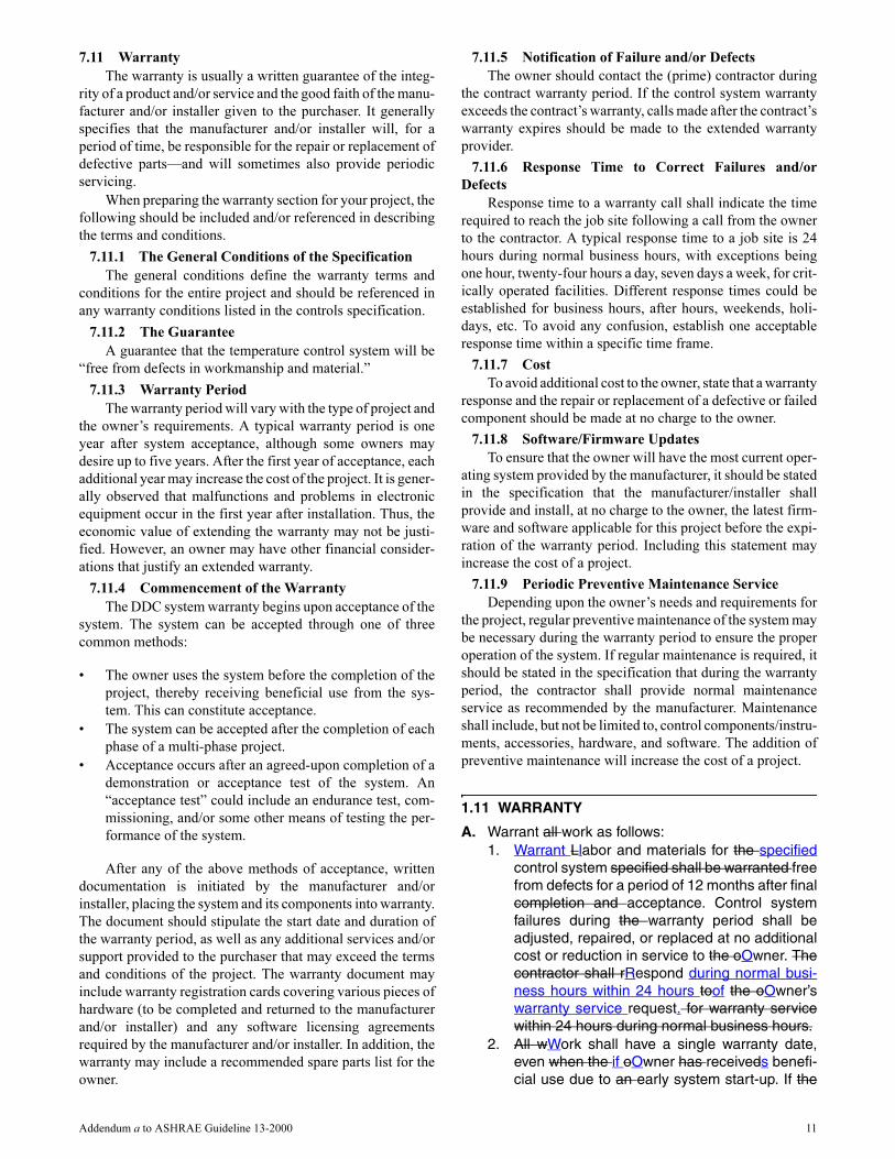
1.11 WARRANTY
A. Warrant all work as follows:1. Warrant Llabor and materials for the specified
control system specified shall be warranted freefrom defects for a period of 12 months after finalcompletion and acceptance. Control systemfailures during the warranty period shall beadjusted, repaired, or replaced at no additionalcost or reduction in service to the oOwner. Thecontractor shall rRespond during normal busi-ness hours within 24 hours toof the oOwner’swarranty service request. for warranty servicewithin 24 hours during normal business hours.
2. All wWork shall have a single warranty date,even when the if oOwner has receiveds benefi-cial use due to an early system start-up. If the
Addendum a to ASHRAE Guideline 13-2000 11
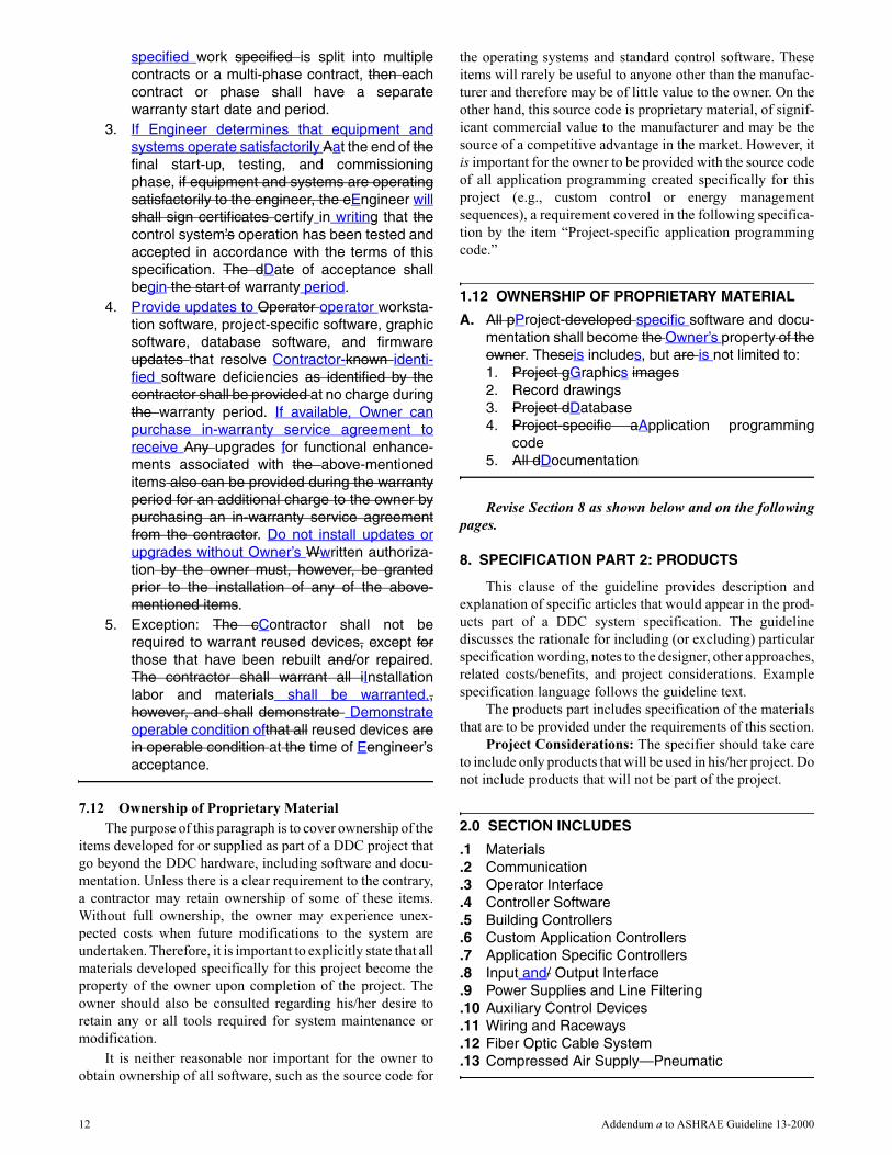
specified work specified is split into multiplecontracts or a multi-phase contract, then eachcontract or phase shall have a separatewarranty start date and period.
3. If Engineer determines that equipment andsystems operate satisfactorily Aat the end of thefinal start-up, testing, and commissioningphase, if equipment and systems are operatingsatisfactorily to the engineer, the eEngineer willshall sign certificates certify in writing that thecontrol system’s operation has been tested andaccepted in accordance with the terms of thisspecification. The dDate of acceptance shallbegin the start of warranty period.
4. Provide updates to Operator operator worksta-tion software, project-specific software, graphicsoftware, database software, and firmwareupdates that resolve Contractor-known identi-fied software deficiencies as identified by thecontractor shall be provided at no charge duringthe warranty period. If available, Owner canpurchase in-warranty service agreement toreceive Any upgrades for functional enhance-ments associated with the above-mentioneditems also can be provided during the warrantyperiod for an additional charge to the owner bypurchasing an in-warranty service agreementfrom the contractor. Do not install updates orupgrades without Owner’s Wwritten authoriza-tion by the owner must, however, be grantedprior to the installation of any of the above-mentioned items.
5. Exception: The cContractor shall not berequired to warrant reused devices, except forthose that have been rebuilt and/or repaired.The contractor shall warrant all iInstallationlabor and materials shall be warranted.,however, and shall demonstrate Demonstrateoperable condition ofthat all reused devices arein operable condition at the time of Eengineer’sacceptance.
7.12 Ownership of Proprietary Material
The purpose of this paragraph is to cover ownership of the
items developed for or supplied as part of a DDC project that
go beyond the DDC hardware, including software and docu-
mentation. Unless there is a clear requirement to the contrary,
a contractor may retain ownership of some of these items.
Without full ownership, the owner may experience unex-
pected costs when future modifications to the system are
undertaken. Therefore, it is important to explicitly state that all
materials developed specifically for this project become the
property of the owner upon completion of the project. The
owner should also be consulted regarding his/her desire to
retain any or all tools required for system maintenance or
modification.
It is neither reasonable nor important for the owner to
obtain ownership of all software, such as the source code for
the operating systems and standard control software. These
items will rarely be useful to anyone other than the manufac-
turer and therefore may be of little value to the owner. On the
other hand, this source code is proprietary material, of signif-
icant commercial value to the manufacturer and may be the
source of a competitive advantage in the market. However, it
is important for the owner to be provided with the source code
of all application programming created specifically for this
project (e.g., custom control or energy management
sequences), a requirement covered in the following specifica-
tion by the item “Project-specific application programming
code.”
1.12 OWNERSHIP OF PROPRIETARY MATERIAL
A. All pProject-developed specific software and docu-mentation shall become the Owner’s property of theowner. Theseis includes, but are is not limited to:1. Project gGraphics images2. Record drawings3. Project dDatabase4. Project-specific aApplication programming
code5. All dDocumentation
Revise Section 8 as shown below and on the following
pages.
8. SPECIFICATION PART 2: PRODUCTS
This clause of the guideline provides description and
explanation of specific articles that would appear in the prod-
ucts part of a DDC system specification. The guideline
discusses the rationale for including (or excluding) particular
specification wording, notes to the designer, other approaches,
related costs/benefits, and project considerations. Example
specification language follows the guideline text.
The products part includes specification of the materials
that are to be provided under the requirements of this section.
Project Considerations: The specifier should take care
to include only products that will be used in his/her project. Do
not include products that will not be part of the project.
2.0 SECTION INCLUDES
.1 Materials
.2 Communication
.3 Operator Interface
.4 Controller Software
.5 Building Controllers
.6 Custom Application Controllers
.7 Application Specific Controllers
.8 Input and/ Output Interface
.9 Power Supplies and Line Filtering
.10 Auxiliary Control Devices
.11 Wiring and Raceways
.12 Fiber Optic Cable System
.13 Compressed Air Supply—Pneumatic
12 Addendum a to ASHRAE Guideline 13-2000

8.1 Materials
In general, it is important to specify that the products and
materials that are provided should be new, part of the manu-
facturer’s current product line, and that they will be supported
for at least five years.
Project Considerations: The requirement for the use of
new materials and equipment in this article should be
reviewed and coordinated with the requirements of Part 3,
especially the article on Existing Equipment” that is reused in
retrofit or renovation projects. This example also requires that
the systems installed use technology that has been in use for at
least two years. The technology used in this industry changes
rapidly, so it may be worthwhile to consider reducing this time
period. The specifier should strive to review the technology
offerings available before the specification is out for bid to
avoid the embarrassment of specifying systems or equipment
that may no longer be available.
2.1 MATERIALS
A. All products used in this project installation shall benew and currently under manufacture and shall havebeen applied in similar installations for a minimum oftwo years. Do not use This this installation shall notbe used as a product test site for any new productsunless explicitly approved in writing by the Owner oroOwner's representative in writing. Spare partsshall be available for at least five years after comple-tion of this contract.
8.2 Communication
8.2.1 Network Arrangement
The arrangement of the controllers and how they are
linked together in a network is called system “architecture” or
network “topology.” Selection of the physical media (wires)
and data link layers (called communication “buses”) is very
much an individual choice at each installation.
There are generally three types of communication buses
related to building control systems:
a. Communication between workstations.
b. Communication between controllers (and the worksta-
tion-to-controller communication).
c. Communication between secondary level controllers
(such as terminal unit controllers or interfaces to third-
party equipment such as switchgears, packaged HVAC
equipment, etc.) that provide communication to the
workstation, routed through a primary controller (or
other interface).
Note that while the different functions of these three buses
reside within all DDC systems, some systems accomplish
these functions with two or even one bus.
Many DDC systems use commercially available local
area network (LAN) technologies (e.g., Ethernet) for system
communication. These LAN technologies are also popular for
use in office or factory automation communication, some-
times referred to as an “intranet.” Therefore, the designer is
confronted with the choice of installing a dedicated LAN for
the DDC system or sharing the LAN with other systems.
Unfortunately, a definitive analysis of whether a shared LAN
will have sufficient capacity for all systems is not an easy task.
It requires an intimate knowledge of how each one of the
systems uses the LAN, both in general and for the specific
installation involved. Therefore, a final decision is best made
through consultation with the manufacturers of the DDC
equipment and the other equipment involved. Given that this
type of consultation is not always possible, the safest choice
for a DDC system is to use a dedicated LAN.
8.2.2 Workstation Communication
This type of communication is high speed and data rich.
While communication between workstations may not be
frequent, it usually involves large blocks of data, particularly
file exchanges, that must occur at high speed. This bus also
may be part of the facility-wide intranet, where other office or
factory automation traffic occurs. The communication
between controllers and workstations also can occur on this
bus—alarm reporting and acknowledgement, graphic display
updates, and so on. Once again, consultation with the owner
and information system managers is critical if this communi-
cation is to occur on a shared intranet.
8.2.3 Controller Communication
This bus can have the greatest effect on overall system
throughput. All global objects will communicate over this bus,
as well as alarms. Additionally, operator-entered commands
and requests for information are transmitted over this bus.
This bus must be responsive enough to guarantee timely alarm
reporting while still processing regular activities such as
reports and global objects. Response time in seconds is still the
best measure.
8.2.4 Secondary Bus Communication
Speed for this bus must be evaluated on an application
basis. The most common use for this bus is for terminal unit
controllers. As space temperature has a large capacity and
does not change rapidly, bus response can be relatively slow
in many cases. It typically does not create large errors if the
reported information is 30 or even 60 seconds old.
A building operator can work with these delays without
frustration; however, some method must be provided whereby
commands can be issued to (and information retrieved from)
a specific controller without having to wait for the entire poll-
ing cycle. Otherwise, delays of several seconds will be
extremely frustrating.
In other cases, such as when the bus is used to monitor
switchgear or packaged computer room control systems, fast
throughput is necessary for alarm reporting.
8.2.5 System Architecture
The system architecture, topology, or arrangement of
devices on the networks that makes up a building automation
system is a function of many decisions made by the engineer,
system supplier, and owner. No one topology is universally the
best for all system applications.
When specifying a system, it may be necessary to deter-
mine the network architecture required to ensure that the prod-
ucts of several vendors on a project will be able to interoperate.
This may require the use of some more definitive prescriptive
language. The extent to which a specification can be perfor-
Addendum a to ASHRAE Guideline 13-2000 13

mance-based or prescriptive depends on the nature of the
project. Examples of this include:
1. New installation, entire system provided by one vendor: A
pure performance-based specification should be used. This
will allow the most economical solution to be applied.
Future additions to the project will follow the same network
communications options as provided in the first phase.
2. New installation, system provide by various suppliers: For
example, this might be a system where the HVAC controls
are bid and provided under section 15950, but the chillers
that communicate with the system are bid in another
section, and the fire alarm that also communicates with the
system is bid in a third section. Make the specification
prescriptive in describing the networking architecture in
each of these sections.
3. Expansion of an existing installation: Make the specifica-
tion highly prescriptive because the new equipment must
connect to the existing systems.
The example specification illustrates a system where
various suppliers may provide various systems. It uses a two-
tiered topology, where the operator workstations and building
controllers operate as peers on a BACnet Ethernet LAN.
Application specific controllers (shown as “ASC” in Figure 6)
and custom application controllers (CAC) operate as peers on
a number of subnetworks that each use a BACnet MS/TP
LAN. The building controllers act as routers to connect the
MS/TP subnetworks to the higher speed Ethernet LAN, form-
ing a BACnet internetwork.
It is easy to imagine many variations of this example.
Each installation invariably will have unique characteristics
about its network arrangement. The contract documents must
clearly indicate this topology so that the proposals submitted
will be evaluated fairly against each other. It is also especially
important to have defined the topology and character of the
network if control devices specified elsewhere, such as boiler
controls and packaged chiller controllers, are to be linked to
the network. If the choice of LAN types is left to the supplier
of the DDC system, then coordinating the connection of
control devices specified elsewhere becomes problematic.
The example specification also cites the use of peer-to-
peer communication, where each device on a segment of the
network has the ability to communicate with any of its peers
on an as-needed, as-required basis. This is in contrast to a poll-
and-response communication, in which devices on the
network segment cannot communicate unless polled by a
“master” device.
8.2.6 Communication Performance
DDC system communication is tied most directly to the
“Communication” article of the example specification but
also deals with other areas of the specification, most notably
the “System Performance” article.
Figure 6 System architecture.
14 Addendum a to ASHRAE Guideline 13-2000

8.2.7 Communication Protocols
8.2.7.1 Interoperability
It is important to note that the goal of interoperability
between different manufacturers’ control system components
is the reliable and timely function of reading and writing data
between the devices. This functionality is required at all the
levels of the network where different manufacturers’ devices
must interoperate.
Other functions, such as the exchange and manipulation
of alarms, schedules, and trends, also may need to occur in the
multi-vendor environment. Invariably, however, this commu-
nication happens at the operator workstation and building
controller levels.
There is a broad range of functions for use in DDC
systems. In an interoperable system, several of these functions
may be required.
8.2.7.1.1 Data Exchange
The exchange of data between two devices (e.g., PC
workstations, building controllers, custom application
controllers, or application specific controllers) is the most
basic of interoperable functions. This function allows for both
the viewing (or reading) of data as well as making changes (or
writing) to these data. This can be accomplished by a number
of methods. The most basic of these is a pair of services called
“Read Property” and “Write Property.” In some open proto-
cols, data are modeled as “objects.” Each of these objects has
a series of “properties” defined. For example:
An ABC protocol-compatible building controller has a
temperature sensor that measures the outdoor air temperature.
This is modeled as an ABC protocol analog input object. This
object, as defined in the ABC protocol, has several standard
properties including “Name” and “Present Value.” To view the
outdoor air temperature, one could use an ABC protocol-
compatible PC workstation and ask for (read) the present
value of the analog input named “Outdoor Air Temperature.”
In the same manner, one can change set points (write) to
the present value property of analog and binary output objects.
These basic functions can be used to share set points between
controllers, provide graphics data on a PC workstation,
command the lights to come on, or sample data in a trend.
In fact, entire interoperable systems can be built just by
using these basic functions. Similar functions are also
provided by many interoperable protocols including BACnet,
LonMark, and ModBus.
8.2.7.1.2 Advanced Interoperable Functions
While the data exchange function is able to achieve a wide
variety of functions, there are more efficient ways to accom-
plish a number of system functions. These are required for
large installations and for use in remote operations of multiple
buildings.
(1) Alarms and Events
This function allows for the exchange of alarm informa-
tion in an interoperable system. A controller that has deter-
mined that an alarm has occurred is able to send an alarm
message to a predetermined location. For example:
A building controller is connected to a network of appli-
cation specific controllers. On one of these controllers, the
space temperature becomes too high. In the building control-
ler, a program periodically compares the space temperature to
a user-entered alarm limit. When the temperature exceeds that
limit, the building controller generates an alarm and sends it to
the PC workstation. At that workstation, an operator reads the
alarm and acknowledges it.
The protocol defines how the alarms are generated, how
they are sent, and what they should contain. This function is
typically done between a building controller and a PC work-
station but could also occur in other controllers on the intranet.
This function also might be used to trigger a control action or
record an operator override.
(2) Schedules
This set of functions allows for the editing and creation of
schedules on a PC workstation that will be executed in a
controller. For example:
The operator wants to change the fan’s stop time in the
auditorium from 6:00 p.m. to 9:00 p.m. Using the scheduling
function, the operator is able to load the schedule from the
controller, select the stop time, and change that parameter.
This function will typically occur between a PC worksta-
tion and a building controller but also could occur on other
controllers on the intranetwork.
(3) Trends
The ability to sample, store, and read trends is a valuable
function. Trending is a valuable tool for collecting data on
system performance and energy usage. While trends are typi-
cally stored on a PC workstation, there are a number of reasons
to initially store them in a controller. This will minimize
network traffic and also will allow for sampling of data if a PC
is not continually connected to the controller.
(4) Network Management
The final interoperable function is the ability to manage
the devices on the network. This includes tasks such as moni-
toring for a loss of communication and coordinating the time
settings on the clocks in each controller.
8.2.7.2 Network Communications
While the example specification uses the BACnet stan-
dard to help define communication within the DDC network,
the use of a communication protocol is a choice made by the
specifier. The specifier may find it most advantageous—either
because of cost constraints, standard purchasing agreements,
or other circumstances—to specify that the network commu-
nication can be conducted on a proprietary network. Or if there
is no need for devices specified elsewhere to communicate on
this network, it may be reasonable to leave the network type
and media type completely to the discretion of the contractor.
A number of other open protocols exist in the market-
place. If the specifier wishes to use one of these protocols, it
is strongly recommended that the specifier make extensive use
of the resources available from the promoters of that protocol
in the writing of their project-specific application. The
ASHRAE BACnet protocol has been used as the basis for the
example specification.
Addendum a to ASHRAE Guideline 13-2000 15
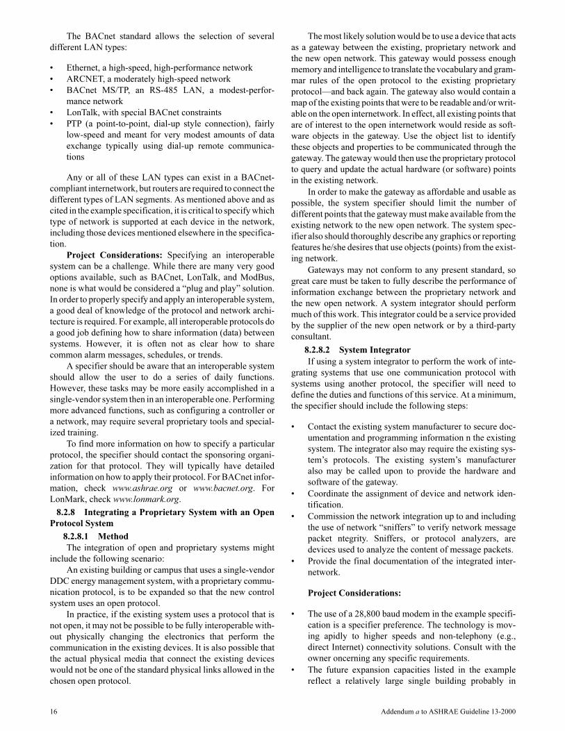
The BACnet standard allows the selection of several
different LAN types:
• Ethernet, a high-speed, high-performance network
• ARCNET, a moderately high-speed network
• BACnet MS/TP, an RS-485 LAN, a modest-perfor-
mance network
• LonTalk, with special BACnet constraints
• PTP (a point-to-point, dial-up style connection), fairly
low-speed and meant for very modest amounts of data
exchange typically using dial-up remote communica-
tions
Any or all of these LAN types can exist in a BACnet-
compliant internetwork, but routers are required to connect the
different types of LAN segments. As mentioned above and as
cited in the example specification, it is critical to specify which
type of network is supported at each device in the network,
including those devices mentioned elsewhere in the specifica-
tion.
Project Considerations: Specifying an interoperable
system can be a challenge. While there are many very good
options available, such as BACnet, LonTalk, and ModBus,
none is what would be considered a “plug and play” solution.
In order to properly specify and apply an interoperable system,
a good deal of knowledge of the protocol and network archi-
tecture is required. For example, all interoperable protocols do
a good job defining how to share information (data) between
systems. However, it is often not as clear how to share
common alarm messages, schedules, or trends.
A specifier should be aware that an interoperable system
should allow the user to do a series of daily functions.
However, these tasks may be more easily accomplished in a
single-vendor system then in an interoperable one. Performing
more advanced functions, such as configuring a controller or
a network, may require several proprietary tools and special-
ized training.
To find more information on how to specify a particular
protocol, the specifier should contact the sponsoring organi-
zation for that protocol. They will typically have detailed
information on how to apply their protocol. For BACnet infor-
mation, check www.ashrae.org or www.bacnet.org. For
LonMark, check www.lonmark.org.
8.2.8 Integrating a Proprietary System with an Open
Protocol System
8.2.8.1 Method
The integration of open and proprietary systems might
include the following scenario:
An existing building or campus that uses a single-vendor
DDC energy management system, with a proprietary commu-
nication protocol, is to be expanded so that the new control
system uses an open protocol.
In practice, if the existing system uses a protocol that is
not open, it may not be possible to be fully interoperable with-
out physically changing the electronics that perform the
communication in the existing devices. It is also possible that
the actual physical media that connect the existing devices
would not be one of the standard physical links allowed in the
chosen open protocol.
The most likely solution would be to use a device that acts
as a gateway between the existing, proprietary network and
the new open network. This gateway would possess enough
memory and intelligence to translate the vocabulary and gram-
mar rules of the open protocol to the existing proprietary
protocol—and back again. The gateway also would contain a
map of the existing points that were to be readable and/or writ-
able on the open internetwork. In effect, all existing points that
are of interest to the open internetwork would reside as soft-
ware objects in the gateway. Use the object list to identify
these objects and properties to be communicated through the
gateway. The gateway would then use the proprietary protocol
to query and update the actual hardware (or software) points
in the existing network.
In order to make the gateway as affordable and usable as
possible, the system specifier should limit the number of
different points that the gateway must make available from the
existing network to the new open network. The system spec-
ifier also should thoroughly describe any graphics or reporting
features he/she desires that use objects (points) from the exist-
ing network.
Gateways may not conform to any present standard, so
great care must be taken to fully describe the performance of
information exchange between the proprietary network and
the new open network. A system integrator should perform
much of this work. This integrator could be a service provided
by the supplier of the new open network or by a third-party
consultant.
8.2.8.2 System Integrator
If using a system integrator to perform the work of inte-
grating systems that use one communication protocol with
systems using another protocol, the specifier will need to
define the duties and functions of this service. At a minimum,
the specifier should include the following steps:
• Contact the existing system manufacturer to secure doc-
umentation and programming information n the existing
system. The integrator also may require the existing sys-
tem’s protocols. The existing system’s manufacturer
also may be called upon to provide the hardware and
software of the gateway.
• Coordinate the assignment of device and network iden-
tification.
• Commission the network integration up to and including
the use of network “sniffers” to verify network message
packet ntegrity. Sniffers, or protocol analyzers, are
devices used to analyze the content of message packets.
• Provide the final documentation of the integrated inter-
network.
Project Considerations:
• The use of a 28,800 baud modem in the example specifi-
cation is a specifier preference. The technology is mov-
ing apidly to higher speeds and non-telephony (e.g.,
direct Internet) connectivity solutions. Consult with the
owner oncerning any specific requirements.
• The future expansion capacities listed in the example
reflect a relatively large single building probably in
16 Addendum a to ASHRAE Guideline 13-2000

excess of 100,000 m2 or 1 million ft2). Other projects
may require a smaller number of future connections r, in
the case of an extensive campus, many more. Care
should be taken in choosing this number since it could
have an ffect on the system cost.
• The example specification uses BACnet to specify its
communication requirements for interoperability. There
are many ther methods, both proprietary and open, such
as LonMark-compliant, CAB, and ModBus to accom-
plish these same requirements.
2.2 COMMUNICATION
A. All control products provided for this project shallcomprise a BACnet internetwork. Communicationinvolving control components (i.e., all types ofcontrollers and operator interfaces) shall conform toANSI/ASHRAE Standard 135-19952004, BACnet.
B. Each BACnet device shall operate on the BACnetData Link/Physical layer protocol specified for thatdevice as defined in this section.
C. The contractor shall provide all communicationmedia, connectors, repeaters, hubs, and routersnecessary for the internetwork.
D. All controllers shall have a communication port forconnections with the operator interfaces using theBACnet Data Link/Physical layer protocol.
E. A device on the internetwork shall be provided witha 28,800 baud modem that will allow for remoteoperator interface using the BACnet PTP Data Link/Physical layer protocol. Remote operator interfacevia this modem shall allow for communication withany and all controllers on this network as describedin Paragraph F below.
F. Communication services over the internetwork shallresult in operator interface and value passing that istransparent to the internetwork architecture asfollows:1. Connection of an operator interface device to
any one controller on the internetwork will allowthe operator to interface with all other controllersas if that interface were directly connected to theother controllers. Data, status information,reports, system software, custom programs,etc., for all controllers shall be available for view-ing and editing from any one controller on theinternetwork.
2. All database values (e.g., objects, softwarevariables, custom program variables) of any onecontroller shall be readable by any other control-ler on the internetwork. This value passing shallbe automatically performed by a controller whena reference to an object name not located in thatcontroller is entered into the controller’s data-base. An operator/installer shall not be requiredto set up any communication services toperform internetwork value passing.
G. All system devices with real-time clocks shall usethe BACnet Time Synchronization service. The
system shall also automatically synchronize allsystem clocks daily from an operator-designateddevice in the system via the internetwork. Thesystem shall automatically adjust for daylightsavings and standard time, if applicable.The timeclocks in all controllers shall be automaticallysynchronized daily via the internetwork. An operatorchange to the time clock in any controller shall beautomatically broadcast to all controllers on theinternetwork.
H. The internetwork shall have the following minimumcapacity for future expansion:1. Each building controller shall have routing
capacity for 50 controllers.2. The building controller network shall have
capacity for 50 building controllers.3. The system shall have an overall capacity for
12,500 building controller, custom applicationcontroller, and application specific controllerinput/output objects.
8.3 Operator Interface
The operator interface section of this clause describes
what the system operator will see when he/she interfaces with
the system. This discussion is tightly coupled with the control-
ler software section that follows.
8.3.1 Number of Operator Interface Devices Required
This simply sets the desired number of operator interface
devices (workstations) that will be provided. The location of
these devices should be clearly shown in the project plans. If
portable operator devices are specified, then designate the
quantities to be provided.
Project Considerations: The number of workstations is
very much an individual project-specific requirement. Many
projects only require one workstation, so the wording of this
article should be carefully prepared to reflect that. Remember
that in this example, the workstations and the building control-
lers are both connected to the same high-speed network. Other
system architectures are possible and will require different
specification descriptions here.
2.3 OPERATOR INTERFACE
A. Operator Interface. Furnish two PC-based worksta-tions shall reside on high-speed network with build-ing controllers as shown on the system drawings.Each of these workstations or each standardbrowser connected to server shall be able to accessall system information in the system. These work-stations shall reside on the same high-speednetwork as the building controllers.
8.3.2 Physical System Connection
On a small project, the operator interface device may be
connected directly to a panel or may be remotely located and
connected by dial-up phone modem. On a larger project,
where several operator interface devices are required, they
will typically be connected on a high-speed LAN.
Addendum a to ASHRAE Guideline 13-2000 17

Project Considerations: The example specification
requires an Ethernet LAN (ISO 8802-3). Exercise caution in
specifying connection via dial-up. Communication speed is
much slower over a dial-up connection.
B. Workstation and controllers shall communicateinformation access shall usinge the BACnet proto-col. Workstation and control network backbone shallCcommunicatione shall usinge the ISO 8802-3(Ethernet) Data Link/Physical layer protocol andBACnet/IP addressing as specified in ANSI/ASHRAE 135-2004, BACnet, Annex J.
8.3.3 System Hardware
For most projects, the operator interface will be a personal
computer (PC). This is an economical, commonly available
device that can be used for other functions by the owner,
including word-processing, maintenance management, and
other common functions. The specification for the personal
computer needs to be updated to reflect the current state of the
art. This typically changes once or twice a year. The elements
that are subject to change are the processor and speed, as well
as memory and hard drive capacity.
Accessories required with the PC also should be specified
in this section. This will typically include the printer and
modem for remote communication.
Project Considerations: Buildings that will have on-site
operations should include at least one PC workstation. Larger
facilities may have several PCs that are conveniently located
throughout the building. Consult with the owner to verify the
need and location of these workstations. Smaller buildings and
those that do not have on-site operators may not require an on-
site PC. For these projects, several options are available. The
most basic option is to use a simple LCD display. This typi-
cally consists of an LCD display panel and a keypad, which
allows operators to see objects’ status, view alarms, and
change set points and schedules. A second option is not to have
any local operator interface but to rely on remote communi-
cation and a portable operator’s terminal. This would require
the specification of a modem for the project and the use of a
new or existing remote PC workstation for monitoring and
control. Finally, since the technology curve for personal
computers is very steep, the speed, memory, and storage
capacity requirements require careful review each time a spec-
ification is written for a new project.
If this project justifies the need for interoperability with
other systems during future expansion, such as a campus
setting or large, complex building that undergoes frequent
expansion and renovation (hospitals and/or research laborato-
ries), include the BACnet paragraph.
C. Hardware. Each operator workstation and customprogramming workstation shall consist of the follow-ing:
1. Personal Computer. Furnish IBM compatiblePCs as shown. The CPU shall be a minimum ofan Intel Pentium and operate at a minimum of120 MHz. A minimum of 16 megabytes of RAM,
one 1.44 megabyte 3.5-inch diskette drive, andan 800-megabyte hard disk with a minimumaccess time of 12 milliseconds shall beprovided. A two-button mouse also will beprovided. Furnish all required serial, parallel,and network communication ports and allcables for proper system operation. The PCshall have a minimum of a 14-in. VGA monitor.
2. Modems. Furnish one auto-dial telephonemodem per workstation and associated cablesfor communication to remote buildings andworkstations. The modem shall transmit at aminimum of 28,800 baud and communicateover voice-grade telephone lines.
3. Printers. Each workstation shall have oneprinter with tractor feed and associated cables.Each printer shall be capable of a minimum 160characters per second operation and becompatible with standard parallel or serialcommunication. Supply one box of 2000 sheetsminimum of printer paper and two printerribbons or cartridges.
4. BACnet. The workstation shall use the Read(Initiate) and Write (Execute) Services asdefined in Clauses 15.5 and 15.8, respectively,of ANSI/ASHRAE Standard 135-19952004 tocommunicate with BACnet objects in the inter-network.
8.3.4 System Software
This section only details the software that runs on the PC
workstation. All of the other functions described under system
applications are edited and archived at the PC workstation but
are actually executed at the system controllers. Refer to Clause
8.4 of this document, “Controller Software.”
8.3.4.1 Operating System
The operating system for the PC workstation should be
multi-tasking and support the use of other current off-the-shelf
programs. This is one place where the specifier may want to
be prescriptive in stating the allowable operating systems that
will support the other programs the system operator may wish
to use. Be sure that the allowable manufacturers are able to
support the specified operating system.
D. System Software
1. Operating System. Furnish a concurrent multi-tasking operating system. The operatingsystem also shall support the use of othercommon software applications that operateunder DOS or Windows. Examples includeLotus 123, Microsoft Excel, WordPerfect, andParadoxMicrosoft Access. Acceptable operat-ing systems are Windows 952000, WindowsNTXP, Windows Server 2003, Linux, and UNIX,and OS/2.
18 Addendum a to ASHRAE Guideline 13-2000

POLICY STATEMENT DEFINING ASHRAE’S CONCERNFOR THE ENVIRONMENTAL IMPACT OF ITS ACTIVITIES
ASHRAE is concerned with the impact of its members’ activities on both the indoor and outdoor environment. ASHRAE’smembers will strive to minimize any possible deleterious effect on the indoor and outdoor environment of the systems andcomponents in their responsibility while maximizing the beneficial effects these systems provide, consistent with acceptedstandards and the practical state of the art.
ASHRAE’s short-range goal is to ensure that the systems and components within its scope do not impact the indoor andoutdoor environment to a greater extent than specified by the standards and guidelines as established by itself and otherresponsible bodies.
As an ongoing goal, ASHRAE will, through its Standards Committee and extensive technical committee structure,continue to generate up-to-date standards and guidelines where appropriate and adopt, recommend, and promote those newand revised standards developed by other responsible organizations.
Through its Handbook, appropriate chapters will contain up-to-date standards and design considerations as the material issystematically revised.
ASHRAE will take the lead with respect to dissemination of environmental information of its primary interest and will seekout and disseminate information from other responsible organizations that is pertinent, as guides to updating standards andguidelines.
The effects of the design and selection of equipment and systems will be considered within the scope of the system’sintended use and expected misuse. The disposal of hazardous materials, if any, will also be considered.
ASHRAE’s primary concern for environmental impact will be at the site where equipment within ASHRAE’s scopeoperates. However, energy source selection and the possible environmental impact due to the energy source and energytransportation will be considered where possible. Recommendations concerning energy source selection should be made byits members.