AS35 brochure 2012Aug:AS35Brochure · Tata HPS200 Tata & Dobel PVDF White lining enamel 200LG...
36
AS35 i n s u l a t e d r o o F & w a l l p a n e l s Manufacturers of Cladding Products for the Construction Industry October 2012 CI/SfB (4-) Nh2
Transcript of AS35 brochure 2012Aug:AS35Brochure · Tata HPS200 Tata & Dobel PVDF White lining enamel 200LG...

AS35
insulated rooF & wall panelsManufacturers of Cladding Products for the Construction Industry
October 2012
CI/SfB(4-) Nh2
AS35Insulated Roof & Wall panels
introduction
AS35 Insulated Roof & Wall panels
2
Index
Introduction
About Steadmans
Requirements
Technical description
Performance
Accessories
Design
Design detailsRoofsWallsRooflights
Sitework
Maintenance
Supply and delivery
Technical support
2
2
3
3 - 4
5 - 7
8
9 - 12
13 - 2425 - 29
30
31 - 33
34
34
35
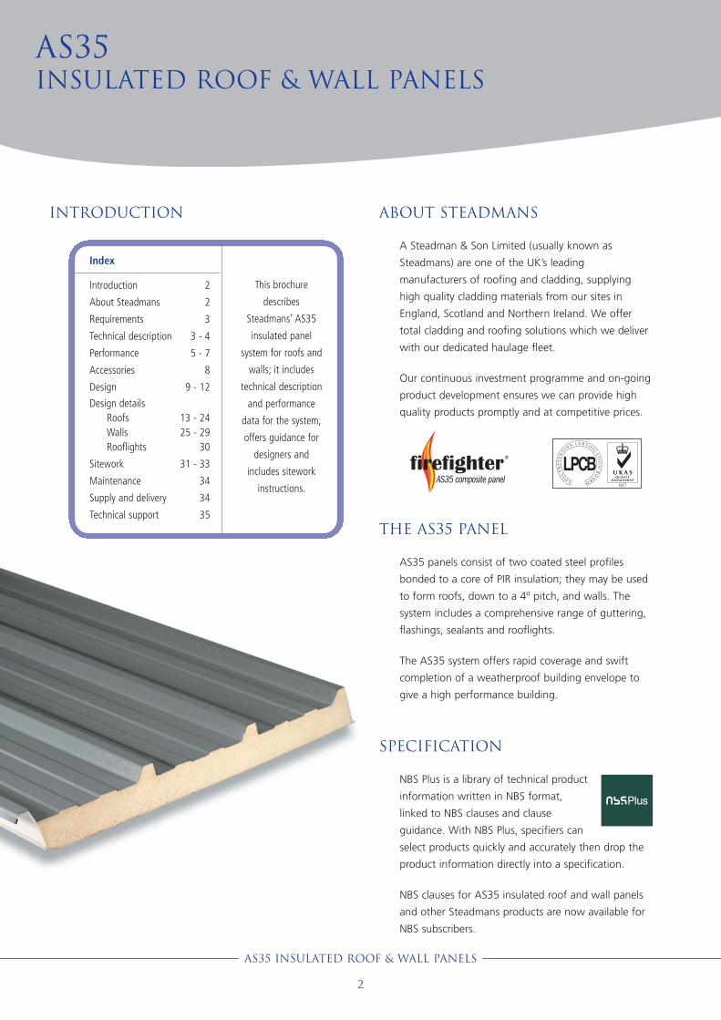
AS35 panels consist of two coated steel profiles
bonded to a core of PIR insulation; they may be used
to form roofs, down to a 4º pitch, and walls. The
system includes a comprehensive range of guttering,
flashings, sealants and rooflights.
The AS35 system offers rapid coverage and swift
completion of a weatherproof building envelope to
give a high performance building.
About Steadmans
A Steadman & Son Limited (usually known as
Steadmans) are one of the UK’s leading
manufacturers of roofing and cladding, supplying
high quality cladding materials from our sites in
England, Scotland and Northern Ireland. We offer
total cladding and roofing solutions which we deliver
with our dedicated haulage fleet.
Our continuous investment programme and on-going
product development ensures we can provide high
quality products promptly and at competitive prices.
This brochure
describes
Steadmans’ AS35
insulated panel
system for roofs and
walls; it includes
technical description
and performance
data for the system,
offers guidance for
designers and
includes sitework
instructions.
the as35 panel
NBS Plus is a library of technical product
information written in NBS format,
linked to NBS clauses and clause
guidance. With NBS Plus, specifiers can
select products quickly and accurately then drop the
product information directly into a specification.
NBS clauses for AS35 insulated roof and wall panels
and other Steadmans products are now available for
NBS subscribers.
specification
AS35 roof and wall panels are manufactured in a process
certified to ISO 9001:2008.
AS35 roof and wall panels have been tested by the
Loss Prevention Certification Board and comply with the
requirements of LPS 1181:2005. Part 1 Issue 1.1: Series of
Fire Growth Tests for LPCB Approval and Listing of
Construction Product Systems - Part 1: “Requirements
and Tests for Built-Up Cladding and Sandwich Panel
Systems for Use as the External Envelope of Buildings”.
Installation warrantySteadmans offer an independent audit-based warranty for
the AS35 insulated panel cladding system.
The QA+ warranty, from Auditing Workmanship &
Materials Ltd, provides pre-site and on-site quality
inspections and audits to ensure the high standards of
construction and finishing which will maximise service life
and reduce maintenance costs.
The QA+ warranty can be extended to a ten year
insurance backed warranty covering defects arising from
poor workmanship, defective materials and damage
resulting from design defects. Contact Steadmans for
more information about the warranties.
CompositionAS35 insulated panels consist of a core of
polyisocyanurate (PIR) insulation sandwiched between a
heavily profiled external weather sheet and an internal
shallow profiled liner. The PIR insulation bonds to the steel
sheets during the manufacturing process, together the
insulation and steel form strong, rigid panels with good
thermal performance.
On one side of the panel (the ‘female’ side) the weather
sheet extends beyond the insulation to permit lapping, on
the other side (the ‘male’ side) the exposed edge of the
insulation is sealed with factory applied anti-condensation
tape. Panels can be supplied with the insulation cut back
at one end to enable the formation of end laps on wide
span roofs.
Technical description
AS35 Insulated Roof & Wall panels
3
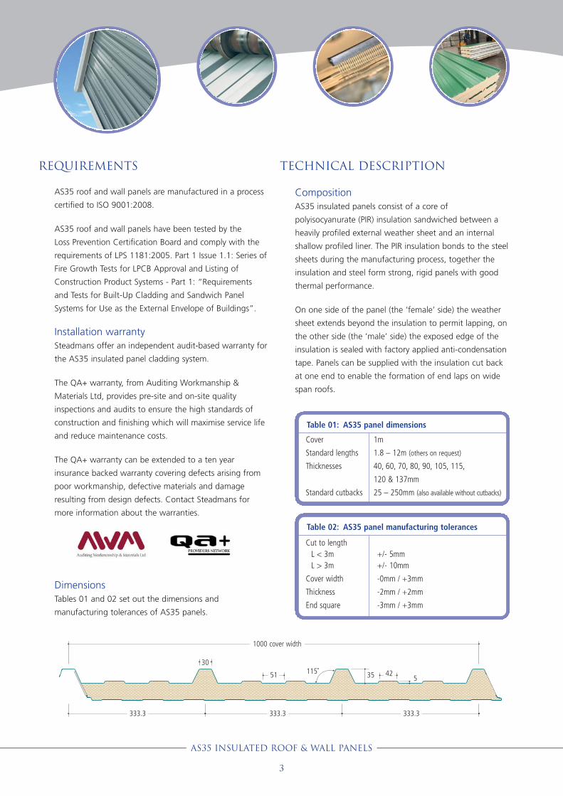
Table 01: AS35 panel dimensions
Cover
Standard lengths
Thicknesses
Standard cutbacks
1m
1.8 – 12m (others on request)
40, 60, 70, 80, 90, 105, 115,
120 & 137mm
25 – 250mm (also available without cutbacks)
Table 02: AS35 panel manufacturing tolerances
Cut to lengthL < 3mL > 3m
Cover width
Thickness
End square
+/- 5mm+/- 10mm
-0mm / +3mm
-2mm / +2mm
-3mm / +3mm
Requirements
DimensionsTables 01 and 02 set out the dimensions and
manufacturing tolerances of AS35 panels.
35 551
333.3 333.3333.3
42
1000 cover width
30115˚
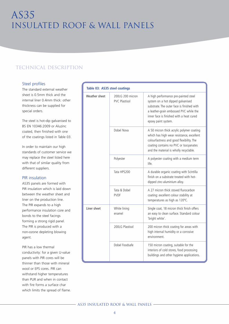
Steel profilesThe standard external weather
sheet is 0.5mm thick and the
internal liner 0.4mm thick: other
thickness can be supplied for
special orders.
The steel is hot-dip galvanised to
BS EN 10346:2009 or Aluzinc
coated, then finished with one
of the coatings listed in Table 03.
In order to maintain our high
standards of customer service we
may replace the steel listed here
with that of similar quality from
different suppliers.
PIR insulationAS35 panels are formed with
PIR insulation which is laid down
between the weather sheet and
liner on the production line.
The PIR expands to a high
performance insulation core and
bonds to the steel facings
forming a strong rigid panel.
The PIR is produced with a
non-ozone depleting blowing
agent.
PIR has a low thermal
conductivity: for a given U-value
panels with PIR cores will be
thinner than those with mineral
wool or EPS cores. PIR can
withstand higher temperatures
than PUR and when in contact
with fire forms a surface char
which limits the spread of flame.
AS35Insulated Roof & Wall panels
Technical description
AS35 Insulated Roof & Wall panels
4
Table 03: AS35 steel coatings
Weather sheet 200LG 200 micronPVC Plastisol
A high performance pre-painted steelsystem on a hot dipped galvanisedsubstrate. The outer face is finished witha leather-grain embossed PVC while theinner face is finished with a heat curedepoxy paint system.
Liner sheet
Dobel Nova
Polyester
Tata HPS200
Tata & DobelPVDF
White lining enamel
200LG Plastisol
Dobel Foodsafe
A 50 micron thick acrylic polymer coatingwhich has high wear resistance, excellentcolourfastness and good flexibility. Thecoating contains no PVC or Isocyanatesand the material is wholly recyclable.
A polyester coating with a medium termlife.
A durable organic coating with Scintillafinish on a substrate treated with hot-dipped zinc-aluminium alloy.
A 27 micron thick stoved flurocarboncoating: excellent colour stability attemperatures as high as 120ºC.
Single coat, 18 micron thick finish offersan easy to clean surface. Standard colour‘bright white’.
200 micron thick coating for areas withhigh internal humidity or a corrosiveenvironment.
150 micron coating, suitable for theinteriors of cold stores, food processingbuildings and other hygiene applications.
AS35 Insulated Roof & Wall panels
5
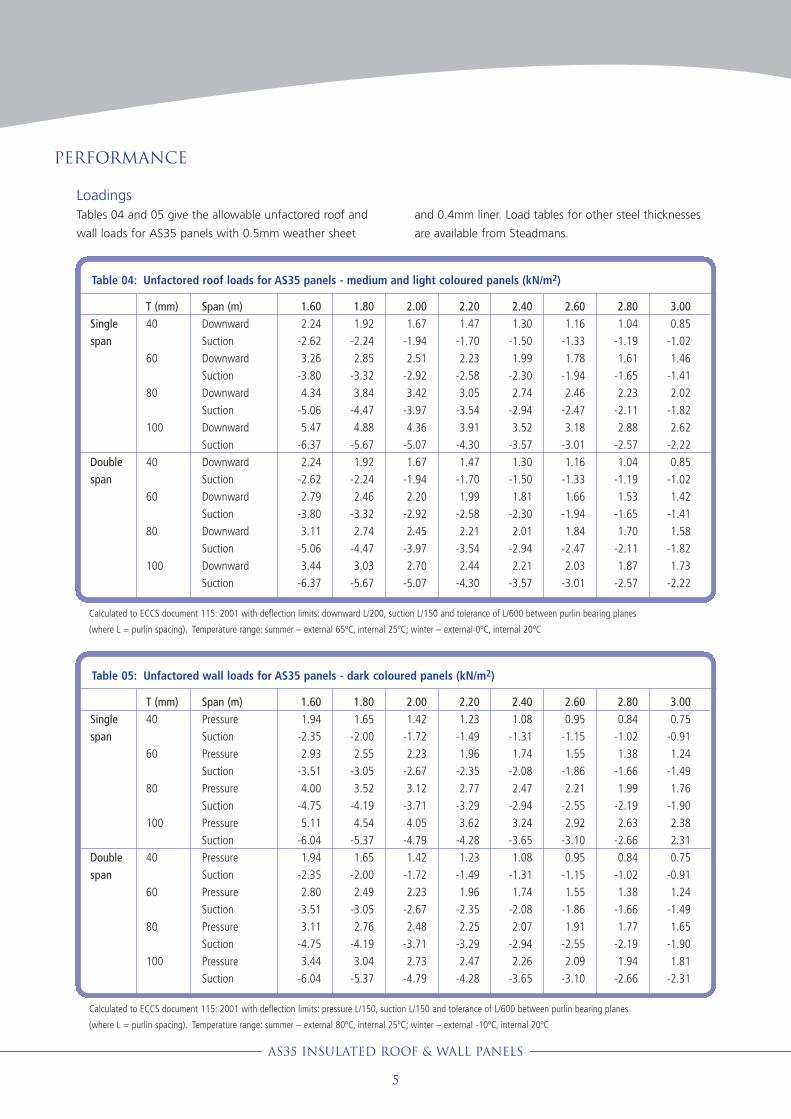
LoadingsTables 04 and 05 give the allowable unfactored roof and
wall loads for AS35 panels with 0.5mm weather sheet
and 0.4mm liner. Load tables for other steel thicknesses
are available from Steadmans.
Performance
Table 04: Unfactored roof loads for AS35 panels - medium and light coloured panels (kN/m2)
Singlespan
Doublespan
T (mm)40
60
80
100
40
60
80
100
Span (m)DownwardSuctionDownwardSuctionDownwardSuctionDownwardSuctionDownwardSuctionDownwardSuctionDownwardSuctionDownwardSuction
1.602.24
-2.623.26
-3.804.34
-5.065.47
-6.372.24
-2.622.79
-3.803.11
-5.063.44
-6.37
1.801.92
-2.242.85
-3.323.84
-4.474.88
-5.671.92
-2.242.46
-3.322.74
-4.473.03
-5.67
2.001.67
-1.942.51
-2.923.42
-3.974.36
-5.071.67
-1.942.20
-2.922.45
-3.972.70
-5.07
2.201.47
-1.702.23
-2.583.05
-3.543.91
-4.301.47
-1.701.99
-2.582.21
-3.542.44
-4.30
2.401.30
-1.501.99
-2.302.74
-2.943.52
-3.571.30
-1.501.81
-2.302.01
-2.942.21
-3.57
2.601.16
-1.331.78
-1.942.46
-2.473.18
-3.011.16
-1.331.66
-1.941.84
-2.472.03
-3.01
2.801.04
-1.191.61
-1.652.23
-2.112.88
-2.571.04
-1.191.53
-1.651.70
-2.111.87
-2.57
3.000.85
-1.021.46
-1.412.02
-1.822.62
-2.220.85
-1.021.42
-1.411.58
-1.821.73
-2.22
Calculated to ECCS document 115: 2001 with deflection limits: downward L/200, suction L/150 and tolerance of L/600 between purlin bearing planes
(where L = purlin spacing). Temperature range: summer – external 65ºC, internal 25ºC; winter – external 0ºC, internal 20ºC
Table 05: Unfactored wall loads for AS35 panels - dark coloured panels (kN/m2)
Singlespan
Doublespan
T (mm)40
60
80
100
40
60
80
100
Span (m)PressureSuctionPressureSuctionPressureSuctionPressureSuctionPressureSuctionPressureSuctionPressureSuctionPressureSuction
1.601.94
-2.352.93
-3.514.00
-4.755.11
-6.041.94
-2.352.80
-3.513.11
-4.753.44
-6.04
1.801.65
-2.002.55
-3.053.52
-4.194.54
-5.371.65
-2.002.49
-3.052.76
-4.193.04
-5.37
2.001.42
-1.722.23
-2.673.12
-3.714.05
-4.791.42
-1.722.23
-2.672.48
-3.712.73
-4.79
2.201.23
-1.491.96
-2.352.77
-3.293.62
-4.281.23
-1.491.96
-2.352.25
-3.292.47
-4.28
2.401.08
-1.311.74
-2.082.47
-2.943.24
-3.651.08
-1.311.74
-2.082.07
-2.942.26
-3.65
2.600.95
-1.151.55
-1.862.21
-2.552.92
-3.100.95
-1.151.55
-1.861.91
-2.552.09
-3.10
2.800.84
-1.021.38
-1.661.99
-2.192.63
-2.660.84
-1.021.38
-1.661.77
-2.191.94
-2.66
3.000.75
-0.911.24
-1.491.76
-1.902.382.310.75
-0.911.24
-1.491.65
-1.901.81
-2.31
Calculated to ECCS document 115: 2001 with deflection limits: pressure L/150, suction L/150 and tolerance of L/600 between purlin bearing planes
(where L = purlin spacing). Temperature range: summer – external 80ºC, internal 25ºC; winter – external -10ºC, internal 20ºC
ThermalThe PIR insulation within AS35 panels has a low thermal
conductivity that gives the panels their good thermal
performance (Table 07). The large panel dimensions and
the edge lap seals give AS35 panel systems good
resistance to air leakage.
BiologicalAS35 panels are unaffected by mould, fungi or mildew.
They do not support vermin.
AcousticSteadmans AS35 panels have a weighted sound reduction
Rw of between 22db and 25db in accordance with
BS EN ISO 140-3:1995.
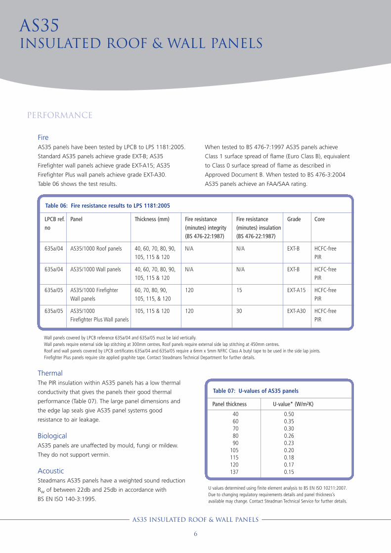
FireAS35 panels have been tested by LPCB to LPS 1181:2005.
Standard AS35 panels achieve grade EXT-B; AS35
Firefighter wall panels achieve grade EXT-A15; AS35
Firefighter Plus wall panels achieve grade EXT-A30.
Table 06 shows the test results.
When tested to BS 476-7:1997 AS35 panels achieve
Class 1 surface spread of flame (Euro Class B), equivalent
to Class 0 surface spread of flame as described in
Approved Document B. When tested to BS 476-3:2004
AS35 panels achieve an FAA/SAA rating.
AS35Insulated Roof & Wall panels
Performance
Table 06: Fire resistance results to LPS 1181:2005
LPCB ref.no
635a/04
635a/04
635a/05
635a/05
Panel
AS35/1000 Roof panels
AS35/1000 Wall panels
AS35/1000 Firefighter Wall panels
AS35/1000Firefighter Plus Wall panels
Thickness (mm)
40, 60, 70, 80, 90,105, 115 & 120
40, 60, 70, 80, 90,105, 115 & 120
60, 70, 80, 90,105, 115, & 120
105, 115 & 120
Fire resistance(minutes) integrity(BS 476-22:1987)
N/A
N/A
120
120
Fire resistance(minutes) insulation(BS 476-22:1987)
N/A
N/A
15
30
Grade
EXT-B
EXT-B
EXT-A15
EXT-A30
Core
HCFC-free PIR
HCFC-free PIR
HCFC-free PIR
HCFC-free PIR
Wall panels covered by LPCB reference 635a/04 and 635a/05 must be laid vertically.Wall panels require external side lap stitching at 300mm centres. Roof panels require external side lap stitching at 450mm centres. Roof and wall panels covered by LPCB certificates 635a/04 and 635a/05 require a 6mm x 5mm NFRC Class A butyl tape to be used in the side lap joints.Firefighter Plus panels require site applied graphite tape. Contact Steadmans Technical Department for further details.
Table 07: U-values of AS35 panels
U values determined using finite element analysis to BS EN ISO 10211:2007.Due to changing regulatory requirements details and panel thickness’savailable may change. Contact Steadman Technical Service for further details.
AS35 Insulated Roof & Wall panels
6
Panel thickness
4060708090
105115120137
U-value* (W/m2K)
0.500.350.300.260.230.200.180.170.15

DurabilityAS35 panels have a predicted service life of
40 years. Time to first maintenance depends
upon the finish and the environmental
conditions but can be as high as 30 years.
Coatings will degrade more rapidly in
industrial or marine air conditions and dark
finishes will fade more rapidly than light ones.
Table 08 gives the time to first repainting for
panels finished with standard Plastisol colours.
Service life can be increased by treating cut
edges with site applied touch up paint at the
time of cutting and by following the guidance
on inspection and maintenance on page 34
of this brochure.
Table 09 shows available standard colours.
Special colours are also available, contact
Steadmans for more details.
Performance
AS35 Insulated Roof & Wall panels
7
Group 1: Bamboo, Buttermilk, Goosewing Grey, Ivory, Merlin Grey,Moorland Green, Mushroom, New Grey, Olive Green, Pigeon Grey,Wedgwood Blue, White, Willow.
Group 2: Black, Cornflower Blue, Country Green, Golden Glow, Golden Yellow,Forest Green, Jade, Juniper Green, Linden Green, New Red,Ocean Blue, Pacific Blue, Poppy Red, Saffron, Sage Green, Slate Blue,Tangerine Orange, Terracotta, Vandyke Brown.
Colours below include nearest BS ref for guidance only as the colours vary slightly
from British Standard. Due to limitations in printing, colours are for guidance only
- specification should be made from an actual sample, available from Steadmans.
Table 08: Life to first full repainting for plastisol coated profiles
Colours
Group 1
Group 2
Roof profiles
Inland Coastal*
25 20
20 15
Table based on data
from Dobel. Steel
from other producers
may have different
durability values.
Wall profiles
Inland Coastal*
30 25
25 20
*within 1.5 miles from lake or sea shoreline
Table 09: Standard profile colours
Goosewing Grey* 10A05
Mushroom 10B19
Slate Blue* 18B29
Ivory RAL9002
Olive Green 12B27
Terracotta* 04C39
Merlin Grey* 18B25
Juniper Green* 12B29
Vandyke Brown* 08B29
Moorland Green 12B21
Ocean Blue 18C39
White 00E55
*Also available in Polyester coated finish
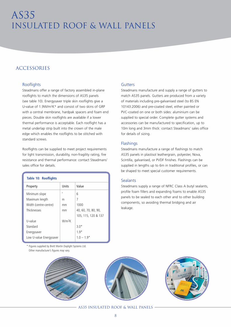
RooflightsSteadmans offer a range of factory assembled in-plane
rooflights to match the dimensions of AS35 panels
(see table 10). Energysaver triple skin rooflights give a
U-value of 1.9W/m2K* and consist of two skins of GRP
with a central membrane, hardpak spacers and foam end
pieces. Double skin rooflights are available if a lower
thermal performance is acceptable. Each rooflight has a
metal underlap strip built into the crown of the male
edge which enables the rooflights to be stitched with
standard screws.
Rooflights can be supplied to meet project requirements
for light transmission, durability, non-fragility rating, fire
resistance and thermal performance: contact Steadmans’
sales office for details.
GuttersSteadmans manufacture and supply a range of gutters to
match AS35 panels. Gutters are produced from a variety
of materials including pre-galvanised steel (to BS EN
10143:2006) and pre-coated steel, either painted or
PVC-coated on one or both sides: aluminium can be
supplied to special order. Complete gutter systems and
accessories can be manufactured to specification, up to
10m long and 3mm thick: contact Steadmans’ sales office
for details of sizing.
FlashingsSteadmans manufacture a range of flashings to match
AS35 panels in plastisol leathergrain, polyester, Nova,
Scintilla, galvanised, or PVDF finishes. Flashings can be
supplied in lengths up to 6m in traditional profiles, or can
be shaped to meet special customer requirements.
SealantsSteadmans supply a range of NFRC Class A butyl sealants,
profile foam fillers and expanding foams to enable AS35
panels to be sealed to each other and to other building
components, so avoiding thermal bridging and air
leakage.
AS35Insulated Roof & Wall panels
ACCESSORIES
AS35 Insulated Roof & Wall panels
8
Table 10: Rooflights
Property
Minimum slope
Maximum length
Width (centre-centre)
Thicknesses
U-value
Standard
Energysaver
Low U-value Energysaver
Units
˚
m
mm
mm
W/m2K
Value
6
7
1000
40, 60, 70, 80, 90,
105, 115, 120 & 137
3.0*
1.9*
1.0 – 1.9*
* Figures supplied by Brett Martin Daylight Systems Ltd.
Other manufacturer’s figures may vary.

Design guidance
AS35 Insulated Roof & Wall panels
9
StructureAS35 panels are designed to be supported by and fixed to
steel or timber purlins. Steelwork for AS35 panels should
be within the tolerances given in BS 5950-2:2001: fixing
planes on adjacent purlins should be less than L/600 apart
(where L is the purlin spacing).
All AS35 panels are suitable for spanning purlins at 1.8m
centres. Consult Steadmans Technical Department for
guidance on using the panels on purlins at centres greater
than 1.8m.
AS35 panels should be isolated from preservative treated
timber purlins by PVC barrier tape applied to the bearing
face of the purlins.
FixingsFixings for AS35 roof panels provide restraint against wind
uplift forces; those for AS35 wall panels provide restraint
and support.
Whilst panels may be fixed through valleys or crowns,
Steadmans recommend valley fixing: accurate fixing is
easier to achieve, loads on the fixings are smaller, the
fixings are less likely to distort the weather sheet, and
better compression of the sealant is achieved at end laps.
Fixings should be stainless steel or carbon-steel self drilling
screws with a high thread to restrain the weather face of
the panel and should have press-on or integral caps to
match the finish of the panel. To prevent water
penetration each fixing should have a 19mm diameter
EPDM washer.
Fixings to light and heavy section steel should pass
through the steel and leave 5mm of thread exposed on
the underside of the section. Fixings to timber must
achieve a minimum 40mm embedment.
For normal exposure conditions AS35 roof and wall panels
should be fixed in each main valley at each purlin
(see figure 02): consult Steadmans Technical Department
for guidance on abnormal conditions.
Figure 02: Fixing details for roof and wall panels
Standard fixing positions (roof and wall panels)
End lap fixing positions - showing positions of tail stitchers (roof panels)
Eaves fixing positions (roof panels)

LapsSide laps between panels are formed by lapping the
extended weather sheet of the female side of one panel
over the male crown of the adjacent panel. The exposed
edge of the lap should face away from the prevailing
wind. The lap should be sealed with butyl sealant strip
6mm wide by 5mm high and the two weather sheets
stitched with 23mm long self-drilling screws. AS35 roof
panels should be stitched at 450mm centres, AS35 wall
panels should be stitched at 300mm centres.
End laps are required on large span roofs and high walls
with two or more tiers of AS35 panels. Roof panel end
laps are formed by lapping the weather sheet of the
upper panel 150mm over the lower panel. End laps are
sealed with three runs of butyl sealant 6mm wide by
5mm high. The first run should be sited 10 - 15mm
upslope of the primary fixings, the second run 10 - 15mm
downslope of the primary fixings and the third run 15mm
from the bottom of the lap. Wall panel end laps are
formed by lapping the weather sheet of the upper panel
100 mm over the lower panel. End laps are sealed with
two runs of butyl sealant 6mm wide by 5mm high. The
first run should be sited 10 - 15mm upwards of the
primary fixings, the second run 15mm from the bottom of
the lap (see fig 27 on page 25).
Where four panels overlap additional runs of butyl sealant
are required between the male and female crowns of all
four panels to prevent air leakage.
FireAS35 panels provide class 0 resistance to surface spread
of flame and can be used to form roof and wall linings
without any additional treatment.
AS35 roof panels achieve an AA rating against external
spread of fire and may be used at any location on the
roof. AS35 wall panels achieve LPCB grade EXT-B and,
in England and Wales, and Northern Ireland, may be used
without restriction on walls at least 1m from a boundary
(see AD B section 13 for details of boundary conditions).
Walls within 1m of a boundary should be clad with AS35
Firefighter panels which achieve LPCB grade EXT-A15 and
will provide 120 minutes of integrity and 15 minutes of
insulation. To achieve the ratings panels must be fixed at
every valley and have laps stitched at 450mm centres
(roofs) and 300mm centres (walls).
In Scotland AS35 firefighter panels may be used on walls
at least 1m from a boundary; AS35 firefighter plus panels
should be used on walls within 1m of a boundary - these
achieve LPCB grade EXT-A30 and provide 120 minutes
integrity and 30 minutes of insulation. See Scottish
Building Standards Technical Handbook Section 2 for
details of boundary conditions.
Hot flues which penetrate the panels must be separated
from the panel cores by 25mm and the gap packed with
nonflammable material: pre-formed collars are available.
AS35Insulated Roof & Wall panels
Design guidance
AS35 Insulated Roof & Wall panels
10
Figure 03: End lap fixing details - roof panels Figure 04: Side lap fixing details - roof and wall panels
Panel fastener with19mm washer
Tail stitcher
3 rows 6 x 5mmButyl seal
150mm lap
23mm stitching screwswith 16mm washers
6 x 5mm Butyl air seal

Thermal performanceCarbon emissions from non-domestic buildings must now
be an aggregate 25% lower than those predicted for a
comparable building which would have met the
requirements of Part L 2006. Energy use and emissions
must be calculated using the Simplified Building Energy
Model (SBEM), either by using iSBEM (a free software tool
available from the DCLG) or by using an accredited
simulation tool.
Whilst designers will now have to consider building form,
efficiency of services and the use of low or zero carbon
energy generation they will still have to address fabric
heat losses:
Conduction losses: Part L no longer uses elemental U-
values for assessing compliance. The low U-values
provided by AS35 panels give designers a way of
addressing fabric heat loss.
Thermal bridging: SBEM takes account of heat losses at
junctions between building elements using linear thermal
transmittance (psi values). Psi values for junctions and
perimeters in the AS35 panel system are shown in
table 11.
Air leakage: whilst the regulations set an air leakage
limit of 10m3/m2/hr @ 50Pa, designers may choose to
base their SBEM calculations upon lower rates.
When correctly detailed and installed the AS35 panel
system will contribute to achieving a low air leakage rate.
Work which involves increasing the capacity of building
services in existing buildings (described in Approved
Document L2B) may require improvements to the thermal
performance of building elements. One means of
achieving that would be to replace existing roof or wall
panels with an AS35 panel system.
Control of condensationPart C2 of the Building Regulations requires designers to
prevent harmful condensation forming on or within
building elements. To minimise the risk of condensation
designers should arrange for the extraction at source of
moisture generated by activities and processes within the
building and adopt forms of construction with will not
trap moisture within elements. Designers should observe
the guidance in BS 5250:2002.
AS35 panels are unlikely to be affected by surface
condensation as the high performance core will keep the
temperature of the liner sheet above dewpoint. Designers
should assess the risk of surface condensation at linear
thermal bridges using the the method in BRE IP 17/01 and
the temperature factors (f-values) shown in table 11.
The high vapour resistance of the liner sheet and the
factory applied edge seal will inhibit interstitial
condensation.
Design guidance
Table 11 Psi & f-values for panel junctions and perimeters
Junction
Eaves (fig 05)
Ridge (fig 09)
Verge (fig 11)
Valley gutter* (fig 15)
Parapet gutter (fig 17)
Parapet (fig 19)
Wall - drip (fig 29)
Wall - int corner (fig 30)
Wall - ext corner (fig 31)
Door/window jamb (fig 34)
Door/window head (fig 35)
Window cill (fig 36)
Industrial door head
Industrial door jamb
Psi value (W/mK)
0.23
0.01
0.19
0.62
1.20
0.37
0.30
0.23
0.26
0.49
0.50
0.49
0.87
0.41
f-value
0.83
0.97
0.76
0.73
0.71
0.65
0.76
0.76
0.76
0.59
0.58
0.60
0.67
0.74
AS35 Insulated Roof & Wall panels
11
* use twice the value for a full gutterNote that values are only applicable to the components on the detail. Changes to the detail will alter values

AS35Insulated Roof & Wall panels
AS35 Insulated Roof & Wall panels
12
DrainageAS35 panels are intended for roofs with a minimum slope
of 4º: if the roof includes rooflights the minimum slope
is 6˚. Gutters and downpipes should be designed to
collect rain and snow falling on the roof and discharge it
safely. Drainage capacity should be determined according
to BS EN 12056-3:2000.
The U-values of an insulated gutter should be slightly
higher than that of the roof panels to ensure snow and
ice melts first in the gutter.
RooflightsIlluminance: the area of rooflights required to illuminate
the building interior depends upon the type of activities
taking place. BS 8206-2:2008 Code of practice for
daylighting gives guidance. Table 12 shows how to
achieve the recommended levels.
Thermal performance: with the adoption of the whole
building compliance method in Part L there is no
maximum permitted area for rooflights: designers must
assess the performance of rooflights as part of the SBEM
evaluation. The only limit on rooflights is that their area
weighted U-value must not exceed 2.2W/m2K and no
rooflight may have a U-value worse than 3.3W/m2K.
Solar gain: Part L requires designers to ensure solar gains
in summer will not be excessive. TM37 contains guidance
and calculations methods.
Safety: rooflights must provide safety levels appropriate
to the frequency of roof access. All Steadmans rooflights
offer a non-fragility rating of class B on installation.
However, for standard 2.4 kg gauge rooflights that level
of non-fragility may not be maintained over their 25 year
service life. Where rooflights must be non-fragile
throughout their service life Steadmans recommend the
use of 3.0 kg gauge rooflights. Consult Steadmans for
further guidance.
Design guidance
Table 12: Rooflight areas
Characteristics of activity /interior
Interiors used occasionally,
with visual tasks confined
to movement and limited
perception of detail
e.g. bulk stores
Continuously occupied
interiors, with visual tasks
not requiring perception of
detail e.g. loading bays,
plant rooms
Moderately difficult visual
tasks, colour judgement
may be required e.g. sports
and assembly halls,
packing, general offices,
engine assembly, retail
shops
Difficult visual tasks,
accurate colour judgement
required e.g. drawing
offices, inspection,
electronic assembly
Level ofilluminancereq. (lux)
100
200
300 - 500
750 - 1000
Recommendedmin. rooflightarea (% offloor area
10%
10%
13% - 15%
17% - 20%
*Table based on research by Institute of Energy and Sustainable
Development, De Montford University for illuminance in the horizontal
plane - rooflight area should be greater where illumination is needed in
the vertical plane e.g. where vertical racking is used.
** Figures for the level of illuminance required are taken from CIBSE
Guide A (table 1.12)

DESIGN DETAILS
This section sets out common
details for AS35 panels.
All the details here are
available in CAD format from
the Steadmans web site.
Figure 06
Boundary wall secret gutter
Figure 05
External trimline gutter
h
i
j
a
b
c
d
d
e
f
g
b
i
d
c
ad
k
l
e
Notes
• Factory formed insulated gutter, PIRboard insulation gives U-values of0.25 or 0.35W/m2K
AS35 Insulated Roof & Wall panels
13
Key to figures 05 & 06
a AS35 insulated roof panel
b AS35 insulated wall panel
c Profiled foam filler sealed with gun
grade mastic
d Air seal - 8mm Butyl rubber
e Seal - 6 x 5mm Butyl rubber
f Gutter support arm @ 1000mm
max. centres stitched to roof
panel @ max. 200mm centres
g Site applied fire rated canister
insulation
h Plastisol external eaves gutter
i Eaves beam
j Eaves flashing
k PIR insulation board
l Insulated gutter

AS35Insulated Roof & Wall panels
AS35 Insulated Roof & Wall panels
14
DESIGN DETAILS
Figure 08
Crimped curved ridge
Figure 07
Crimped curved eaves
i
d
c
a
Key to figures 07 & 08
a AS35 insulated roof panel
b AS35 insulated wall panel
c Profiled foam filler sealed with gun
grade mastic
d Air seal - 8mm Butyl rubber
e Seal - 6 x 5mm Butyl rubber
f Curved single skin sheet
g Rockwool insulation to achieve
required U-value
h Galvanised support for liner sheet
i Side rail
j 0.7mm site curved flat sheet,
min 75mm sealed lap joints
k Closure flashing
l insulated gutter
d
l
b
e
f
g
h
j
k
a
b
e
e
f
g
j
h
h
i
d
d
Notes
• Factory formed insulated gutter, PIRboard insulation gives U-values of0.25 or 0.35W/m2K
• Minimum outside radius of curvedeaves sheet = 450mm

Figure 09
Standard ridge
Figure 10
Curved ridge
a
d
ah
j
Key to figures 09 & 10
a AS35 insulated roof panel
b Ridge flashing with min. 150mm
sealed lap joints
c Profiled foam filler sealed with gun
grade mastic
d Air seal - 8mm Butyl rubber
e Seal - 6 x 5mm Butyl rubber
f Site applied fire rated canister
insulation
g Internal liner flashing with min
75mm sealed lap joints
h Cranked single skin ridge sheet
i PIR insulation board with site
applied fire rated canister insulation
j Internal flashing with min. 75mm
sealed lap joints
d
c b f
g d
d
ei
AS35 Insulated Roof & Wall panels
15

AS35Insulated Roof & Wall panels
AS35 Insulated Roof & Wall panels
16
DESIGN DETAILS
Figure 12
Verge to brick wall
Key to figures 11 & 12
a AS35 insulated roof panel
b AS35 insulated wall panel
c Profiled foam filler sealed with gun
grade mastic
d Air seal - 8mm Butyl rubber
e Seal - 6 x 5mm Butyl rubber
f Site applied fire rated canister
insulation
g Internal liner flashing with min.
75mm sealed lap joints
h Cleader rail
i Verge flashing
j Site applied expandable seal
k Wall strap (if required)
j
k
i
d
c
b
ef
g
h
b
c
d e f
g
h
i
i
def
g
d e f
g
i
a
j
k
Direction of lay
Direction of prevailing wind
Direction of lay
Direction of prevailing wind
Notes
• Designers must ensure that walls havean appropriate thermal performance
a
Figure 11
Verge to wall panels

AS35 Insulated Roof & Wall panels
17
Figure 14
Hip ridge
Key to figures 13 & 14
a AS35 insulated roof panel
b Flashing chased into brickwork,
sealed with 6 x 5mm Butyl rubber
c Profiled foam filler sealed with gun
grade mastic
d Air seal - 8mm Butyl rubber
e Support zed sealed top and bottom
with 6 x 5mm Butyl rubber seal
f Apron flashing sealed with
6 x 5mm Butyl rubber seal
g Internal liner flashing sealed to wall
with expandable seal
h Site applied fire rated canister
insulation
i Wall strap (if required)
j Hip flashing with min. 150mm
sealed lap joints or butt straps
k Internal liner flashing with min.
75mm sealed lap joints
l Cleader rail
m Hip rafter
i
f e
g
f
g
ah h
b b
i
jh
d
m
a
l
k c
d
l
Notes
• Designers must ensure that walls have an appropriate thermal performance
• Panels and profiled foam filler skew-cut to suit hip rake angle
• Cleader rail by steel sub-contractor
dd
Figure 13
Abutment

AS35Insulated Roof & Wall panels
AS35 Insulated Roof & Wall panels
18
DESIGN DETAILS
Figure 15
Eaves valley
Figure 16
Hip valley
Key to figures 15 & 16
a AS35 insulated roof panel
b Double sided plastisol flashing
(optional)
c Insulated gutter
d Air seal - 8mm Butyl rubber
e Seal - 50 x 6mm Butyl rubber
f Gutter outlet
g Eaves beam
h Purlin
i Cleader rail
j Hip rafter
d
c
d
e fg
h
a
j
d
c
da
i
b
i
Notes
• Factory formed insulated gutter, PIRboard insulation gives U-values of0.25 or 0.35W/m2K
• Edge protection lacquer can be appliedto panels cut on site to suit rake angle
• Gutter outlet offset to miss eaves beam
• Cleader rail by steel sub-contractor

AS35 Insulated Roof & Wall panels
19
Figure 17
Boundary wall secret gutter
Figure 18
Parapet with secret gutter
Notes
• Factory formed insulated gutter, PIRboard insulation gives U-values of0.25 or 0.35W/m2K
• Designers must ensure that walls havean appropriate thermal performance
Key to figures 17 & 18
a AS35 insulated roof panel
b AS35 insulated wall panel
c Profiled foam filler sealed with gun
grade mastic
d Air seal - 8mm Butyl rubber
e PIR insulation board sealed with site
applied fire rated canister insulation
f Site applied fire rated canister
insulation
g Insulated gutter
h Cap flashing
i Metal flashing set into brickwork,
sealed with gun grade silicone mastic
j Gutter sealed to wall with 8mm Butyl
rubber seal
c
d
e
a
b
f
g
dd
a
gj
i
d
c
c
d
h
AS35Insulated Roof & Wall panels
AS35 Insulated Roof & Wall panels
20
DESIGN DETAILS
j
e a
c
b
f
g
h
dc
i eh
d dk k
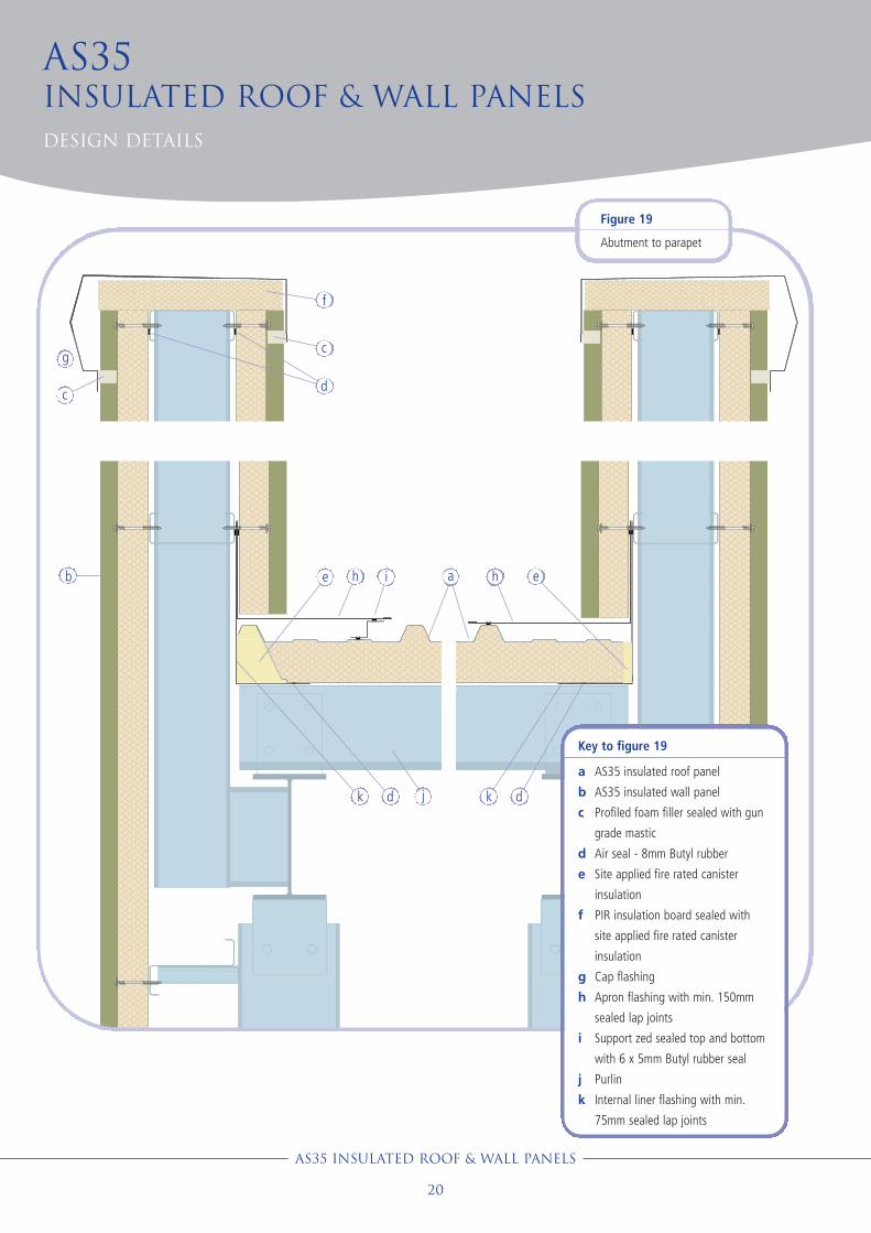
Figure 19
Abutment to parapet
Key to figure 19
a AS35 insulated roof panel
b AS35 insulated wall panel
c Profiled foam filler sealed with gun
grade mastic
d Air seal - 8mm Butyl rubber
e Site applied fire rated canister
insulation
f PIR insulation board sealed with
site applied fire rated canister
insulation
g Cap flashing
h Apron flashing with min. 150mm
sealed lap joints
i Support zed sealed top and bottom
with 6 x 5mm Butyl rubber seal
j Purlin
k Internal liner flashing with min.
75mm sealed lap joints

Figure 20
Mono ridge to brickwork
Figure 21
Mono ridge to wall panel
Figure 22
Lean-to roof
Key to figures 20, 21 & 22
a AS35 insulated roof panel
b AS35 insulated wall panel
c Profiled foam filler sealed with gun
grade mastic
d Site applied expandable seal
e Site applied fire rated canister
insulation
f Mono ridge flashing with min.
150mm sealed lap joints
g Rafter built into wall
h Metal flashing chased into masonry,
sealed with gun grade mastic
i Apron flashing with min. 150mm
sealed lap joints
j Purlin
a
cf
e
b
a
c
f
ac
j
i
h
g
j
g
c
AS35 Insulated Roof & Wall panels
21
d
Notes
• Designers must ensure that walls havean appropriate thermal performance

AS35Insulated Roof & Wall panels
AS35 Insulated Roof & Wall panels
22
DESIGN DETAILS
Figure 24
Change in roof slope
Figure 23
Lean-to roof to wall paneld
e
b
ac
f
l
k
d
a
c
j
i
h
g
k
Key to figures 23 & 24
a AS35 insulated roof panel
b AS35 insulated wall panel
c Profiled foam filler sealed with gun
grade mastic
d Air seal - 8mm Butyl rubber
e Apron flashing with min. 150mm
sealed lap joints
f Expanding foam sealant
g Site applied mineral fibre insulation
h External flashing with min. 150mm
sealed lap joints
i Internal liner flashing with min.
75mm sealed lap joints
j Purlin on extended cleats (if req.)
k Purlin
l Side rail
b
d
ac
d

AS35 Insulated Roof & Wall panels
23
e
b
a
c
j
i
h
g
f
lk
Key to figure 25
a AS35 insulated roof panel
b AS35 insulated wall panel
c Profiled foam filler sealed with gun
grade mastic
d Air seal - 8mm Butyl rubber
e Site applied fire rated canister
insulation
f PIR insulation board with site
applied fire rated canister insulation
g Cap flashing with min. 150mm
sealed lap joint
h Apron flashing with min. 150mm
sealed lap joints
i Support zed sealed top and bottom
with 6 x 5mm Butyl rubber seal
j Drip flashing
k Soffit flashing sealed with site
applied fire rated canister insulation
l Corner flashing
m Internal liner flashing with min.
75mm sealed lap joints
Figure 25
Mansard - gableend of run
a
b
c
d
d
Figure 25
Mansard - gablestart of run
d
m
m

AS35Insulated Roof & Wall panels
AS35 Insulated Roof & Wall panels
24
DESIGN DETAILS
Figure 26
Mansard - side wall
e
ba
cji
h
g
e k
Key to figure 26
a AS35 insulated roof panel
b AS35 insulated wall panel
c Profiled foam filler sealed with gun
grade mastic
d Air seal - 8mm Butyl rubber
e Site applied fire rated canister
insulation
f PIR insulation board sealed with
site applied fire rated canister
insulation
g Cap flashing with min. 150mm
sealed lap joint
h Insulated gutter
i Drip flashing
j Soffit flashing
k Corner flashing
l Internal liner flashing with
min. 75mm sealed lap joints
b
c
cc
d
f
d
c
Notes
• Factory formed insulated gutter, PIR board insulation gives U-values of0.25 or 0.35W/m2K
d
d
l
b
b
AS35 Insulated Roof & Wall panels
25
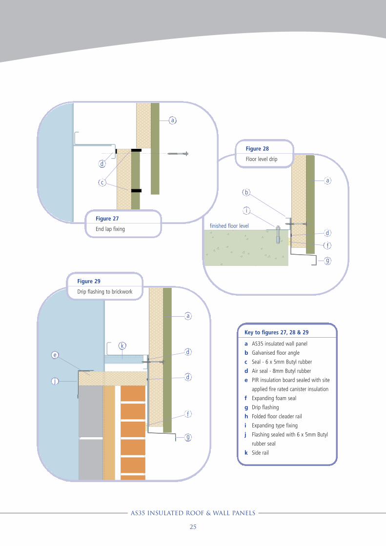
Key to figures 27, 28 & 29
a AS35 insulated wall panel
b Galvanised floor angle
c Seal - 6 x 5mm Butyl rubber
d Air seal - 8mm Butyl rubber
e PIR insulation board sealed with site
applied fire rated canister insulation
f Expanding foam seal
g Drip flashing
h Folded floor cleader rail
i Expanding type fixing
j Flashing sealed with 6 x 5mm Butyl
rubber seal
k Side rail
Figure 29
Drip flashing to brickwork
Figure 28
Floor level drip
Figure 27
End lap fixing
d
a
d
f
a
b
i
g
de
a
j
g
f
k
c
finished floor level
d

AS35Insulated Roof & Wall panels
AS35 Insulated Roof & Wall panels
26
DESIGN DETAILS
Key to figures 30 & 31
a AS35 insulated wall panel
b Expanding foam seal
c Internal corner flashing with
min. 150mm sealed lap joints
d Air seal - 8mm Butyl rubber
e Seal - 6 x 5mm Butyl rubber
f Profiled filler to close off top and
bottom of external corner flashing
g Site applied foam insulation
h Internal liner flashing with
min. 75mm sealed lap joints
i External corner flashing with
min. 150mm sealed lap joints
j Side rail
Figure 30
Wall - internal corner
b
a
c
d
e
a
i h
g
f
Figure 31
Wall - external corner
a
j
e
ad
e
d
dh

AS35 Insulated Roof & Wall panels
27
d
e
c
i
h
g
f
b hf
g
fa
b fad d
Figure 32
Wall panel to recessed brickwork
Key to figures 32 & 33
a AS35 insulated wall panel
b Internal corner flashing with
expanding foam seal to brickwork
and 6 x 5mm Butyl rubber seal to
panel
c External corner flashing sealed to
panel with 6 x 5mm Butyl rubber seal
d Galvanised support sealed with 8mm
Butyl rubber air seal
e PIR insulation board sealed with site
applied fire rated canister insulation
f Site applied fire rated canister
insulation
g Internal corner flashing sealed to
brickwork with expanding foam seal
h Support zed sealed to panel with
6 x 5mm Butyl rubber seal
i Side rail
Figure 33
Recessed wall panels

AS35Insulated Roof & Wall panels
AS35 Insulated Roof & Wall panels
28
Figure 35
Personnel door - head
Key to figures 34 & 35
a AS35 insulated wall panel
b Site applied expanding air seal
c LPC approved insulation board to
give required U-value, sealed with fire
rated canister insulation
d Galvanised door jamb / head
e 6 x 5mm Butyl rubber seal
f Polyethylene backing rod with
silicone sealer (by door installers)
g Door head flashing
h External door jamb flashing with no
connection to internal
i Optional external soffit flashing with
no connection to internal
j Optional internal flashing
k Optional external door jamb flashing
with no connection to internal
l Door and frame (fixed by others)
m 8mm Butyl rubber seal
DESIGN DETAILS
d
e ba
cj
h fl k
d
m
b
ac
j
gf
l
e
Figure 34
Personnel door - jamb

AS35 Insulated Roof & Wall panels
29
Figure 36
Window - head and cill
Figure 37
Window - jamb
d
b
ac
j
i
gf
m
l
d
e ba
cj
h
f l
k
Key to figures 36 & 37
a AS35 insulated wall panel
b Site applied expanding air seal
c LPC approved insulation board to
give required U-value, sealed with fire
rated canister insulation
d Galvanised window jamb / head
e 6 x 5mm Butyl rubber seal
f Polyethylene backing rod with
silicone sealer (by window installers)
g Window head flashing
h External window jamb flashing with
no connection to internal
i Cill flashing with 3˚ fall to allow for
drainage, no connection to internal
j Optional internal flashing
k Optional external window jamb
flashing with no connection to
internal
l Window unit fixed to galvanised
window jamb (by others)
m Profiled foam filler sealed top and
bottom with gun grade mastic
b
c
j
d
f
j
e

AS35Insulated Roof & Wall panels
AS35 Insulated Roof & Wall panels
30
DESIGN DETAILS
Figure 39
Roof panel over rooflight
Figure 40
Rooflight over roof panel
Figure 41
Rooflight over rooflight
Figure 38
Rooflight side laps
Key to figures 38 to 41
a AS35 insulated roof panel
b Factory assembled rooflight
c Factory fitted polyethylene filler
d Underlap strip
e 6 x 5mm Butyl rubber sidelap seal
f 6 x 5mm endlap sealant
g Fastener (through valley positions
only)
h Stitching screw
i Purlin and extension plate
j Gun applied silicon sealant
(ISO-11600-F-25LM) 15mm from
bottom of lap
e ba
d
h
g e ab
h
b
a
c
i
g
f
25mm
b
ac
i
g
f
bc
i
f
b
c
25mm
25mm
g
15mm
j
j
15mm
j
15mm

Handling and storage
AS35 panels are delivered to site in plastic wrapped packs
with end and side protection. The panels are packed with
weather faces together to reduce pack height. The height
of a pack and the number of panels it contains depends
upon the thickness of the panels (see table 13).
The packs can be off-loaded directly to the roof, or to a
storage area, which should be dry and well away from
traffic. Packs may be stacked up to 2.5m high with
wooden bearers every 2m: bearers should be placed
above each other.
Handle AS35 panels carefully to avoid marking the
weather sheet or liner. Lift panels from the pack - do not
drag them. Carry panels by the male (filled) edge - do not
lift panels by the female edge or just the top sheet.
See table 13 for the weight of panels.
Observe site health and safety procedures and the results
of manual handling and other assessments.
PreparationBefore fixing any panels check the squareness and
accuracy of the steelwork. Determine the direction of the
prevailing wind. Check panels for damage before fixing
and remove any excess insulation from side and end laps.
InstallationThese installation sequences describe the general methods
for laying and fixing AS35 roof and wall panels.
Single tier roof
1. Lay the first panel with the female edge to the gable,
away from the prevailing wind. Use a string line to lay
the panel straight and true. Fix the panel.
2. Apply 6 x 5mm butyl sealant along the top of the
male crown. The surfaces receiving the sealant must
be dry: joints in the sealant must be lapped by 25mm
not butted.
3. Lay the second panel with its female crown over the
male crown of the first panel. Fix the panel.
4. Stitch the lap with self drilling fixings.
5. Continue to lay panels along the roof, checking the
alignment of the cladding and correcting any
deviations.
6. Fix flashings. Use foam filler pieces and butyl sealant
to form weathertight junctions.
Sitework
AS35 Insulated Roof & Wall panels
31
Table 13 Handling data for AS35 roof and wall panel
Panel core thickness
Weight (kg/m)0.5/0.4 steel0.7/0.4 steel
Panels per pack (max.)
40mm 60mm 70mm 80mm 90mm 105mm 115mm 120mm 137mm
9.6 10.4 10.8 11.3 11.7 12.3 12.7 12.9 13.611.3 12.1 12.5 12.9 13.3 13.9 14.3 14.5 15.2
14 10 10 8 8 8 6 6 6

AS35Insulated Roof & Wall panels
Sitework
AS35 Insulated Roof & Wall panels
32
Double tier roof
On a two tier roof lay the panels in the order shown in
figure 45.
1. Lay panel one with the female edge to the gable,
away from the prevailing wind. Use a string line to lay
the panel straight and true. Fix the panel at every
purlin except the top one.
2. Apply three runs of 6 x 5mm butyl sealant to the
head of panel one, one on each side of the fixing line
and one 15mm from the end of the lap.
3. Apply a run of 6 x 5mm butyl sealant to the male
crown of panel one for the length of the lap
(figure 42).
4. Lay panel two with the female edge to the gable and
the tail lapping panel one. Fix the panel with one
fixing in each main valley at every purlin.
5. Tail stitch the end lap.
6. Apply a run of 6 x 5mm butyl sealant to the male
crown of panels one and two (figure 43).
7. Lay panel three with its female crown lapping the
male crown of panel one. Fix the panel at every
purlin except the top one.
8. Stitch the side lap with self drilling fixings at 450mm
centres.
9. Apply three runs of 6 x 5mm butyl sealant to the
head of the panel (as panel one).
10. Apply additional runs of 6 x 5mm butyl sealant along
the male and female crowns of panel three for the
length of the lap (figure 44).
11. Lay panel four with its female crown lapping the
male crown of panel two and its end lapping the
head of panel three. Fix the panel with one fixing in
each main valley at every purlin.
12. Stitch the side lap with self drilling fixings at 450mm
centres.
13. Tail stitch the end lap.
14. Continue to lay panels along the roof, checking the
alignment of the cladding and correcting any
deviations.
15. Fix flashings. Use foam filler pieces and butyl sealant
to form weathertight junctions.
Figure 42: Sealant to panel one
Figure 43: Sealant over panels one & two
additional runs of butyl sealant
full run of butyl sealant
Figure 44: Sealant to panel three
additional run of butyl sealant

Sitework
Wall panels
1. Set the first panel upright against the framing at the corner of the building
with the female edge to the corner. Make sure the panel is vertical.
2. Fix with one fixing in each main valley at each side rail.
3. Apply a run of 6 x 5mm butyl sealant along the male crown.
4. Set the second panel upright with its female edge lapping the male edge of
panel one.
5. Fix with one fixing in each main valley at each side rail.
6. Stitch the lap with self drilling fixings at 300mm centres.
7. Continue to lay panels along the wall, checking the alignment of the cladding
and correcting any deviations.
8. Fix flashings. Use foam filler pieces and butyl sealant to form weathertight
junctions.
AS35 Insulated Roof & Wall panels
33
Cutting panelsWhere panels have to be cut on
site:
• Use a powered
reciprocating or circular
saw. Do not use an abrasive
cutting wheel.
• Support the panel along
the line of the cut.
• Protect the pre-coated
finishes of the panel.
• Clean any swarf or debris
from the pre-coated finish
of the panel immediately.
CompletionWhen all the AS35 panels have
been installed check:
• All fixings are correctly
fitted and tightened;
• The fixings do not distort
the panels;
• All fixing caps are fitted;
• Minor scratches have been
treated;
• The surface of the roof is
clean and free of any swarf
or debris.
ridge flashing
internal ridge flashing
direction ofinstallation
direction of installation direction of installation
direction ofinstallation
direction ofprevailing wind
direction ofprevailing wind
1
3
5
7
2
4
6
2
4
6
1
3
5
7
Figure 45: Roof panel laying sequence

AS35Insulated Roof & Wall panels
Annual inspectionIt is good practice to carry out
annual inspection of the building
exterior and to carry out any
remedial work identified during
the inspection, see table 14.
Touch-upMinor scuffing to the colour
coating should not be treated.
Deeper scratches which reach
the substrate should be repaired
with touch-up paint. The touch-
up paint should only be applied
to the original scratch using a
fine paint brush. As touch-up
paint will dry to a slightly
different colour than the original
coating the area which is
touched up should be kept as
small as possible.
Maintenance
AS35 Insulated Roof & Wall panels
34
Table 14 Checklist for annual inspection
Check for:
Blocked gutters, which may
cause overflow into the
building.
Build-up of debris, which can
retain water and cause
corrosion.
Dirt retention on areas not
washed by rainwater: that
affects the appearance of the
building and, if left untreated,
could cause the coating to
breakdown.
Mould growth, which is rare,
but can affect the appearance
of the building.
Local damage - breakthrough
of the panel coating could
result in corrosion of the
substrate.
Drilling swarf and fixing
debris.
Condition of fixings - faulty
fixings can cause leaks or rust
staining on the surface of the
panels.
Corrosion of cut edges.
Remedial action:
Clean gutters and wash out any
blockage.
Remove debris.
Wash down with fresh water using a
hose and soft bristle brush. Heavy
deposits can be removed with a solution
of water and household detergent or
proprietary cleaner.
Wash down, then apply a cleansing
solution: consult Steadmans Technical
Department for guidance.
Assess the extent of the damage and
either touch up (see opposite) or over-
paint the affected area or replace
damaged sheets.
Remove debris.
Replace faulty fixings and missing clips.
Cut or abrade edges back to clean bright
metal and repaint: consult Steadmans
Technical Department for guidance.
Supply and delivery
AS35 panels are available directly
from Steadmans. AS35 panels
are supplied in plastic wrapped
packs: fully timber crated packs
are available for sea freight
shipping at additional cost.
AS35 panels are usually delivered
to site. Off loading is the
responsibility of the customer.
Delivery by self off-load vehicles
can be arranged.

AS35 Insulated Roof & Wall panels
35
Steadmans offers comprehensive technical support
to designers and contractors working with AS35
panels, including:
• technical brochures and data sheets for all
Steadmans products
• CAD details
• copies of test certificates
• loading calculations
• design and installation guidance
Our web site offers full product and application
information and downloads of construction details
in AutoCAD and PDF formats.
www.steadmans.co.ukTo contact our Technical Department:
• telephone: 01697 478 277
• fax: 01697 478 530
• email: [email protected]
Technical support
references
• Approved Documents
- A Structure
- B Fire safety
- C Site preparation and resistance to
contaminants and moisture
- L2A Conservation of fuel and power in new
buildings other than dwellings
- L2B Conservation of fuel and power in
existing buildings other than dwellings
• The Scottish Building Standards: Technical
Handbook - Non-domestic
• TM 37: Design for improved solar shading.
2006
• MRCMA Technical paper 14. Guidance for the
design of metal roofing and cladding to
comply with Approved Document L2: 2001.
• BS 476 Fire tests on building material and structures.
- BS 476-3:2004 Classification and method of test for
external fire exposure to roofs.
- BS 476-7:1997 Method of test to determine the
classification of the surface spread of flame of products.
- BS 476-22:1987 Methods for determination of the fire
resistance of non-loadbearing elements of construction.
• BS 5250:2002 Code of practice for control of condensation in
buildings.
• BS 5950 Structural use of steelwork in building.
- BS 5950-2:2001 Specification for materials, fabrication and
erection. Rolled and welded sections.
• BS 8206 Lighting for buildings.
- BS 8206-2:2008 Code of practice for daylighting.
• BS EN 10143:2006 Continuously hot-dip coated steel sheet
and strip. Tolerances on dimensions and shape.
• BS EN 10346:2009 Continuously hot-dip coated steel flat
products. Technical delivery conditions.
• BS EN 12056 Gravity drainage systems inside buildings.
- BS EN 12056-3:2000 Roof drainage, layout and calculation.
• BS EN ISO 10140 Acoustics. Laboratory measurement of
sound insulation of building elements.
- BS EN ISO 10140-2:2010 Measurement of airborne
sound insulation.
• BS EN ISO 10211:2007 Thermal bridges in building
construction. Heat flows and surface temperatures. Detailed
calculations.
• BS EN ISO 13788:2002 Hygrothermal performance of building
components and building elements. Internal surface
temperature to avoid critical surface humidity and interstitial
condensation. Calculation methods.
• LPS 1181:2005 Part 1 Issue 1.1: Series of Fire Growth Tests
for LPCB Approval and Listing of Construction Product
Systems - Part 1: Requirements and Tests for Built-Up
Cladding and Sandwich Panel Systems for Use as the External
Envelope of Buildings.
• ECCS document 115:2001 European recommendations for
the design of sandwich panels.

www.steadmans .co.uk
A. Steadman & Son
England & Wales
Warnell, Welton
Carlisle
Cumbria
CA5 7HH
Tel: 01697 478 277
Fax: 01697 478 530
E-mail: [email protected]
Online: www.steadmans.co.uk
Northern Ireland & Ireland
Unit 5, Scarva Road Ind. Est.
Banbridge, Co. Down
Northern Ireland
BT32 3QD
Tel: 02840 660 516
Fax: 02840 660 517
Scotland
New Edinburgh Road
View Park
Uddingston
G71 6LL
Tel: 01506 437 753
Fax: 01506 440 716
Mill of Crichie
Fyvie, Turriff
Aberdeenshire
AB53 8QL
Tel: 01651 891 668
Fax: 01651 891 698
ENVIRONMENTAL CREDENTIALS
We recognise the need to manage the impact which our business and processes have on the environment.
We believe we have a responsibility to contribute to the well-being of the communities we live in.
We are committed to providing a clean, safe environment.
Developing sustainable construction methods presents a challenge to the whole construction industry.
Our main raw material, steel, is eminently recyclable: 85 - 90% of steel from demolition goes for
re-use and 40% of steel used in new construction has been recycled.
By using modern machinery and upgrading our facilities we are continually reducing
the impact of our products on the environment, and improving their contribution
to the long-term performance of buildings.