AS Physics Unit 1 4 Electric Current - Animated Science
94
AS Physics Unit 1 4 Electric Current Mr D Powell
Transcript of AS Physics Unit 1 4 Electric Current - Animated Science

AS Physics Unit 1 4 Electric Current
Mr D Powell

Mr Powell 2009 Index
Chapter Map

Mr Powell 2009 Index
4.1 Current & Charge
Specification link-up 3.1.3: Charge, current and potential difference What is an electric current? How can we calculate the charge flow in a circuit? What are charge carriers?

When electrons move through a wire we call it an electrical current. It has a simple definition which leads to 1A = 2 x10⁻⁷Nm-1 or 1A = 1Cs-1
Units of Electrical Current

When electrons move through a wire we call it an electrical current. The electrons move as there is a potential difference.
The larger the p.d. the higher the current flow or Coulombs per second.
1A = 1Cs-1
A simple graph of this process would be where a steady
current has flowed for 20s seconds;
The number of Coulombs of charge that have flowed is 100C
Current Flow Basics
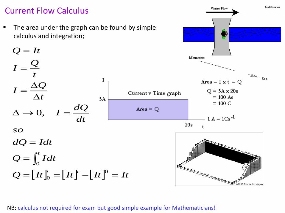
The area under the graph can be found by simple calculus and integration;
Current Flow Calculus
ItItItItQ
dtIQ
IdtdQ
so
dt
dQI
t
QI
t
QI
ItQ
tt
t
0
0
0
,0
NB: calculus not required for exam but good simple example for Mathematicians!

This process whereby ions exchange electrons through a molten liquid or dissolved solid is also a way in which a “current” flows. Also a PD between ground and cloud causing a spark to move.
As charge carriers are moving. Hence we can say that energy converted is;
E = QV E = 5C x 3000V = 15000J or E = VIt E = 3V x 2A x 3s E = 18J
GCSE Background – Electrolysis / Static
Make a note of these…

Potential Difference (chemical cells)
One way of separating charges is a chemical cell;
1) Two chemical pastes are separated 2) An anode is formed at one end (positive) & a
cathode at the other (negative) 3) When a wire is connected charges try and equalise
pushing electrons through the wire. 4) Energy is lost inside the cell in the process.
(Internal Resistance) 5) This can also be done with liquids i.e. a Daniell cell
as shown on the right but obviously not a lot of good for transportation in an ipod!
HSW - Extension

Mr Powell 2009 Index
Categories of Carriers....
When a voltage is applied across a conductor delocalised electrons are attracted to the positive terminal.
Electrons are firmly attached to atoms and can not be moved through the conductor.
The number of Charge carriers available for conduction increases with
temperature . Resistance decreases with temperature.
Superconductors – conduct massively below a certain temperature. & Ions in solution can also be charge carriers.
Materials can be classified by how the conduct or don’t conduct charge carriers such as electrons….
Insulator
Conductor
Semi-conductor

Mr Powell 2009 Index
Total charge charge on an electron 1.6 x 10 -19 C Number of charge carriers
Q=I∆t
Q =Ne Or
I∆t=Ne
Conduction of electrons Summary...
Electrical conduction: 1. is the movement of charge carriers, e.g. electrons
2. the rate of flow of charge is called the current and is measured in
amperes or amps
Make a note of this…

Mr Powell 2009 Index
Problem: A wire carries a current of 5mA for 15 mins. i) calculate the charge passing through the wire in this time, Ii) calculate the number of electrons passing through the wire each second
Worked problem… Make a note of this…
Mr Powell 2009 Index
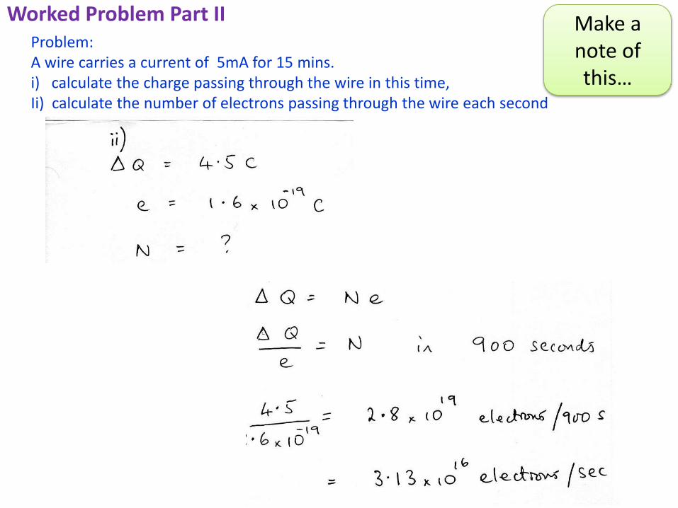
Problem: A wire carries a current of 5mA for 15 mins. i) calculate the charge passing through the wire in this time, Ii) calculate the number of electrons passing through the wire each second
Worked Problem Part II Make a note of this…

Mr Powell 2009 Index
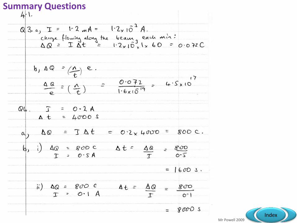
Summary Questions

Mr Powell 2009 Index
Or try this…. Q = ne So sub in Q = It It = ne It/e = n
Summary Questions
Mr Powell 2009 Index
Summary Questions

The Basics
Extension
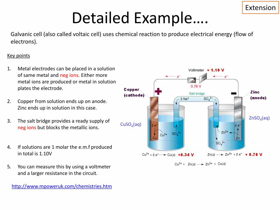
Detailed Example…. Galvanic cell (also called voltaic cell) uses chemical reaction to produce electrical energy (flow of electrons).
CuSO4(aq)
ZnSO4(aq)
Key points 1. Metal electrodes can be placed in a solution
of same metal and neg ions. Either more metal ions are produced or metal in solution plates the electrode.
2. Copper from solution ends up on anode. Zinc ends up in solution in this case.
3. The salt bridge provides a ready supply of neg ions but blocks the metallic ions.
4. If solutions are 1 molar the e.m.f produced in total is 1.10V
5. You can measure this by using a voltmeter and a larger resistance in the circuit.
http://www.mpoweruk.com/chemistries.htm
Extension

Mr Powell 2009 Index
A battery is connected across a wire. The current in the wire is 40 mA.
Starter Question….
iSlice Basic
(i) Calculate the total charge that flows past a point in the conductor in 3 minutes. (ii) Using data from the Data Sheet calculate the number of electron charge carriers passing the same point in the conductor in this time.
(iii) If 8.6 J of energy are transferred to the conductor in this time, calculate the potential difference across the conductor. (iv) Calculate the resistance of the conductor.

Mr Powell 2009 Index
4.2 Potential difference and power
Specification link-up 3.1.3: Charge, current and potential difference; Current/voltage characteristics What do we mean by potential difference? How can we calculate electrical power? How do energy transfers take place in electrical devices?
P = VI
P=E/t
V=IR
P = I2R
P=V2/R
V=W/Q
Q=I∆t E=IV∆t
E=VIt

Potential Difference (Theory)
If we think of potential difference in terms of energy transfer;
1) To bring two like charges near each other work must be done. 2) To separate two opposite charges, work must be done. 3) Whenever work gets done, energy changes form.
Monkey example; Imagine two positive spheres in space and a monkey. Imagine that a small monkey does some work on one of the positive charges. He pushes the small charge towards the big charge;
+ +
+ +
Work

This is all about a separation of charge between two points. The closer he brings it, the more potential energy it has since the two charges want to repel
When he releases the charge, work gets done on the charge. This is a change in energy;
Electrical potential energy to Kinetic energy.
If the monkey brought the charge closer to the other object, it would have more potential energy.
If he brought 2 or 3 charges instead of one, then he would have had to do more work.
Since the potential energy can change when the amount of charge you are moving changes, it is helpful to describe the potential energy per unit of charge. This is known as electrical potential or potential difference.
Potential Difference (Theory)
V = potential difference in volts, V, JC -1 W = Energy or work done in Joules, J Q = charge in coulombs, C
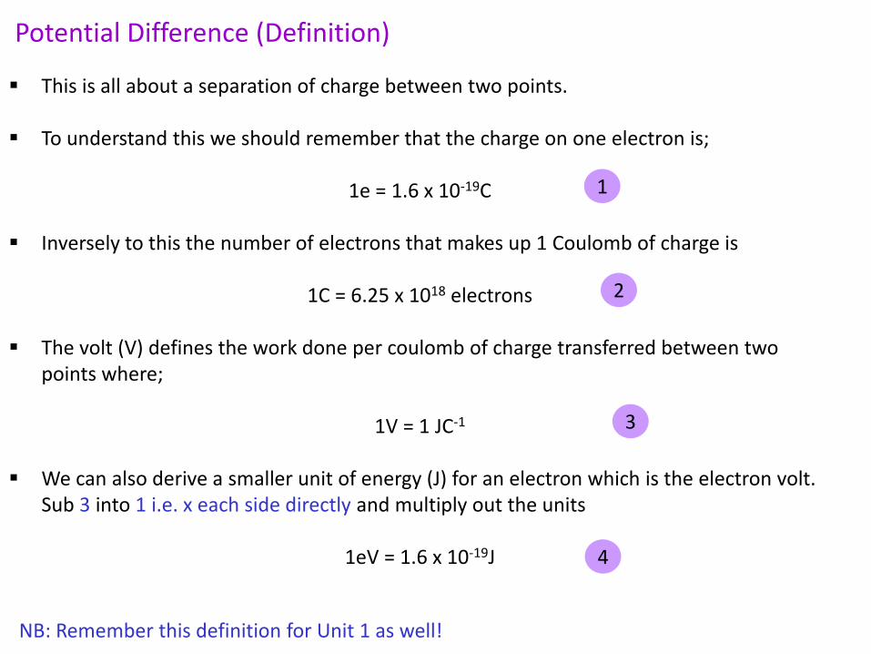
This is all about a separation of charge between two points.
To understand this we should remember that the charge on one electron is;
1e = 1.6 x 10⁻¹⁹C
Inversely to this the number of electrons that makes up 1 Coulomb of charge is
1C = 6.25 x 10¹⁸ electrons
The volt (V) defines the work done per coulomb of charge transferred between two points where;
1V = 1 JC-1
We can also derive a smaller unit of energy (J) for an electron which is the electron volt. Sub 3 into 1 i.e. x each side directly and multiply out the units
1eV = 1.6 x 10⁻¹⁹J
Potential Difference (Definition)
NB: Remember this definition for Unit 1 as well!
1
2
3
4

Mr Powell 2009 Index
Potential Difference: * is defined as the work done (or energy transfer) per unit charge
V (Volt) = W (work done, J) Q (charge, C)
B
A +
+
If 1J of work is done in moving 1 C of positive charge from A to B then the Pd is 1V
1V = 1 J / C
Summary

1.5 V 1.5 V
1.5 V
1.5 V 1.5 V 1.5 V
1.5 V V
Voltage or pd:
* is electrical pressure
* causes current to flow
* is measured in Volts (V)
with a voltmeter in parallel

Mr Powell 2009 Index
Series & Parallel PD’s

Mr Powell 2009 Index
A
In a series circuit
the voltage is shared
across components
V V
3.0 V V
V V
3 V 4
3 V 4
3 V 4
3 V 4
0.1 A
Each bulb adds more resistance to the
series circuit. The current flowing drops.
The voltage across each bulb drops
Series PD

Mr Powell 2009 Index
For a component with

Mr Powell 2009 Index
HSW - PC Energy Use Question
Energy = Power x Time Energy = 154W x 1 hour Energy = 154W x 3600s E = 154J/s x 3600s E = 554400J E = 554.4kJ
Here is an example of the energy usage of a home computer. Each internal component transfers a variable amount of energy. If you left this PC on for an hour it would transfer;
Current flow to the PC would then be… P = VI or P/V = 0.67A

Mr Powell 2009 Index
Power Delivery
When we talk about Power what we mean is “the amount of energy delivered per second”
1 Joule / 1 Second = 1 Watt
It then makes sense that the Power used by a component can be found from the product of current through and voltage across the component;
Power = Voltage x Current
P = V x I

Mr Powell 2009 Index
Example
In this circuit the Voltmeter = 4V and the Current = 1A
Power = Voltage x Current
P = V x I
P = 4V x 1A
P = 4J/C x 1C/s
P = 4J/s
P = 4W
4V
1A

Mr Powell 2009 Index
Analogy
Another way of thinking about it is saying that the current carries the energy;
4V
1A
C C C C
C C
C C C
1J
1J
1J
1J
C 1J
1J
1J
1J
1J
1J
1J
1J
1J
1J
1J
1J
1J
1J
1J
1J
1J
1J
As the Coulombs of Charge move they release their energy as heat and light (through the bulb)
C
1J
= 1 Coulomb of charge
= 1 Joule of energy
= 1 Second of time

Mr Powell 2009 Index
Analogy 2
If the voltage increases, more energy is delivered so the power increases;
5V
1A
C C C C
C C
C C C
1J
1J
1J
1J
C 1J
1J
1J
1J
1J
1J
1J
1J
1J
1J
1J
1J
1J
1J
1J
1J
1J
1J
Power = 5V x 1A = 5J/s = 5W
1J 1J 1J 1J
C
1J
= 1 Coulomb of charge
= 1 Joule of energy
= 1 Second of time

Mr Powell 2009 Index
Analogy 3
If the current increases, more energy is delivered so the power increases;
4V
2A
C C C C
C C
C C C
C 1J
1J
1J
1J
1J
1J
1J
1J
1J
1J
1J
1J
1J
1J
1J
1J
1J
1J
1J
1J
1J
1J
Power = 4V x 2A = 8J/s = 8W
C C C C
C C
C C C
C
1J
1J
1J
1J
1J
1J
1J
1J
1J
1J
1J
1J
1J
1J
1J
1J
1J
1J
1J 1J 1J
1J
C
1J
= 1 Coulomb of charge
= 1 Joule of energy
= 1 Second of time


Mr Powell 2009 Index

Mr Powell 2009 Index

Mr Powell 2009 Index
Starter/Plenary Question……
Energy = Power x Time Energy = 154W x 1 hour Energy = 154W x 1800s E = 154J/s x 1800s E = 277200J E = 277.2kJ v= 230V P = VI or P/V = 0.67A
1. If you left this PC on for 30 minutes how much energy it would transfer in that time (2 marks)
2. Current flow to the PC would then be… (2 marks)

Mr Powell 2009 Index
4.3 Resistance & Resistivity
Specification link-up 3.1.3:
Current/voltage characteristics; Resistivity
1. What causes electrical
resistance?
2. When can we use Ohm’s law?
3. What is a superconductor?
L
RA
321
21
1111
......
RRRR
RRR
T
T
Mr Powell 2009 Index
GCSE Background
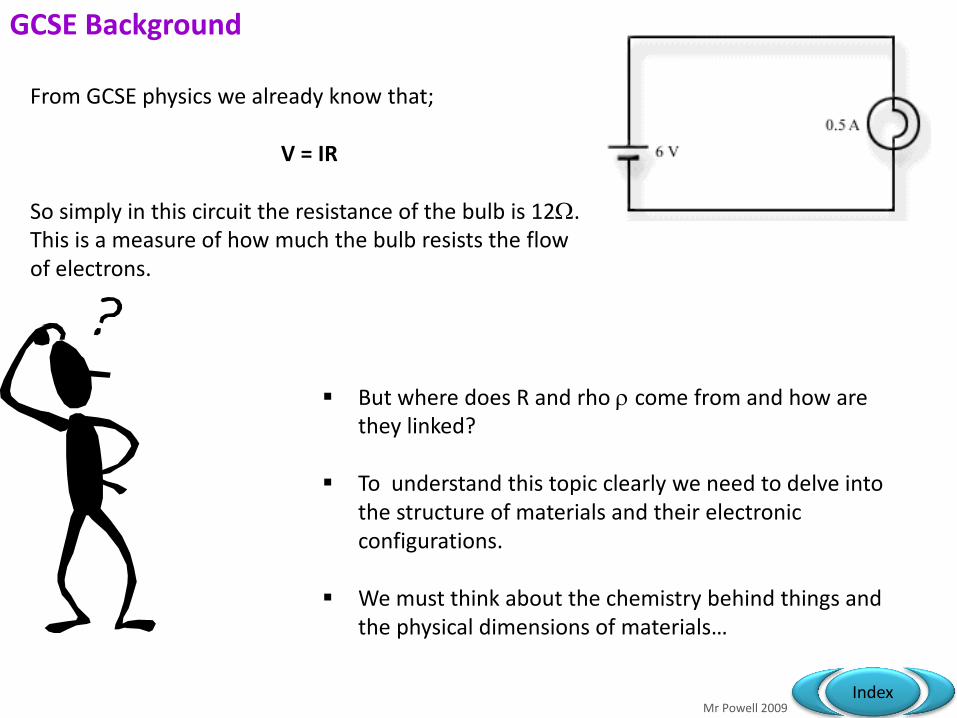
From GCSE physics we already know that;
V = IR So simply in this circuit the resistance of the bulb is 12. This is a measure of how much the bulb resists the flow of electrons.
But where does R and rho come from and how are they linked?
To understand this topic clearly we need to delve into the structure of materials and their electronic configurations.
We must think about the chemistry behind things and the physical dimensions of materials…

Mr Powell 2009 Index
http://phet.colorado.edu/simulations/index.php?cat=Physics http://www.batesville.k12.in.us/physics/PhyNet/e&m/current/ECurrent_Notes.htm
Ohm’s law: The pd across a metallic conductor is proportional to the current through it, provided the physical conditions do not change
Q. For the resistor opposite calculate: a) the resistance at this current b) the new pd when the current is 50 A
12V
2mA R ohm
a) R = V = 12 = 6000 I 2.0 x 10⁻³
b) V = I R = 50x10-6 x 6000 = 0.3 V
Resistance 1

Mr Powell 2009 Index
Measurement of resistance:
A
V
Record the pd across R for increasing values of current. ( change r to change the circuit current ()
r
The ammeter has a very low resistance ( 0.2 ohm) The voltmeter has a very high resistance ( 20,000 ohm) Why?
Pd / V
I / A
Gradient = V
I
Gradient = resistance
R
Resistance 2

Mr Powell 2009 Index
Conductors
• Metals are generally known as conductors.
• Copper electricity cables is an example and what we mean is that they conduct electrons very well.
• Metals are conductors rather than insulators as they have a unique "property".
• This "property " is that the outermost electron on the atom is relatively loosely held and can hop from atom to atom when pushed!

Mr Powell 2009 Index
Ionisation Energies
Energy in J/mol
Metal n=1 n=2 n=3 Free Electrons
Li 520 7298 11815 1
K 419 3051 4412 1
Cu 746 1958 3554 1 or 2
Zn 906 1733 3833 2
The table below shows how much energy it takes to remove a whole mole of electrons from their respective atoms.
The blue shaded regions show which are the easy ones.
It is a similar type of thing that is happening in a conductor….
NB: Don’t need to learn these energies just be aware of the idea of the stripping away!

Mr Powell 2009 Index
Modelling
So what we are talking about is an electron being ripped from its atom (home) and then moving through the structure of the other adjacent atoms in a form of drift or current.
This is an interesting motion where each electron gains some KE from the e.m.f.
Jumps to another adjacent atom losing the KE and then repeats the process over and over….
Here is a simple example of how the process might work with boron
NB: Boron was picked due to simple structure – it is not a good conductor!
e- e- e- e- e-
Mr Powell 2009 Index
Modelling II
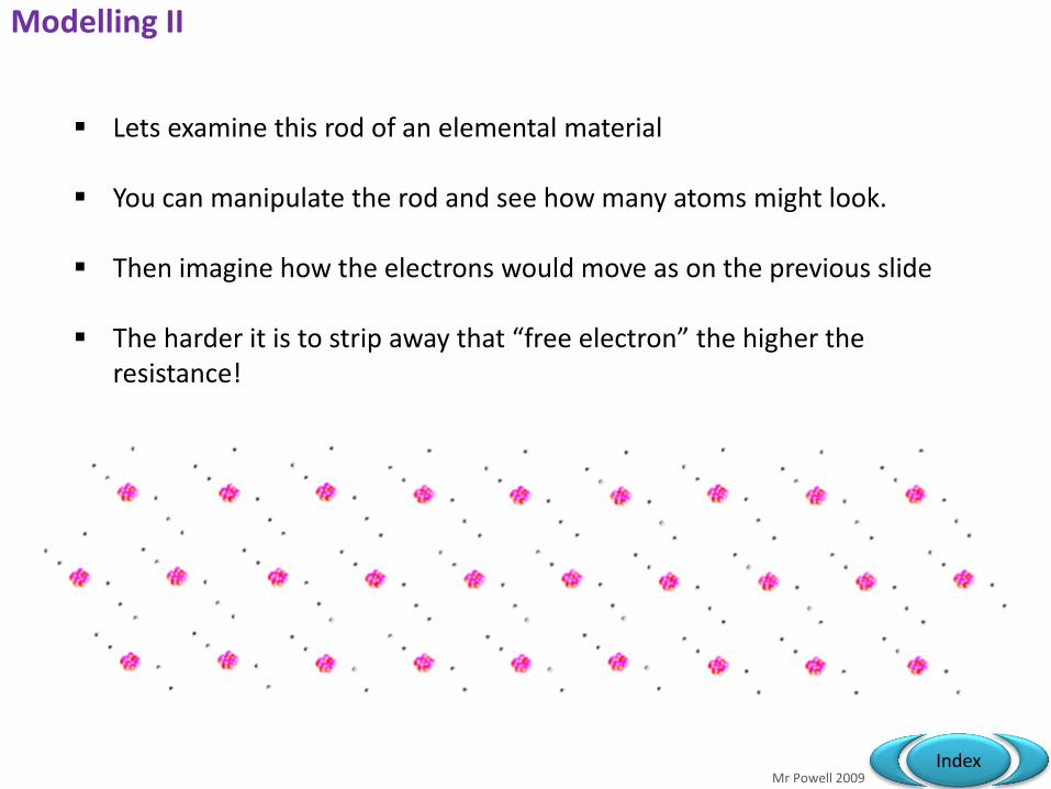
Lets examine this rod of an elemental material
You can manipulate the rod and see how many atoms might look.
Then imagine how the electrons would move as on the previous slide
The harder it is to strip away that “free electron” the higher the resistance!

Mr Powell 2009 Index
Other physical factors…
e-
e-
e-
e-
e-
At any temperature above 0K atoms will jiggle around and impede any flow of electrons
Only the electrons move as they are about 2000 times lighter than the atoms they are attached to and pick up the e.m.f
In a Copper wire with 1 x 1028 electron carriers per m3 you would have to accelerate 1 x10-26kg's of electrons.
This is quite a mass of electrons and the more you have the more push you have to use overall to get them moving!
Area and length must also effect such a problem

Mr Powell 2009 Index
Resistance or Resistivity
The formulae used to take into account how the physical factors of a wire effect resistance is chicken or egg as you can either consider using it from the R or the perspective.
A
lR
l
RA
The way I remember is resistivity = RAL and of course remember to put the L underneath to make the units correct!
NB: when A = 1m2 and l = 1m = R
Mr Powell 2009 Index
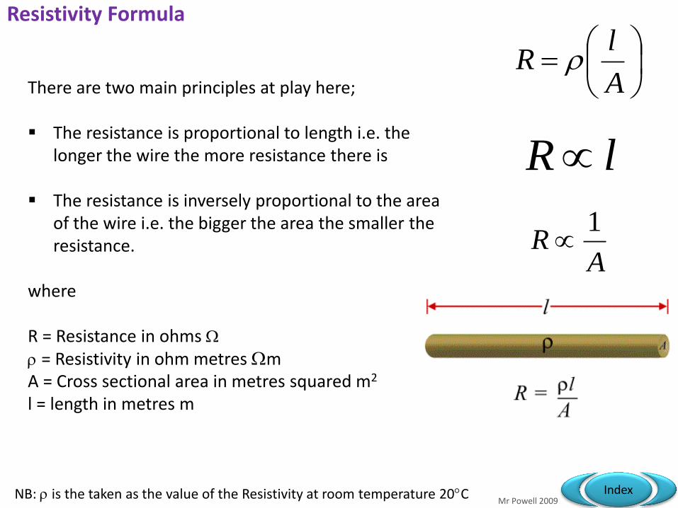
Resistivity Formula
There are two main principles at play here;
The resistance is proportional to length i.e. the longer the wire the more resistance there is
The resistance is inversely proportional to the area of the wire i.e. the bigger the area the smaller the resistance.
where R = Resistance in ohms
= Resistivity in ohm metres m A = Cross sectional area in metres squared m2 l = length in metres m
A
lR
lR
AR
1
NB: is the taken as the value of the Resistivity at room temperature 20C

Mr Powell 2009 Index
Facts and Figures
Type Material Resistivity in m
Metal
Copper 1.7 x 10⁻⁸
Gold 2.4 x 10⁻⁸
Aluminium 2.6 x 10⁻⁸
Semiconductors Germanium (pure) 0.6
Silicon (pure) 1.7 x 10³
Insulators
Glass 1.7 x 10¹²
Perspex 1.7 x 10¹³
Polyethylene 1.7 x 10¹⁴
Sulphur 1.7 x 10¹⁵
This table shows some examples you should be familiar with.
Quite simply they mean that for each substance the resistivity will be …… m (at 20C) as its constant
Mr Powell 2009 Index
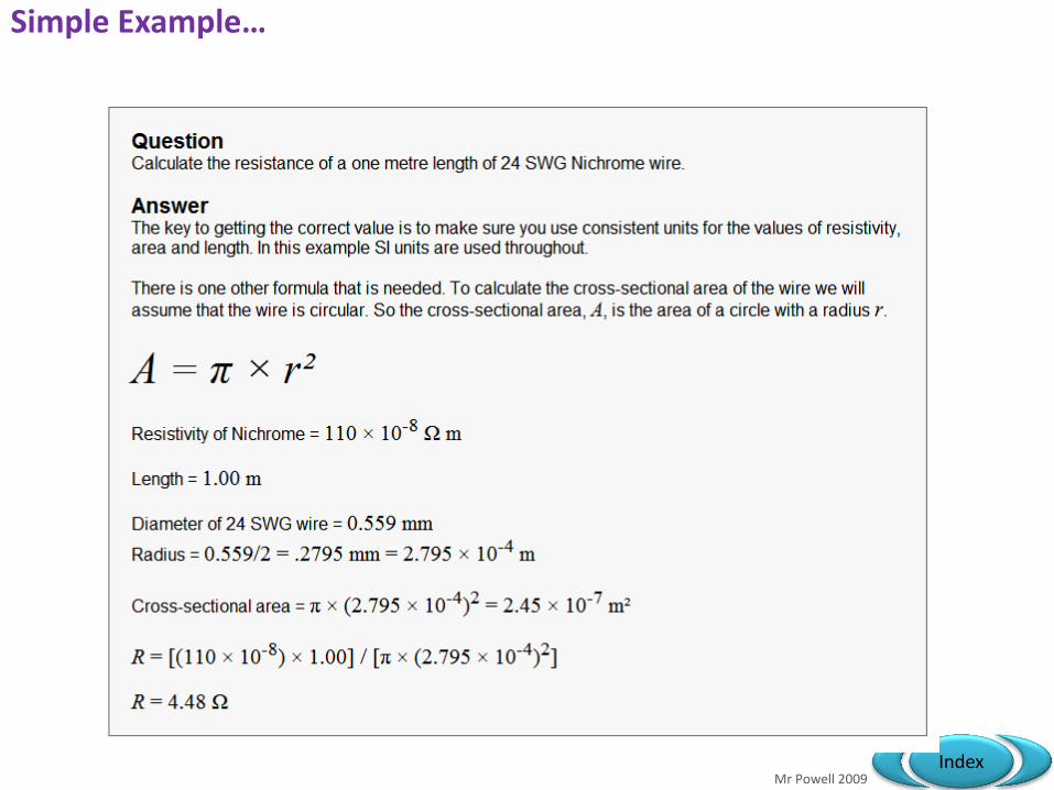
Simple Example…
Question Calculate the resistance of a one metre length of 24 SWG Nichrome wire.
Answer The key to getting the correct value is to make sure you use consistent units for the values of resistivity, area and length. In this example SI units are used throughout.
There is one other formula that is needed. To calculate the cross-sectional area of the wire we will assume that the wire is circular. So the cross-sectional area, A, is the area of a circle with a radius r. A = π × r²
Resistivity of Nichrome = 110 × 10-8 Ω m Length = 1.00 m
Diameter of 24 SWG wire = 0.559 mm Radius = 0.559/2 = .2795 mm = 2.795 × 10⁻⁴ m
Cross-sectional area = π × (2.795 × 10⁻⁴)2 = 2.45 × 10⁻⁷ m² R = [(110 × 10-8) × 1.00] / *π × (2.795 × 10⁻⁴)2]
R = 4.48 Ω

Mr Powell 2009 Index
Simple Application….
Material Resistivity in
m Thickness
cm Length
cm
Copper 1.7 x 10⁻⁸ 0.1 20
Gold 2.4 x 10⁻⁸ 0.2 10
Aluminium 2.6 x 10⁻⁸ 0.4 12
Robert Oppenheimer was making a complex atomic bomb called “Fat Man”. He needed to use a certain type of wire in his detonator circuits to connect to the primary so that the overall resistance in that part of the microcircuit was exactly 0.0008 . Then his timing would be just right to produce the maximum number of neutrons possible and thus kill as many Japanese civilians in Hiroshima as possible. He had a choice of copper, gold or aluminium wire to use in the circuit. However, each wire was of a different thickness and length.
Without cutting the wires work out which one he could use…you need to do three separate calculations using the following data;
Hint: tabulate your data or write it out for each question with conversions in full
Mr Powell 2009 Index
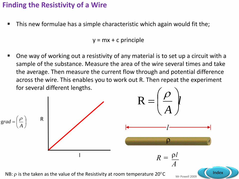
Finding the Resistivity of a Wire
Arad
g
This new formulae has a simple characteristic which again would fit the;
y = mx + c principle
One way of working out a resistivity of any material is to set up a circuit with a sample of the substance. Measure the area of the wire several times and take the average. Then measure the current flow through and potential difference across the wire. This enables you to work out R. Then repeat the experiment for several different lengths.
NB: is the taken as the value of the Resistivity at room temperature 20C
l
R
lA
R

Mr Powell 2009 Index
Resitivity?
Arad
g
Length in m Resistance in m
0.10 0.18
0.20 3.70
0.30 5.50
0.40 7.10
0.50 9.20
0.60 11.00
0.70 13.00
0.80 14.50
0.90 14.60
1.00 18.00
Use the graphing technique to find out the resistivity of a sample wire which is 0.26cm thick. What metal is the wire made from?
NB: calculated at 20C
l
R

Mr Powell 2009 Index
Looks like Gold to me!
Graph to show resistance against length
y = 18.253x
0
2
4
6
8
10
12
14
16
18
20
0 0.2 0.4 0.6 0.8 1 1.2
Length of wire in meters m
Re
sis
tan
ce
in
milli o
hm
s
1.32739x10⁻⁶m2 x 18.253x10-3 m-1 =2.42 x 10⁻⁸
m

Mr Powell 2009 Index
Electrical Resistance Data SWG - Standard Wire Gauge
Mr Powell 2009 Index
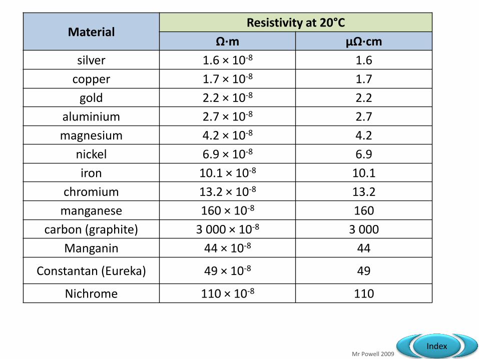
Material Resistivity at 20°C
Ω·m µΩ·cm
silver 1.6 × 10⁻⁸ 1.6
copper 1.7 × 10⁻⁸ 1.7
gold 2.2 × 10⁻⁸ 2.2
aluminium 2.7 × 10⁻⁸ 2.7
magnesium 4.2 × 10⁻⁸ 4.2
nickel 6.9 × 10⁻⁸ 6.9
iron 10.1 × 10⁻⁸ 10.1
chromium 13.2 × 10⁻⁸ 13.2
manganese 160 × 10-8 160
carbon (graphite) 3 000 × 10-8 3 000
Manganin 44 × 10-8 44
Constantan (Eureka) 49 × 10-8 49
Nichrome 110 × 10-8 110
Mr Powell 2009 Index
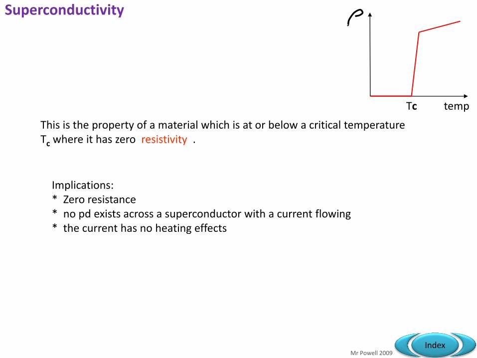
This is the property of a material which is at or below a critical temperature Tc where it has zero resistivity .
Implications: * Zero resistance * no pd exists across a superconductor with a current flowing * the current has no heating effects
temp Tc
Superconductivity

Mr Powell 2009 Index
temp Tc
Properties of a superconductor: * material losses the effect above the critical temperature Tc.
* If Tc is above 77K ( -196 C) it’s a high temperature superconductor current Tc max = 150 K - 123C
Superconductivity

Mr Powell 2009 Index

Mr Powell 2009 Index

Mr Powell 2009 Index

Mr Powell 2009 Index

Mr Powell 2009 Index
4.4 Components and their characteristics
Specification link-up 3.1.3: Circuits How does the current through a filament lamp vary with pd? What are the characteristics of a diode? What can we use a thermistor for?

ammeter
voltmeter
cell
Indicator / light source
diode
Light emitting diode
resistor
Variable resistor
thermistor
Light dependent resistor
heater
Electric motor
Many cells = a battery
No more semi circles!
of a specific value
Resistance falls as temp rises
Low resistance, connect in series
High resistance, connect in parallel
Emits light when forward biased
Resistance falls as light level rises
Conducts when forward biased
TASK: Link these symbols to names & functions….

ammeter
voltmeter
cell
Indicator / light source
diode
Light emitting diode
resistor
Variable resistor
thermistor
Light dependent resistor
heater
Electric motor
Many cells = a battery
No more semi circles!
of a specific value
Resistance falls as temp rises
Low resistance, connect in series
High resistance, connect in parallel
Emits light when forward biased
Resistance falls as light level rises
Conducts when forward biased

V
I
+ -
-
+
wire
V
I
+ -
-
+
lamp
V
I
+ -
-
+
V
I
+ -
-
+
0.6 V
thermistor diode
TASK: Draw out the axes and sketch these graphs….

V
I
+ -
-
+
wire
V
I
+ -
-
+
lamp
V
I
+ -
-
+ High temp
low temp
V
I
+ -
-
+
0.6 V
thermistor diode
Amps
Milli-amps

Mr Powell 2009 Index
Resistance and temperature
For metals: * resistance increases with temperature * positive ions vibrate more * conduction electrons movement is impeded * positive temperature coefficient
For intrinsic semiconductors: * resistance decreases with temperature * more charge carriers become available * negative temperature coefficient * much larger change in resistance /C than with metals * thermistors used as temperature sensitive component in a sensor
V
I
+ -
-
+
High temp
low temp
4.4 Components and their characteristics

Mr Powell 2009 Index
Resistance and temperature
For metals: * resistance increases with temperature * positive ions vibrate more * conduction electrons movement is impeded * positive temperature coefficient
For intrinsic semiconductors: * resistance decreases with temperature * more charge carriers become available * negative temperature coefficient * much larger change in resistance /C than with metals * thermistors used as temperature sensitive component in a sensor
V
I
+ -
-
+
High temp
low temp
V
I
+ -
-
+ High temp
low temp
4.4 Components and their characteristics

Mr Powell 2009 Index
Resistor
As the voltage increases the current also increases at the same rate.
This is what is called “ohms law”
True for resistor at a constant temperature
It is directly proportional

Mr Powell 2009 Index

Mr Powell 2009 Index
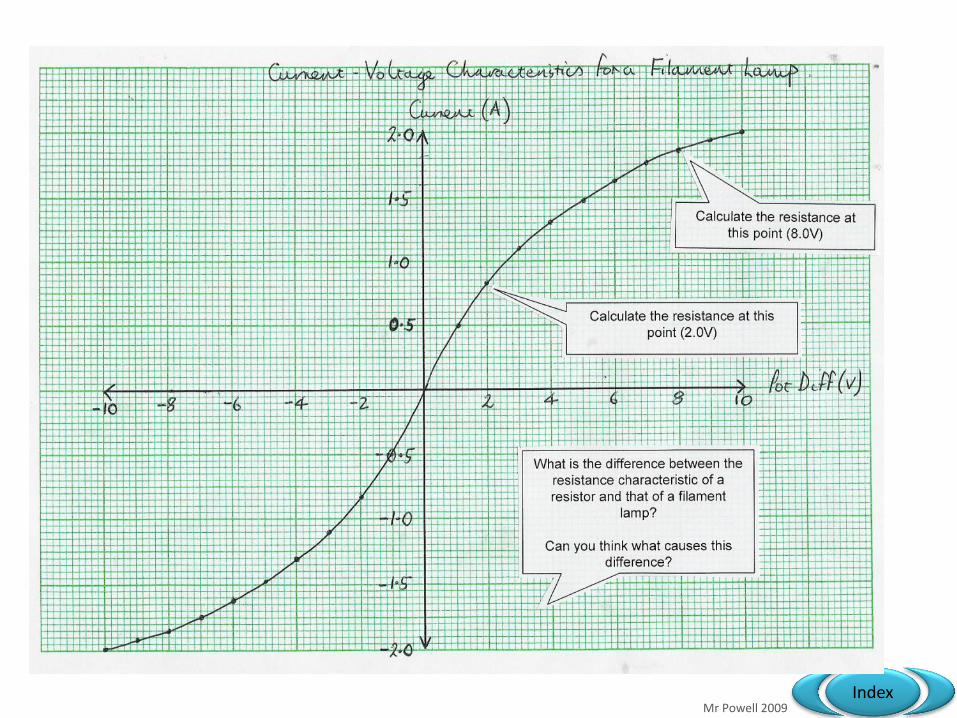
Filament Lamp / Bulb
The resistance of a filament lamp increases as the temperature of the filament increases.
i.e. the resistance changes as the temperature of the wire changes.
The gradient of the graph represents the resistance
Mr Powell 2009 Index
Mr Powell 2009 Index
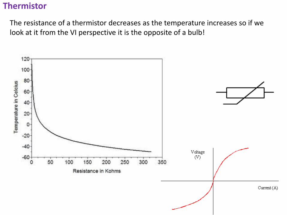
Thermistor
The resistance of a thermistor decreases as the temperature increases so if we look at it from the VI perspective it is the opposite of a bulb!

Mr Powell 2009 Index
How do they work?
The exact conduction mechanisms are not fully understood but metal oxide NTC thermistors behave like semiconductors, as shown in the decrease in resistance as temperature increases. The physical models of electrical conduction in the major NTC thermistor materials are generally based on this theory;
A model of conduction called "hopping" is relevant for some materials. It is a form of ionic conductivity where ions (oxygen ions) "hop" between point defect sites in the crystal structure.
The probability of point defects in the crystal lattice increases as temperature increases, hence the "hopping" is more likely to occur and so material resistivity decreases as temperature increases.

Mr Powell 2009 Index
Temperature Sensors?
They are inexpensive, rugged and reliable. They respond quickly to changes and are easy to manufacture in different shapes.
An example could be made from a combination of
Fe3O4 + MgCr2O4 (metallic oxides) A NTC thermistor is one in which the resistance
decreases with an increase in temperature. The circuit shows how you can use the thermistor as
a potential divider. As the temperature changes the division of voltage or energy will change. You need the 5k resistor or the voltage would be that of the cell a constant 3V.
A common use is the glass heat sensor in a car or
the temperature sensor in a conventional oven.

Mr Powell 2009 Index
LDR
The resistance of a light-dependent resistor (LDR) decreases as light intensity increases. This is a similar process to a thermistor

Mr Powell 2009 Index
Semi Conducting Diode
The current through a diode flows in one direction only. The diode has a very high resistance in the reverse direction.
Often used in transformers to change A.C to D.C. currents or computers!
Why does this happen?

Mr Powell 2009 Index
Diode – example...

Mr Powell 2009 Index
Real Data logging Information LED + 220 resistor in unit

Mr Powell 2009 Index
Diode on its own

Mr Powell 2009 Index

Mr Powell 2009 Index
Semiconductors?
Carbon, silicon and germanium (germanium, like silicon, is also a semiconductor) have a unique property in their electron structure - each has four electrons in its outer orbital.
This allows them to form nice crystals. The four electrons form perfect covalent bonds with four neighbouring atoms, creating a lattice.
In carbon, we know the crystalline form as diamond.
In silicon, the crystalline form is a silvery, metallic-looking substance. Which is a near perfect insulator.
Well on its own that is not amazing but a semi-conductor is made from a silicon lattice with an impurity which will enable it to conduct. We often refer to these types of materials as intrinsic semiconductors.

Mr Powell 2009 Index
Doping p or n?
In N-type doping, phosphorus or arsenic is added to the silicon in small quantities. Phosphorus and arsenic each have five outer electrons, so they're out of place when they get into the silicon lattice. The fifth electron has nothing to bond to, so it's free to move around. It takes only a very small quantity of the impurity to create enough free electrons to allow an electric current to flow through the silicon. N-type silicon is a good conductor. Electrons have a negative charge, hence the name N-type. In P-type doping, boron or gallium is the doping agent. Boron and gallium each have only three outer electrons. When mixed into the silicon lattice, they form "holes" in the lattice where a silicon electron has nothing to bond to. The absence of an electron creates the effect of a positive charge, hence the name P-type. Holes can conduct current. A hole happily accepts an electron from a neighbour, moving the hole over a space. P-type silicon is a good conductor.
p-type
n-type

Mr Powell 2009 Index
PN junctions?
N-type and P-type silicon are not that amazing by themselves; but when you put them together, you get some very interesting behaviour at the junction. That's what happens in a diode.
The place where they meet in the diagram forms what is called a depletion zone.
Where free electrons have filled positive “holes” to form an area where there are no free charge carriers.
P N P N P N

Mr Powell 2009 Index
PN junctions - behaviour to applied pd
V< 0.7V V> 0.7V
This typically takes 0.7V to overcome and bridge the gap and make it conduct!
If we reverse the flow then the gap gets larger and does not conduct (up to 30V)
V< 0V V<< 0V
P N P N P N
P N P N P N
Mr Powell 2009 Index
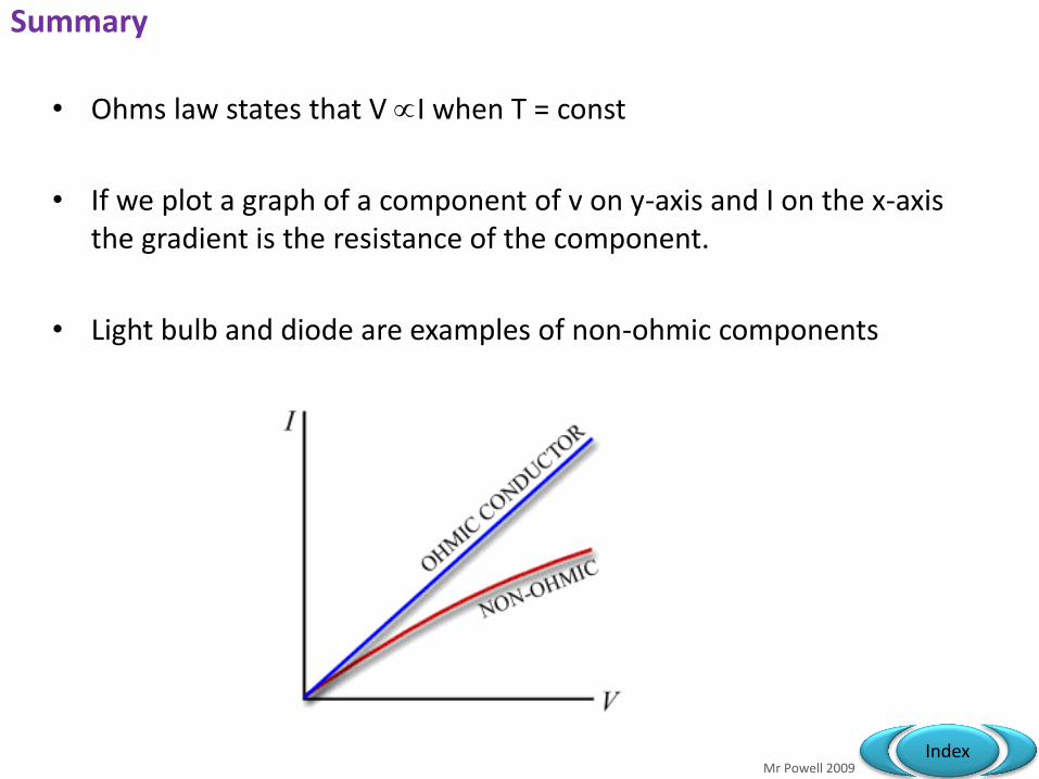
Summary
• Ohms law states that V I when T = const
• If we plot a graph of a component of v on y-axis and I on the x-axis the gradient is the resistance of the component.
• Light bulb and diode are examples of non-ohmic components
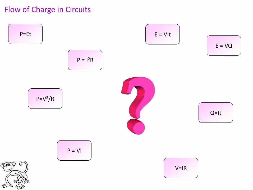
Flow of Charge in Circuits
P = VI
P=Et
V=IR
P = I2R
P=V2/R
Q=It
E = VIt
E = VQ

Ideas for Circuits….
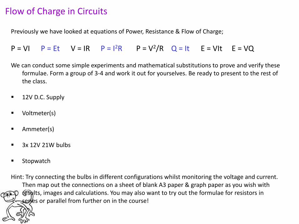
Flow of Charge in Circuits
Previously we have looked at equations of Power, Resistance & Flow of Charge;
P = VI P = Et V = IR P = I2R P = V2/R Q = It E = VIt E = VQ We can conduct some simple experiments and mathematical substitutions to prove and verify these
formulae. Form a group of 3-4 and work it out for yourselves. Be ready to present to the rest of the class.
12V D.C. Supply
Voltmeter(s)
Ammeter(s)
3x 12V 21W bulbs
Stopwatch
Hint: Try connecting the bulbs in different configurations whilst monitoring the voltage and current.
Then map out the connections on a sheet of blank A3 paper & graph paper as you wish with results, images and calculations. You may also want to try out the formulae for resistors in series or parallel from further on in the course!

Mr Powell 2009 Index
Mr Powell 2009 Index

Mr Powell 2009 Index

Mr Powell 2009 Index