
as Entropy Sources - Simple searchliu.diva-portal.org/smash/get/diva2:826555/FULLTEXT01.pdf ·...
69
Institutionen för systemteknik Department of Electrical Engineering Examensarbete Implementing and Testing Self-Timed Rings on a FPGA as Entropy Sources Examensarbete utfört i Datorteknik vid Tekniska högskolan vid Linköpings universitet av Marcus Einar LiTH-ISY-EX--15/4845--SE Linköping 2015 Department of Electrical Engineering Linköpings tekniska högskola Linköpings universitet Linköpings universitet SE-581 83 Linköping, Sweden 581 83 Linköping
Transcript of as Entropy Sources - Simple searchliu.diva-portal.org/smash/get/diva2:826555/FULLTEXT01.pdf ·...

Institutionen för systemteknikDepartment of Electrical Engineering
Examensarbete
Implementing and Testing Self-Timed Rings on a FPGAas Entropy Sources
Examensarbete utfört i Datorteknikvid Tekniska högskolan vid Linköpings universitet
av
Marcus Einar
LiTH-ISY-EX--15/4845--SE
Linköping 2015
Department of Electrical Engineering Linköpings tekniska högskolaLinköpings universitet Linköpings universitetSE-581 83 Linköping, Sweden 581 83 Linköping


Implementing and Testing Self-Timed Rings on a FPGAas Entropy Sources
Examensarbete utfört i Datorteknikvid Tekniska högskolan vid Linköpings universitet
av
Marcus Einar
LiTH-ISY-EX--15/4845--SE
Handledare: Jonathan Jogenforsisy, Linköpings universitet
Johan HedströmSectra Communications
Examinator: Jan-Åke Larssonisy, Linköpings universitet
Linköping, 25 juni 2015


Avdelning, InstitutionDivision, Department
Avdelningen för SystemteknikDepartment of Electrical EngineeringSE-581 83 Linköping
DatumDate
2015-06-25
SpråkLanguage
� Svenska/Swedish
� Engelska/English
�
�
RapporttypReport category
� Licentiatavhandling
� Examensarbete
� C-uppsats
� D-uppsats
� Övrig rapport
�
�
URL för elektronisk version
http://urn.kb.se/resolve?urn=urn:nbn:se:liu:diva-XXXXX
ISBN
—
ISRN
LiTH-ISY-EX--15/4845--SE
Serietitel och serienummerTitle of series, numbering
ISSN
—
TitelTitle
Implementation och Testning av Self-Timed Rings på en FPGA som Entropikällor
Implementing and Testing Self-Timed Rings on a FPGA as Entropy Sources
FörfattareAuthor
Marcus Einar
SammanfattningAbstract
Random number generators are basic building blocks of modern cryptographic systems.Usually pseudo random number generators, carefully constructed deterministic algorithmsthat generate seemingly random numbers, are used. These are built upon foundations ofthorough mathematical analysis and have been subjected to stringent testing to make surethat they can produce pseudo random sequences at a high bit-rate with good statistical prop-erties.
A pseudo random number generator must be initiated with a starting value. Since they aredeterministic, the same starting value used twice on the same pseudo random number gener-ator will produce the same seemingly random sequence. Therefore it is of utmost importancethat the starting value contains enough entropy so that the output cannot be predicted or re-produced in an attack. To generate a high entropy starting value, a true random numbergenerator that uses sampling of some physical non-deterministic phenomenon to generateentropy, can be used. These are generally slower than their pseudo random counterparts butin turn need not generate the same amount of random values.
In field programmable gate arrays (FPGA), generating random numbers is not trivial sincethey are built upon digital logic. A popular technique to generate entropy within a FPGA isto sample jittery clock signals. A quite recent technique proposed to create a robust clocksignals, that contains such jitter, is to use self-timed ring oscillators. These are structures inwhich several events can propagate freely at an evenly spaced phase distribution.
In this thesis self-timed rings of six different lengths is implemented on a specific FPGAhardware. The different implementations are tested with the TestU01 test suite. The resultsshow that two of the implementations have a good oscillatory behaviour that is well suitedfor use as random number generators. Others exhibit unexpected behaviours that are notsuited to be used in a random number generator. Two of the implemented random generatorspassed all tests in the TestU01 batteries Alphabit and BlockAlphabit. One of the generatorswas deemed not fit for use in a random number generator after failing all of the tests. Thelast three were not subjected to any tests since they did not behave as expected.
NyckelordKeywords Self-Timed Rings, Entropi, FPGA


Abstract
Random number generators are basic building blocks of modern cryptographicsystems. Usually pseudo random number generators, carefully constructed deter-ministic algorithms that generate seemingly random numbers, are used. Theseare built upon foundations of thorough mathematical analysis and have beensubjected to stringent testing to make sure that they can produce pseudo randomsequences at a high bit-rate with good statistical properties.
A pseudo random number generator must be initiated with a starting value. Sincethey are deterministic, the same starting value used twice on the same pseudorandom number generator will produce the same seemingly random sequence.Therefore it is of utmost importance that the starting value contains enough en-tropy so that the output cannot be predicted or reproduced in an attack. To gen-erate a high entropy starting value, a true random number generator that usessampling of some physical non-deterministic phenomenon to generate entropy,can be used. These are generally slower than their pseudo random counterpartsbut in turn need not generate the same amount of random values.
In field programmable gate arrays (FPGA), generating random numbers is nottrivial since they are built upon digital logic. A popular technique to generateentropy within a FPGA is to sample jittery clock signals. A quite recent techniqueproposed to create a robust clock signals, that contains such jitter, is to use self-timed ring oscillators. These are structures in which several events can propagatefreely at an evenly spaced phase distribution.
In this thesis self-timed rings of six different lengths is implemented on a spe-cific FPGA hardware. The different implementations are tested with the TestU01test suite. The results show that two of the implementations have a good oscilla-tory behaviour that is well suited for use as random number generators. Othersexhibit unexpected behaviours that are not suited to be used in a random num-ber generator. Two of the implemented random generators passed all tests inthe TestU01 batteries Alphabit and BlockAlphabit. One of the generators wasdeemed not fit for use in a random number generator after failing all of the tests.The last three were not subjected to any tests since they did not behave as ex-pected.
iii


Acknowledgments
During the work of this thesis I have gained a lot of new knowledge and experi-ence and it would not have been possible if it were not for the help and support ihave had along the way.
I would like to thank all the employees at SECTRA communications who hashelped me and shared their experience. Especially my supervisor Johan Hedströmwho has given me a lot of his time to discuss my problems and thoughts through-out the work.
I would also like to thank my examiner Jan-Åke Larsson and my supervisorJonatan Jogenfors at the department of electrical engineering.
Many, many thanks goes to my girlfriend, my family and my friends who hassupported me throughout the course of my education. Without you I would nothave made it this far.
A special thought goes out to my mother whom I wish could have seen me grad-uate. She always supported me and helped me, in so many ways, become who Iam today.
Linköping, June 2015Marcus Einar
v


Contents
Notation ix
1 Introduction 11.1 History of random number generation . . . . . . . . . . . . . . . . 11.2 Background . . . . . . . . . . . . . . . . . . . . . . . . . . . . . . . 21.3 Purpose . . . . . . . . . . . . . . . . . . . . . . . . . . . . . . . . . . 21.4 Method . . . . . . . . . . . . . . . . . . . . . . . . . . . . . . . . . . 31.5 Delimitations . . . . . . . . . . . . . . . . . . . . . . . . . . . . . . . 31.6 Structure . . . . . . . . . . . . . . . . . . . . . . . . . . . . . . . . . 4
2 Random number generators 52.1 Randomness . . . . . . . . . . . . . . . . . . . . . . . . . . . . . . . 52.2 Entropy . . . . . . . . . . . . . . . . . . . . . . . . . . . . . . . . . . 62.3 Pseudo Random Number Generators . . . . . . . . . . . . . . . . . 72.4 True Random Number Generators . . . . . . . . . . . . . . . . . . . 72.5 Jittery clock true random number generators . . . . . . . . . . . . 7
2.5.1 Jitter . . . . . . . . . . . . . . . . . . . . . . . . . . . . . . . 72.5.2 Sampling jittery signals for entropy . . . . . . . . . . . . . . 8
3 Oscillator based true random number generators 113.1 Inverter Ring Oscillators . . . . . . . . . . . . . . . . . . . . . . . . 113.2 Self-Timed Rings . . . . . . . . . . . . . . . . . . . . . . . . . . . . . 12
3.2.1 Muller-gate . . . . . . . . . . . . . . . . . . . . . . . . . . . . 123.2.2 Structure . . . . . . . . . . . . . . . . . . . . . . . . . . . . . 133.2.3 Behaviour . . . . . . . . . . . . . . . . . . . . . . . . . . . . 133.2.4 Entropy extraction . . . . . . . . . . . . . . . . . . . . . . . 16
4 Testing the randomness 194.1 Random number testing . . . . . . . . . . . . . . . . . . . . . . . . 194.2 Batteries and tests used in this studie . . . . . . . . . . . . . . . . . 19
4.2.1 Framework: TestU01 . . . . . . . . . . . . . . . . . . . . . . 194.2.2 Batteries . . . . . . . . . . . . . . . . . . . . . . . . . . . . . 20
vii

viii Contents
5 Implementation 215.1 Configurations . . . . . . . . . . . . . . . . . . . . . . . . . . . . . . 215.2 Logic design . . . . . . . . . . . . . . . . . . . . . . . . . . . . . . . 21
5.2.1 Muller-gate . . . . . . . . . . . . . . . . . . . . . . . . . . . . 215.2.2 Gate placement . . . . . . . . . . . . . . . . . . . . . . . . . 225.2.3 Synchronization chain . . . . . . . . . . . . . . . . . . . . . 22
5.3 Fabric layout . . . . . . . . . . . . . . . . . . . . . . . . . . . . . . . 235.3.1 Combinatorial loops . . . . . . . . . . . . . . . . . . . . . . 235.3.2 Floor plan . . . . . . . . . . . . . . . . . . . . . . . . . . . . 23
6 Results 256.1 Method . . . . . . . . . . . . . . . . . . . . . . . . . . . . . . . . . . 25
6.1.1 Method of sampling randomness . . . . . . . . . . . . . . . 256.1.2 Method of measuring period time and jitter . . . . . . . . . 25
6.2 Measurements . . . . . . . . . . . . . . . . . . . . . . . . . . . . . . 266.2.1 Unexpected behaviour . . . . . . . . . . . . . . . . . . . . . 266.2.2 Stable oscillation . . . . . . . . . . . . . . . . . . . . . . . . 286.2.3 Oscillation period . . . . . . . . . . . . . . . . . . . . . . . . 30
6.3 Test results . . . . . . . . . . . . . . . . . . . . . . . . . . . . . . . . 306.3.1 Alphabit battery test results . . . . . . . . . . . . . . . . . . 306.3.2 BlockAlphabit battery . . . . . . . . . . . . . . . . . . . . . 31
7 Conclusion 357.1 Self-timed ring as random number generator . . . . . . . . . . . . 357.2 Implementation . . . . . . . . . . . . . . . . . . . . . . . . . . . . . 367.3 Testing . . . . . . . . . . . . . . . . . . . . . . . . . . . . . . . . . . 367.4 Future work . . . . . . . . . . . . . . . . . . . . . . . . . . . . . . . 37
A Test result summaries 41A.1 Alphabit battery . . . . . . . . . . . . . . . . . . . . . . . . . . . . . 41
A.1.1 STRNG length 255 . . . . . . . . . . . . . . . . . . . . . . . 41A.1.2 STRNG length 511 . . . . . . . . . . . . . . . . . . . . . . . 41A.1.3 STRNG length 1535 . . . . . . . . . . . . . . . . . . . . . . . 42
A.2 BlockAlphabit battery . . . . . . . . . . . . . . . . . . . . . . . . . . 42A.2.1 STRNG length 255 . . . . . . . . . . . . . . . . . . . . . . . 42A.2.2 STRNG length 511 . . . . . . . . . . . . . . . . . . . . . . . 44A.2.3 STRNG length 1535 . . . . . . . . . . . . . . . . . . . . . . . 45
Bibliography 51
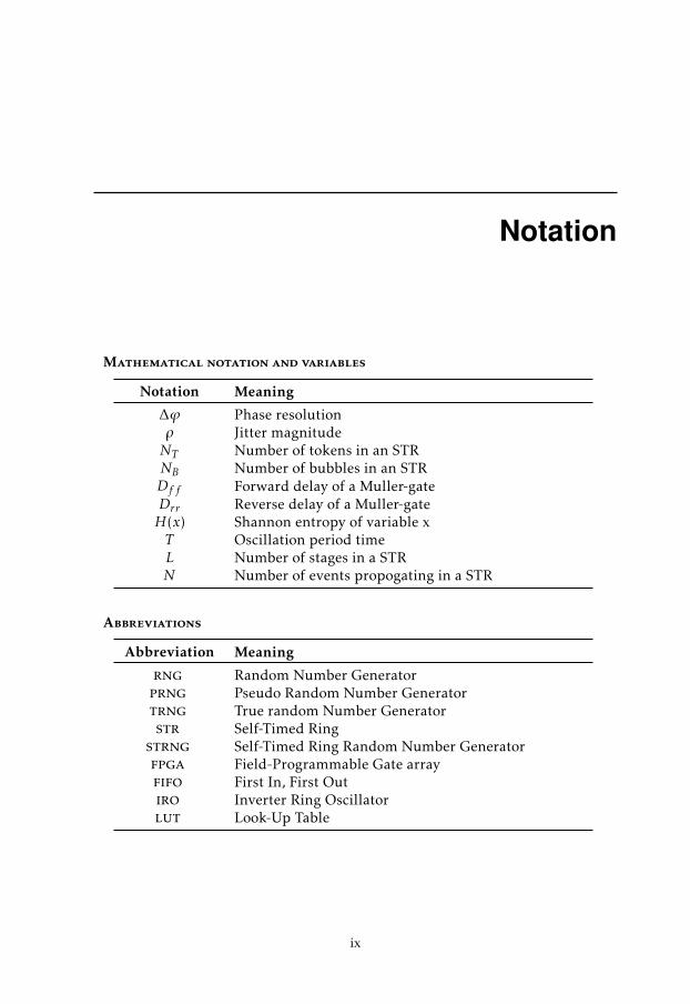
Notation
Mathematical notation and variables
Notation Meaning
∆ϕ Phase resolutionρ Jitter magnitudeNT Number of tokens in an STRNB Number of bubbles in an STRDf f Forward delay of a Muller-gateDrr Reverse delay of a Muller-gateH(x) Shannon entropy of variable xT Oscillation period timeL Number of stages in a STRN Number of events propogating in a STR
Abbreviations
Abbreviation Meaning
rng Random Number Generatorprng Pseudo Random Number Generatortrng True random Number Generatorstr Self-Timed Ringstrng Self-Timed Ring Random Number Generatorfpga Field-Programmable Gate arrayfifo First In, First Outiro Inverter Ring Oscillatorlut Look-Up Table
ix


1Introduction
This chapter contains a short historical background on random number genera-tion, the purpose of this project, the methods used in this thesis, the delimitationsof the project and the structure of this report.
1.1 History of random number generation
The concept of randomness has been used in different contexts for ages. An-cient civilizations threw bones to determine fate and foresee the future, lots weredrawn to settle disputes over distribution of land, dice have been used in gamesand decision making as early as circa 2750 B.C [7]. Whether the belief was thatluck, divine will or something else governed the outcome, all of the mentionedtypes of randomness had a common purpose: to eliminate the possibility of hu-man manipulation when trying to produce an unpredictable outcome.
The uses of random numbers has expanded since. Examples that are relevanttoday are simulations of natural phenomena, sampling data, solving numericalproblems, testing software design and, most relevant for this thesis, generationof cryptographic keys. For such scientific applications the classical ways of gen-erating randomness were too slow.
In 1927 L. H. C. Tippett published "Random Sampling Numbers", a table of morethan 40.000 "random" numbers taken from census reports. Random number ta-bles were developed even further. Machines where used to mechanically generatelarger amount of numbers. These tables were used as a fast way to get randomnumbers.
When computers came into use, memory size and input time were factors that
1
2 1 Introduction
made random number tables impractical to use. Ever since, methods for gener-ating random numbers within the systems have been sought after. Today thereexists a multitude of alternatives for generating random numbers for use in com-puter science.
1.2 Background
Random number generators (RNG ) are one of the basic building blocks of mod-ern cryptographic systems. Examples of usages for the random numbers gener-ated are cryptographic keys, authentication challenges, one-time-pads and saltfor protecting database hashes of passwords.
There are two main categories of RNGs. Pseudo random number generators(PRNG ) produce numbers that seem random from algorithms. PRNGs usuallyhave a high output bit rate and the statistical properties of the generated dataoften has good statistical properties. Since algorithms are inheritable determin-istic, the output can be reproduced if the initial value, also called seed, and thealgorithm is known. Usually only the key is secret and chosen at random. Truerandom number generators (TRNG ) utilizes physical phenomena to generate ran-dom numbers. The bit-rate and statistical properties of the output are often lowerthan that of PRNGs. However the values are more unpredictable and importantly,they can not be reproduced. TRNGs are usually used to seed PRNGs.
Field-programmable gate arrays FPGAs are programmable digital integrated cir-cuits that can be used to implement cryptographic systems. There are no naturalsources of entropy within such circuits which makes it non-trivial to seed a PRNGimplementation. One solution is to use an external source of entropy. Anotherway is to implement some digital structure that uses the properties of the internalcomponents to generate randomness. A popular technique is using clock timingjitter as a source of entropy.
Cherkaoui et al. has proposed and analysed self-timed rings (STR ) as a jitteryclock that can be used to generate random numbers at a high bit rate [8][9][10][11]. They showed that STR based RNGs can be used as an alternative tothe popular inverter ring oscillator (IRO )since it has shown to be more robustagainst voltage variations. A model for evaluating a lower bound of entropy wasalso shown.
1.3 Purpose
FPGAs generally do not have any built in way to generate random data. Samplingjittery clocks is a common technique for doing so. Relatively recently, self-timedrings has been proposed to work as a way of generating jittery clock signals, butalso robust, clock signals to be used in such random number generators.
The work of this thesis was requested by SECTRA Communications, a companythat provides secure communication solutions. All secure communication chan-
1.4 Method 3
nels are protected by cryptographic systems and all such systems need randomlygenerated numbers. The purpose of this thesis is to create an implementation ofa self-timed ring random number generator on a specific FPGA and to test howwell it works.
1.4 Method
Self-timed ring random number generators (STRNG ) have been successfully im-plemented by the authors of [10] [8] [9] [11]. Both the theory and the performancehave been well documented and this thesis does not seek to prove the concept ofa self timed ring based random number generator. The focus lies on studying thecore concepts of the self-timed ring structure and implementing it on a specifichardware assigned by SECTRA.
The implementation, which builds upon the theoretical study done on self-timedrings, is tested using the test suite TestU01 which contains batteries for testingthe statistical properties of a random number generator. The choice of test suiteis based upon the analysis of test suites done by the Jakobsson in 2014 in [17],where several test suites were compared and tested. TestU01 is recommended asa state of the art RNG test suite that allows testing of as large random values asneeded.
1.5 Delimitations
The focus of this thesis is to describe the theory of STRNGs, implementing aSTRNG on a specific FPGA followed by testing it. Different lengths of the ringsare tested to see if the lengths has any impact on the tests carried out on sam-pled data. The tests are carried out with the test suite TestU01, which seemsbest suited for testing a STRNG, based on the analysis of test suites in[17]. TheAlphabit and BlockAlphabit batteries are the only ones in the suite created specif-ically to test hardware based random number generators and therefore the onlyones used during the testing.
Some important aspects of implementing a TRNG is omitted in this thesis:
Data sequences from RNGs that are based on a physical phenomena are oftensubject to bias in the data. Post processing methods are the usually the solutionto these problems but this thesis will not cover these methods.
Another problem which is not considered in this report is that a hardware basedrandom number generator might stop working correctly during usage. To de-tect flaws, live-tests can be implemented to assure that an implementation keepsworking as intended.
Trying to actively attacking the RNG can be a method of assuring robustness ofthe implementation. This area will not be covered in thesis.

4 1 Introduction
The specific FPGA used to implement the STRNG cannot be disclosed due toconfidentiality reasons.
1.6 Structure
Chapter 2 discusses randomness, entropy and random number generators in gen-eral. It also explains the theory behind sampling jittery clocks as a mean to har-vest entropy.
In chapter 3 oscillator based TRNGs are described as well as the theory behindSTRNGs.
Chapter 4 mentions the tests used to test the implementation used in this thesiswhich is described in Chapter 5.
Chapter 6 contains the results and conclusions are drawn in chapter 7.

2Random number generators
This chapter discusses the concepts of randomness and entropy as the unit formeasuring unpredictability. It also discusses the difference between pseudo- andtrue random number generators. The theoretical model for the self-timed ringrandom number generator is also described.
2.1 Randomness
Before discussing random number generators it may be good to look at some defi-nitions of randomness. Here follows a few definitions from different dictionaries:
Random, adj.Oxford Dictionaries[4] - Made, done, or happening without method or consciousdecision
Camebridge Dictionaries[2] - Happening, done, or chosen by chance rather thanaccording to a plan
The American Heritage Dictionary[1] - Having no specific pattern, purpose, orobjective
Dictionary.com[3] - Proceeding, made, or occurring without definite aim, reason,or pattern
These definitions describes the core aspects of randomness. There is no pattern,no choice and no reason. In other words, a process of which the outcome cannotbe predicted or controlled. These definitions are neither scientific nor mathemat-ical, but they provide a grasp of what is meant when speaking of randomness.In fact, if an event is random depends on the scope and the environment. In
5

6 2 Random number generators
fact, dice rolls, coin tosses and the break at the beginning of a billiard game areexamples of processes that might seem random. However, the outcome of allthe mentioned physical processes could be predicted or perhaps even controlledgiven enough information on their initial state. This illustrates a problem withdefining what randomness really is. One might argue that randomness is basedon the ignorance of how a system, that produces random values, really works.
2.2 Entropy
The unit for measuring randomness is called entropy. Entropy is the measure-ment of how much uncertainty there is about the value of a random variable.Before formally defining entropy it might be good to look at an example first.This example is inspired by [14]:
Example 2.1Consider the output of a RNG consisting of 32 bits where every bit is completelyrandom. The output value then has 32 bits of entropy.
Example 2.1 shows that if every bit is completely random the entropy measuredin bits is the same as the length of the random variable. But what if the entireoutput was not completely random? This is illustrated in another example:
Example 2.2Consider a RNG where each byte of a 32-bit output only had two possible values,say all zeroes or ones for example. The second RNGs output would now have only4 bits of entropy.
Example 2.2 illustrates that entropy is not about the length of the random se-quence, but how much uncertainty there is about the next value. In this case it isknown that all the first eight bits are all the same. Therefore the entropy of thefirst byte is equal to one bit.
An informal way of describing what it means that a value has n-bits entropy, isif someone would try to guess the value, there would be a probability of 1/2n
that the guess was right. The entropy would change if more was known aboutthe value. For example if the distribution of ones and zeroes were known, theamount of possible values could be reduced, and in turn the uncertainty of thebits.
A more formal and perhaps the most common definition is the Shannon entropy[12][14].
Definition 2.1 (Shannon entropy). The Shannon entropy for a random variableX where P (X = x) is the probability mass function.
H(X) = −∑x
P (X = x) logb P (X = x) (2.1)

2.3 Pseudo Random Number Generators 7
The result of H(X) is the entropy of the variable X in bits, where P(X=x) is theprobability of X taking the value x. This is then summarized over all possiblevalues of X.
When b = 2 the entropy is measured in bits. From this we can define the binaryentropy as:
Definition 2.2 (Binary entropy). For any random variable X with the probabil-
ity mass function P (X = x) where x = {0, 1} such that: P (X = x) =
p if x = 11 − p if x = 0
The binary entropy measured in bits is then defined as:
H(p) = −p log p − (1 − p) log (1 − p) (2.2)
2.3 Pseudo Random Number Generators
PRNGs algorithmically generate seemingly random numbers from an initiationvalue called a seed. Since algorithms are naturally deterministic, anyone knowingthe exact algorithm and seed can reproduce the same pseudo random sequence.RNGs of this type are usually both fast and have good statistical properties in thesense that they pass most statistical tests.
2.4 True Random Number Generators
A TRNG utilizes some non-deterministic physical phenomenon to produce ran-domness. STRNG utilizes phase jitter in digital signals as a source of entropy.Other examples of TRNGs are thermal noise, quantum mechanics, atmosphericnoise and nuclear decay. TRNGs are usually slower than PRNGs and also haveworse statistical properties, but they are in turn more unpredictable. This makesthem suitable for seeding PRNGs since an unpredictable seed gives good qualitypseudo randomness.
2.5 Jittery clock true random number generators
Clock jitter can be used as a source of randomness. This section defines jitter anddescribes how entropy can be gained from sampling jittery signals.
2.5.1 Jitter
Jitter is the difference in time between the ideal signal would appear appear intime and when it appears in reality. An ideal clock would have a fixed frequencywhere each clock cycle would be exactly the same length. In reality, this is not thecase. Jitter is mostly an unwanted phenomenon as it can cause timing error in syn-chronous digital systems[6]. All jitter can be divided into two components[15],

8 2 Random number generators
Figure 2.1: A clock signal with jitter boundaries marked in gray.
deterministic and Gaussian (random) jitter. Self-timed rings utilizes the latter togather entropy.
Deterministic Jitter
Deterministic jitter is both predictable and reproducible. These are propertiesthat are unwanted and threatening to RNGs since they could provide a way toattack a cryptographic system implementing it. If the deterministic portion ofthe total jitter is much greater than the Gaussian jitter it might make it morechallenging to measure and determine the size of the Gaussian jitter [11].
Deterministic jitter comes from global sources that produce noise. Examples ofthese sources are: temperature variations and power supply voltage. Both ofthese variables are rather easy to manipulate for an attacker.
Gaussian Jitter
Gaussian jitter is a completely random variation in time that comes from thermalwhite noise generated locally inside electrical components. This kind of jitteris unavoidable and it is not affected by any external noise sources nor is it pre-dictable or reproducible. The random variable produced from Gaussian jitterhas a normal distribution N (T , σ2), where σ is the standard deviation in timefrom the ideal time T [9].
2.5.2 Sampling jittery signals for entropy
A jittery signal can be used to harvest entropy. Assume that the signal is sampledat a time t and that the jittery signal ideally has a positive edge at time T .
Jittery signal
Sample clock
t
Figure 2.2: Sampling of jittery signal at time t.
Assume that the random variable X is the actual time of the edge in time. Theprobability that sampled bit at time t is 0 can be calculated with equation 2.3,
P (X < t) = Φ(t − Tσ
) (2.3)

2.5 Jittery clock true random number generators 9
where Φ is the cumulative distribution function defined by equation 2.3.
Φ(x) =
x∫−∞
et2/2dt (2.4)


3Oscillator based true random number
generators
Sampling jitter from clock signals is a common technique used in many TRNGsto harvest entropy. Classically IROs has been a popular way of doing so. STRshas been compared to IROs by the authors of [10] where it is proposed as a morerobust way of generating jittery clocks that are less susceptible to global deter-ministic interferences.
Section 3.1 describes the basic structure of IROs as a way to describe the mostsimple form of ring based oscillators. Section 3.2 describes STRs structure andbehaviour.
3.1 Inverter Ring Oscillators
The simplest form of ring oscillator is the IRO. An IRO can be implemented byserially connecting an uneven number of inverters to form a loop as illustrated infigur 3.1.
Figure 3.1: Inverter Ring Oscillator with an uneven number of inverters con-nected in series to form a loop.
A signal measured at the output of any inverter will oscillate. Since the digi-tal signal eventually will propagate around the uneven number of inverters andeventually cause the signal to switch. By extension, all other inverter outputs
11

12 3 Oscillator based true random number generators
will also switch values when the signal propagates. A more general definition ofan IRO is an inverter serially connected to a number of buffers or delay elements(see figur 3.2).
Figure 3.2: A general Inverter Ring Oscillator connecting an inverter to anumber of delay elements in series to form a loop.
The principle is the same as in figure 3.1. It makes it easier to imagine an event,travelling from the inverter’s output around the ring, eventually ending up atthe same inverter’s input causing the output to switch. It also makes it easier toexplain the mechanics behind the oscillation and the frequency. Each buffer ordelay element has an internal propagation delay, i.e. the time it takes for a signalto pass from the elements input to its output signal. The frequency of the IRO isgoverned by the collected propagation delays in the loop (including the inverters).The frequency decreases linearly as the number of delay elements increases [10].
3.2 Self-Timed Rings
The STR structure is a micropipline FIFO as proposed by I.E. Sutherland [20]where the last and first elements are connected to form a loop. As opposed toIROs, several events can propagate independently within the structure. STRshas been proposed as a more robust alternative to IROs to produce jittery clocks.Cherkouai et al. has successfully implemented the proposed RNG, described thestochastic model and shown the benefits gained from it [8] [9][10] [11].
3.2.1 Muller-gate
The Muller-gate, also known as Muller C-Element or just C-Element is the corecomponent of the STR. It is an asynchronous logic gate with two inputs and oneoutput [19]. The behaviour of the Muller-gate corresponds to table 3.1.
A B C0 0 00 1 C−1
1 0 C−1
1 1 1
Table 3.1: Truth table for standard Muller-gate.
When both inputs are 0, the output becomes 0 and when both inputs are 1, theoutput changes to 1. When the inputs have different values the previous value is

3.2 Self-Timed Rings 13
preserved. In [19] it is noted that it is assumed that the inputs should not changebefore the output does when they become 0. No special means has been taken toassure this in the STR. However, it is not a practical problem, since the handshakeprotocol used between stages described in section 3.2.3 prevents such behaviour.
3.2.2 Structure
A STR consists of a chain of L stages forming a loop. The structure mimics thatof Sutherlands proposed micropipeline FIFO [20], where the last stage’s outputis connected to the first stage’s forwarding input and the reverse input of the laststage is fed by the first stage’s output. The structure is depicted in figure 3.3.Each stage of the STR structure consist of a Muller-gate with an inverter on the
Figure 3.3: Structure of a Self-Timed Ring.
reverse input. The addition of an inverter produces a new altered Muller-gatethat corresponds to the behaviour table 3.2. If the forward and reverse inputs
F R C0 0 C−1
0 1 01 0 11 1 C−1
Table 3.2: Truth table for the altered Muller-gate used as a stage in a STR.
takes different values (F = 0, R = 1 or vice versa), the output equals F. WhenF = R the output stays unchanged.
3.2.3 Behaviour
2-phase handshake protocol
The author of [20] describes that the micropipeline stages communicate in twophases: request and acknowledgement.
In the first phase, a stage signals to the next stage, through the output signal, thatthere is new data available.
The second phase is when the second stage acknowledges that the data has beenreceived and used. This is done by switching the output value and thereby chang-ing the value returned to the first stage on its reverse input.
14 3 Oscillator based true random number generators
The handshake protocol prevents the problem described in section 3.2.1 whereit is assumed that a Muller-gates inputs are not changed before the output does.The previous stage’s output can not change before it receives a changed reversesignal. Likewise the stage cannot receive a changed reverse signal before thefollowing stage has received and processed a new value on its forward input. Theloop feedback value only changes with the output signal. The set/reset signalresets the whole structure and is therefore never a problem.
Tokens and bubbles
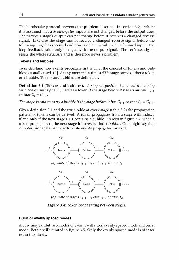
To understand how events propagate in the ring, the concept of tokens and bub-bles is usually used[10]. At any moment in time a STR stage carries either a tokenor a bubble. Tokens and bubbles are defined as:
Definition 3.1 (Tokens and bubbles). A stage at position i in a self-timed ringwith the output signal Ci carries a token if the stage before it has an output Ci−1so that Ci , Ci−1.
The stage is said to carry a bubble if the stage before it has Ci−1 so that Ci = Ci−1.
Given definition 3.1 and the truth table of every stage (table 3.2) the propagationpattern of tokens can be derived. A token propagates from a stage with index iif and only if the next stage i + 1 contains a bubble. As seen in figure 3.4, when atoken propagates to the next stage it leaves behind a bubble. One might say thatbubbles propagate backwards while events propagates forward.
(a) State of stages Ci−1, Ci and Ci+1 at time T1
(b) State of stages Ci−1, Ci and Ci+1 at time T2
Figure 3.4: Token propagating between stages.
Burst or evenly spaced modes
A STR may exhibit two modes of event oscillation: evenly spaced mode and burstmode. Both are illustrated in figure 3.5. Only the evenly spaced mode is of inter-est in this thesis.

3.2 Self-Timed Rings 15
Burst
Evenly-spaced
Figure 3.5: Burst and oscillation modes.
The evenly spaced mode is a direct consequence of a phenomenon called Charlieeffect. Muller-gates have a propagation delay that is a function of the separationtime between its two inputs [11]. The effect of this is that if the request and ac-knowledge signals are close in time, the propagation delay gets higher. However,the propagation delay will get shorter if the request and acknowledge signals ap-pear as further separated in time. This causes events that are close to push awayfrom each other. Eventually the events will spread out evenly throughout thering structure.
In [16], the authors describes that if equation 3.1 is fulfilled evenly spaced modecan be guaranteed.
NTNB≈Df fDrr
(3.1)
Where NT is the number of tokens, NB is the number of bubbles, Df f is the staticpropagation delay on the forwarding input of the Muller-gate and Drr the reverseinput delay.
For the rest of this thesis it is assumed that Df f = Drr since all stages each areimplemented in a single look-up table, as described in section 5.2.1.
Phase distribution
The phase difference between two stages that are n stages apart in a ring of Lstages populated by N evenly spaced events is specified by (3.2)[13].
ϕn = n × NL× 180◦ (3.2)
The phase difference, ϕn, between stages is not only governed by the length ofthe chain, but also the event occupancy of the ring. Equation (3.2) shows that ifL is a multiple of N, some stages will share phase. Also if NB = NT , that is whenthe number of bubbles are equal to the number of tokens, and the propagationdelays of each stage are such that Df f = Drr there will be only four equidistantphases. If N and L are co-prime there will be as many equidistant phases as thereare stages. This is preferable when using STRs for generating entropy. The moreindividual phases there are, the better the phase resolution gets.
∆ϕ =T2L
(3.3)
The phase resolution ∆ϕ of a STR where, the number of stages and events are co-prime and the period T as calculated as equation 3.3. To guarantee that sampling
16 3 Oscillator based true random number generators
occurs within at least one jitter boundary the phase difference should be such that∆ϕ ≤ σ .
3.2.4 Entropy extraction
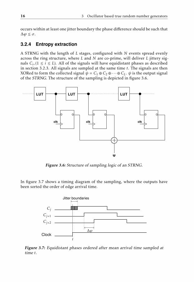
A STRNG with the length of L stages, configured with N events spread evenlyacross the ring structure, where L and N are co-prime, will deliver L jittery sig-nals Ci , (1 ≤ i ≤ L). All of the signals will have equidistant phases as describedin section 3.2.3. All signals are sampled at the same time t. The signals are thenXORed to form the collected signal ψ = C1 ⊕ C2 ⊕ · · · ⊕ CL. ψ is the output signalof the STRNG. The structure of the sampling is depicted in figure 3.6.
Figure 3.6: Structure of sampling logic of an STRNG.
In figure 3.7 shows a timing diagram of the sampling, where the outputs havebeen sorted the order of edge arrival time.
Cj
Cj+1
Cj+2
Clock
Jitter boundaries
∆ϕ
t
Figure 3.7: Equidistant phases ordered after mean arrival time sampled attime t.

3.2 Self-Timed Rings 17
Each sampling takes place at most ∆ϕ2 from an event. That is for every sample
at time t, there exists a stage Cj with a mean arrival time tj so that |t − tj | ≤∆ϕ2 . From this we learn that if ∆ϕ ≤ ρ, where ρ is the jitter magnitude, at least
one signal will have been sampled within the jitter boundaries. Thus when allsampled signals are XORed together, the entropy of the sampled signal ψ has atleast the entropy of the sampled signal sj . The entropy can therefore be denotedas H(ψ) ≥ H(sj ) [11].


4Testing the randomness
This chapter briefly describes which tests are used to evaluate the STRNG in thisthesis.
4.1 Random number testing
Testing if a sequence of random numbers really is random is impossible. To provethat a RNG ’s output is random, an infinite sequence would have to be testedsince a subsequence could be part of a repeating sequence. However, RNGs canbe tested to assert if it is "random enough" for the environment it is used in.
4.2 Batteries and tests used in this studie
In 2014 the author of [17] described and evaluated several modern frameworksfor testing random number generators. The one test-suite recommended is alsothe one best fitted for this thesis: the TestU01 suite. It is a modern, state of theart, test-suite which can be configured according to the user’s needs. Of all of theevaluated frameworks, it was the one best suited for this thesis since it was theonly one that featured a battery specifically made to test true random numbergenerators.
4.2.1 Framework: TestU01
TestU01 is a software library created by Pierre L’Ecuyer at Université de Montreal[18].The library contains several, state of the art, tools to perform statistical tests onRNGs. It is designed so that anyone, with basic C-programming knowledge, can
19
20 4 Testing the randomness
customize the tests to fit the specific needs of the user. To simplify testing fur-ther, the library contains batteries with preconfigured tests that are built to testa specific aspect of a RNG. These are useful to users that are not sure which teststo use. One of the batteries is even designed to test TRNGs. Apart from testingtools TestU01 also contains several pre-implemented PRNGs.
4.2.2 Batteries
The test batteries used in this thesis are Alphabit and BlockAlphabit which aredesigned specifically to test hardware random number generators.
Alphabit
The Alphabit test battery has been created specifically to test hardware basedrandom number generators, which makes it well suited for testing the STRNGimplemented in this thesis. The tests included in the battery are:
1. Binary overlapping serial
2. Hamming independence
3. Hamming correlation
4. Random walk
The binary overlapping test is run in four different configurations, where it testsoverlapping blocks of 2, 4, 8 and 16 bits. The hamming independence tries todetect correlations between overlapping blocks of 16 and 32 bits. The Hammingcorrelation test tests for correlations between 32 bit overlapping blocks. The ran-dom walk tests use walk lengths 64 and 320 bits.
BlockAlphabit
The BlockAlphabit runs the Alphabit battery after reordering the bits in blocksizes of 1, 2, 4, 8, 16 and 32 bits.

5Implementation
This chapter describes how the STRNG was implemented in this thesis, using thestructure described in 3.2.2.
5.1 Configurations
One part of this thesis is to empirically compare different configurations of aSTRNG. Since the wanted behaviour is the evenly spaced event propagation mode,the ratio between the number of tokens and the number of bubbles, NTNB ≈ 1, cannot be changed. The length of the STR, however, can be altered to change thephase resolution. A STR with more elements gets a finer phase resolution whilemaintaining the oscillation period time.
Six different STRs have been implemented with different lengths: 127, 255, 511,1023, 1535 and 2047.
5.2 Logic design
The STRNG structure is designed, using two components: look up tables (LUT )and registers, both housed in the logic blocks on the FPGA. This section specifiesthe implementation used for the Muller-gates and the circuits sued to samplethem.
5.2.1 Muller-gate
Each Muller-gate is implemented in one of the FPGAs LUTs. Each LUT has 4inputs and one output. The first two inputs are used as the forward and reverse
21
22 5 Implementation
inputs, one as a feedback loop from the output and one used for resetting thegate. The feedback loop is used to keep the previous value (see table 3.2). If thefeedback loop is internal the risk is that an unwanted latch is created.
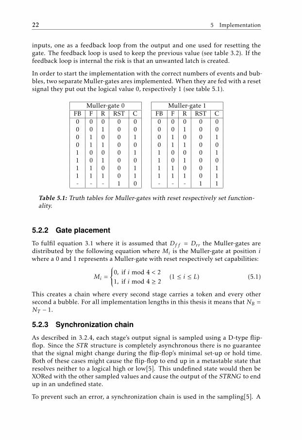
In order to start the implementation with the correct numbers of events and bub-bles, two separate Muller-gates ares implemented. When they are fed with a resetsignal they put out the logical value 0, respectively 1 (see table 5.1).
Muller-gate 0FB F R RST C0 0 0 0 00 0 1 0 00 1 0 0 10 1 1 0 01 0 0 0 11 0 1 0 01 1 0 0 11 1 1 0 1- - - 1 0
Muller-gate 1FB F R RST C0 0 0 0 00 0 1 0 00 1 0 0 10 1 1 0 01 0 0 0 11 0 1 0 01 1 0 0 11 1 1 0 1- - - 1 1
Table 5.1: Truth tables for Muller-gates with reset respectively set function-ality.
5.2.2 Gate placement
To fulfil equation 3.1 where it is assumed that Df f = Drr the Muller-gates aredistributed by the following equation where Mi is the Muller-gate at position iwhere a 0 and 1 represents a Muller-gate with reset respectively set capabilities:
Mi =
0, if i mod 4 < 21, if i mod 4 ≥ 2
(1 ≤ i ≤ L) (5.1)
This creates a chain where every second stage carries a token and every othersecond a bubble. For all implementation lengths in this thesis it means that NB =NT − 1.
5.2.3 Synchronization chain
As described in 3.2.4, each stage’s output signal is sampled using a D-type flip-flop. Since the STR structure is completely asynchronous there is no guaranteethat the signal might change during the flip-flop’s minimal set-up or hold time.Both of these cases might cause the flip-flop to end up in a metastable state thatresolves neither to a logical high or low[5]. This undefined state would then beXORed with the other sampled values and cause the output of the STRNG to endup in an undefined state.
To prevent such an error, a synchronization chain is used in the sampling[5]. A

5.3 Fabric layout 23
second flip-flop is placed in series with the sampling flip-flop creating a synchro-nization chain of length one as depicted in figure 5.1.
Figure 5.1: Synchronization chain at the sampling flip-flop.
The second flip-flop allows for extra time for any eventual metastable signalsbefore it to resolve fully before it is sent to the XOR.
5.3 Fabric layout
This section describes the specializations made to override the compilers defaultlayout.
5.3.1 Combinatorial loops
The implementation of STR contains a combinatorial loop in each stage of thering: the loop feedback signal. This is a problem since the compiler will try tooptimize the structure to not have any combinatorial loops. The problem withthis is that each element may get unpredictable and unwanted properties. Aproblem with the theoretical model would be that Df f = Drr no longer could beassumed.
To make sure the design stays the way it is intended, constraints are put to pre-serve the signals of every stage element. This way each element can be imple-mented in one LUT.
5.3.2 Floor plan
The compiler automatically plans where each component goes on the FPGAs fab-ric if not specified. A problem with this might be that propagation delays be-tween logical elements might differ from stage transition to transition. Althoughthe STRNG structure should be able to handle delay variations between stages[9], the implementation uses a custom floor plan to minimize the risk of errors,caused by events gathering at a slower stage of the ring.
24 5 Implementation
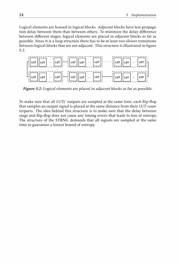
Logical elements are housed in logical blocks. Adjacent blocks have less propaga-tion delay between them than between others. To minimize the delay differencebetween different stages, logical elements are placed in adjacent blocks as far aspossible. Since it is a loop structure there has to be at least two slower transitionsbetween logical blocks that are not adjacent. This structure is illustrated in figure5.2.
Figure 5.2: Logical elements are placed in adjacent blocks as far as possible.
To make sure that all LUTs’ outputs are sampled at the same time, each flip-flopthat samples an output signal is placed at the same distance from their LUT coun-terparts. The idea behind this structure is to make sure that the delay betweenstage and flip-flop does not cause any timing errors that leads to loss of entropy.The structure of the STRNG demands that all signals are sampled at the sametime to guarantee a lowest bound of entropy.
6Results
This chapter describes the results of the measurements of performance and sta-tistical testing results.
6.1 Method
This section 6.1 describes the methods and tools used to measure performanceand to sample data.
6.1.1 Method of sampling randomness
The sampling of bits was done using an USBee SX logic analyser. The internalXOR tree was clocked with an on-board 12MHz clock. The same clock was con-nected to the logic analyser, which was set to trigger on the negative edge toguarantee that the sampled signal had reached a stable state.
According to the USBee SX specifications, it should be able to sample data at24MHz. However when this was tested, the sample tools would for some reasonnot function all the time. Therefore, the sample rate was lowered to half of thespecified limit to make sure that it would function with the set sample rate. Eachsample file gathered and tested contains 640 Million samples.
6.1.2 Method of measuring period time and jitter
An Agilent Infiniium 54832D MSO 1GHz 4GSa/s oscilloscope was used. Unfor-tunately this was the fastest oscilloscope that was available during the work ofthis thesis. It did not have the capabilities to measure the period jitter neededto calculate the individual LUT jitter. However, the oscilloscope had capabilities
25

26 6 Results
to measure and calculate the mean period time of a signal. Knowing the pe-riod time of the STR can be used to calculate the lowest jitter magnitude whichguarantees that a sampled bit is sampled within the jitter boundaries. The out-put signals measured, were connected through low-voltage differential signallingconnections.
6.2 Measurements
This section covers the results of the measurements.
6.2.1 Unexpected behaviour
When measuring the mean oscillation period, three of the STRNG implementa-tions behaved unexpectedly. The implementations with lengths 127 and 2047 didnot lock in to the evenly spaced propagation mode and the one with length 1023showed no evidence of any oscillations. The implementation with 1535 showeda measurement with an anomaly during the measurements but it didn’t appearagain when it was re examined.
All implementations had the same token to bubble ratio, NTNB≈ 1. The only dif-
ference between the implementations were the length of the STR. Theoretically,all implementations should behave as each other withs the only major differencebeing the phase resolution.
Non stable oscillations
In this section, screen captures from the oscilloscope shows the unexpected oscil-lation behaviour. Each implementation has a coloured graph, showing frequencyof occurrence at a certain time, and a normal graph showing a snapshot of non-oscillatory behaviour. Figure 6.1 shows the strange behaviour of the smallest
Figure 6.1: Non stable oscillation from STR with 127 stages.
STR. A stable oscillatory wave can be seen within the coloured graph. However,the occurrence of other waveforms seems to be equally frequent. The right imageshows a strange wave shape occurring between the regular oscillations.

6.2 Measurements 27
Figure 6.2: Non stable oscillation from STR with 2047 stages.
Figure 6.2 shows less oscillatory behaviour than 6.1. The coloured graph does nothave the hinting oscillations of the previous observation and the normal graphshows more irregular waveforms than in the 127 case.
Since no stable oscillation could be achieved, neither of the implementations men-tioned in this section have been used in the statistical testing. They were omittedfrom testing since the theory does not cover any other mode than the one withevenly spaced event propagation.
No oscillations behaviour
The STR with the length of 1023 stages showed no evidence of oscillatory be-haviour at all. Figure 6.3 shows a screen capture from the oscilloscope.
Figure 6.3: Non stable oscillation from STR with 1023 stages.
Even though no oscillation is apparent, the STRNG output exhibited alternatinglogical highs and lows. To further investigate this strange behaviour the STRNGoutput was sampled and subjected to the statistical tests.
Anomaly on stable oscillation
The implementation of length 1535 showed an anomaly once. As seen in figure6.4, a long logical low appeared during period measurements.

28 6 Results
Figure 6.4: A long logical low appeared in the STR with 1535 stages.
The green lines under the stable oscillation represents only a few occurrenceswhere the anomaly appeared.
6.2.2 Stable oscillation
The STRs with lengths 255, 511 and 1535 all exhibited stable oscillations as thetheory prescribes. A screen shot of the behaviour can be seen in figure 6.5.

6.2 Measurements 29
(a) STR of 255 stages.
(b) STR of 511 stages.
(c) STR of 1535 stages.
Figure 6.5: Screen captures from measuring oscillation period. Each pictureshows that the stages oscillates with a stable period.

30 6 Results
6.2.3 Oscillation period
The oscilloscope’s built in functionality for measuring the mean oscillation periodtime was used to learn each stage’s features. Table 6.1 shows the resulting mean
L N T ∆ϕ255 128 2.98ns 4.66ps511 256 2.41ns 2.36ps
1535 768 2.62ns 0.85ps
Table 6.1: Results after measuring period time.
phase resolution ∆ϕ for each implementation that gave a signal in the stableoscillating mode. This gives a value for the minimum jitter magnitude σ thatcan be used in an implementation to guarantee the sampling of a random bit,∆ϕ ≤ σ .
6.3 Test results
Implementations with lengths 127, 1023 and 2047 was left out when conductingthe tests since they did not produce a steady oscillation. Although sampling ofthese signals might have generated good results in statistical testing, it wouldhave been hard to back up the results with any theory.
This section shows the results from testing the implementations of lengths 255,511 and 1535. Each test was run on 640 million sampled bits.
6.3.1 Alphabit battery test results
TestStages
255 511 1535MultinomialBitsOver with L = 2 pass pass failMultinomialBitsOver with L = 4 pass pass failMultinomialBitsOver with L = 8 pass pass failMultinomialBitsOver with L = 16 pass pass failHammingIndep with blocks of L = 16 bits pass pass failHammingIndep with blocks of L = 16 bits pass pass failHammingCorr with blocks of L = 32 bits pass pass failRandomWalk1 with walks of length L = 64 pass pass failRandomWalk1 with walks of length L = 320 pass pass fail
Table 6.2: Test results from Alphabit tests.
6.3 Test results 31
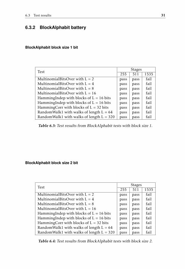
6.3.2 BlockAlphabit battery
BlockAlphabit block size 1 bit
TestStages
255 511 1535MultinomialBitsOver with L = 2 pass pass failMultinomialBitsOver with L = 4 pass pass failMultinomialBitsOver with L = 8 pass pass failMultinomialBitsOver with L = 16 pass pass failHammingIndep with blocks of L = 16 bits pass pass failHammingIndep with blocks of L = 16 bits pass pass failHammingCorr with blocks of L = 32 bits pass pass failRandomWalk1 with walks of length L = 64 pass pass failRandomWalk1 with walks of length L = 320 pass pass fail
Table 6.3: Test results from BlockAlphabit tests with block size 1.
BlockAlphabit block size 2 bit
TestStages
255 511 1535MultinomialBitsOver with L = 2 pass pass failMultinomialBitsOver with L = 4 pass pass failMultinomialBitsOver with L = 8 pass pass failMultinomialBitsOver with L = 16 pass pass failHammingIndep with blocks of L = 16 bits pass pass failHammingIndep with blocks of L = 16 bits pass pass failHammingCorr with blocks of L = 32 bits pass pass failRandomWalk1 with walks of length L = 64 pass pass failRandomWalk1 with walks of length L = 320 pass pass fail
Table 6.4: Test results from BlockAlphabit tests with block size 2.

32 6 Results
BlockAlphabit block size 4 bit
TestStages
255 511 1535MultinomialBitsOver with L = 2 pass pass failMultinomialBitsOver with L = 4 pass pass failMultinomialBitsOver with L = 8 pass pass failMultinomialBitsOver with L = 16 pass pass failHammingIndep with blocks of L = 16 bits pass pass failHammingIndep with blocks of L = 16 bits pass pass failHammingCorr with blocks of L = 32 bits pass pass failRandomWalk1 with walks of length L = 64 pass pass failRandomWalk1 with walks of length L = 320 pass pass fail
Table 6.5: Test results from BlockAlphabit tests with block size 4.
BlockAlphabit block size 8 bit
TestStages
255 511 1535MultinomialBitsOver with L = 2 pass pass failMultinomialBitsOver with L = 4 pass pass failMultinomialBitsOver with L = 8 pass pass failMultinomialBitsOver with L = 16 pass pass failHammingIndep with blocks of L = 16 bits pass pass failHammingIndep with blocks of L = 16 bits pass pass failHammingCorr with blocks of L = 32 bits pass pass failRandomWalk1 with walks of length L = 64 pass pass failRandomWalk1 with walks of length L = 320 pass pass fail
Table 6.6: Test results from BlockAlphabit tests with block size 8.

6.3 Test results 33
BlockAlphabit block size 16 bit
TestStages
255 511 1535MultinomialBitsOver with L = 2 pass pass failMultinomialBitsOver with L = 4 pass pass failMultinomialBitsOver with L = 8 pass pass failMultinomialBitsOver with L = 16 pass pass failHammingIndep with blocks of L = 16 bits pass pass failHammingIndep with blocks of L = 16 bits pass pass failHammingCorr with blocks of L = 32 bits pass pass failRandomWalk1 with walks of length L = 64 pass pass failRandomWalk1 with walks of length L = 320 pass pass fail
Table 6.7: Test results from BlockAlphabit tests with block size 16.
BlockAlphabit block size 32 bit
TestStages
255 511 1535MultinomialBitsOver with L = 2 pass pass failMultinomialBitsOver with L = 4 pass pass failMultinomialBitsOver with L = 8 pass pass failMultinomialBitsOver with L = 16 pass pass failHammingIndep with blocks of L = 16 bits pass pass failHammingIndep with blocks of L = 16 bits pass pass failHammingCorr with blocks of L = 32 bits pass pass failRandomWalk1 with walks of length L = 64 pass pass failRandomWalk1 with walks of length L = 320 pass pass fail
Table 6.8: Test results from BlockAlphabit tests with block size 32.


7Conclusion
This chapter contains conclusions drawn during the thesis work and also recom-mends what needs to be done in the future of the development of the STRNG.
7.1 Self-timed ring as random number generator
Generating truly random numbers is no trivial task. Especially not when imple-menting for FPGA hardware. Most secure systems rely on pseudo random num-ber generators to provide random sequences. Most of them have long periodsbefore they start to repeat themselves, have good statistical properties and gener-ates seemingly random bits at a high rate. But for any PRNG to truly be useful,they need to have a good source of entropy to seed them. This is especially truein cryptographic systems where predictable or manipulatable random numberscould pose as a back door to breach security.
Implementing cryptographic functions on FPGA hardware is faster to develop,cheaper and more maintainable than using specially built hardware. Flaws, ifdetected, can be patched and fixed without the need of having to change anyhardware.
It has been shown that a self-timed ring structure could work as a good alter-native to jittery clocks based on inverter ring oscillators. Inverter rings are verysensitive to temperature which might cause problems since it is an environmentalvariable that is rather hard to control. Especially if the system implementing it isused in a shifting environment or is close to other systems that tend to emit vary-ing temperatures. Voltage changes is also a factor that inverter rings are sensitiveto. The authors of [10] showed that self-timed rings can be made less sensitive tovoltage variations by increasing the length of the ring stage.
35
36 7 Conclusion
7.2 Implementation
In this paper it has been shown that self-timed ring random number generatorsseems to work quite well on the FPGA hardware that was used. Although someof the implementations showed unexpected behaviour, two of the implementedSTRNGs exhibited stable oscillations that seemed to generate random data withgood features.
The implementation featuring 1535 stages showed an anomaly in one measure-ment of the oscillation period. This might have been caused by a measurementerror caused by the equipment used. It might also be proof of some eventsgrouping-up where a transition delay between two stages were higher than av-erage in the structure. If so this could be the effect of the transition between twological blocks that were not next to each other in the hardware.
The implementations of lengths 127 and 2047 showed no evidence of lockingin to a steady oscillation. This suggests that events were not spread out evenlyacross the structure and instead a burst-like mode appeared. However, accordingto the theories should the Charlie effect should be equally strong in all the imple-mentation, causing the events to lock into a steady oscillation. A possible reasonfor the strange behaviour could be that these specific lengths might have causedthe logical blocks to use a slower transition, than the other implementations, be-tween blocks that are not adjacent.
The behaviour of the implementation of length 1023 is the strangest of the mea-surements. The output of the STRNG showed both logical highs and lows whenno oscillation was seen on the measurements. A possible explanation for thiscould be that all stages somehow locked themselves in an undefined logical valuewhich caused the output to vary. What may have caused this behaviour is un-known.
7.3 Testing
Testing of random number generators can never be done to prove that it is com-pletely random. To do that the RNG would have to undergo tests for an infinitelylong sequence. This is true since all finite sequences could be part of a largerrepeating sequence. However, testing of RNGs can be used as a tool to makesure that the output is random "enough", meaning that the properties of the RNGfulfil the requirements needed in the context of which it is used.
The STRNG implementations that showed good properties in the measuring phasealso showed good results in the tests. All tests were passed for the STRNGs oflengths 255 and 511. This indicates that the self-timed ring structure very wellmay work on the requested hardware. However, since the other four implemen-tations exhibited unwanted behaviour it cannot be concluded that the currentimplementation is suitable for implementation just yet.

7.4 Future work 37
7.4 Future work
A correct jitter measurement is needed to make an analysis of the entropy eachsampled bit contains. The measured values gathered in this thesis could be usedas hints towards fine tuning a final implementation so that the phase resolutionfits the jitter magnitude as good as possible.
Biased data could be a problem in a real-world implementation of the STRNG.Some form of anti-biasing post processing should be examined.
Some implementations worked as described in the theory and others showed un-expected behaviour. It cannot be concluded that the implementation is perfectlysuited for the specified hardware. The unexpected behaviour should be morethoroughly analysed to find out if there is anything about the implementationthat makes the strange behaviour occur.
An important aspect of STRNG -security is resistance towards deterministic jittersources. Tests should be carried out where bits are sampled while the tempera-tures and voltage sources are altered. STRs are proposed to be more robust thanIROs when it comes to such variations. This needs to be proven to make sure thatattacks against the STRNG can be carried out through increasing the impact ofdeterministic jitter sources.


Appendix


ATest result summaries
This chapter contains the test result summaries from the Alphabit and Block-Alphabit batteries. Each section contains the result for a separate implementa-tions.
A.1 Alphabit battery
A.1.1 STRNG length 255
========= Summary results of Alphabit =========
Version: TestU01 1.2.3File: short-random-bitsNumber of bits: 640024576Number of statistics: 17Total CPU time: 00:00:19.89
All tests were passed
A.1.2 STRNG length 511
========= Summary results of Alphabit =========
Version: TestU01 1.2.3File: long-random-bitsNumber of bits: 640024576Number of statistics: 17Total CPU time: 00:00:25.95
41

42 A Test result summaries
All tests were passed
A.1.3 STRNG length 1535========= Summary results of Alphabit =========
Version: TestU01 1.2.3File: longer2-random-bitsNumber of bits: 640024576Number of statistics: 17Total CPU time: 00:00:20.00The following tests gave p-values outside [0.001, 0.9990]:(eps means a value < 1.0e-300):(eps1 means a value < 1.0e-15):
Test p-value----------------------------------------------1 MultinomialBitsOver, L = 2 eps2 MultinomialBitsOver, L = 4 eps3 MultinomialBitsOver, L = 8 eps4 MultinomialBitsOver, L = 16 eps5 HammingIndep, L = 16 eps6 HammingIndep, L = 32 eps7 HammingCorr, L = 32 eps8 RandomWalk1 H (L = 64) eps8 RandomWalk1 M (L = 64) eps8 RandomWalk1 J (L = 64) eps8 RandomWalk1 R (L = 64) eps8 RandomWalk1 C (L = 64) eps9 RandomWalk1 H (L = 320) eps9 RandomWalk1 M (L = 320) eps9 RandomWalk1 J (L = 320) eps9 RandomWalk1 R (L = 320) eps9 RandomWalk1 C (L = 320) eps
----------------------------------------------
A.2 BlockAlphabit battery
A.2.1 STRNG length 255
Block size 1
========= Summary results of Alphabit =========
Version: TestU01 1.2.3File: short-random-bitsNumber of bits: 640024576Number of statistics: 17Total CPU time: 00:00:25.78

A.2 BlockAlphabit battery 43
All tests were passed
Block size 2
========= Summary results of Alphabit =========
Version: TestU01 1.2.3File: short-random-bitsNumber of bits: 640024576Number of statistics: 17Total CPU time: 00:00:22.84
All tests were passed
Block size 4
========= Summary results of Alphabit =========
Version: TestU01 1.2.3File: short-random-bitsNumber of bits: 640024576Number of statistics: 17Total CPU time: 00:00:21.29
All tests were passed
Block size 8
========= Summary results of Alphabit =========
Version: TestU01 1.2.3File: short-random-bitsNumber of bits: 640024576Number of statistics: 17Total CPU time: 00:00:20.48
All tests were passed
Block size 16
========= Summary results of Alphabit =========
Version: TestU01 1.2.3File: short-random-bitsNumber of bits: 640024576Number of statistics: 17Total CPU time: 00:00:20.34
All tests were passed
Block size 32
========= Summary results of Alphabit =========

44 A Test result summaries
Version: TestU01 1.2.3File: short-random-bitsNumber of bits: 640024576Number of statistics: 17Total CPU time: 00:00:20.18
All tests were passed
A.2.2 STRNG length 511
Block size 1
========= Summary results of Alphabit =========
Version: TestU01 1.2.3File: long-random-bitsNumber of bits: 640024576Number of statistics: 17Total CPU time: 00:00:25.95
All tests were passed
Block size 2
========= Summary results of Alphabit =========
Version: TestU01 1.2.3File: long-random-bitsNumber of bits: 640024576Number of statistics: 17Total CPU time: 00:00:22.65
All tests were passed
Block size 4
========= Summary results of Alphabit =========
Version: TestU01 1.2.3File: long-random-bitsNumber of bits: 640024576Number of statistics: 17Total CPU time: 00:00:21.20
All tests were passed
Block size 8
========= Summary results of Alphabit =========
Version: TestU01 1.2.3File: long-random-bitsNumber of bits: 640024576

A.2 BlockAlphabit battery 45
Number of statistics: 17Total CPU time: 00:00:20.42
All tests were passed
Block size 16
========= Summary results of Alphabit =========
Version: TestU01 1.2.3File: long-random-bitsNumber of bits: 640024576Number of statistics: 17Total CPU time: 00:00:20.28
All tests were passed
Block size 32
========= Summary results of Alphabit =========
Version: TestU01 1.2.3File: long-random-bitsNumber of bits: 640024576Number of statistics: 17Total CPU time: 00:00:20.09
All tests were passed
A.2.3 STRNG length 1535
Block size 1
========= Summary results of Alphabit =========
Version: TestU01 1.2.3File: longer2-random-bitsNumber of bits: 640024576Number of statistics: 17Total CPU time: 00:00:25.79The following tests gave p-values outside [0.001, 0.9990]:(eps means a value < 1.0e-300):(eps1 means a value < 1.0e-15):
Test p-value----------------------------------------------1 MultinomialBitsOver, L = 2 eps2 MultinomialBitsOver, L = 4 eps3 MultinomialBitsOver, L = 8 eps4 MultinomialBitsOver, L = 16 eps5 HammingIndep, L = 16 eps6 HammingIndep, L = 32 eps

46 A Test result summaries
7 HammingCorr, L = 32 eps8 RandomWalk1 H (L = 64) eps8 RandomWalk1 M (L = 64) eps8 RandomWalk1 J (L = 64) eps8 RandomWalk1 R (L = 64) eps8 RandomWalk1 C (L = 64) eps9 RandomWalk1 H (L = 320) eps9 RandomWalk1 M (L = 320) eps9 RandomWalk1 J (L = 320) eps9 RandomWalk1 R (L = 320) eps9 RandomWalk1 C (L = 320) eps
----------------------------------------------
Block size 2
========= Summary results of Alphabit =========
Version: TestU01 1.2.3File: longer2-random-bitsNumber of bits: 640024576Number of statistics: 17Total CPU time: 00:00:22.75The following tests gave p-values outside [0.001, 0.9990]:(eps means a value < 1.0e-300):(eps1 means a value < 1.0e-15):
Test p-value----------------------------------------------1 MultinomialBitsOver, L = 2 eps2 MultinomialBitsOver, L = 4 eps3 MultinomialBitsOver, L = 8 eps4 MultinomialBitsOver, L = 16 eps5 HammingIndep, L = 16 eps6 HammingIndep, L = 32 eps7 HammingCorr, L = 32 eps8 RandomWalk1 H (L = 64) eps8 RandomWalk1 M (L = 64) eps8 RandomWalk1 J (L = 64) eps8 RandomWalk1 R (L = 64) eps8 RandomWalk1 C (L = 64) eps9 RandomWalk1 H (L = 320) eps9 RandomWalk1 M (L = 320) eps9 RandomWalk1 J (L = 320) eps9 RandomWalk1 R (L = 320) eps9 RandomWalk1 C (L = 320) eps
----------------------------------------------
Block size 4
========= Summary results of Alphabit =========
Version: TestU01 1.2.3

A.2 BlockAlphabit battery 47
File: longer2-random-bitsNumber of bits: 640024576Number of statistics: 17Total CPU time: 00:00:21.18The following tests gave p-values outside [0.001, 0.9990]:(eps means a value < 1.0e-300):(eps1 means a value < 1.0e-15):
Test p-value----------------------------------------------1 MultinomialBitsOver, L = 2 eps2 MultinomialBitsOver, L = 4 eps3 MultinomialBitsOver, L = 8 eps4 MultinomialBitsOver, L = 16 eps5 HammingIndep, L = 16 eps6 HammingIndep, L = 32 eps7 HammingCorr, L = 32 eps8 RandomWalk1 H (L = 64) eps8 RandomWalk1 M (L = 64) eps8 RandomWalk1 J (L = 64) eps8 RandomWalk1 R (L = 64) eps8 RandomWalk1 C (L = 64) eps9 RandomWalk1 H (L = 320) eps9 RandomWalk1 M (L = 320) eps9 RandomWalk1 J (L = 320) eps9 RandomWalk1 R (L = 320) eps9 RandomWalk1 C (L = 320) eps
----------------------------------------------
Block size 8
========= Summary results of Alphabit =========
Version: TestU01 1.2.3File: longer2-random-bitsNumber of bits: 640024576Number of statistics: 17Total CPU time: 00:00:20.37The following tests gave p-values outside [0.001, 0.9990]:(eps means a value < 1.0e-300):(eps1 means a value < 1.0e-15):
Test p-value----------------------------------------------1 MultinomialBitsOver, L = 2 eps2 MultinomialBitsOver, L = 4 eps3 MultinomialBitsOver, L = 8 eps4 MultinomialBitsOver, L = 16 eps5 HammingIndep, L = 16 eps6 HammingIndep, L = 32 eps7 HammingCorr, L = 32 eps

48 A Test result summaries
8 RandomWalk1 H (L = 64) eps8 RandomWalk1 M (L = 64) eps8 RandomWalk1 J (L = 64) eps8 RandomWalk1 R (L = 64) eps8 RandomWalk1 C (L = 64) eps9 RandomWalk1 H (L = 320) eps9 RandomWalk1 M (L = 320) eps9 RandomWalk1 J (L = 320) eps9 RandomWalk1 R (L = 320) eps9 RandomWalk1 C (L = 320) eps
----------------------------------------------
Block size 16
========= Summary results of Alphabit =========
Version: TestU01 1.2.3File: longer2-random-bitsNumber of bits: 640024576Number of statistics: 17Total CPU time: 00:00:20.25The following tests gave p-values outside [0.001, 0.9990]:(eps means a value < 1.0e-300):(eps1 means a value < 1.0e-15):
Test p-value----------------------------------------------1 MultinomialBitsOver, L = 2 eps2 MultinomialBitsOver, L = 4 eps3 MultinomialBitsOver, L = 8 eps4 MultinomialBitsOver, L = 16 eps5 HammingIndep, L = 16 eps6 HammingIndep, L = 32 eps7 HammingCorr, L = 32 eps8 RandomWalk1 H (L = 64) eps8 RandomWalk1 M (L = 64) eps8 RandomWalk1 J (L = 64) eps8 RandomWalk1 R (L = 64) eps8 RandomWalk1 C (L = 64) eps9 RandomWalk1 H (L = 320) eps9 RandomWalk1 M (L = 320) eps9 RandomWalk1 J (L = 320) eps9 RandomWalk1 R (L = 320) eps9 RandomWalk1 C (L = 320) eps
----------------------------------------------
Block size 32
========= Summary results of Alphabit =========
Version: TestU01 1.2.3File: longer2-random-bits

A.2 BlockAlphabit battery 49
Number of bits: 640024576Number of statistics: 17Total CPU time: 00:00:20.11The following tests gave p-values outside [0.001, 0.9990]:(eps means a value < 1.0e-300):(eps1 means a value < 1.0e-15):
Test p-value----------------------------------------------1 MultinomialBitsOver, L = 2 eps2 MultinomialBitsOver, L = 4 eps3 MultinomialBitsOver, L = 8 eps4 MultinomialBitsOver, L = 16 eps5 HammingIndep, L = 16 eps6 HammingIndep, L = 32 eps7 HammingCorr, L = 32 eps8 RandomWalk1 H (L = 64) eps8 RandomWalk1 M (L = 64) eps8 RandomWalk1 J (L = 64) eps8 RandomWalk1 R (L = 64) eps8 RandomWalk1 C (L = 64) eps9 RandomWalk1 H (L = 320) eps9 RandomWalk1 M (L = 320) eps9 RandomWalk1 J (L = 320) eps9 RandomWalk1 R (L = 320) eps9 RandomWalk1 C (L = 320) eps
----------------------------------------------

50 A Test result summaries

Bibliography
[1] The american heritage dictionary entry: random. URL https://www.ahdictionary.com/word/search.html?q=random. Accessed: 2015-05-14. Cited on page 5.
[2] Random meaning, definition in cambridge english dictionary. URL http://dictionary.cambridge.org/dictionary/british/random. Ac-cessed: 2015-05-14. Cited on page 5.
[3] Random | define random at dictionary.com. URL http://dictionary.reference.com/browse/random?s=t. Accessed: 2015-05-14. Cited onpage 5.
[4] Random - definition of random in english from the oxford dictio-nary. URL http://www.oxforddictionaries.com/definition/english/random. Accessed: 2015-01-26. Cited on page 5.
[5] Altera. Understanding metastability in FPGAs, 2009. URL https://www.altera.com/content/dam/altera-www/global/en_US/pdfs/literature/wp/wp-01082-quartus-ii-metastability.pdf.Cited on page 22.
[6] Mark Balch. Complete digital design : A comprehensive guide to digitalelectronics and computer system architecture / m. balch. 2003. Cited onpage 7.
[7] Deborah J. Bennett. Randomness. Harvard University Press, Cambridge,MA, USA, 1998. ISBN 9780674020771. URL http://site.ebrary.com/lib/alltitles/docDetail.action?docID=10331355. Citedon page 1.
[8] A. Cherkaoui, L. Fesquet, V. Fischer, and A. Aubert. Self-timed rings asentropy sources. In 18th IEEE International Symposium on AsynchronousCircuits and Systems (ASYNC), page pp, Copenhagen, Denmark, May 2012.URL https://hal.archives-ouvertes.fr/hal-00747383. Citedon pages 2, 3, and 12.
51

52 Bibliography
[9] A. Cherkaoui, V. Fischer, A. Aubert, and L. Fesquet. A self-timed ring basedtrue random number generator. In 2013 IEEE 19th International Sympo-sium on Asynchronous Circuits and Systems (ASYNC), pages 99–106, May2013. doi: 10.1109/ASYNC.2013.15. Cited on pages 2, 3, 8, 12, and 23.
[10] Abdelkarim Cherkaoui, Viktor Fischer, Alain Aubert, and Laurent Fes-quet. Comparison of self-timed ring and inverter ring oscillators as entropysources in FPGAs. In Proceedings of the Conference on Design, Automationand Test in Europe, DATE ’12, pages 1325–1330, San Jose, CA, USA, 2012.EDA Consortium. ISBN 978-3-9810801-8-6. URL http://dl.acm.org/citation.cfm?id=2492708.2493034. Cited on pages 2, 3, 11, 12, 14,and 35.
[11] Abdelkarim Cherkaoui, Viktor Fischer, Laurent Fesquet, and Alain Aubert.A very high speed true random number generator with entropy assessment.In Guido Bertoni and Jean-Sébastien Coron, editors, Cryptographic Hard-ware and Embedded Systems - CHES 2013, number 8086 in Lecture Notesin Computer Science, pages 179–196. Springer Berlin Heidelberg, January2013. ISBN 978-3-642-40348-4, 978-3-642-40349-1. URL http://link.springer.com/chapter/10.1007/978-3-642-40349-1_11. Citedon pages 2, 3, 8, 12, 15, and 17.
[12] Thomas M. Cover and Joy A. Thomas. Elements of information theory.Hoboken, N.J. : Wiley, cop. 2006, 2006. ISBN 0471241954. Cited on page 6.
[13] Scott Michael Fairbanks. High precision timing using self-timed circuits.Ph.d., University of Cambridge, 2009. URL http://ethos.bl.uk/OrderDetails.do?uin=uk.bl.ethos.615033? Cited on page 15.
[14] Niels Ferguson, Bruce Schneier, Tadayoshi Kohno, and Niels Ferguson.Cryptography engineering : design principles and practical applications. In-dianapolis, IN : Wiley, c2010., 2010. ISBN 9780470474242. Cited on page6.
[15] V. Fischer, F. Bernard, N. Bochard, and M. Varchola. Enhancing security ofring oscillator-based trng implemented in FPGA. In International Confer-ence on Field Programmable Logic and Applications, 2008. FPL 2008, pages245–250, September 2008. doi: 10.1109/FPL.2008.4629939. Cited on page7.
[16] J. Hamon, L. Fesquet, B. Miscopein, and M. Renaudin. High-level time-accurate model for the design of self-timed ring oscillators. In 14th IEEEInternational Symposium on Asynchronous Circuits and Systems, 2008.ASYNC ’08, pages 29–38, April 2008. doi: 10.1109/ASYNC.2008.16. Citedon page 15.
[17] Krister Sune Jakobsson. Theory, Methods and Tools for Statistical Test-ing of Pseudo and Quantum Random Number Generators. 2014. URLhttp://liu.diva-portal.org/smash/record.jsf?aq2=%5B%5B%5D%5D&af=%5B%5D&searchType=SIMPLE&language=sv&pid=

Bibliography 53
diva2%3A740158&aq=%5B%5B%5D%5D&jfwid=-1717&sf=all&aqe=%5B%5D&sortOrder=author_sort_asc&onlyFullText=false&noOfRows=50&dswid=1906. Cited on pages 3 and 19.
[18] Pierre L’Ecuyer and Richard Simard. TestU01: A c library for empiricaltesting of random number generators. ACM Trans. Math. Softw., 33(4),August 2007. ISSN 0098-3500. doi: 10.1145/1268776.1268777. URLhttp://doi.acm.org/10.1145/1268776.1268777. Cited on page 19.
[19] Maitham Shams, Jo C. Ebergen, and Mohamed I. Elmasry. AsynchronousCircuits. Cited on pages 12 and 13.
[20] I. E. Sutherland. Micropipelines. Commun. ACM, 32(6):720–738, June1989. ISSN 0001-0782. doi: 10.1145/63526.63532. URL http://doi.acm.org/10.1145/63526.63532. Cited on pages 12 and 13.

54 Bibliography

Upphovsrätt
Detta dokument hålls tillgängligt på Internet — eller dess framtida ersättare —under 25 år från publiceringsdatum under förutsättning att inga extraordinäraomständigheter uppstår.
Tillgång till dokumentet innebär tillstånd för var och en att läsa, ladda ner,skriva ut enstaka kopior för enskilt bruk och att använda det oförändrat för icke-kommersiell forskning och för undervisning. Överföring av upphovsrätten viden senare tidpunkt kan inte upphäva detta tillstånd. All annan användning avdokumentet kräver upphovsmannens medgivande. För att garantera äktheten,säkerheten och tillgängligheten finns det lösningar av teknisk och administrativart.
Upphovsmannens ideella rätt innefattar rätt att bli nämnd som upphovsmani den omfattning som god sed kräver vid användning av dokumentet på ovanbeskrivna sätt samt skydd mot att dokumentet ändras eller presenteras i sådanform eller i sådant sammanhang som är kränkande för upphovsmannens litteräraeller konstnärliga anseende eller egenart.
För ytterligare information om Linköping University Electronic Press se förla-gets hemsida http://www.ep.liu.se/
Copyright
The publishers will keep this document online on the Internet — or its possi-ble replacement — for a period of 25 years from the date of publication barringexceptional circumstances.
The online availability of the document implies a permanent permission foranyone to read, to download, to print out single copies for his/her own use andto use it unchanged for any non-commercial research and educational purpose.Subsequent transfers of copyright cannot revoke this permission. All other usesof the document are conditional on the consent of the copyright owner. Thepublisher has taken technical and administrative measures to assure authenticity,security and accessibility.
According to intellectual property law the author has the right to be men-tioned when his/her work is accessed as described above and to be protectedagainst infringement.
For additional information about the Linköping University Electronic Pressand its procedures for publication and for assurance of document integrity, pleaserefer to its www home page: http://www.ep.liu.se/
© Marcus Einar


