Aruba CampusWNetworksVRD
154
Aruba Campus Wireless Networks Version 8
-
Upload
hamid-hoteit -
Category
Documents
-
view
234 -
download
0
Transcript of Aruba CampusWNetworksVRD
Aruba Campus Wireless NetworksVersion 8
Aruba Campus Wireless Networks Validated Reference Design
Copyright© 2012 Aruba Networks, Inc. AirWave®, Aruba Networks®, Aruba Mobility Management System®, Bluescanner, For Wireless That Works®, Mobile Edge Architecture®, People Move. Networks Must Follow®, RFprotect®, The All Wireless Workplace Is Now Open For Business, Green Island, and The Mobile Edge Company® are trademarks of Aruba Networks, Inc. All rights reserved. Aruba Networks reserves the right to change, modify, transfer, or otherwise revise this publication and the product specifications without notice. While Aruba uses commercially reasonable efforts to ensure the accuracy of the specifications contained in this document, Aruba will assume no responsibility for any errors or omissions.
Open Source CodeCertain Aruba products include Open Source software code developed by third parties, including software code subject to the GNU General Public License (“GPL”), GNU Lesser General Public License (“LGPL”), or other Open Source Licenses. The Open Source code used can be found at this site:
http://www.arubanetworks.com/open_source
Legal NoticeARUBA DISCLAIMS ANY AND ALL OTHER REPRESENTATIONS AND WARRANTIES, WEATHER EXPRESS, IMPLIED, OR STATUTORY, INCLUDING WARRANTIES OF MERCHANTABILITY, FITNESS FOR A PARTICULAR PURPOSE, TITLE, NONINFRINGEMENT, ACCURACY AND QUET ENJOYMENT. IN NO EVENT SHALL THE AGGREGATE LIABILITY OF ARUBA EXCEED THE AMOUNTS ACUTALLY PAID TO ARUBA UNDER ANY APPLICABLE WRITTEN AGREEMENT OR FOR ARUBA PRODUCTS OR SERVICES PURSHASED DIRECTLY FROM ARUBA, WHICHEVER IS LESS.
www.arubanetworks.com
1344 Crossman AvenueSunnyvale, California 94089
Phone: 408.227.4500Fax 408.227.4550
Aruba Networks, Inc. 2
Aruba Campus Wireless Networks Validated Reference Design
Table of Contents
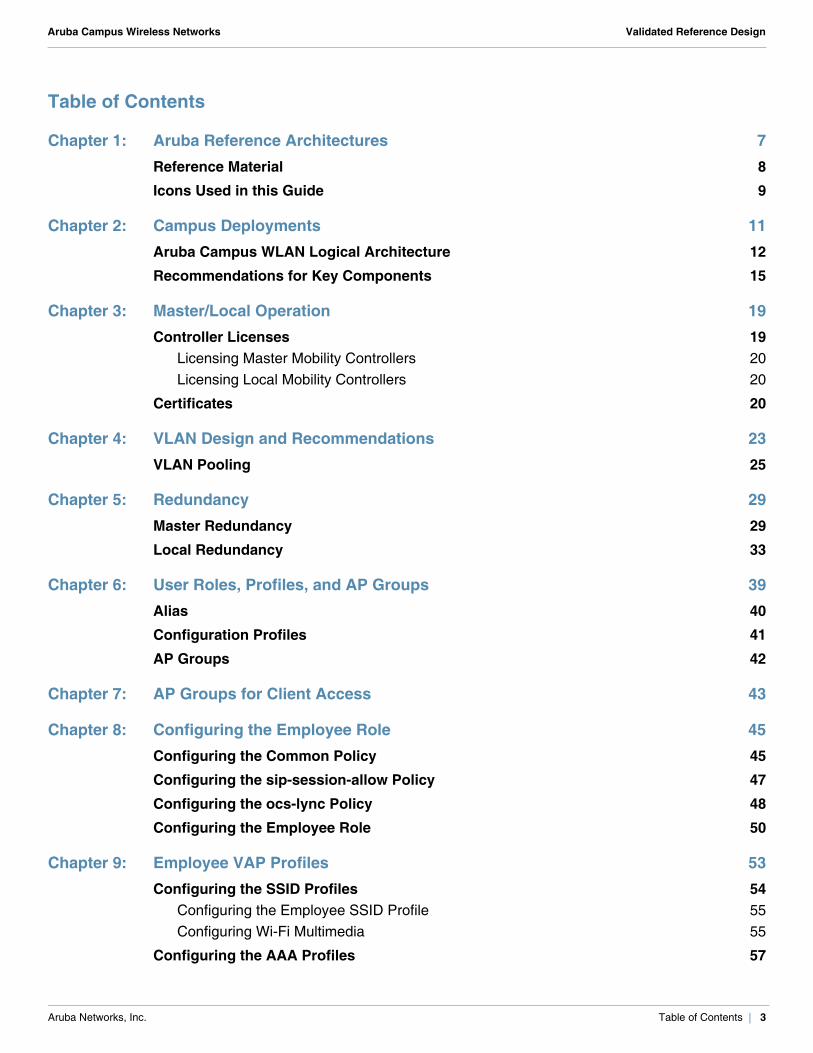
Chapter 1: Aruba Reference Architectures 7Reference Material 8Icons Used in this Guide 9
Chapter 2: Campus Deployments 11Aruba Campus WLAN Logical Architecture 12Recommendations for Key Components 15
Chapter 3: Master/Local Operation 19Controller Licenses 19
Licensing Master Mobility Controllers 20Licensing Local Mobility Controllers 20
Certificates 20
Chapter 4: VLAN Design and Recommendations 23VLAN Pooling 25
Chapter 5: Redundancy 29Master Redundancy 29Local Redundancy 33
Chapter 6: User Roles, Profiles, and AP Groups 39Alias 40Configuration Profiles 41AP Groups 42
Chapter 7: AP Groups for Client Access 43
Chapter 8: Configuring the Employee Role 45Configuring the Common Policy 45Configuring the sip-session-allow Policy 47Configuring the ocs-lync Policy 48Configuring the Employee Role 50
Chapter 9: Employee VAP Profiles 53Configuring the SSID Profiles 54
Configuring the Employee SSID Profile 55Configuring Wi-Fi Multimedia 55
Configuring the AAA Profiles 57
Aruba Networks, Inc. Table of Contents | 3
Aruba Campus Wireless Networks Validated Reference Design
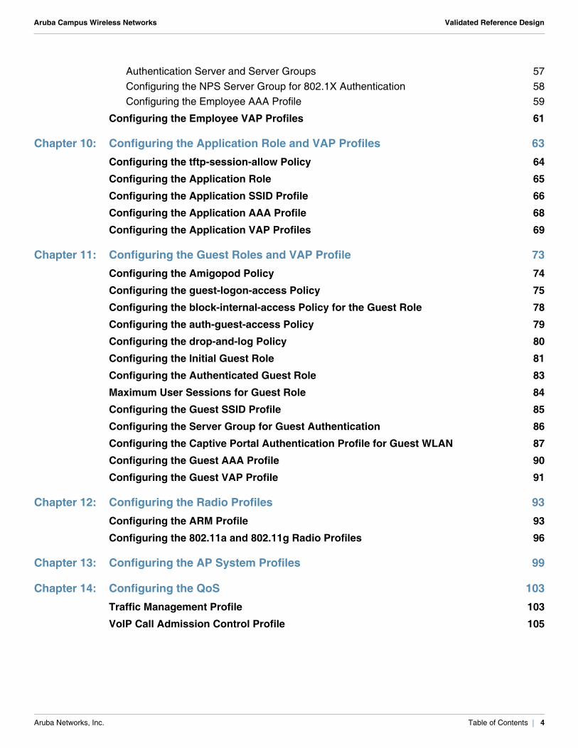
Authentication Server and Server Groups 57Configuring the NPS Server Group for 802.1X Authentication 58Configuring the Employee AAA Profile 59
Configuring the Employee VAP Profiles 61
Chapter 10: Configuring the Application Role and VAP Profiles 63Configuring the tftp-session-allow Policy 64Configuring the Application Role 65Configuring the Application SSID Profile 66Configuring the Application AAA Profile 68Configuring the Application VAP Profiles 69
Chapter 11: Configuring the Guest Roles and VAP Profile 73Configuring the Amigopod Policy 74Configuring the guest-logon-access Policy 75Configuring the block-internal-access Policy for the Guest Role 78Configuring the auth-guest-access Policy 79Configuring the drop-and-log Policy 80Configuring the Initial Guest Role 81Configuring the Authenticated Guest Role 83Maximum User Sessions for Guest Role 84Configuring the Guest SSID Profile 85Configuring the Server Group for Guest Authentication 86Configuring the Captive Portal Authentication Profile for Guest WLAN 87Configuring the Guest AAA Profile 90Configuring the Guest VAP Profile 91
Chapter 12: Configuring the Radio Profiles 93Configuring the ARM Profile 93Configuring the 802.11a and 802.11g Radio Profiles 96
Chapter 13: Configuring the AP System Profiles 99
Chapter 14: Configuring the QoS 103Traffic Management Profile 103VoIP Call Admission Control Profile 105
Aruba Networks, Inc. Table of Contents | 4
Aruba Campus Wireless Networks Validated Reference Design
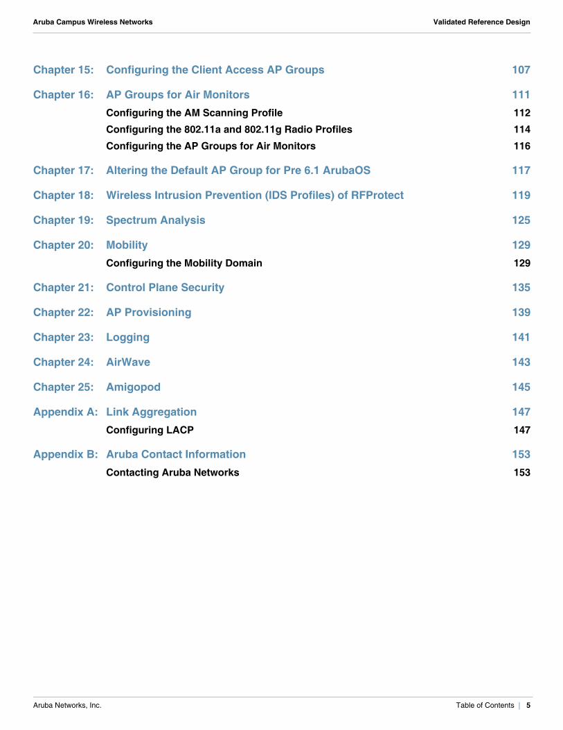
Chapter 15: Configuring the Client Access AP Groups 107
Chapter 16: AP Groups for Air Monitors 111Configuring the AM Scanning Profile 112Configuring the 802.11a and 802.11g Radio Profiles 114Configuring the AP Groups for Air Monitors 116
Chapter 17: Altering the Default AP Group for Pre 6.1 ArubaOS 117
Chapter 18: Wireless Intrusion Prevention (IDS Profiles) of RFProtect 119
Chapter 19: Spectrum Analysis 125
Chapter 20: Mobility 129Configuring the Mobility Domain 129
Chapter 21: Control Plane Security 135
Chapter 22: AP Provisioning 139
Chapter 23: Logging 141
Chapter 24: AirWave 143
Chapter 25: Amigopod 145
Appendix A: Link Aggregation 147Configuring LACP 147
Appendix B: Aruba Contact Information 153Contacting Aruba Networks 153
Aruba Networks, Inc. Table of Contents | 5

Aruba Campus Wireless Networks Validated Reference Design
Aruba Networks, Inc. Table of Contents | 6
Aruba Campus Wireless Networks Validated Reference Design
Chapter 1: Aruba Reference Architectures
The Aruba Validated Reference Design (VRD) series is a collection of technology deployment guides that include descriptions of Aruba technology, recommendations for product selections, network design decisions, configuration procedures, and best practices for deployment. Together these guides comprise a reference model for understanding Aruba technology and designs for common customer deployment scenarios. Each Aruba VRD network design has been constructed in a lab environment and thoroughly tested by Aruba engineers. Our customers use these proven designs to rapidly deploy Aruba solutions in production with the assurance that they will perform and scale as expected.
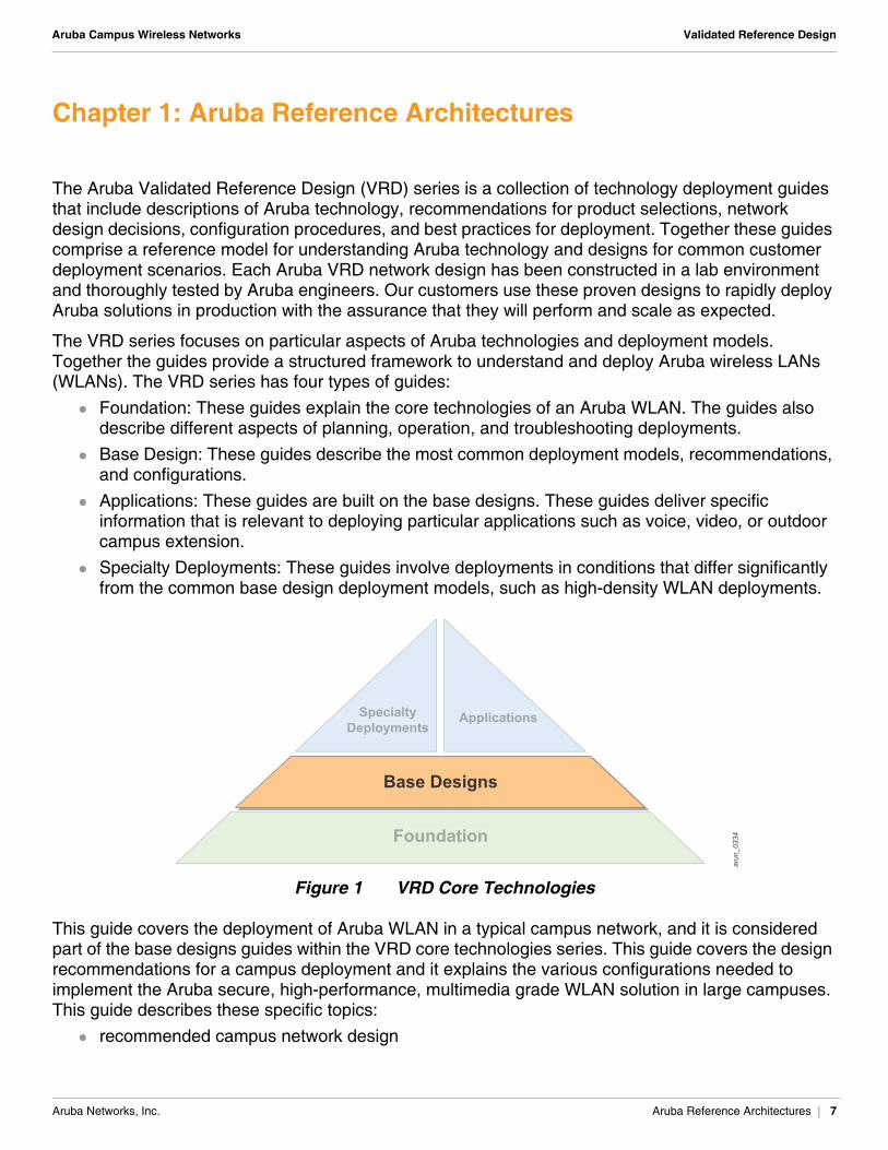
The VRD series focuses on particular aspects of Aruba technologies and deployment models. Together the guides provide a structured framework to understand and deploy Aruba wireless LANs (WLANs). The VRD series has four types of guides:
Foundation: These guides explain the core technologies of an Aruba WLAN. The guides also describe different aspects of planning, operation, and troubleshooting deployments.
Base Design: These guides describe the most common deployment models, recommendations, and configurations.
Applications: These guides are built on the base designs. These guides deliver specific information that is relevant to deploying particular applications such as voice, video, or outdoor campus extension.
Specialty Deployments: These guides involve deployments in conditions that differ significantly from the common base design deployment models, such as high-density WLAN deployments.
Figure 1 VRD Core Technologies
This guide covers the deployment of Aruba WLAN in a typical campus network, and it is considered part of the base designs guides within the VRD core technologies series. This guide covers the design recommendations for a campus deployment and it explains the various configurations needed to implement the Aruba secure, high-performance, multimedia grade WLAN solution in large campuses. This guide describes these specific topics:
recommended campus network design
arun_0334Foundation
Base Designs
SpecialtyDeployments
Applications
Aruba Networks, Inc. Aruba Reference Architectures | 7
Aruba Campus Wireless Networks Validated Reference Design
configuration of redundancy in campus deployments configuration of AP groups for client access and air monitors configuration of spectrum monitors (SMs) configuration of Layer 3 mobility configuration of control plane security (CPsec)
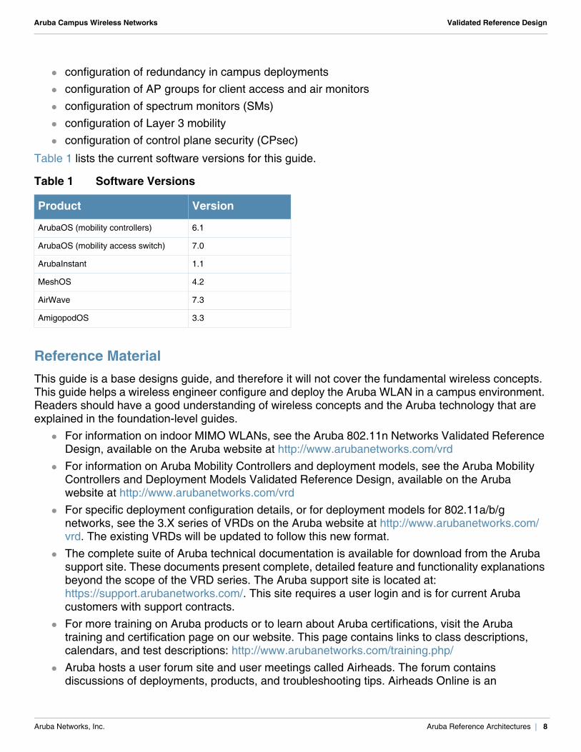
Table 1 lists the current software versions for this guide.
Reference MaterialThis guide is a base designs guide, and therefore it will not cover the fundamental wireless concepts. This guide helps a wireless engineer configure and deploy the Aruba WLAN in a campus environment. Readers should have a good understanding of wireless concepts and the Aruba technology that are explained in the foundation-level guides.
For information on indoor MIMO WLANs, see the Aruba 802.11n Networks Validated Reference Design, available on the Aruba website at http://www.arubanetworks.com/vrd
For information on Aruba Mobility Controllers and deployment models, see the Aruba Mobility Controllers and Deployment Models Validated Reference Design, available on the Aruba website at http://www.arubanetworks.com/vrd
For specific deployment configuration details, or for deployment models for 802.11a/b/g networks, see the 3.X series of VRDs on the Aruba website at http://www.arubanetworks.com/vrd. The existing VRDs will be updated to follow this new format.
The complete suite of Aruba technical documentation is available for download from the Aruba support site. These documents present complete, detailed feature and functionality explanations beyond the scope of the VRD series. The Aruba support site is located at: https://support.arubanetworks.com/. This site requires a user login and is for current Aruba customers with support contracts.
For more training on Aruba products or to learn about Aruba certifications, visit the Aruba training and certification page on our website. This page contains links to class descriptions, calendars, and test descriptions: http://www.arubanetworks.com/training.php/
Aruba hosts a user forum site and user meetings called Airheads. The forum contains discussions of deployments, products, and troubleshooting tips. Airheads Online is an
Table 1 Software Versions
Product Version
ArubaOS (mobility controllers) 6.1
ArubaOS (mobility access switch) 7.0
ArubaInstant 1.1
MeshOS 4.2
AirWave 7.3
AmigopodOS 3.3
Aruba Networks, Inc. Aruba Reference Architectures | 8
Aruba Campus Wireless Networks Validated Reference Design
invaluable resource that allows network administrators to interact with each other and Aruba experts. Announcements for Airheads in person meetings are also available on the site: http://airheads.arubanetworks.com/
The VRD series assumes a working knowledge of Wi-Fi®, and more specifically dependent AP, or controller based, architectures. For more information about wireless technology fundamentals, visit the Certified Wireless Network Professional (CWNP) site at http://www.cwnp.com/
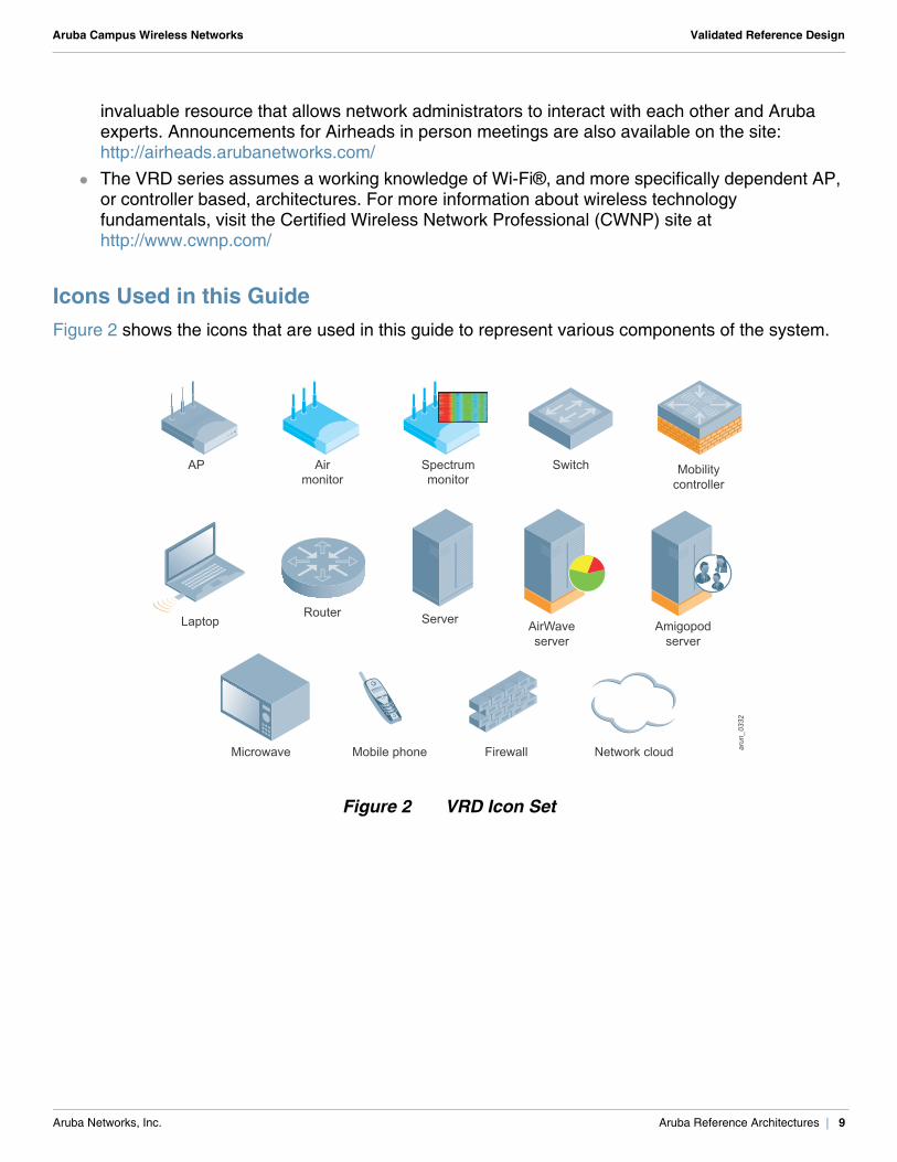
Icons Used in this GuideFigure 2 shows the icons that are used in this guide to represent various components of the system.
Figure 2 VRD Icon Set
Airmonitor
Microwave Mobile phone Firewall Network cloud
AP
Laptop
Spectrummonitor
Mobilitycontroller
Switch
RouterAirWaveserver
Server Amigopodserver
arun_0332
Aruba Networks, Inc. Aruba Reference Architectures | 9

Aruba Campus Wireless Networks Validated Reference Design
Aruba Networks, Inc. Aruba Reference Architectures | 10
Aruba Campus Wireless Networks Validated Reference Design
Chapter 2: Campus Deployments
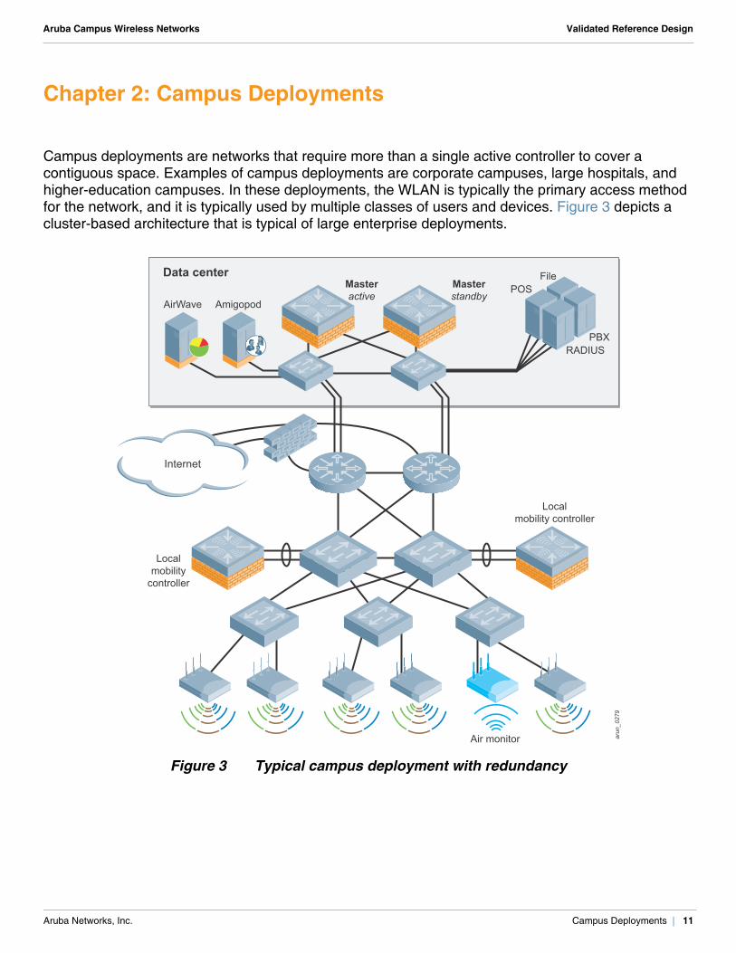
Campus deployments are networks that require more than a single active controller to cover a contiguous space. Examples of campus deployments are corporate campuses, large hospitals, and higher-education campuses. In these deployments, the WLAN is typically the primary access method for the network, and it is typically used by multiple classes of users and devices. Figure 3 depicts a cluster-based architecture that is typical of large enterprise deployments.
Figure 3 Typical campus deployment with redundancy
arun_0279
Air monitor
Internet
Localmobility
controller
Localmobility controller
POSFile
RADIUSPBX
Masterstandby
Data centerMasteractive
AirWave Amigopod
Aruba Networks, Inc. Campus Deployments | 11
Aruba Campus Wireless Networks Validated Reference Design
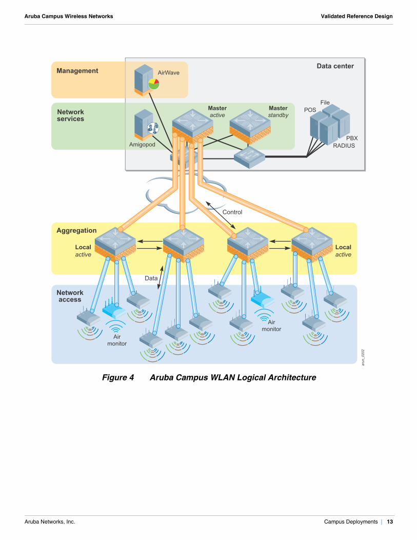
Aruba Campus WLAN Logical ArchitectureAruba WLAN has a logical four-tier operating model that consists of these four layers:
Management: The management layer consists of AirWave®. AirWave provides a single point of management for the WLAN, including reporting, heat maps, centralized configuration, and troubleshooting.
Network services: The network services layer consists of master mobility controllers and Amigopod. Amigopod provides secure and flexible visitor management services. The master controllers provide a control plane for the Aruba WLAN that spans the physical geography of the wired network. The control plane does not directly deal with user traffic or APs. Instead the control plane provides services such as whitelist coordination, valid AP lists, CPsec certificates, RFProtect™ coordination, and RADIUS or AAA proxy.
Aggregation: The aggregation layer is the interconnect point where the AP, air monitor (AM), and SM traffic aggregates. This layer provides a logical point for enforcement of roles and policies on centralized traffic that enters or exits the enterprise LAN.
Network access: The network access layer is comprised of APs, AMs, and SMs that work together with the aggregation layer controllers to overlay the Aruba WLAN.
Aruba Networks, Inc. Campus Deployments | 12
Aruba Campus Wireless Networks Validated Reference Design
Figure 4 Aruba Campus WLAN Logical Architecture
Retail_107
arun_0202
Airmonitor
Airmonitor
Control
Data
Localactive
Localactive
Masterstandby
Data center
MasteractiveNetwork
services
Management
Aggregation
Networkaccess
AirWave
POSFile
RADIUSPBX
Amigopod
Aruba Networks, Inc. Campus Deployments | 13
Aruba Campus Wireless Networks Validated Reference Design
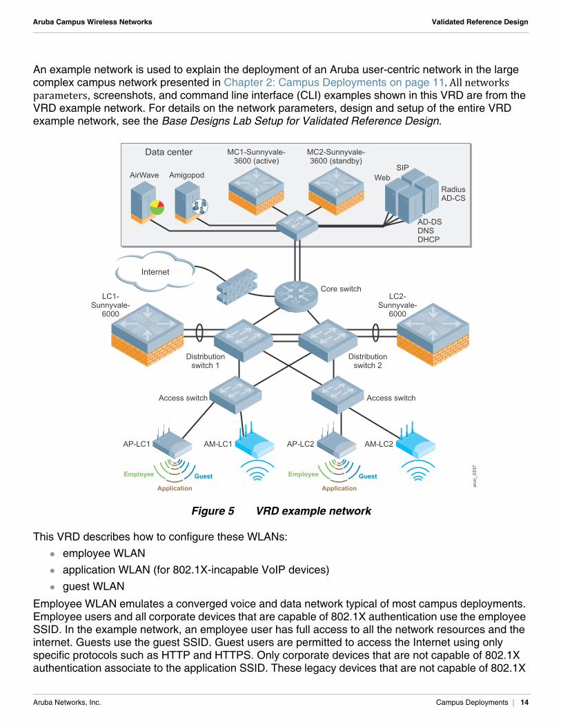
An example network is used to explain the deployment of an Aruba user-centric network in the large complex campus network presented in Chapter 2: Campus Deployments on page 11. All networks parameters, screenshots, and command line interface (CLI) examples shown in this VRD are from the VRD example network. For details on the network parameters, design and setup of the entire VRD example network, see the Base Designs Lab Setup for Validated Reference Design.
Figure 5 VRD example network
This VRD describes how to configure these WLANs: employee WLAN application WLAN (for 802.1X-incapable VoIP devices) guest WLAN
Employee WLAN emulates a converged voice and data network typical of most campus deployments. Employee users and all corporate devices that are capable of 802.1X authentication use the employee SSID. In the example network, an employee user has full access to all the network resources and the internet. Guests use the guest SSID. Guest users are permitted to access the Internet using only specific protocols such as HTTP and HTTPS. Only corporate devices that are not capable of 802.1X authentication associate to the application SSID. These legacy devices that are not capable of 802.1X
arun_0337
AM-LC1AP-LC1 AM-LC2AP-LC2
GuestEmployee
Application
GuestEmployee
Application
Internet
Data center MC1-Sunnyvale-3600 (active)
MC2-Sunnyvale-3600 (standby)
LC1-Sunnyvale-
6000
LC2-Sunnyvale-
6000
WebSIP
RadiusAD-CS
AD-DSDNSDHCP
Core switch
Distributionswitch 2
Access switchAccess switch
Distributionswitch 1
AirWave Amigopod
Aruba Networks, Inc. Campus Deployments | 14
Aruba Campus Wireless Networks Validated Reference Design
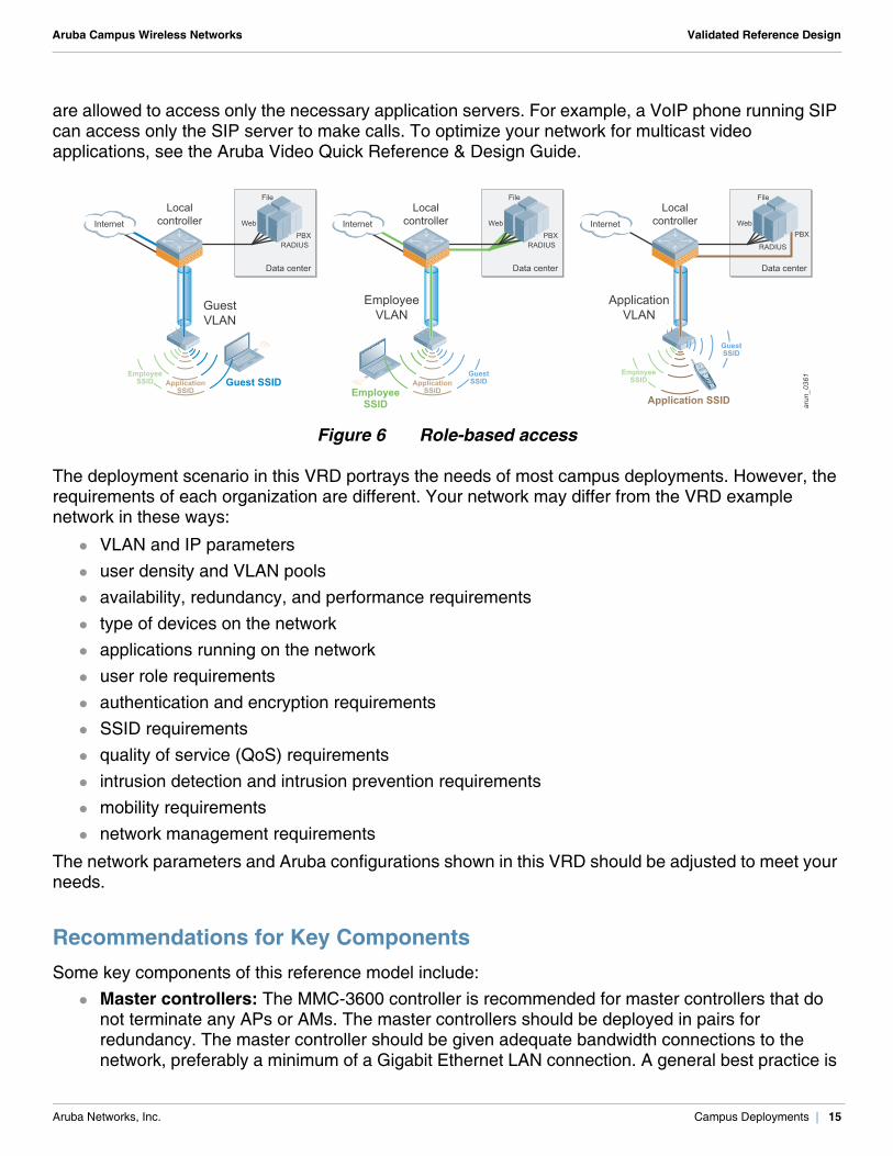
are allowed to access only the necessary application servers. For example, a VoIP phone running SIP can access only the SIP server to make calls. To optimize your network for multicast video applications, see the Aruba Video Quick Reference & Design Guide.
Figure 6 Role-based access
The deployment scenario in this VRD portrays the needs of most campus deployments. However, the requirements of each organization are different. Your network may differ from the VRD example network in these ways:
VLAN and IP parameters user density and VLAN pools availability, redundancy, and performance requirements type of devices on the network applications running on the network user role requirements authentication and encryption requirements SSID requirements quality of service (QoS) requirements intrusion detection and intrusion prevention requirements mobility requirements network management requirements
The network parameters and Aruba configurations shown in this VRD should be adjusted to meet your needs.
Recommendations for Key Components Some key components of this reference model include:
Master controllers: The MMC-3600 controller is recommended for master controllers that do not terminate any APs or AMs. The master controllers should be deployed in pairs for redundancy. The master controller should be given adequate bandwidth connections to the network, preferably a minimum of a Gigabit Ethernet LAN connection. A general best practice is
arun_0361
Application SSID
Web
File
RADIUSPBX
Data center
GuestVLAN
Guest SSIDEmployee
SSID ApplicationSSID
EmployeeVLAN
Web
File
RADIUSPBX
Data center
EmployeeSSID
GuestSSIDApplication
SSID
Localcontroller
Localcontroller
Localcontroller InternetInternetInternet Web
File
RADIUS
PBX
Data center
ApplicationVLAN
EmployeeSSID
GuestSSID
Aruba Networks, Inc. Campus Deployments | 15
Aruba Campus Wireless Networks Validated Reference Design
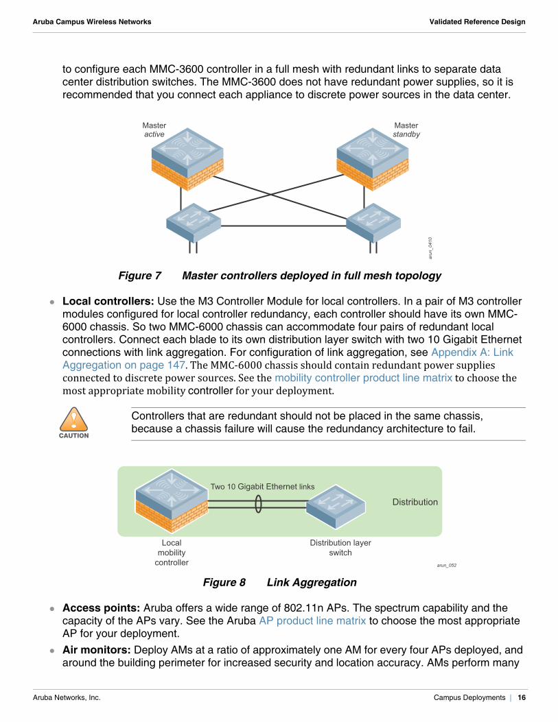
to configure each MMC-3600 controller in a full mesh with redundant links to separate data center distribution switches. The MMC-3600 does not have redundant power supplies, so it is recommended that you connect each appliance to discrete power sources in the data center.
Figure 7 Master controllers deployed in full mesh topology
Local controllers: Use the M3 Controller Module for local controllers. In a pair of M3 controller modules configured for local controller redundancy, each controller should have its own MMC-6000 chassis. So two MMC-6000 chassis can accommodate four pairs of redundant local controllers. Connect each blade to its own distribution layer switch with two 10 Gigabit Ethernet connections with link aggregation. For configuration of link aggregation, see Appendix A: Link Aggregation on page 147. The MMC-6000 chassis should contain redundant power supplies connected to discrete power sources. See the mobility controller product line matrix to choose the most appropriate mobility controller for your deployment.
Figure 8 Link Aggregation
Access points: Aruba offers a wide range of 802.11n APs. The spectrum capability and the capacity of the APs vary. See the Aruba AP product line matrix to choose the most appropriate AP for your deployment.
Air monitors: Deploy AMs at a ratio of approximately one AM for every four APs deployed, and around the building perimeter for increased security and location accuracy. AMs perform many
!CAUTION
Controllers that are redundant should not be placed in the same chassis, because a chassis failure will cause the redundancy architecture to fail.
arun_0410
Masterstandby
Masteractive
arun_052
Localmobility
controller
Distribution layerswitch
Two 10 Gigabit Ethernet links
Distribution
Aruba Networks, Inc. Campus Deployments | 16
Aruba Campus Wireless Networks Validated Reference Design
of the intrusion detection system (IDS) duties for the network, including rogue AP containment. AMs help to form accurate heat maps that display graphical RF data. Aruba considers dedicated AMs to be a best practice for security because they provide full-time surveillance of the air. Use the AP-105 as AMs, because these are dual-radio APs with full spectrum analysis support. For details on the spectrum capabilities of all the Aruba APs, see the Aruba AP product line matrix.
Aruba Networks, Inc. Campus Deployments | 17

Aruba Campus Wireless Networks Validated Reference Design
Aruba Networks, Inc. Campus Deployments | 18
Aruba Campus Wireless Networks Validated Reference Design
Chapter 3: Master/Local Operation
Large campus deployments normally involve more than two controllers. When you have more than a single pair of controllers, change control and network consistency can become an issue. To solve this management scalability issue, Aruba Mobility Controllers can be deployed in clusters that consist of a master and one or more local controllers. This design is the recommended model when two or more controllers exist in the same network. This design is depicted in this VRD.
In an Aruba network that uses a master/local design, configuration is performed only on the master and it is pushed down to the locals.
Local controllers reside at the aggregation layer of the Aruba overlay architecture. They handle AP termination, user authentication, and policy enforcement. When you configure any local controller, you must know the IP address of the master and the pre-shared key (PSK) that was used to encrypt communication between the controllers. The control channel between all Aruba controllers is protected by an IP Security (IPsec) connection. For more details on the functions and responsibilities of master and local mobility controllers in Aruba architecture, see the Aruba Mobility Controllers and Deployment Models Validated Reference Design.
Controller LicensesThe ArubaOS™ base operating system contains many features and extensive functionality for the enterprise WLAN network. Aruba uses a licensing mechanism to enable the additional features and to enable AP capacity on controllers. The controller licensing depends on the user density and the features needed to operate and secure your network. For more details about Aruba licenses, see Aruba Mobility Controllers and Deployment Models Validated Reference Design.
N O T E
In a large campus WLAN that has separate network services and aggregation layers, APs and AMs should never terminate on the master controller. APs and AMs should terminate only on the local controller. With this configuration, if the master becomes unreachable or unavailable and no standby master has been configured, the network continues to operate as expected, except for certain operations. You cannot perform configuration, RF visualization, or location services until connection to the master controller is restored. The master controller is needed to perform configuration and reporting, but it is not a single point of failure in the network.
N O T E
The controllers have a preconfigured key at first boot. Change this key after the first boot so that the operation of the master/local cluster is secure.
Aruba Networks, Inc. Master/Local Operation | 19
Aruba Campus Wireless Networks Validated Reference Design
Licensing Master Mobility Controllers
The master mobility controller must manage the functionality for all other platforms, so the master must have the same license types as the local mobility controllers. Licensing unlocks the configuration capabilities on the system. However, the master does not terminate APs or devices, so the master can be licensed at a much lower level than the local mobility controller.
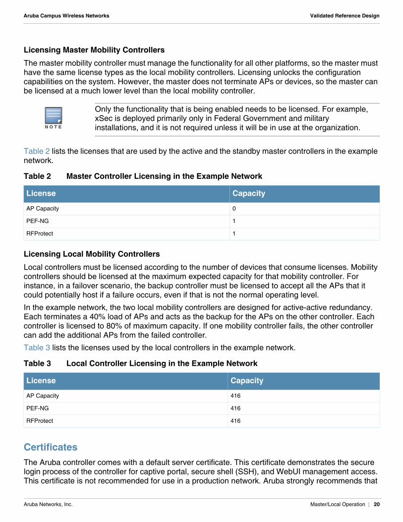
Table 2 lists the licenses that are used by the active and the standby master controllers in the example network.
Licensing Local Mobility Controllers
Local controllers must be licensed according to the number of devices that consume licenses. Mobility controllers should be licensed at the maximum expected capacity for that mobility controller. For instance, in a failover scenario, the backup controller must be licensed to accept all the APs that it could potentially host if a failure occurs, even if that is not the normal operating level.
In the example network, the two local mobility controllers are designed for active-active redundancy. Each terminates a 40% load of APs and acts as the backup for the APs on the other controller. Each controller is licensed to 80% of maximum capacity. If one mobility controller fails, the other controller can add the additional APs from the failed controller.
Table 3 lists the licenses used by the local controllers in the example network.
CertificatesThe Aruba controller comes with a default server certificate. This certificate demonstrates the secure login process of the controller for captive portal, secure shell (SSH), and WebUI management access. This certificate is not recommended for use in a production network. Aruba strongly recommends that
N O T E
Only the functionality that is being enabled needs to be licensed. For example, xSec is deployed primarily only in Federal Government and military installations, and it is not required unless it will be in use at the organization.
Table 2 Master Controller Licensing in the Example Network
License Capacity
AP Capacity 0
PEF-NG 1
RFProtect 1
Table 3 Local Controller Licensing in the Example Network
License Capacity
AP Capacity 416
PEF-NG 416
RFProtect 416
Aruba Networks, Inc. Master/Local Operation | 20
Aruba Campus Wireless Networks Validated Reference Design
you replace this certificate with a unique certificate that is issued to the organization or its domain by a trusted certificate authority (CA).
To receive a custom certificate from a trusted CA, generate a Certificate Signing Request (CSR) on the controller and submit it to the CA. After you receive the digitally signed certificate from the CA, import it to the controller. For more details about generating the CSR and importing certificates, see “Managing Certificates” in the ArubaOS 6.1 User Guide available on the Aruba support site.
Aruba Networks, Inc. Master/Local Operation | 21

Aruba Campus Wireless Networks Validated Reference Design
Aruba Networks, Inc. Master/Local Operation | 22
Aruba Campus Wireless Networks Validated Reference Design
Chapter 4: VLAN Design and Recommendations
On an Aruba controller at the aggregation layer, VLANs are used in two logically different places: the access side of the controller where the APs terminate their GRE tunnels the user access side
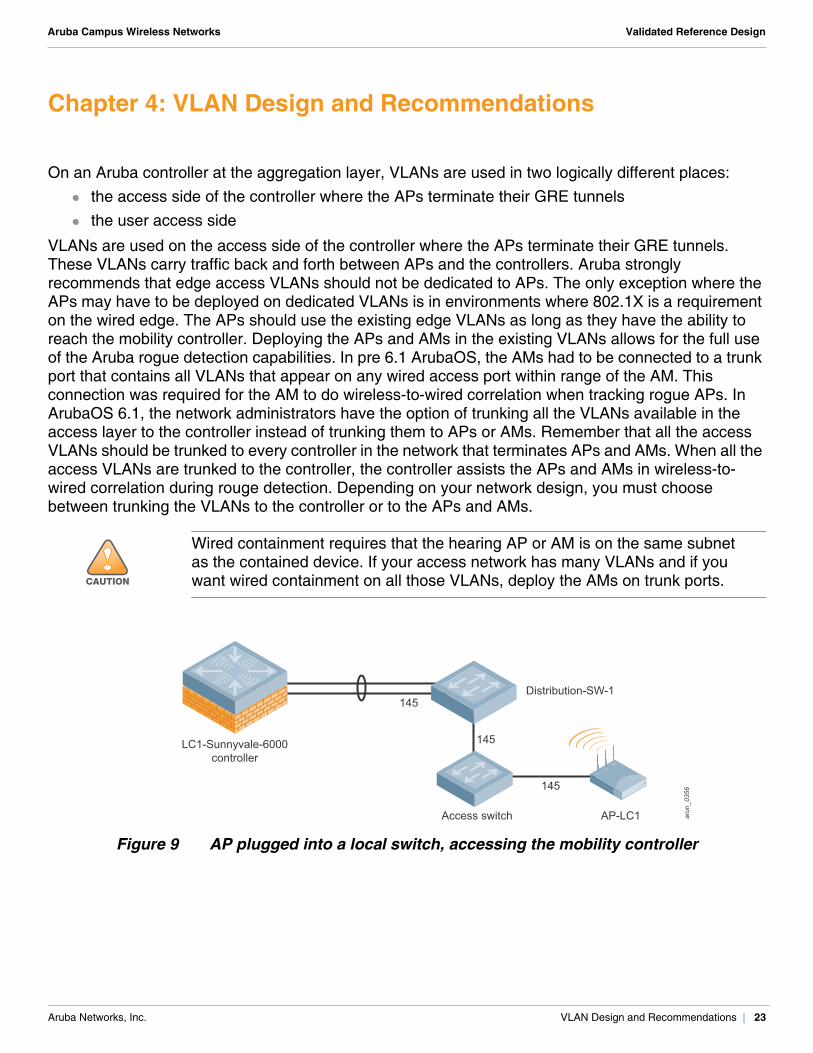
VLANs are used on the access side of the controller where the APs terminate their GRE tunnels. These VLANs carry traffic back and forth between APs and the controllers. Aruba strongly recommends that edge access VLANs should not be dedicated to APs. The only exception where the APs may have to be deployed on dedicated VLANs is in environments where 802.1X is a requirement on the wired edge. The APs should use the existing edge VLANs as long as they have the ability to reach the mobility controller. Deploying the APs and AMs in the existing VLANs allows for the full use of the Aruba rogue detection capabilities. In pre 6.1 ArubaOS, the AMs had to be connected to a trunk port that contains all VLANs that appear on any wired access port within range of the AM. This connection was required for the AM to do wireless-to-wired correlation when tracking rogue APs. In ArubaOS 6.1, the network administrators have the option of trunking all the VLANs available in the access layer to the controller instead of trunking them to APs or AMs. Remember that all the access VLANs should be trunked to every controller in the network that terminates APs and AMs. When all the access VLANs are trunked to the controller, the controller assists the APs and AMs in wireless-to-wired correlation during rouge detection. Depending on your network design, you must choose between trunking the VLANs to the controller or to the APs and AMs.
Figure 9 AP plugged into a local switch, accessing the mobility controller
!CAUTION
Wired containment requires that the hearing AP or AM is on the same subnet as the contained device. If your access network has many VLANs and if you want wired containment on all those VLANs, deploy the AMs on trunk ports.
arun_0356
LC1-Sunnyvale-6000controller
145
AP-LC1Access switch
Distribution-SW-1
145
145
Aruba Networks, Inc. VLAN Design and Recommendations | 23
Aruba Campus Wireless Networks Validated Reference Design
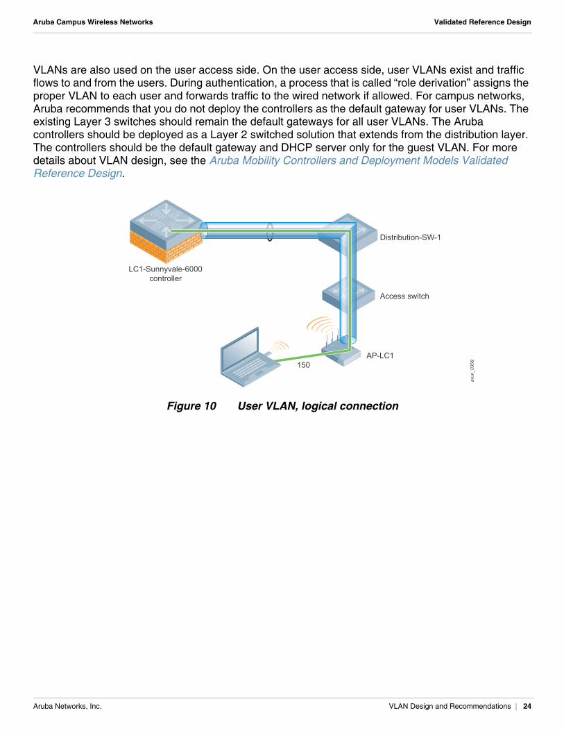
VLANs are also used on the user access side. On the user access side, user VLANs exist and traffic flows to and from the users. During authentication, a process that is called “role derivation” assigns the proper VLAN to each user and forwards traffic to the wired network if allowed. For campus networks, Aruba recommends that you do not deploy the controllers as the default gateway for user VLANs. The existing Layer 3 switches should remain the default gateways for all user VLANs. The Aruba controllers should be deployed as a Layer 2 switched solution that extends from the distribution layer. The controllers should be the default gateway and DHCP server only for the guest VLAN. For more details about VLAN design, see the Aruba Mobility Controllers and Deployment Models Validated Reference Design.
Figure 10 User VLAN, logical connection
arun_0358
LC1-Sunnyvale-6000controller
150AP-LC1
Access switch
Distribution-SW-1
Aruba Networks, Inc. VLAN Design and Recommendations | 24
Aruba Campus Wireless Networks Validated Reference Design
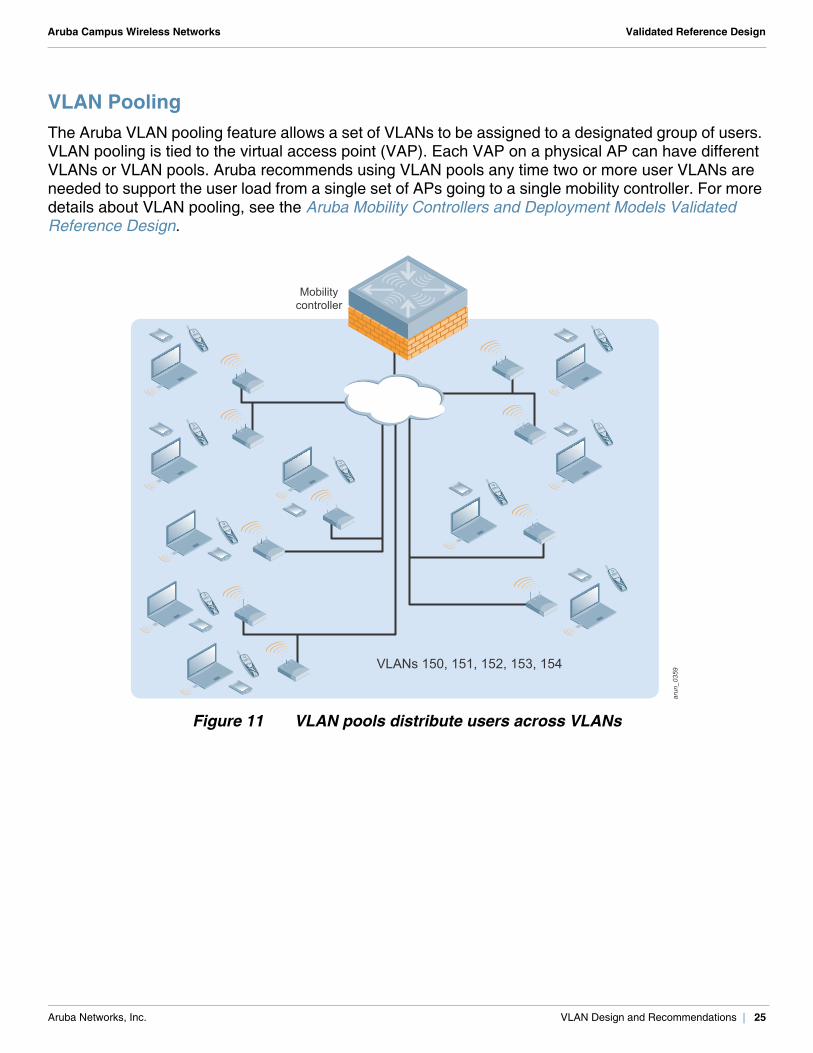
VLAN PoolingThe Aruba VLAN pooling feature allows a set of VLANs to be assigned to a designated group of users. VLAN pooling is tied to the virtual access point (VAP). Each VAP on a physical AP can have different VLANs or VLAN pools. Aruba recommends using VLAN pools any time two or more user VLANs are needed to support the user load from a single set of APs going to a single mobility controller. For more details about VLAN pooling, see the Aruba Mobility Controllers and Deployment Models Validated Reference Design.
Figure 11 VLAN pools distribute users across VLANs
arun_049arun_0359VLANs 150, 151, 152, 153, 154
Mobilitycontroller
Aruba Networks, Inc. VLAN Design and Recommendations | 25
Aruba Campus Wireless Networks Validated Reference Design
To determine which pool to put the user into, the user MAC address is run through a hash algorithm. The output of this algorithm places the user into one of the VLANs in the pool and ensures that the user is always placed into the same pool during a roaming event. As the user associates with the next AP, the address is hashed. The user is again placed into the same VLAN on the new AP, because the hash algorithm generates the same output as before. The user can continue to use their existing IP address with no break in their user sessions.
A single VLAN or a VLAN pool can be named by the administrator. The VLAN names are global, but the VLAN IDs associated with those names are local to the controller. The VLAN names are configured globally in the master controller and are synchronized to the local controllers. The VLAN IDs that are associated to a particular VLAN name are defined in the local controllers and can vary across the controllers.
The example network uses 10 VLANs (VLAN 150-159) split into these two pools: pool-7 is used by the employee and application VAPs in the AP group that uses the virtual IP
(VIP) of Virtual Router Redundancy Protocol (VRRP) instance 7 as the local management switch (LMS) IP.
pool-8 is used by the employee and application VAPs in the AP group that uses the VIP of VRRP instance 8 as the LMS IP.
N O T E
The hashing algorithm does not place users into the available pool of VLANs in a round-robin method. Ten clients that join a WLAN are not load balanced equally among the VLANs. Instead, the distribution is based on the output of the hash. One VLAN might have more users than the others. For example, consider 150 clients that join a WLAN with just two VLANs in the pool and with 80 addresses per VLAN available for clients. Based on the output of the hashing algorithm, 80 clients are placed in one VLAN and 70 in the other. When the 151st client joins, the output of the hash might place the client in the VLAN whose scope of 80 addresses has already exhausted. The result is that the client cannot obtain an IP. To avoid such a rare situation, the network administrator should design pools with sufficient number of user VLANs and DHCP scopes to accommodate the user density.
!CAUTION
During VLAN pooling, the controller places the user into a particular VLAN based on the hash calculated using the media access control (MAC) address of the client. Hence, the VLAN obtained as a result of the hashing algorithm cannot be predicted beforehand. In networks that use VLAN pooling, the clients with static IP addressing will not work because the statically assigned VLAN and the VLAN obtained by the controller after running the hash can be different. Aruba recommends that VLAN pooling and static IP addressing should never be used simultaneously within a single SSID.
Aruba Networks, Inc. VLAN Design and Recommendations | 26
Aruba Campus Wireless Networks Validated Reference Design
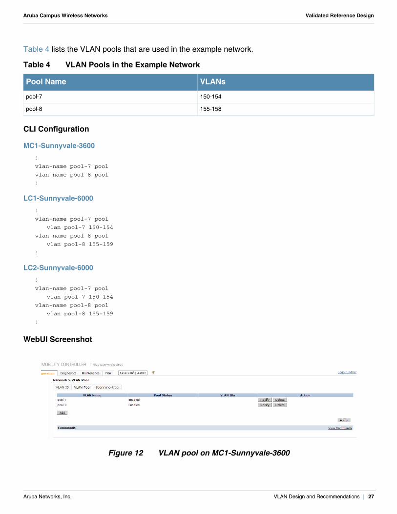
Table 4 lists the VLAN pools that are used in the example network.
CLI Configuration
MC1-Sunnyvale-3600!
vlan-name pool-7 pool
vlan-name pool-8 pool
!
LC1-Sunnyvale-6000!
vlan-name pool-7 pool
vlan pool-7 150-154
vlan-name pool-8 pool
vlan pool-8 155-159
!
LC2-Sunnyvale-6000!
vlan-name pool-7 pool
vlan pool-7 150-154
vlan-name pool-8 pool
vlan pool-8 155-159
!
WebUI Screenshot
Figure 12 VLAN pool on MC1-Sunnyvale-3600
Table 4 VLAN Pools in the Example Network
Pool Name VLANs
pool-7 150-154
pool-8 155-158
Aruba Networks, Inc. VLAN Design and Recommendations | 27
Aruba Campus Wireless Networks Validated Reference Design
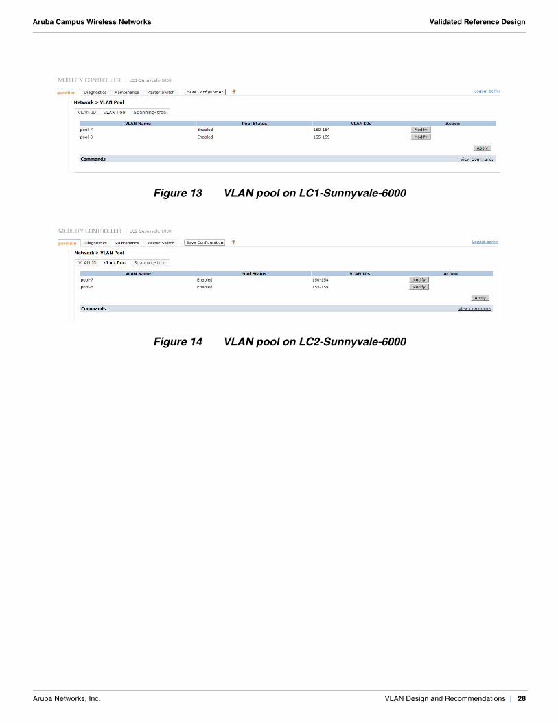
Figure 13 VLAN pool on LC1-Sunnyvale-6000
Figure 14 VLAN pool on LC2-Sunnyvale-6000
Aruba Networks, Inc. VLAN Design and Recommendations | 28
Aruba Campus Wireless Networks Validated Reference Design
Chapter 5: Redundancy
Aruba offers several redundancy models for master controller redundancy and local control redundancy. The Aruba redundancy solutions can be implemented using VRRP or backup LMS IP. Use VRRP, which operates at Layer 2, for redundancy whenever possible. For more details about the various redundancy models and when to use backup LMS IP, see Aruba Mobility Controllers and Deployment Models Validated Reference Design.
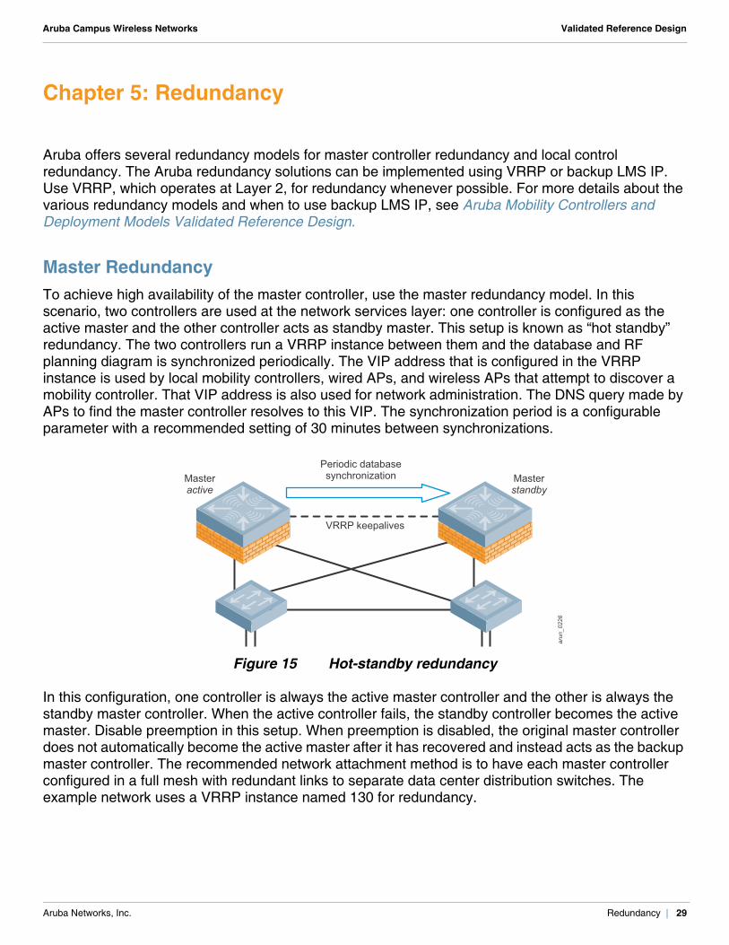
Master RedundancyTo achieve high availability of the master controller, use the master redundancy model. In this scenario, two controllers are used at the network services layer: one controller is configured as the active master and the other controller acts as standby master. This setup is known as “hot standby” redundancy. The two controllers run a VRRP instance between them and the database and RF planning diagram is synchronized periodically. The VIP address that is configured in the VRRP instance is used by local mobility controllers, wired APs, and wireless APs that attempt to discover a mobility controller. That VIP address is also used for network administration. The DNS query made by APs to find the master controller resolves to this VIP. The synchronization period is a configurable parameter with a recommended setting of 30 minutes between synchronizations.
Figure 15 Hot-standby redundancy
In this configuration, one controller is always the active master controller and the other is always the standby master controller. When the active controller fails, the standby controller becomes the active master. Disable preemption in this setup. When preemption is disabled, the original master controller does not automatically become the active master after it has recovered and instead acts as the backup master controller. The recommended network attachment method is to have each master controller configured in a full mesh with redundant links to separate data center distribution switches. The example network uses a VRRP instance named 130 for redundancy.
arun_0226
Masterstandby
VRRP keepalives
Periodic databasesynchronizationMaster
active
Aruba Networks, Inc. Redundancy | 29
Aruba Campus Wireless Networks Validated Reference Design
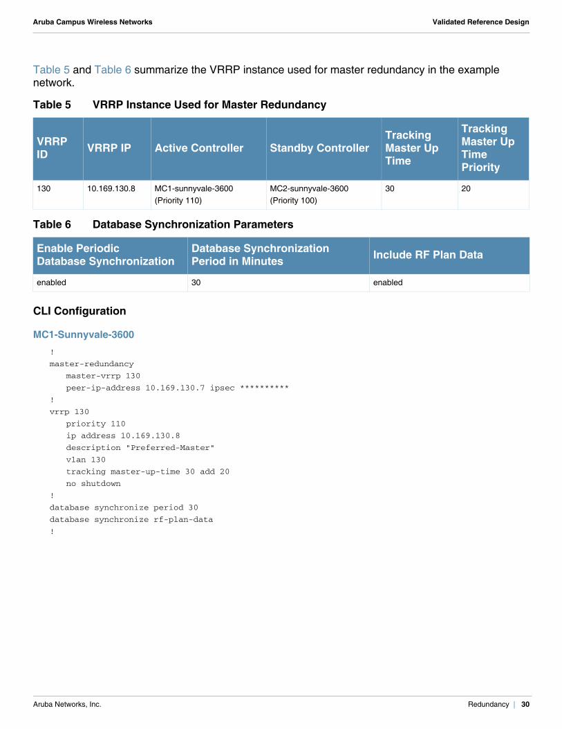
Table 5 and Table 6 summarize the VRRP instance used for master redundancy in the example network.
CLI Configuration
MC1-Sunnyvale-3600!
master-redundancy
master-vrrp 130
peer-ip-address 10.169.130.7 ipsec **********
!
vrrp 130
priority 110
ip address 10.169.130.8
description "Preferred-Master"
vlan 130
tracking master-up-time 30 add 20
no shutdown
!
database synchronize period 30
database synchronize rf-plan-data
!
Table 5 VRRP Instance Used for Master Redundancy
VRRP ID VRRP IP Active Controller Standby Controller
Tracking Master Up Time
Tracking Master Up Time Priority
130 10.169.130.8 MC1-sunnyvale-3600(Priority 110)
MC2-sunnyvale-3600(Priority 100)
30 20
Table 6 Database Synchronization Parameters
Enable Periodic Database Synchronization
Database Synchronization Period in Minutes Include RF Plan Data
enabled 30 enabled
Aruba Networks, Inc. Redundancy | 30
Aruba Campus Wireless Networks Validated Reference Design
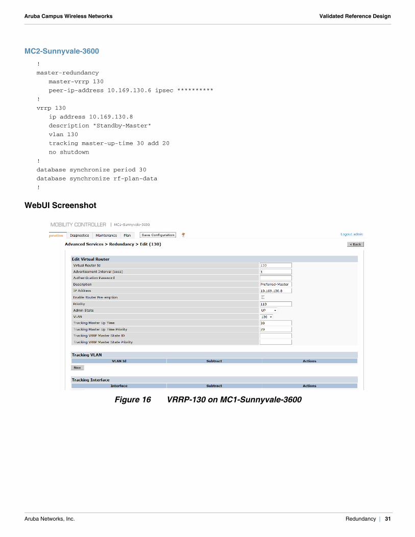
MC2-Sunnyvale-3600!
master-redundancy
master-vrrp 130
peer-ip-address 10.169.130.6 ipsec **********
!
vrrp 130
ip address 10.169.130.8
description "Standby-Master"
vlan 130
tracking master-up-time 30 add 20
no shutdown
!
database synchronize period 30
database synchronize rf-plan-data
!
WebUI Screenshot
Figure 16 VRRP-130 on MC1-Sunnyvale-3600
Aruba Networks, Inc. Redundancy | 31
Aruba Campus Wireless Networks Validated Reference Design
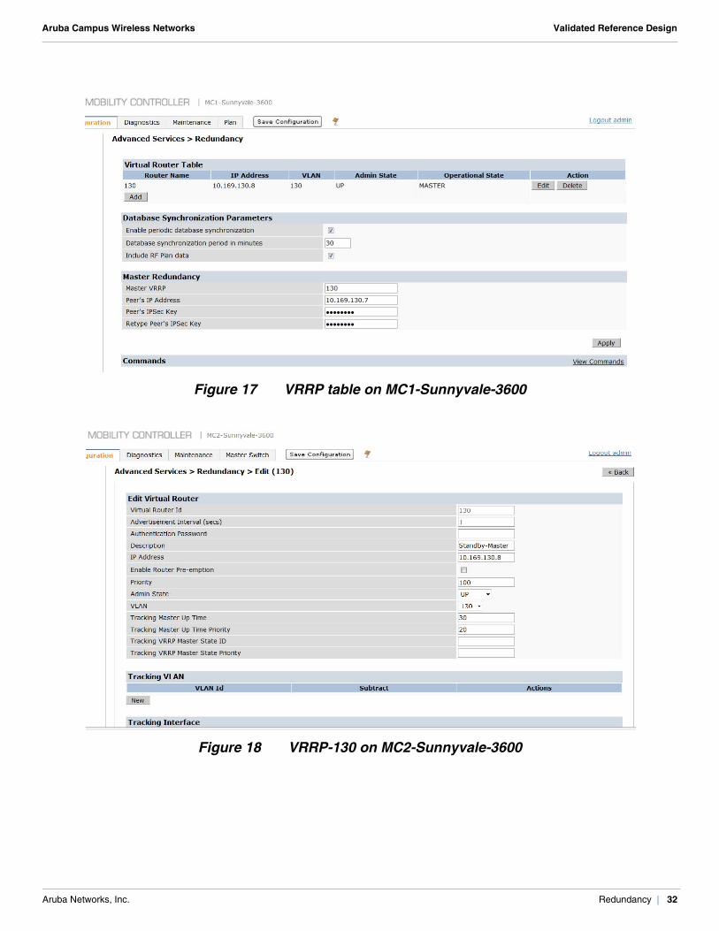
Figure 17 VRRP table on MC1-Sunnyvale-3600
Figure 18 VRRP-130 on MC2-Sunnyvale-3600
Aruba Networks, Inc. Redundancy | 32
Aruba Campus Wireless Networks Validated Reference Design
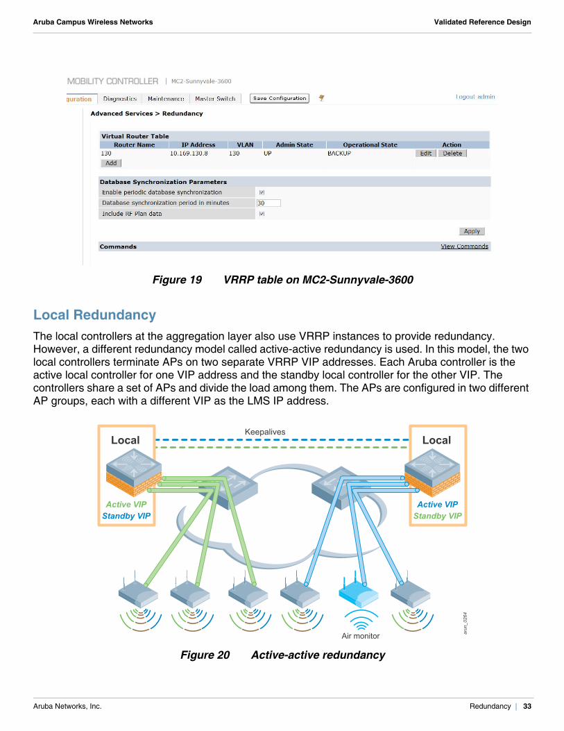
Figure 19 VRRP table on MC2-Sunnyvale-3600
Local RedundancyThe local controllers at the aggregation layer also use VRRP instances to provide redundancy. However, a different redundancy model called active-active redundancy is used. In this model, the two local controllers terminate APs on two separate VRRP VIP addresses. Each Aruba controller is the active local controller for one VIP address and the standby local controller for the other VIP. The controllers share a set of APs and divide the load among them. The APs are configured in two different AP groups, each with a different VIP as the LMS IP address.
Figure 20 Active-active redundancy
arun_044
arun_0264
Air monitor
Keepalives
Active VIPStandby VIP
Local
Active VIPStandby VIP
Local
Aruba Networks, Inc. Redundancy | 33
Aruba Campus Wireless Networks Validated Reference Design
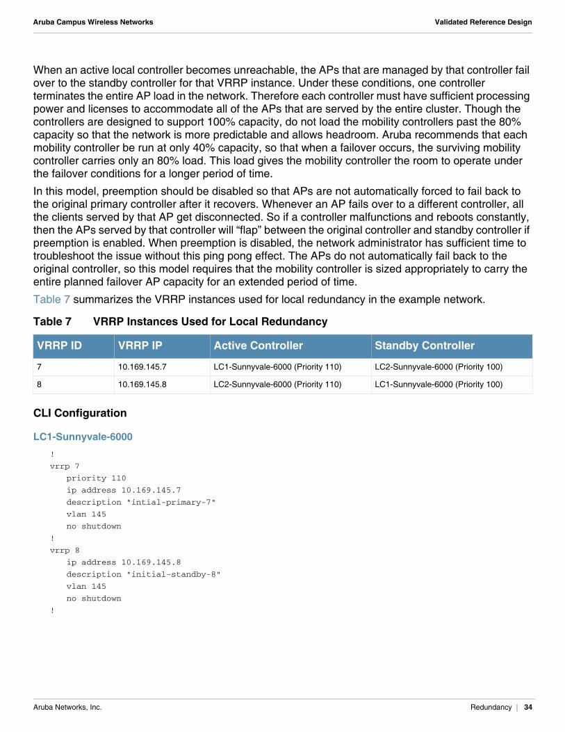
When an active local controller becomes unreachable, the APs that are managed by that controller fail over to the standby controller for that VRRP instance. Under these conditions, one controller terminates the entire AP load in the network. Therefore each controller must have sufficient processing power and licenses to accommodate all of the APs that are served by the entire cluster. Though the controllers are designed to support 100% capacity, do not load the mobility controllers past the 80% capacity so that the network is more predictable and allows headroom. Aruba recommends that each mobility controller be run at only 40% capacity, so that when a failover occurs, the surviving mobility controller carries only an 80% load. This load gives the mobility controller the room to operate under the failover conditions for a longer period of time.
In this model, preemption should be disabled so that APs are not automatically forced to fail back to the original primary controller after it recovers. Whenever an AP fails over to a different controller, all the clients served by that AP get disconnected. So if a controller malfunctions and reboots constantly, then the APs served by that controller will “flap” between the original controller and standby controller if preemption is enabled. When preemption is disabled, the network administrator has sufficient time to troubleshoot the issue without this ping pong effect. The APs do not automatically fail back to the original controller, so this model requires that the mobility controller is sized appropriately to carry the entire planned failover AP capacity for an extended period of time.
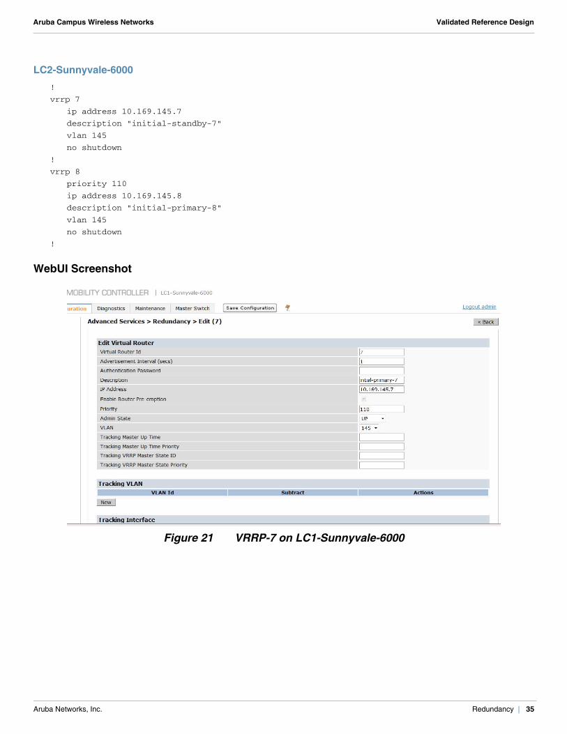
Table 7 summarizes the VRRP instances used for local redundancy in the example network.
CLI Configuration
LC1-Sunnyvale-6000!
vrrp 7
priority 110
ip address 10.169.145.7
description "intial-primary-7"
vlan 145
no shutdown
!
vrrp 8
ip address 10.169.145.8
description "initial-standby-8"
vlan 145
no shutdown
!
Table 7 VRRP Instances Used for Local Redundancy
VRRP ID VRRP IP Active Controller Standby Controller
7 10.169.145.7 LC1-Sunnyvale-6000 (Priority 110) LC2-Sunnyvale-6000 (Priority 100)
8 10.169.145.8 LC2-Sunnyvale-6000 (Priority 110) LC1-Sunnyvale-6000 (Priority 100)
Aruba Networks, Inc. Redundancy | 34
Aruba Campus Wireless Networks Validated Reference Design
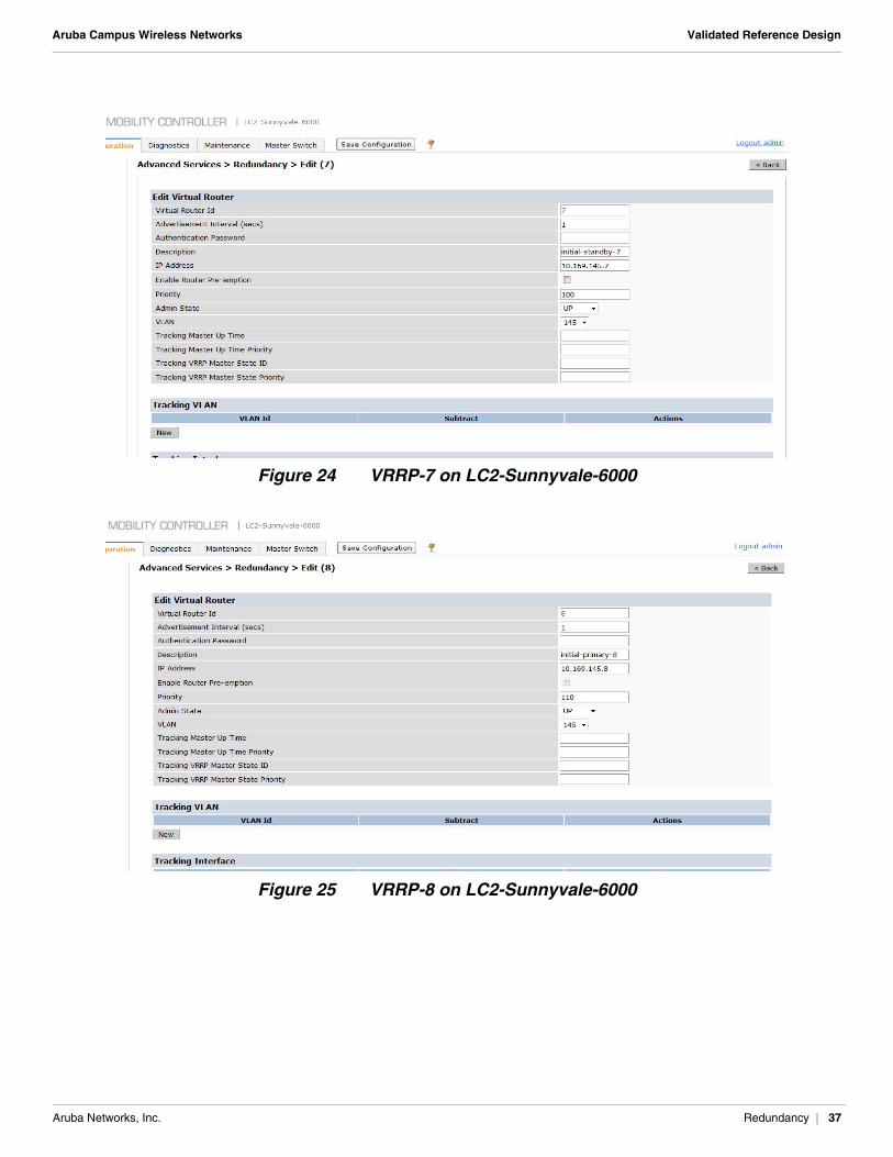
LC2-Sunnyvale-6000!
vrrp 7
ip address 10.169.145.7
description "initial-standby-7"
vlan 145
no shutdown
!
vrrp 8
priority 110
ip address 10.169.145.8
description "initial-primary-8"
vlan 145
no shutdown
!
WebUI Screenshot
Figure 21 VRRP-7 on LC1-Sunnyvale-6000
Aruba Networks, Inc. Redundancy | 35
Aruba Campus Wireless Networks Validated Reference Design
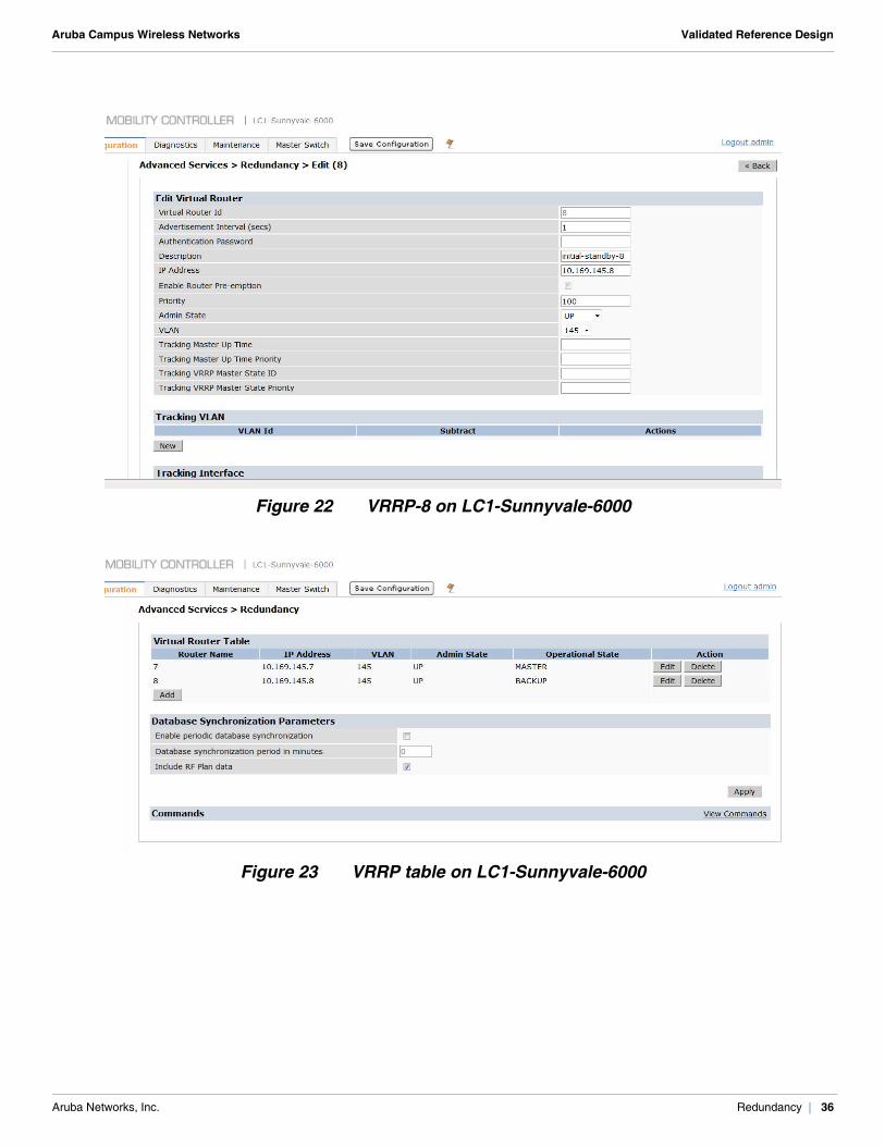
Figure 22 VRRP-8 on LC1-Sunnyvale-6000
Figure 23 VRRP table on LC1-Sunnyvale-6000
Aruba Networks, Inc. Redundancy | 36
Aruba Campus Wireless Networks Validated Reference Design
Figure 24 VRRP-7 on LC2-Sunnyvale-6000
Figure 25 VRRP-8 on LC2-Sunnyvale-6000
Aruba Networks, Inc. Redundancy | 37
Aruba Campus Wireless Networks Validated Reference Design
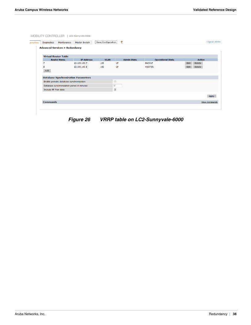
Figure 26 VRRP table on LC2-Sunnyvale-6000
Aruba Networks, Inc. Redundancy | 38
Aruba Campus Wireless Networks Validated Reference Design
Chapter 6: User Roles, Profiles, and AP Groups
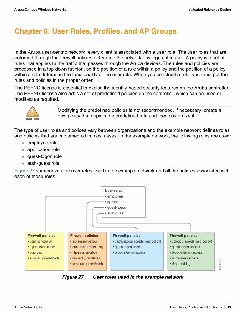
In the Aruba user-centric network, every client is associated with a user role. The user roles that are enforced through the firewall policies determine the network privileges of a user. A policy is a set of rules that applies to the traffic that passes through the Aruba devices. The rules and policies are processed in a top-down fashion, so the position of a rule within a policy and the position of a policy within a role determine the functionality of the user role. When you construct a role, you must put the rules and policies in the proper order.
The PEFNG license is essential to exploit the identity-based security features on the Aruba controller. The PEFNG license also adds a set of predefined policies on the controller, which can be used or modified as required.
The type of user roles and polices vary between organizations and the example network defines roles and policies that are implemented in most cases. In the example network, the following roles are used:
employee role application role guest-logon role auth-guest role
Figure 27 summarizes the user roles used in the example network and all the policies associated with each of those roles.
Figure 27 User roles used in the example network
!CAUTION
Modifying the predefined policies is not recommended. If necessary, create a new policy that depicts the predefined rule and then customize it.
arun_0367
Firewall policies• common-policy• sip-session-allow• ocs-lync• allowall (predefined)
Firewall policies• sip-session-allow• dhcp-acl (predefined)• tftp-session-allow• dns-acl (predefined)• icmp-acl (predefined)
Firewall policies• cplogout (predefined policy)• guest-logon-access• block-internal-access• auth-guest-access• drop-and-log
Firewall policies• captiveportal (predefined policy)• guest-logon-access• block-internal-access
User roles• employee• application• guest-logon• auth-guest
Aruba Networks, Inc. User Roles, Profiles, and AP Groups | 39
Aruba Campus Wireless Networks Validated Reference Design
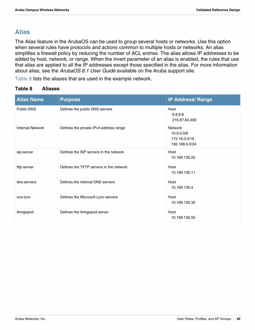
AliasThe Alias feature in the ArubaOS can be used to group several hosts or networks. Use this option when several rules have protocols and actions common to multiple hosts or networks. An alias simplifies a firewall policy by reducing the number of ACL entries. The alias allows IP addresses to be added by host, network, or range. When the invert parameter of an alias is enabled, the rules that use that alias are applied to all the IP addresses except those specified in the alias. For more information about alias, see the ArubaOS 6.1 User Guide available on the Aruba support site.
Table 8 lists the aliases that are used in the example network.
Table 8 Aliases
Alias Name Purpose IP Address/ Range
Public-DNS Defines the public DNS servers Host 8.8.8.8 216.87.84.209
Internal-Network Defines the private IPv4 address range Network 10.0.0.0/8 172.16.0.0/16 192.168.0.0/24
sip-server Defines the SIP servers in the network Host 10.169.130.20
tftp-server Defines the TFTP servers in the network Host 10.169.130.11
dns-servers Defines the internal DNS servers Host 10.169.130.4
ocs-lync Defines the Microsoft Lync servers Host 10.169.130.35
Amigopod Defines the Amigopod server Host 10.169.130.50
Aruba Networks, Inc. User Roles, Profiles, and AP Groups | 40
Aruba Campus Wireless Networks Validated Reference Design
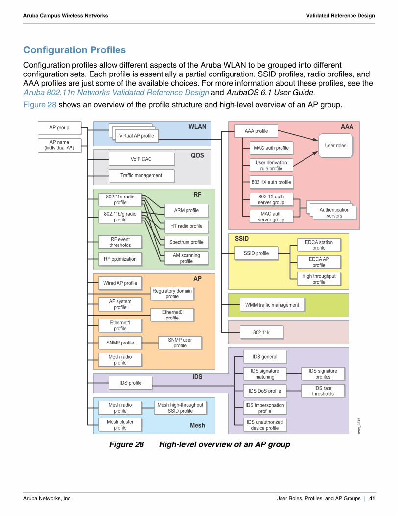
Configuration ProfilesConfiguration profiles allow different aspects of the Aruba WLAN to be grouped into different configuration sets. Each profile is essentially a partial configuration. SSID profiles, radio profiles, and AAA profiles are just some of the available choices. For more information about these profiles, see the Aruba 802.11n Networks Validated Reference Design and ArubaOS 6.1 User Guide.
Figure 28 shows an overview of the profile structure and high-level overview of an AP group.
Figure 28 High-level overview of an AP group
arun_0344
IDS profile
IDS unauthorizeddevice profile
IDS DoS profile
IDS signaturematching
IDS ratethresholds
IDS signatureprofiles
IDS general
AP name(individual AP)
AP group WLAN
QOS
AAA
IDS
IDS impersonationprofile
User roles
User derivationrule profile
802.1X auth profile
MAC authserver group
MAC auth profile
802.1X authserver group
AAA profile
SSID
Mesh
SSID profileEDCA AP
profile
EDCA stationprofile
High throughputprofile
VoIP CAC
Virtual AP profile
Authenticationservers
Traffic management
802.11k
WMM traffic management
RF
RF optimization
RF eventthresholds
802.11a radioprofile
802.11b/g radioprofile
ARM profile
HT radio profile
Spectrum profile
AM scanningprofile
Mesh radioprofile
AP
Ethernet1profile
AP systemprofile
Wired AP profile
SNMP profile SNMP userprofile
Mesh clusterprofile
Mesh radioprofile
Mesh high-throughputSSID profile
Regulatory domainprofile
Ethernet0profile
Aruba Networks, Inc. User Roles, Profiles, and AP Groups | 41
Aruba Campus Wireless Networks Validated Reference Design
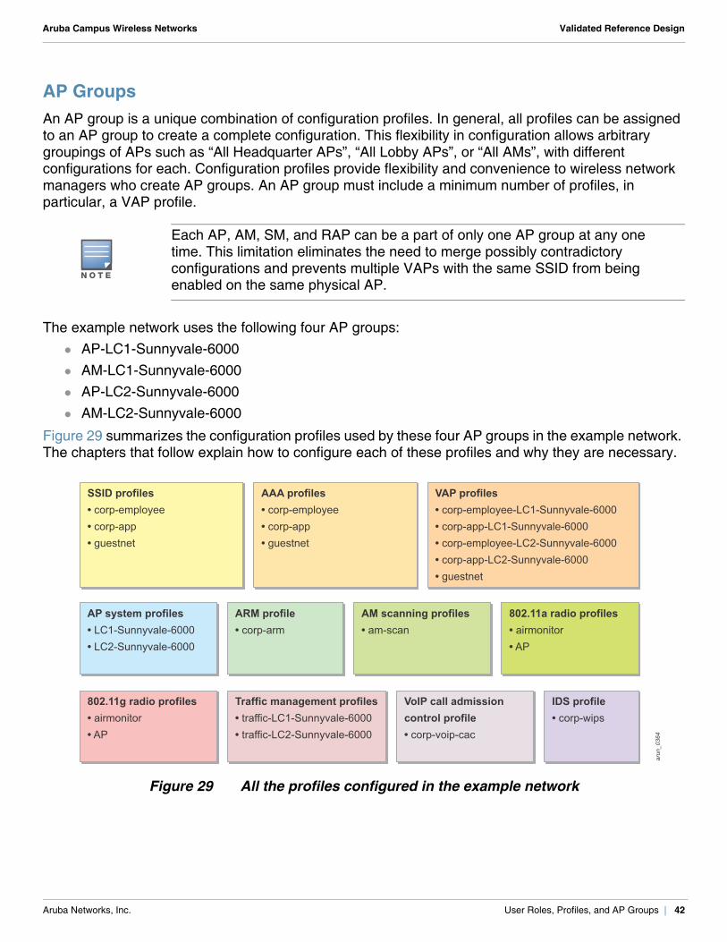
AP GroupsAn AP group is a unique combination of configuration profiles. In general, all profiles can be assigned to an AP group to create a complete configuration. This flexibility in configuration allows arbitrary groupings of APs such as “All Headquarter APs”, “All Lobby APs”, or “All AMs”, with different configurations for each. Configuration profiles provide flexibility and convenience to wireless network managers who create AP groups. An AP group must include a minimum number of profiles, in particular, a VAP profile.
The example network uses the following four AP groups: AP-LC1-Sunnyvale-6000 AM-LC1-Sunnyvale-6000 AP-LC2-Sunnyvale-6000 AM-LC2-Sunnyvale-6000
Figure 29 summarizes the configuration profiles used by these four AP groups in the example network. The chapters that follow explain how to configure each of these profiles and why they are necessary.
Figure 29 All the profiles configured in the example network
N O T E
Each AP, AM, SM, and RAP can be a part of only one AP group at any one time. This limitation eliminates the need to merge possibly contradictory configurations and prevents multiple VAPs with the same SSID from being enabled on the same physical AP.
arun_0364
SSID profiles• corp-employee• corp-app• guestnet
AP system profiles• LC1-Sunnyvale-6000• LC2-Sunnyvale-6000
AM scanning profiles• am-scan
802.11a radio profiles• airmonitor• AP
802.11g radio profiles• airmonitor• AP
ARM profile• corp-arm
IDS profile• corp-wips
VoIP call admissioncontrol profile• corp-voip-cac
AAA profiles• corp-employee• corp-app• guestnet
VAP profiles• corp-employee-LC1-Sunnyvale-6000• corp-app-LC1-Sunnyvale-6000• corp-employee-LC2-Sunnyvale-6000• corp-app-LC2-Sunnyvale-6000• guestnet
Traffic management profiles• traffic-LC1-Sunnyvale-6000• traffic-LC2-Sunnyvale-6000
Aruba Networks, Inc. User Roles, Profiles, and AP Groups | 42
Aruba Campus Wireless Networks Validated Reference Design
Chapter 7: AP Groups for Client Access
When you create an AP group for client access you create a functional WLAN for client access. To create an AP group for client access, you need to configure these:
firewall policies and user roles (required) SSID profile (required) server groups, AAA profile (required) VAP profile (required) Adaptive Radio Management (ARM) profile (optional, but recommended) 802.11a radio profile (required) 802.11g radio profile (required) AP system profile (required) 802.11a traffic management profile (optional, but recommended) 802.11g traffic management profile (optional, but recommended) VoIP call admission control profile (optional, but recommended) IDS profile (optional, but recommended)
The following chapters explain the configuration of the AP-LC1-Sunnyvale-6000 and AP-LC2-Sunnyvale-6000 AP groups for client access. The AP-LC1-Sunnyvale-6000 AP group is used for all APs that must be managed by the LC1-Sunnyvale-6000 local controller. The AP-LC2-Sunnyvale-6000 AP group is used for all APs that must be managed by the LC2-Sunnyvale-6000 local controller.
The APs that belong to one of these two AP groups perform these actions: Broadcast employee, application, and guest SSIDs in both 2.4 GHz and 5 GHz bands. Participate in ARM and band steering. Terminate on VRRP-7 VIP if they are in the AP-LC1-Sunnyvale-6000 AP group or on VRRP-8
VIP if they belong to the AP-LC2-Sunnyvale-6000 AP group. Participate in prioritizing traffic based on SSID and WMM category. Participate in VoIP call admission control. Participate in wireless intrusion prevention.
Aruba Networks, Inc. AP Groups for Client Access | 43
Aruba Campus Wireless Networks Validated Reference Design
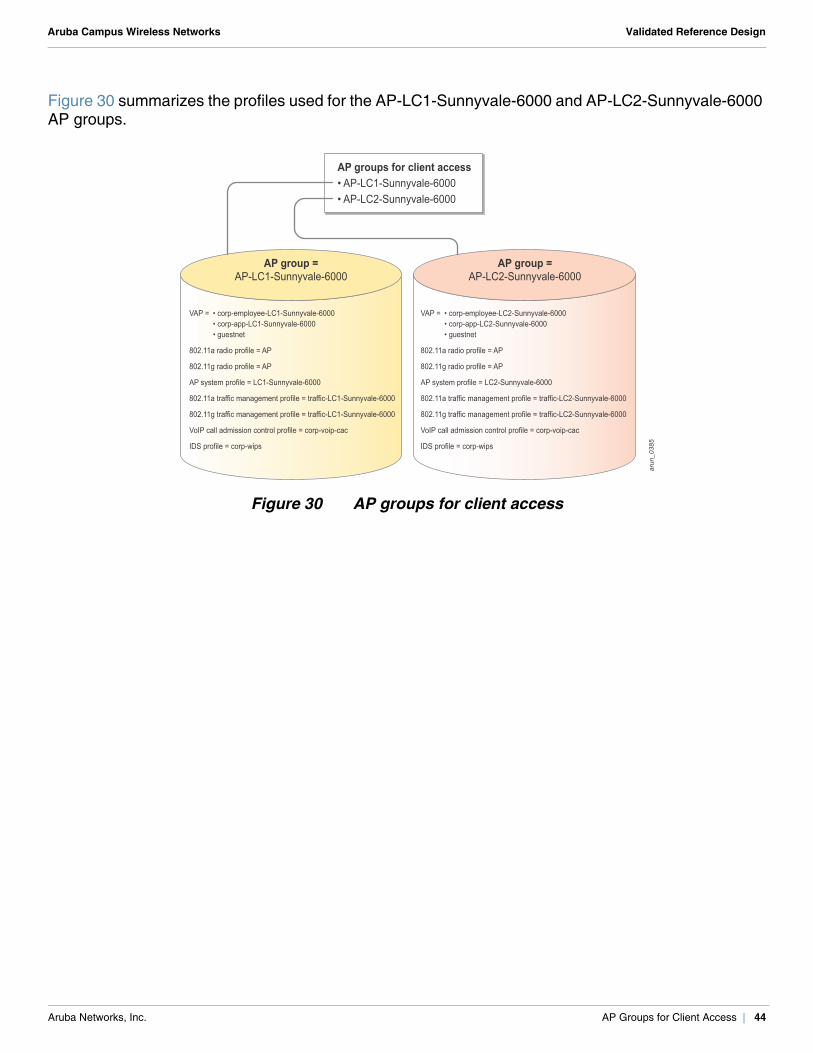
Figure 30 summarizes the profiles used for the AP-LC1-Sunnyvale-6000 and AP-LC2-Sunnyvale-6000 AP groups.
Figure 30 AP groups for client access
VAP =
802.11a radio profile = AP
802.11g radio profile = AP
AP system profile = LC1-Sunnyvale-6000
802.11a traffic management profile = traffic-LC1-Sunnyvale-6000
802.11g traffic management profile = traffic-LC1-Sunnyvale-6000
VoIP call admission control profile = corp-voip-cac
IDS profile = corp-wips
• corp-employee-LC1-Sunnyvale-6000• corp-app-LC1-Sunnyvale-6000• guestnet
VAP =
802.11a radio profile = AP
802.11g radio profile = AP
AP system profile = LC2-Sunnyvale-6000
802.11a traffic management profile = traffic-LC2-Sunnyvale-6000
802.11g traffic management profile = traffic-LC2-Sunnyvale-6000
VoIP call admission control profile = corp-voip-cac
IDS profile = corp-wips
• corp-employee-LC2-Sunnyvale-6000• corp-app-LC2-Sunnyvale-6000• guestnet
arun_0385
AP groups for client access• AP-LC1-Sunnyvale-6000• AP-LC2-Sunnyvale-6000
AP group =AP-LC1-Sunnyvale-6000
AP group =AP-LC2-Sunnyvale-6000
Aruba Networks, Inc. AP Groups for Client Access | 44
Aruba Campus Wireless Networks Validated Reference Design
Chapter 8: Configuring the Employee Role
Company employees can be granted a role based on their specific job function, department, domain, or they can be given a universal employee role. In certain organizations, users typically are placed in a single user role that has access to all internal and external resources.
The employee role used in the example network grants unrestricted access to the internal and external resources, but denies personal DHCP servers. The employee role is the default role assigned to clients after successful 802.1X authentication to the employee SSID. This role gives voice traffic priority over standard data traffic. All company employees and devices capable of 802.1X/EAP use the employee SSID.
Before you configure the employee role, first you must create the policies associated with it. The employee role in the example network uses the following policies:
common sip-session-allow ocs-lync allowall (predefined)
Configuring the Common PolicyIn most campus deployments, all users should be denied certain services, no matter what their roles. This common policy is used by the employee role to do the following things:
Deny users from activating their personal DHCP servers on the network. Allow ping across the network. Allow DNS queries only to certain predefined DNS servers.
Remember, the order of rules within a policy determines the behavior of the policy.
Aruba Networks, Inc. Configuring the Employee Role | 45
Aruba Campus Wireless Networks Validated Reference Design
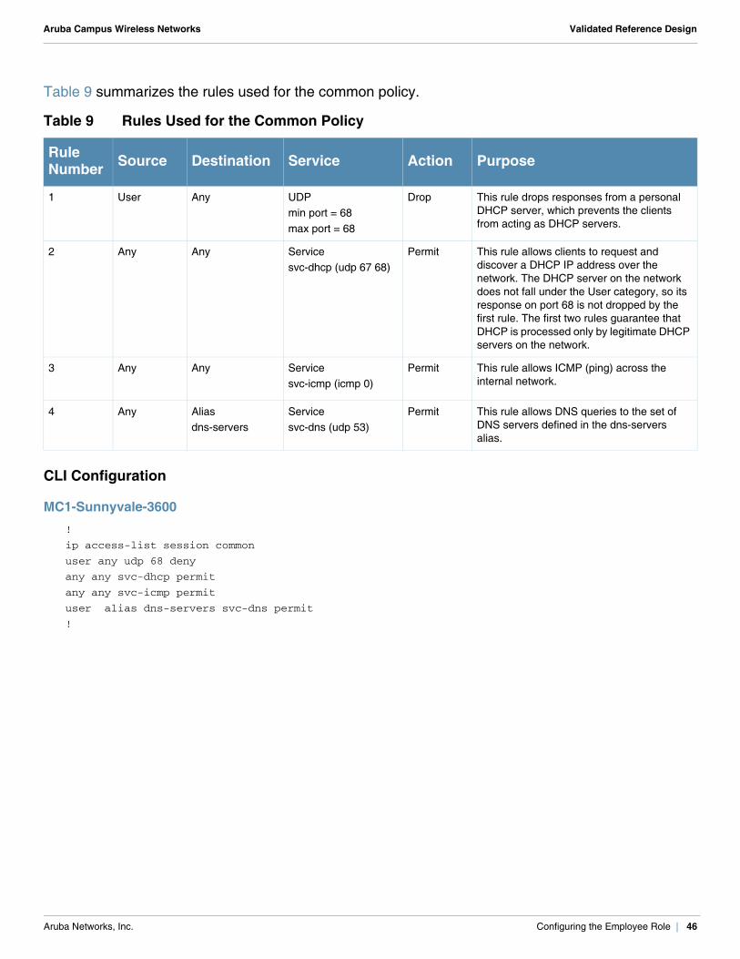
Table 9 summarizes the rules used for the common policy.
CLI Configuration
MC1-Sunnyvale-3600!
ip access-list session common
user any udp 68 deny
any any svc-dhcp permit
any any svc-icmp permit
user alias dns-servers svc-dns permit
!
Table 9 Rules Used for the Common Policy
Rule Number Source Destination Service Action Purpose
1 User Any UDP min port = 68max port = 68
Drop This rule drops responses from a personal DHCP server, which prevents the clients from acting as DHCP servers.
2 Any Any Servicesvc-dhcp (udp 67 68)
Permit This rule allows clients to request and discover a DHCP IP address over the network. The DHCP server on the network does not fall under the User category, so its response on port 68 is not dropped by the first rule. The first two rules guarantee that DHCP is processed only by legitimate DHCP servers on the network.
3 Any Any Service svc-icmp (icmp 0)
Permit This rule allows ICMP (ping) across the internal network.
4 Any Aliasdns-servers
Service svc-dns (udp 53)
Permit This rule allows DNS queries to the set of DNS servers defined in the dns-servers alias.
Aruba Networks, Inc. Configuring the Employee Role | 46
Aruba Campus Wireless Networks Validated Reference Design
WebUI Screenshot
MC1-Sunnyvale-3600
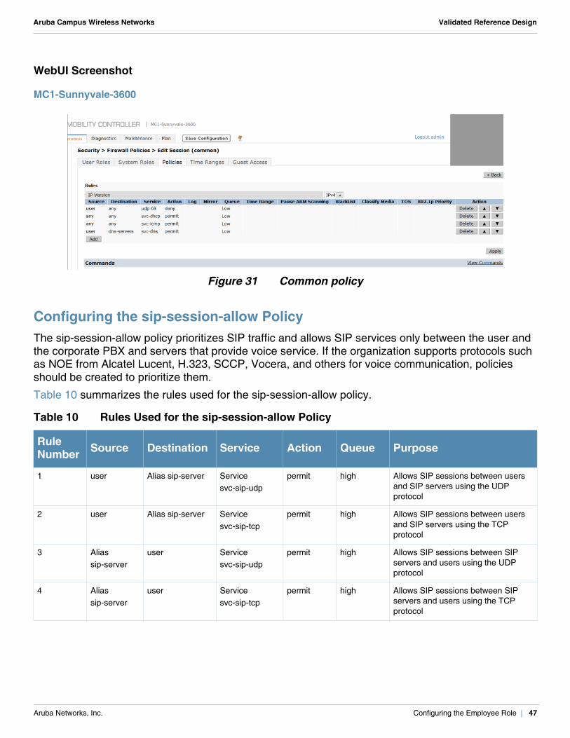
Figure 31 Common policy
Configuring the sip-session-allow PolicyThe sip-session-allow policy prioritizes SIP traffic and allows SIP services only between the user and the corporate PBX and servers that provide voice service. If the organization supports protocols such as NOE from Alcatel Lucent, H.323, SCCP, Vocera, and others for voice communication, policies should be created to prioritize them.
Table 10 summarizes the rules used for the sip-session-allow policy.
Table 10 Rules Used for the sip-session-allow Policy
Rule Number Source Destination Service Action Queue Purpose
1 user Alias sip-server Servicesvc-sip-udp
permit high Allows SIP sessions between users and SIP servers using the UDP protocol
2 user Alias sip-server Servicesvc-sip-tcp
permit high Allows SIP sessions between users and SIP servers using the TCP protocol
3 Alias sip-server
user Servicesvc-sip-udp
permit high Allows SIP sessions between SIP servers and users using the UDP protocol
4 Alias sip-server
user Servicesvc-sip-tcp
permit high Allows SIP sessions between SIP servers and users using the TCP protocol
Aruba Networks, Inc. Configuring the Employee Role | 47
Aruba Campus Wireless Networks Validated Reference Design
CLI Configuration
MC1-Sunnyvale-3600!
ip access-list session sip-session-allow
user alias sip-server svc-sip-udp permit queue high
user alias sip-server svc-sip-tcp permit queue high
alias sip-server user svc-sip-udp permit queue high
alias sip-server user svc-sip-tcp permit queue high
!
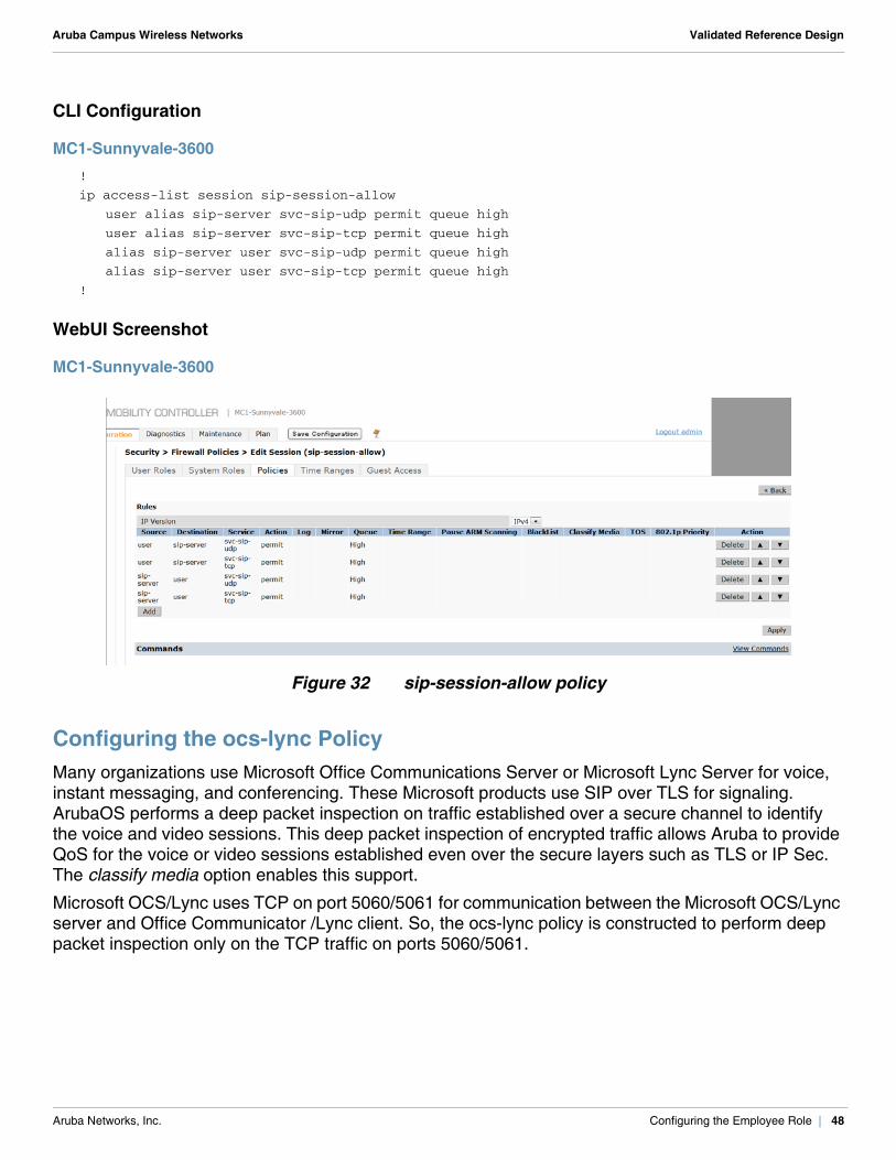
WebUI Screenshot
MC1-Sunnyvale-3600
Figure 32 sip-session-allow policy
Configuring the ocs-lync PolicyMany organizations use Microsoft Office Communications Server or Microsoft Lync Server for voice, instant messaging, and conferencing. These Microsoft products use SIP over TLS for signaling. ArubaOS performs a deep packet inspection on traffic established over a secure channel to identify the voice and video sessions. This deep packet inspection of encrypted traffic allows Aruba to provide QoS for the voice or video sessions established even over the secure layers such as TLS or IP Sec. The classify media option enables this support.
Microsoft OCS/Lync uses TCP on port 5060/5061 for communication between the Microsoft OCS/Lync server and Office Communicator /Lync client. So, the ocs-lync policy is constructed to perform deep packet inspection only on the TCP traffic on ports 5060/5061.
Aruba Networks, Inc. Configuring the Employee Role | 48
Aruba Campus Wireless Networks Validated Reference Design
Table 11 summarizes the rules used for the ocs-lync policy.
CLI Configuration
MC1-Sunnyvale-3600!
ip access-list session ocs-lync
user alias ocs-lync svc-sips permit classify-media queue high
user alias ocs-lync svc-sip-tcp permit classify-media queue high
alias ocs-lync any svc-sips permit classify-media queue high
alias ocs-lync any svc-sip-tcp permit classify-media queue high
!
Table 11 Rules Used for the ocs-lync Policy
Rule Number Source Destination Service Action Queue Classify
Media Purpose
1 User Aliasocs-lync
Service svc-sips (tcp 5061)
permit high Enabled This rule performs deep packet inspection and prioritization of encrypted voice, and video sessions of OCS/Lync.2 User Alias
ocs-lyncService svc-sip-tcp (tcp 5060)
Permit high Enabled
3 Aliasocs-lync
any Service svc-sips (tcp 5061)
Permit high Enabled
4 Aliasocs-lync
any Service svc-sip-tcp (tcp 5060)
permit high Enabled
!CAUTION
Selecting any for the service field and setting the classify media flag, has an impact on performance because it turns on deep packet inspection for all traffic types. Choose this option only for services that require it.
Aruba Networks, Inc. Configuring the Employee Role | 49
Aruba Campus Wireless Networks Validated Reference Design
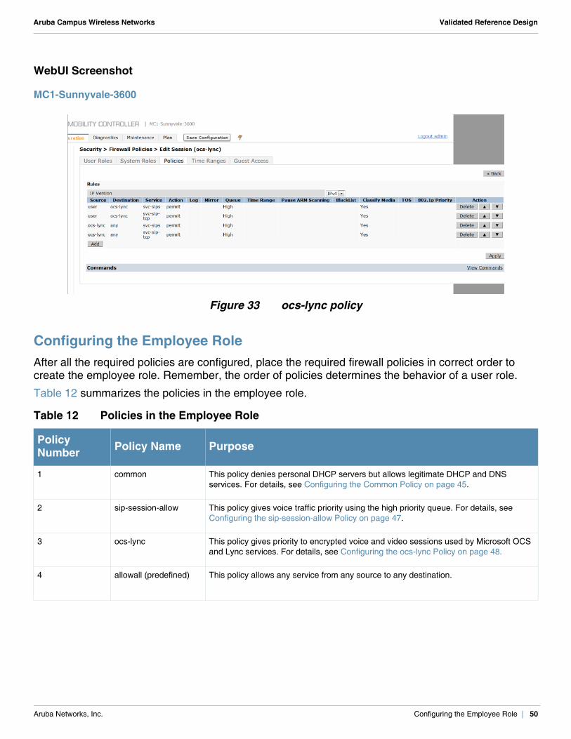
WebUI Screenshot
MC1-Sunnyvale-3600
Figure 33 ocs-lync policy
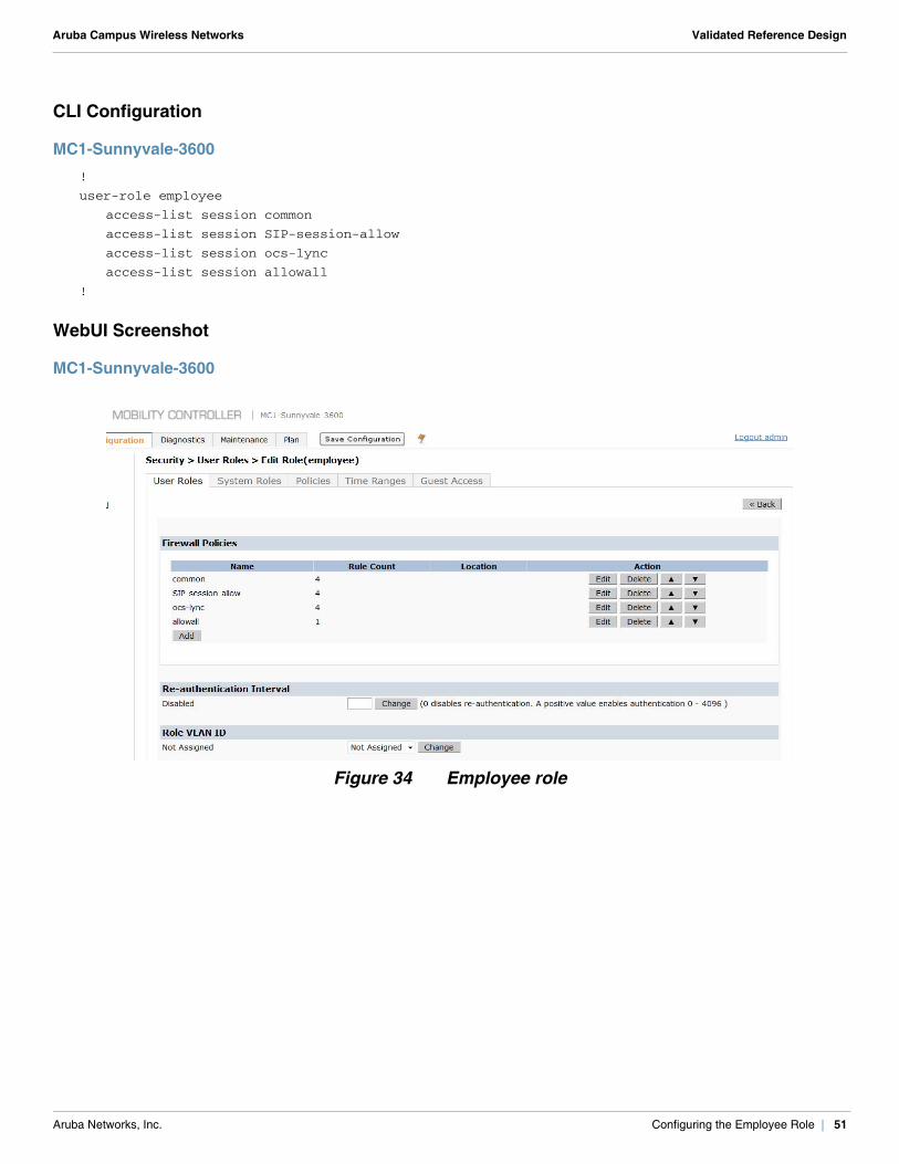
Configuring the Employee RoleAfter all the required policies are configured, place the required firewall policies in correct order to create the employee role. Remember, the order of policies determines the behavior of a user role.
Table 12 summarizes the policies in the employee role.
Table 12 Policies in the Employee Role
Policy Number Policy Name Purpose
1 common This policy denies personal DHCP servers but allows legitimate DHCP and DNS services. For details, see Configuring the Common Policy on page 45.
2 sip-session-allow This policy gives voice traffic priority using the high priority queue. For details, see Configuring the sip-session-allow Policy on page 47.
3 ocs-lync This policy gives priority to encrypted voice and video sessions used by Microsoft OCS and Lync services. For details, see Configuring the ocs-lync Policy on page 48.
4 allowall (predefined) This policy allows any service from any source to any destination.
Aruba Networks, Inc. Configuring the Employee Role | 50
Aruba Campus Wireless Networks Validated Reference Design
CLI Configuration
MC1-Sunnyvale-3600!
user-role employee
access-list session common
access-list session SIP-session-allow
access-list session ocs-lync
access-list session allowall
!
WebUI Screenshot
MC1-Sunnyvale-3600
Figure 34 Employee role
Aruba Networks, Inc. Configuring the Employee Role | 51

Aruba Campus Wireless Networks Validated Reference Design
Aruba Networks, Inc. Configuring the Employee Role | 52
Aruba Campus Wireless Networks Validated Reference Design
Chapter 9: Employee VAP Profiles
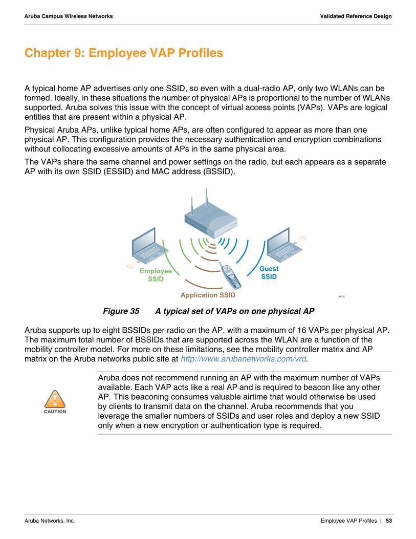
A typical home AP advertises only one SSID, so even with a dual-radio AP, only two WLANs can be formed. Ideally, in these situations the number of physical APs is proportional to the number of WLANs supported. Aruba solves this issue with the concept of virtual access points (VAPs). VAPs are logical entities that are present within a physical AP.
Physical Aruba APs, unlike typical home APs, are often configured to appear as more than one physical AP. This configuration provides the necessary authentication and encryption combinations without collocating excessive amounts of APs in the same physical area.
The VAPs share the same channel and power settings on the radio, but each appears as a separate AP with its own SSID (ESSID) and MAC address (BSSID).
Figure 35 A typical set of VAPs on one physical AP
Aruba supports up to eight BSSIDs per radio on the AP, with a maximum of 16 VAPs per physical AP. The maximum total number of BSSIDs that are supported across the WLAN are a function of the mobility controller model. For more on these limitations, see the mobility controller matrix and AP matrix on the Aruba networks public site at http://www.arubanetworks.com/vrd.
!CAUTION
Aruba does not recommend running an AP with the maximum number of VAPs available. Each VAP acts like a real AP and is required to beacon like any other AP. This beaconing consumes valuable airtime that would otherwise be used by clients to transmit data on the channel. Aruba recommends that you leverage the smaller numbers of SSIDs and user roles and deploy a new SSID only when a new encryption or authentication type is required.
arun
EmployeeSSID
Application SSID
GuestSSID
Aruba Networks, Inc. Employee VAP Profiles | 53

Aruba Campus Wireless Networks Validated Reference Design
A VAP profile is a container that holds an AAA profile, SSID profile, 802.11k profile, and WMM traffic management profile. At minimum, each VAP profile must have an AAA and SSID profile. The VAP profile also has other configurable features, such as band steering, dynamic multicast optimization, fast roaming, and DoS prevention.
Table 13 summarizes the VAP profiles used in the example network.
Configuring the SSID ProfilesService Set Identifier (SSID) is the network or WLAN that any client sees. A SSID profile defines parameters, such as name of the network, authentication type for the network, basic rates, transmit rates, SSID cloaking, and certain WMM settings for the network.
Aruba offers different flavors of the Advanced Encryption Standard (AES), Temporal Key Integrity Protocol (TKIP), and wired equivalent privacy (WEP) encryption. AES is the most secure and recommended encryption method. Most modern devices are AES capable and AES should be the default encryption method. Use TKIP only when devices that are not AES capable are present. In these situations, use a separate SSID for devices that are only capable of TKIP. It is important to understand that several vulnerabilities have been reported with TKIP. Avoid using WEP, because it can be cracked in less than 5 minutes with generally available tools. Aruba also supports a host of authentication methods such as 802.1X, captive portal, PSK, and WEP.
N O T E
The BSSID assigned to each of the 16 possible SSIDs on a physical AP are generated from the MAC address of the physical AP. A total of 16 BSSIDs are generated by the algorithm. The BSSID assigned to each SSID is random. Whenever an AP reboots the BSSID to SSID mapping may change. In certain situations a SSID may be temporarily disabled for maintenance, when this SSID is enabled again, the BSSID assigned to it might not be the same as before.
Table 13 VAP Profiles Used in the Example Network
VAP Profile AP Group VLAN/ VLAN Pool
Corp-Employee-LC1-Sunnyvale-6000 AP-LC1-Sunnyvale-6000 pool-7
Corp-App-LC1-Sunnyvale-6000 AP-LC1-Sunnyvale-6000 pool-7
Corp-Employee-LC2-Sunnyvale-6000 AP-LC2-Sunnyvale-6000 pool-8
Corp-App-LC2-Sunnyvale-6000 AP-LC2-Sunnyvale-6000 pool-8
guestnet AP-LC1-Sunnyvale-6000, AP-LC2-Sunnyvale-6000
900
Aruba Networks, Inc. Employee VAP Profiles | 54
Aruba Campus Wireless Networks Validated Reference Design
Configuring the Employee SSID Profile
By default, all employees and corporate devices should connect to the employee SSID. The use of 802.1X with a backend RADIUS server and AES encryption makes this the most secure network. For more information about authentication types, encryption methods, and role derivation on the Aruba Mobility Controller for Wi-Fi Protected Access® 2 (WPA2™), see the Aruba 802.11n Networks Validated Reference Design.
Configuring Wi-Fi Multimedia
Wi-Fi Multimedia™ (WMM®) is a Wi-Fi Alliance® certification program that is based on the IEEE 802.11e amendment. WMM ensures QoS for latency-sensitive traffic in the air. WMM divides the traffic into four queues or access categories:
voice video best effort background
The traffic is prioritized based on the queue it belongs to. The order of priority is voice > video > best effort > background. Like WMM for QoS in air, QoS on the wired side of the network is dictated by the DiffServ Code Point (DSCP) and 802.1p tagging. To ensure end-to-end QoS on the network, consider these requirements:
The DSCP tags should translate to appropriate WMM access categories and vice-versa. The Aruba infrastructure ensures this translation between WMM and DSCP/802.1P markings when the traffic moves across wired and wireless mediums.
All devices in the network should be capable of and configured for QoS support. The LAN that is between the AP and the mobility controller must recognize and prioritize DCSP-marked traffic through the network. Similarly, the core must respect the DSCP marks from the mobility controller to the multimedia servers.
For more information about the mapping between WMM access categories, DSCP tags and other QoS functionalities, see the Aruba 802.11n Networks Validated Reference Design. In the example network, the WMM parameter is enabled on the employee SSID to prioritize latency-sensitive traffic, such as voice and video, over the standard data traffic. The DSCP-to-WMM mapping is a configurable parameter that is available within the SSID profile. In the example network, the DSCP-to-WMM mapping values are set to the defaults. The Aruba default DSCP-to-WMM mapping values match the default DSCP settings of most vendors. Alter the Aruba defaults only if they vary from your existing DSCP settings.
Aruba Networks, Inc. Employee VAP Profiles | 55
Aruba Campus Wireless Networks Validated Reference Design
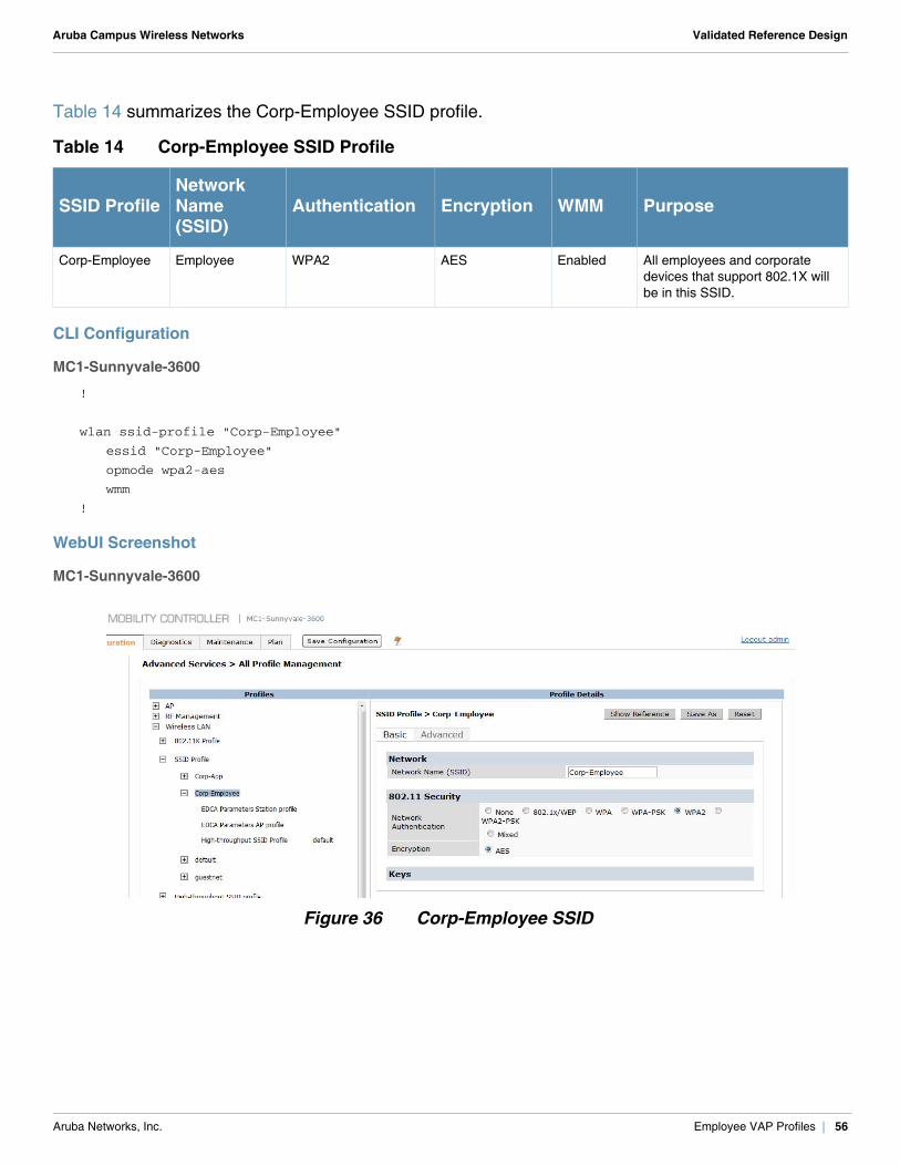
Table 14 summarizes the Corp-Employee SSID profile.
CLI Configuration
MC1-Sunnyvale-3600
!
wlan ssid-profile "Corp-Employee"
essid "Corp-Employee"
opmode wpa2-aes
wmm
!
WebUI Screenshot
MC1-Sunnyvale-3600
Figure 36 Corp-Employee SSID
Table 14 Corp-Employee SSID Profile
SSID ProfileNetworkName (SSID)
Authentication Encryption WMM Purpose
Corp-Employee Employee WPA2 AES Enabled All employees and corporate devices that support 802.1X will be in this SSID.
Aruba Networks, Inc. Employee VAP Profiles | 56
Aruba Campus Wireless Networks Validated Reference Design
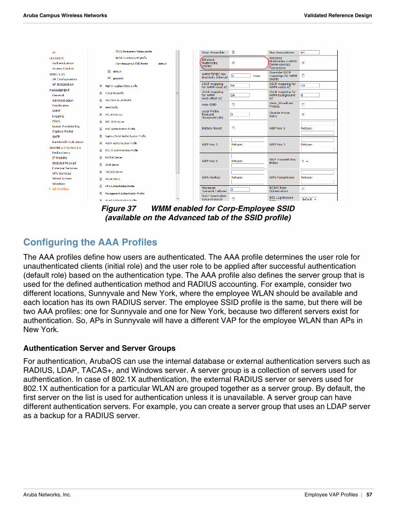
Figure 37 WMM enabled for Corp-Employee SSID (available on the Advanced tab of the SSID profile)
Configuring the AAA ProfilesThe AAA profiles define how users are authenticated. The AAA profile determines the user role for unauthenticated clients (initial role) and the user role to be applied after successful authentication (default role) based on the authentication type. The AAA profile also defines the server group that is used for the defined authentication method and RADIUS accounting. For example, consider two different locations, Sunnyvale and New York, where the employee WLAN should be available and each location has its own RADIUS server. The employee SSID profile is the same, but there will be two AAA profiles: one for Sunnyvale and one for New York, because two different servers exist for authentication. So, APs in Sunnyvale will have a different VAP for the employee WLAN than APs in New York.
Authentication Server and Server Groups
For authentication, ArubaOS can use the internal database or external authentication servers such as RADIUS, LDAP, TACAS+, and Windows server. A server group is a collection of servers used for authentication. In case of 802.1X authentication, the external RADIUS server or servers used for 802.1X authentication for a particular WLAN are grouped together as a server group. By default, the first server on the list is used for authentication unless it is unavailable. A server group can have different authentication servers. For example, you can create a server group that uses an LDAP server as a backup for a RADIUS server.
Aruba Networks, Inc. Employee VAP Profiles | 57
Aruba Campus Wireless Networks Validated Reference Design
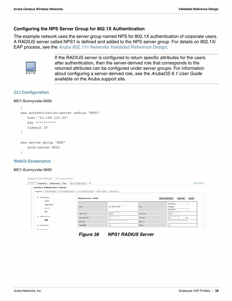
Configuring the NPS Server Group for 802.1X Authentication
The example network uses the server group named NPS for 802.1X authentication of corporate users. A RADIUS server called NPS1 is defined and added to the NPS server group. For details on 802.1X/EAP process, see the Aruba 802.11n Networks Validated Reference Design.
CLI Configuration
MC1-Sunnyvale-3600
!
aaa authentication-server radius "NPS1"
host "10.169.130.20"
key **********
timeout 30
!
aaa server-group "NPS"
auth-server NPS1
!
WebUI Screenshot
MC1-Sunnyvale-3600
Figure 38 NPS1 RADIUS Server
N O T E
If the RADIUS server is configured to return specific attributes for the users after authentication, then the server-derived role that corresponds to the returned attributes can be configured under server groups. For information about configuring a server-derived role, see the ArubaOS 6.1 User Guide available on the Aruba support site.
Aruba Networks, Inc. Employee VAP Profiles | 58
Aruba Campus Wireless Networks Validated Reference Design
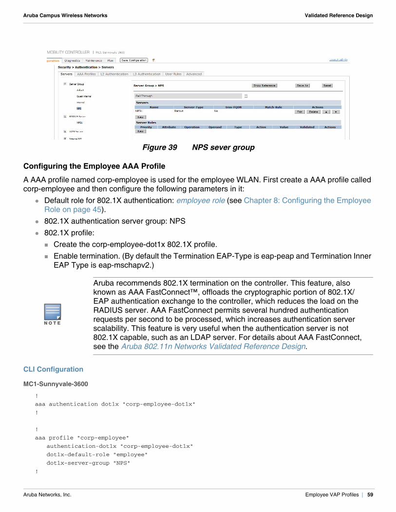
Figure 39 NPS sever group
Configuring the Employee AAA Profile
A AAA profile named corp-employee is used for the employee WLAN. First create a AAA profile called corp-employee and then configure the following parameters in it:
Default role for 802.1X authentication: employee role (see Chapter 8: Configuring the Employee Role on page 45).
802.1X authentication server group: NPS 802.1X profile:
Create the corp-employee-dot1x 802.1X profile. Enable termination. (By default the Termination EAP-Type is eap-peap and Termination Inner
EAP Type is eap-mschapv2.)
CLI Configuration
MC1-Sunnyvale-3600
!
aaa authentication dot1x "corp-employee-dot1x"
!
!
aaa profile "corp-employee"
authentication-dot1x "corp-employee-dot1x"
dot1x-default-role "employee"
dot1x-server-group "NPS"
!
N O T E
Aruba recommends 802.1X termination on the controller. This feature, also known as AAA FastConnect™, offloads the cryptographic portion of 802.1X/EAP authentication exchange to the controller, which reduces the load on the RADIUS server. AAA FastConnect permits several hundred authentication requests per second to be processed, which increases authentication server scalability. This feature is very useful when the authentication server is not 802.1X capable, such as an LDAP server. For details about AAA FastConnect, see the Aruba 802.11n Networks Validated Reference Design.
Aruba Networks, Inc. Employee VAP Profiles | 59
Aruba Campus Wireless Networks Validated Reference Design
WebUI Screenshot
MC1-Sunnyvale-3600
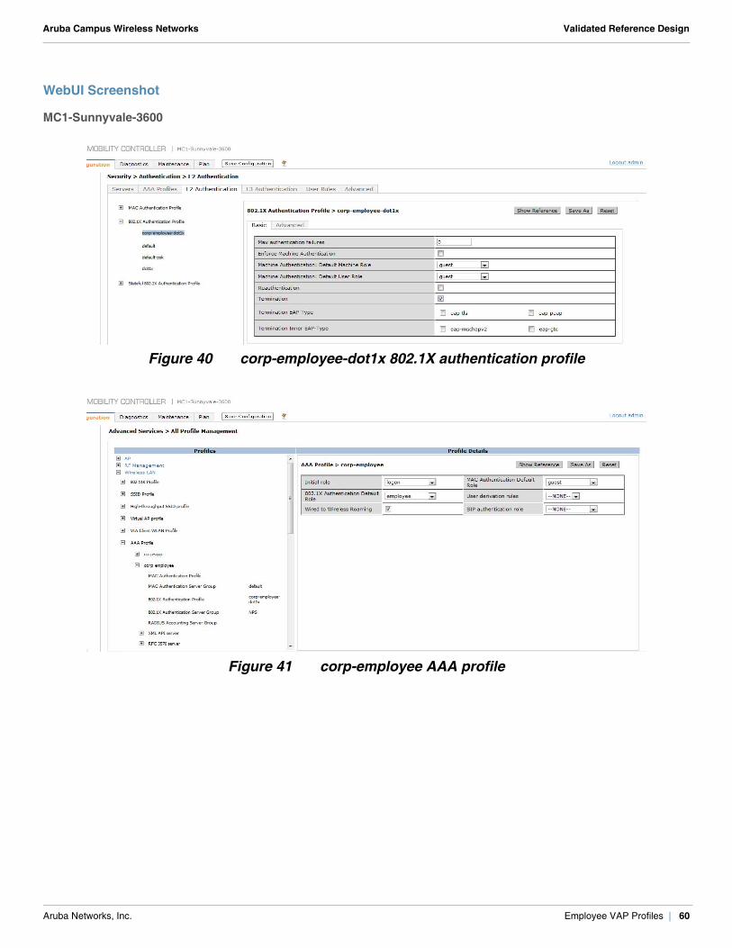
Figure 40 corp-employee-dot1x 802.1X authentication profile
Figure 41 corp-employee AAA profile
Aruba Networks, Inc. Employee VAP Profiles | 60
Aruba Campus Wireless Networks Validated Reference Design
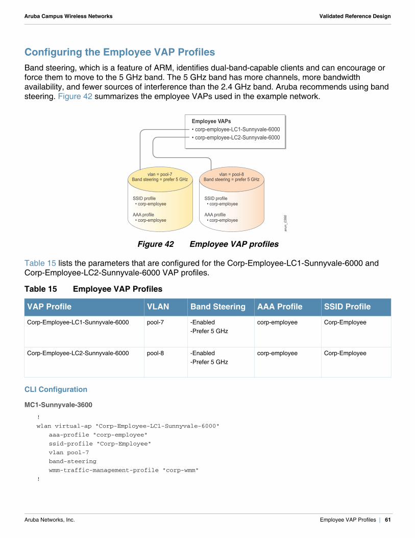
Configuring the Employee VAP ProfilesBand steering, which is a feature of ARM, identifies dual-band-capable clients and can encourage or force them to move to the 5 GHz band. The 5 GHz band has more channels, more bandwidth availability, and fewer sources of interference than the 2.4 GHz band. Aruba recommends using band steering. Figure 42 summarizes the employee VAPs used in the example network.
Figure 42 Employee VAP profiles
Table 15 lists the parameters that are configured for the Corp-Employee-LC1-Sunnyvale-6000 and Corp-Employee-LC2-Sunnyvale-6000 VAP profiles.
CLI Configuration
MC1-Sunnyvale-3600
!
wlan virtual-ap "Corp-Employee-LC1-Sunnyvale-6000"
aaa-profile "corp-employee"
ssid-profile "Corp-Employee"
vlan pool-7
band-steering
wmm-traffic-management-profile "corp-wmm"
!
Table 15 Employee VAP Profiles
VAP Profile VLAN Band Steering AAA Profile SSID Profile
Corp-Employee-LC1-Sunnyvale-6000 pool-7 -Enabled-Prefer 5 GHz
corp-employee Corp-Employee
Corp-Employee-LC2-Sunnyvale-6000 pool-8 -Enabled-Prefer 5 GHz
corp-employee Corp-Employee
SSID profile • corp-employee
AAA profile • corp-employee
SSID profile • corp-employee
AAA profile • corp-employee
arun_0366
Employee VAPs• corp-employee-LC1-Sunnyvale-6000• corp-employee-LC2-Sunnyvale-6000
vlan = pool-7Band steering = prefer 5 GHz
vlan = pool-8Band steering = prefer 5 GHz
Aruba Networks, Inc. Employee VAP Profiles | 61
Aruba Campus Wireless Networks Validated Reference Design
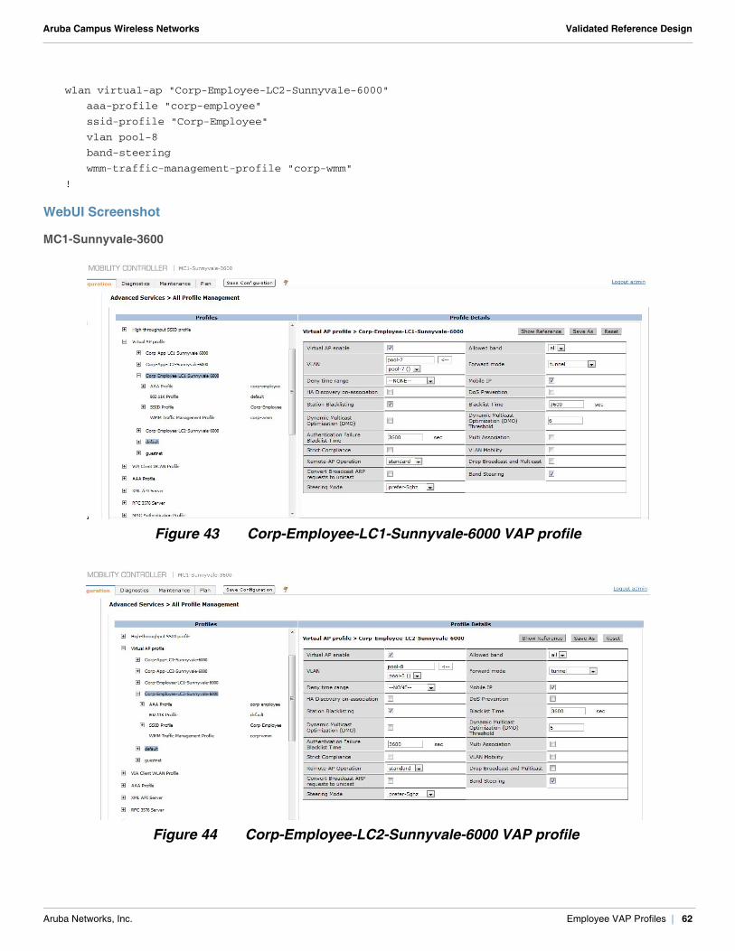
wlan virtual-ap "Corp-Employee-LC2-Sunnyvale-6000"
aaa-profile "corp-employee"
ssid-profile "Corp-Employee"
vlan pool-8
band-steering
wmm-traffic-management-profile "corp-wmm"
!
WebUI Screenshot
MC1-Sunnyvale-3600
Figure 43 Corp-Employee-LC1-Sunnyvale-6000 VAP profile
Figure 44 Corp-Employee-LC2-Sunnyvale-6000 VAP profile
Aruba Networks, Inc. Employee VAP Profiles | 62
Aruba Campus Wireless Networks Validated Reference Design
Chapter 10: Configuring the Application Role and VAP Profiles
Certain devices, such as legacy handheld scanners and IP video cameras, are not capable of 802.1X/EAP and use PSK for authentication. In cases where PSK has be to supported to accommodate the devices that do not support 802.1X, you must create a separate user role for those applications and devices. Unlike the employee role, this user role should be restricted only to the services and servers required by such devices.
The example network has some SIP phones that are not capable of 802.1X and use the application SSID. These phones use the SIP protocol and need TFTP to download configurations. These phones in the example network need only SIP, DHCP, TFTP, DNS, and ICMP services to operate. Different devices use different protocols for operation. The services that the devices require depend on the vendor. Contact your device vendor to determine the services that are needed for your device operation.
The example network assigns the application user role to the devices that associate to the application SSID. The application role allows access only to the SIP, DHCP, TFTP, DNS, and ICMP services. The application role ensures that the devices that associate to the application SSID access only the required services and servers.
Before you configure the application role, first create the policies that are associated with it. The application role in the example network uses the following policies:
sip-session-allow (For details, see Configuring the sip-session-allow Policy on page 47.) dhcp-acl (predefined) tftp-session-allow dns-acl (predefined) icmp-acl (predefined)
Aruba Networks, Inc. Configuring the Application Role and VAP Profiles | 63
Aruba Campus Wireless Networks Validated Reference Design
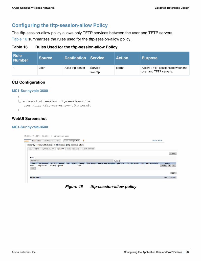
Configuring the tftp-session-allow PolicyThe tftp-session-allow policy allows only TFTP services between the user and TFTP servers.
Table 16 summarizes the rules used for the tftp-session-allow policy.
CLI Configuration
MC1-Sunnyvale-3600!
ip access-list session tftp-session-allow
user alias tftp-server svc-tftp permit
!
WebUI Screenshot
MC1-Sunnyvale-3600
Figure 45 tftp-session-allow policy
Table 16 Rules Used for the tftp-session-allow Policy
Rule Number Source Destination Service Action Purpose
1 user Alias tftp-server Servicesvc-tftp
permit Allows TFTP sessions between the user and TFTP servers.
Aruba Networks, Inc. Configuring the Application Role and VAP Profiles | 64
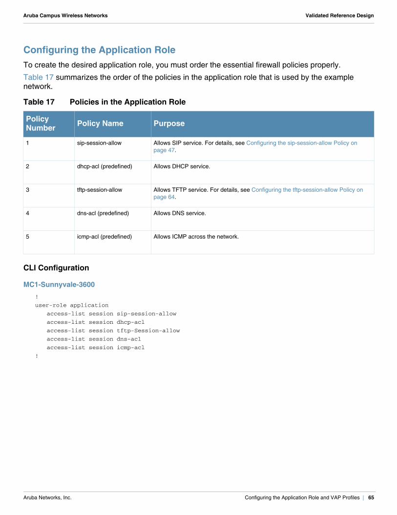
Aruba Campus Wireless Networks Validated Reference Design
Configuring the Application RoleTo create the desired application role, you must order the essential firewall policies properly.
Table 17 summarizes the order of the policies in the application role that is used by the example network.
CLI Configuration
MC1-Sunnyvale-3600!
user-role application
access-list session sip-session-allow
access-list session dhcp-acl
access-list session tftp-Session-allow
access-list session dns-acl
access-list session icmp-acl
!
Table 17 Policies in the Application Role
Policy Number Policy Name Purpose
1 sip-session-allow Allows SIP service. For details, see Configuring the sip-session-allow Policy on page 47.
2 dhcp-acl (predefined) Allows DHCP service.
3 tftp-session-allow Allows TFTP service. For details, see Configuring the tftp-session-allow Policy on page 64.
4 dns-acl (predefined) Allows DNS service.
5 icmp-acl (predefined) Allows ICMP across the network.
Aruba Networks, Inc. Configuring the Application Role and VAP Profiles | 65
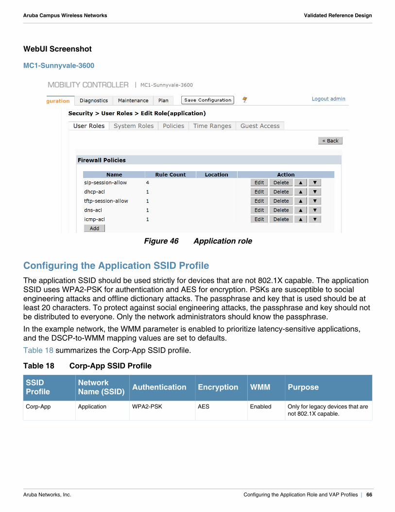
Aruba Campus Wireless Networks Validated Reference Design
WebUI Screenshot
MC1-Sunnyvale-3600
Figure 46 Application role
Configuring the Application SSID ProfileThe application SSID should be used strictly for devices that are not 802.1X capable. The application SSID uses WPA2-PSK for authentication and AES for encryption. PSKs are susceptible to social engineering attacks and offline dictionary attacks. The passphrase and key that is used should be at least 20 characters. To protect against social engineering attacks, the passphrase and key should not be distributed to everyone. Only the network administrators should know the passphrase.
In the example network, the WMM parameter is enabled to prioritize latency-sensitive applications, and the DSCP-to-WMM mapping values are set to defaults.
Table 18 summarizes the Corp-App SSID profile.
Table 18 Corp-App SSID Profile
SSIDProfile
NetworkName (SSID) Authentication Encryption WMM Purpose
Corp-App Application WPA2-PSK AES Enabled Only for legacy devices that are not 802.1X capable.
Aruba Networks, Inc. Configuring the Application Role and VAP Profiles | 66
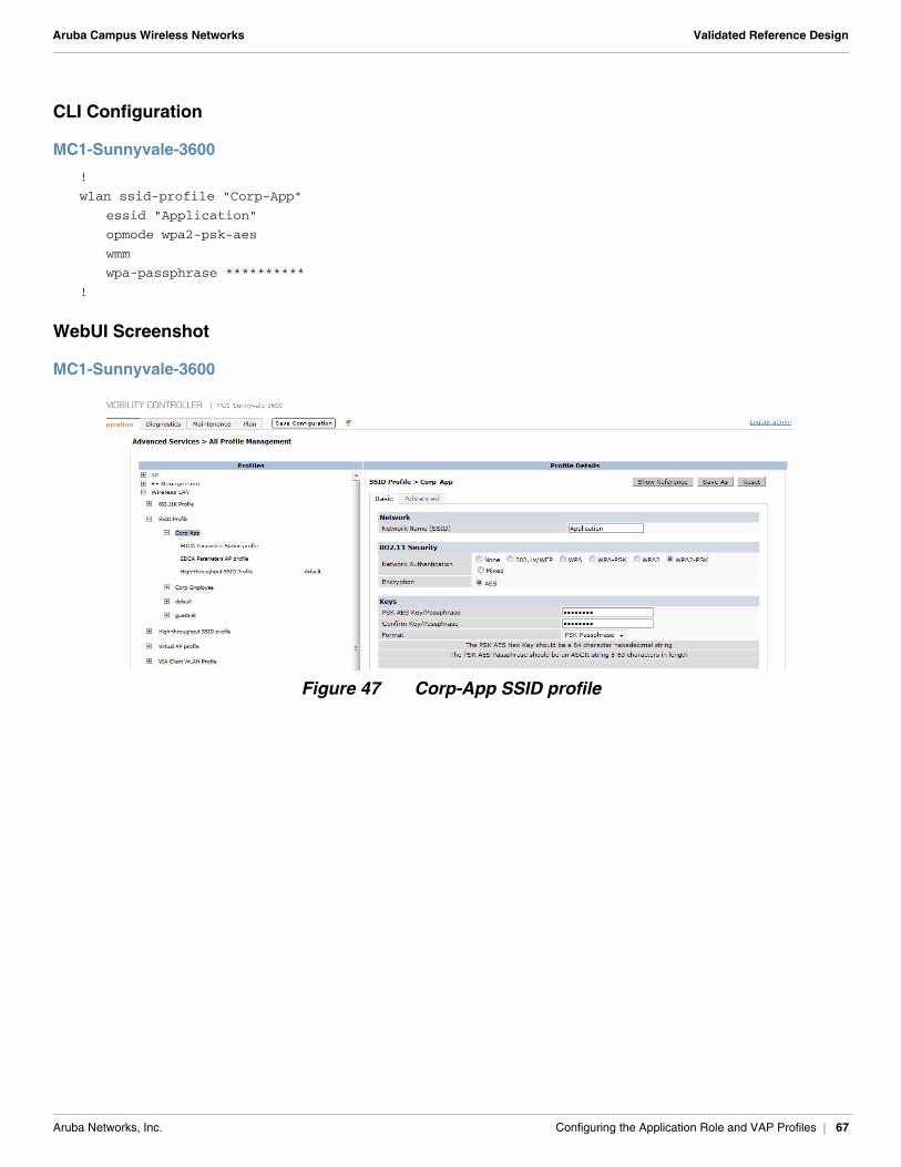
Aruba Campus Wireless Networks Validated Reference Design
CLI Configuration
MC1-Sunnyvale-3600!
wlan ssid-profile "Corp-App"
essid "Application"
opmode wpa2-psk-aes
wmm
wpa-passphrase **********
!
WebUI Screenshot
MC1-Sunnyvale-3600
Figure 47 Corp-App SSID profile
Aruba Networks, Inc. Configuring the Application Role and VAP Profiles | 67
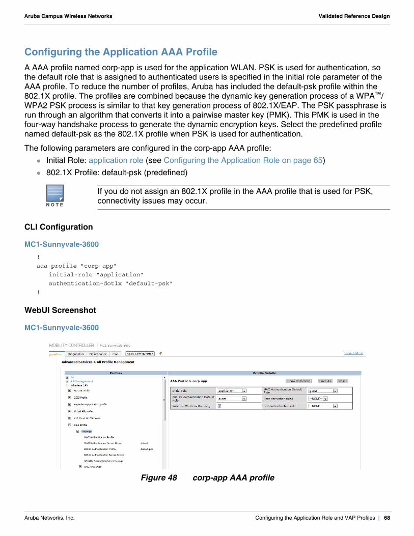
Aruba Campus Wireless Networks Validated Reference Design
Configuring the Application AAA ProfileA AAA profile named corp-app is used for the application WLAN. PSK is used for authentication, so the default role that is assigned to authenticated users is specified in the initial role parameter of the AAA profile. To reduce the number of profiles, Aruba has included the default-psk profile within the 802.1X profile. The profiles are combined because the dynamic key generation process of a WPA™/WPA2 PSK process is similar to that key generation process of 802.1X/EAP. The PSK passphrase is run through an algorithm that converts it into a pairwise master key (PMK). This PMK is used in the four-way handshake process to generate the dynamic encryption keys. Select the predefined profile named default-psk as the 802.1X profile when PSK is used for authentication.
The following parameters are configured in the corp-app AAA profile: Initial Role: application role (see Configuring the Application Role on page 65) 802.1X Profile: default-psk (predefined)
CLI Configuration
MC1-Sunnyvale-3600!
aaa profile "corp-app"
initial-role "application"
authentication-dot1x "default-psk"
!
WebUI Screenshot
MC1-Sunnyvale-3600
Figure 48 corp-app AAA profile
N O T E
If you do not assign an 802.1X profile in the AAA profile that is used for PSK, connectivity issues may occur.
Aruba Networks, Inc. Configuring the Application Role and VAP Profiles | 68
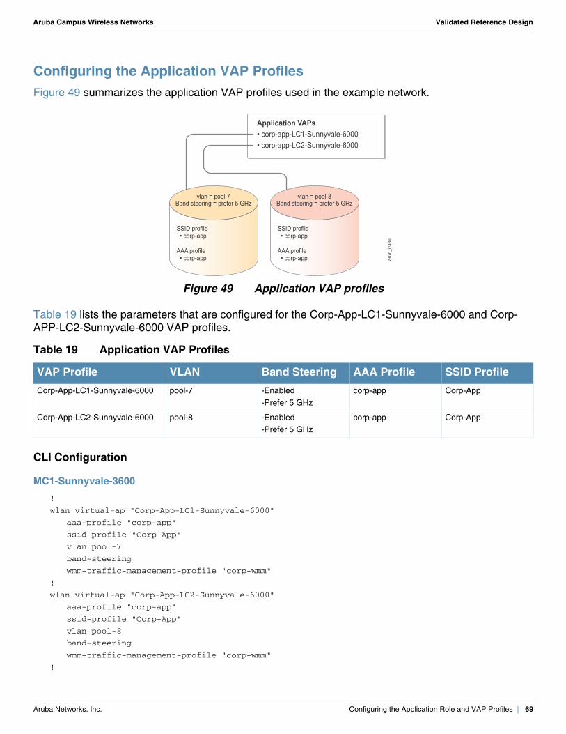
Aruba Campus Wireless Networks Validated Reference Design
Configuring the Application VAP ProfilesFigure 49 summarizes the application VAP profiles used in the example network.
Figure 49 Application VAP profiles
Table 19 lists the parameters that are configured for the Corp-App-LC1-Sunnyvale-6000 and Corp-APP-LC2-Sunnyvale-6000 VAP profiles.
CLI Configuration
MC1-Sunnyvale-3600!
wlan virtual-ap "Corp-App-LC1-Sunnyvale-6000"
aaa-profile "corp-app"
ssid-profile "Corp-App"
vlan pool-7
band-steering
wmm-traffic-management-profile "corp-wmm"
!
wlan virtual-ap "Corp-App-LC2-Sunnyvale-6000"
aaa-profile "corp-app"
ssid-profile "Corp-App"
vlan pool-8
band-steering
wmm-traffic-management-profile "corp-wmm"
!
Table 19 Application VAP Profiles
VAP Profile VLAN Band Steering AAA Profile SSID ProfileCorp-App-LC1-Sunnyvale-6000 pool-7 -Enabled
-Prefer 5 GHzcorp-app Corp-App
Corp-App-LC2-Sunnyvale-6000 pool-8 -Enabled-Prefer 5 GHz
corp-app Corp-App
SSID profile • corp-app
AAA profile • corp-app
SSID profile • corp-app
AAA profile • corp-app ar
un_0386
Application VAPs• corp-app-LC1-Sunnyvale-6000• corp-app-LC2-Sunnyvale-6000
vlan = pool-7Band steering = prefer 5 GHz
vlan = pool-8Band steering = prefer 5 GHz
Aruba Networks, Inc. Configuring the Application Role and VAP Profiles | 69
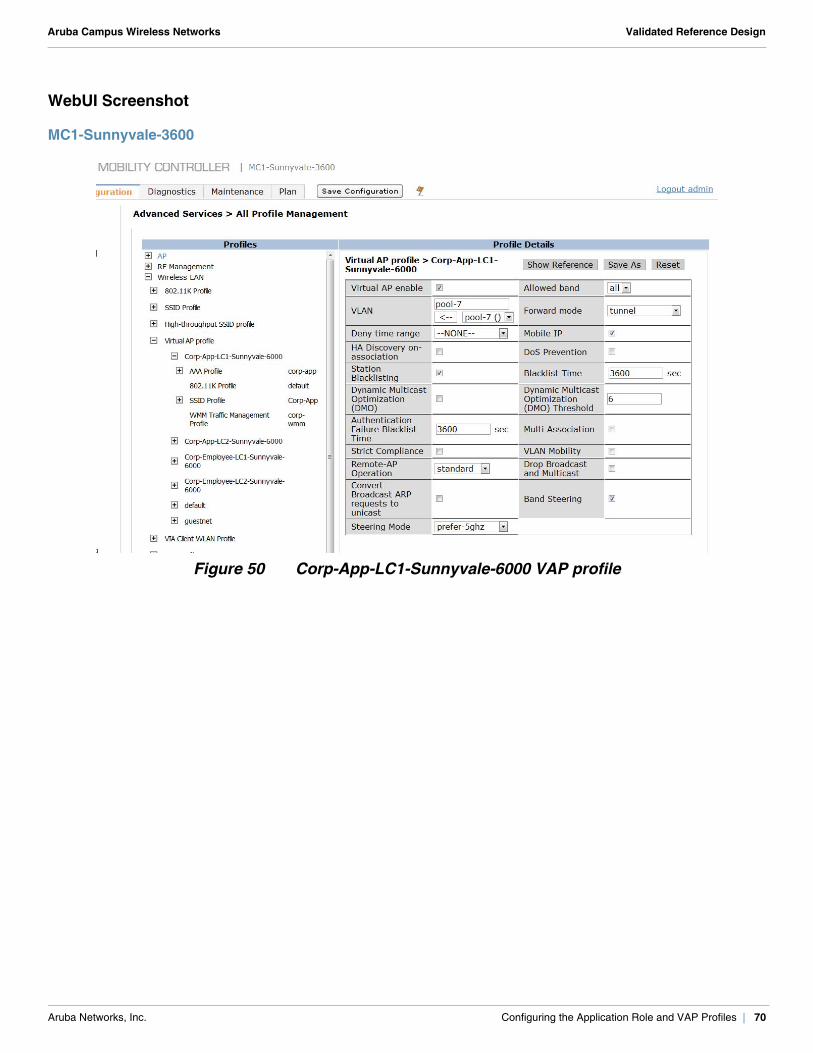
Aruba Campus Wireless Networks Validated Reference Design
WebUI Screenshot
MC1-Sunnyvale-3600
Figure 50 Corp-App-LC1-Sunnyvale-6000 VAP profile
Aruba Networks, Inc. Configuring the Application Role and VAP Profiles | 70
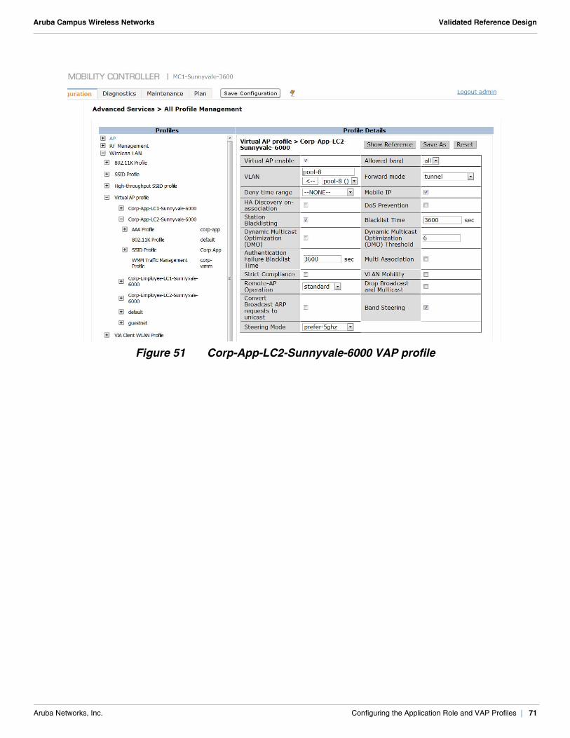
Aruba Campus Wireless Networks Validated Reference Design
Figure 51 Corp-App-LC2-Sunnyvale-6000 VAP profile
Aruba Networks, Inc. Configuring the Application Role and VAP Profiles | 71

Aruba Campus Wireless Networks Validated Reference Design
Aruba Networks, Inc. Configuring the Application Role and VAP Profiles | 72
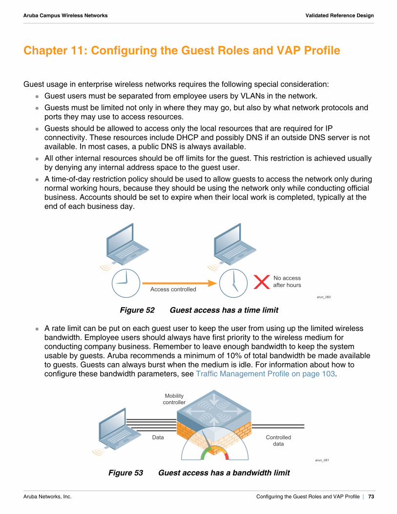
Aruba Campus Wireless Networks Validated Reference Design
Chapter 11: Configuring the Guest Roles and VAP Profile
Guest usage in enterprise wireless networks requires the following special consideration: Guest users must be separated from employee users by VLANs in the network. Guests must be limited not only in where they may go, but also by what network protocols and
ports they may use to access resources. Guests should be allowed to access only the local resources that are required for IP
connectivity. These resources include DHCP and possibly DNS if an outside DNS server is not available. In most cases, a public DNS is always available.
All other internal resources should be off limits for the guest. This restriction is achieved usually by denying any internal address space to the guest user.
A time-of-day restriction policy should be used to allow guests to access the network only during normal working hours, because they should be using the network only while conducting official business. Accounts should be set to expire when their local work is completed, typically at the end of each business day.
Figure 52 Guest access has a time limit
A rate limit can be put on each guest user to keep the user from using up the limited wireless bandwidth. Employee users should always have first priority to the wireless medium for conducting company business. Remember to leave enough bandwidth to keep the system usable by guests. Aruba recommends a minimum of 10% of total bandwidth be made available to guests. Guests can always burst when the medium is idle. For information about how to configure these bandwidth parameters, see Traffic Management Profile on page 103.
Figure 53 Guest access has a bandwidth limit
arun_060
No accessafter hours
Access controlled
arun_061
Mobilitycontroller
Data Controlleddata
Aruba Networks, Inc. Configuring the Guest Roles and VAP Profile | 73
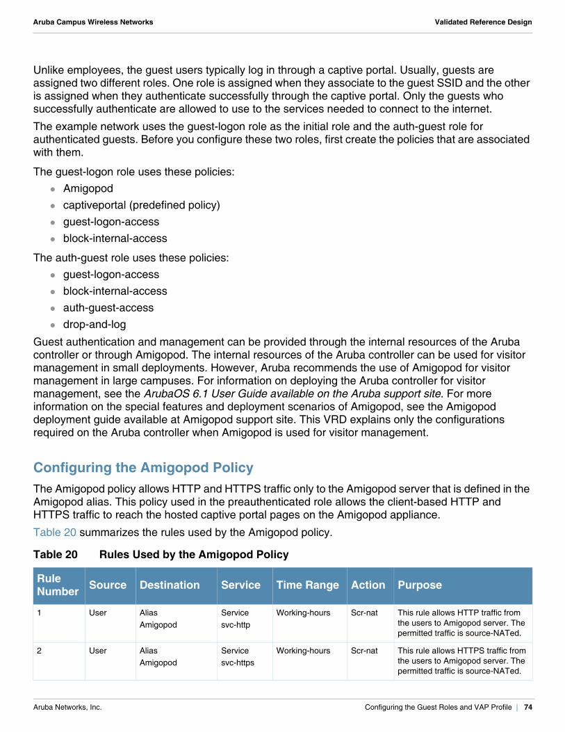
Aruba Campus Wireless Networks Validated Reference Design
Unlike employees, the guest users typically log in through a captive portal. Usually, guests are assigned two different roles. One role is assigned when they associate to the guest SSID and the other is assigned when they authenticate successfully through the captive portal. Only the guests who successfully authenticate are allowed to use to the services needed to connect to the internet.
The example network uses the guest-logon role as the initial role and the auth-guest role for authenticated guests. Before you configure these two roles, first create the policies that are associated with them.
The guest-logon role uses these policies: Amigopod captiveportal (predefined policy) guest-logon-access block-internal-access
The auth-guest role uses these policies: guest-logon-access block-internal-access auth-guest-access drop-and-log
Guest authentication and management can be provided through the internal resources of the Aruba controller or through Amigopod. The internal resources of the Aruba controller can be used for visitor management in small deployments. However, Aruba recommends the use of Amigopod for visitor management in large campuses. For information on deploying the Aruba controller for visitor management, see the ArubaOS 6.1 User Guide available on the Aruba support site. For more information on the special features and deployment scenarios of Amigopod, see the Amigopod deployment guide available at Amigopod support site. This VRD explains only the configurations required on the Aruba controller when Amigopod is used for visitor management.
Configuring the Amigopod PolicyThe Amigopod policy allows HTTP and HTTPS traffic only to the Amigopod server that is defined in the Amigopod alias. This policy used in the preauthenticated role allows the client-based HTTP and HTTPS traffic to reach the hosted captive portal pages on the Amigopod appliance.
Table 20 summarizes the rules used by the Amigopod policy.
Table 20 Rules Used by the Amigopod Policy
Rule Number Source Destination Service Time Range Action Purpose
1 User AliasAmigopod
Servicesvc-http
Working-hours Scr-nat This rule allows HTTP traffic from the users to Amigopod server. The permitted traffic is source-NATed.
2 User AliasAmigopod
Servicesvc-https
Working-hours Scr-nat This rule allows HTTPS traffic from the users to Amigopod server. The permitted traffic is source-NATed.
Aruba Networks, Inc. Configuring the Guest Roles and VAP Profile | 74
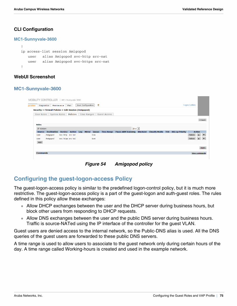
Aruba Campus Wireless Networks Validated Reference Design
CLI Configuration
MC1-Sunnyvale-3600!
ip access-list session Amigopod
user alias Amigopod svc-http src-nat
user alias Amigopod svc-https src-nat
!
WebUI Screenshot
MC1-Sunnyvale-3600
Figure 54 Amigopod policy
Configuring the guest-logon-access PolicyThe guest-logon-access policy is similar to the predefined logon-control policy, but it is much more restrictive. The guest-logon-access policy is a part of the guest-logon and auth-guest roles. The rules defined in this policy allow these exchanges:
Allow DHCP exchanges between the user and the DHCP server during business hours, but block other users from responding to DHCP requests.
Allow DNS exchanges between the user and the public DNS server during business hours. Traffic is source-NATed using the IP interface of the controller for the guest VLAN.
Guest users are denied access to the internal network, so the Public-DNS alias is used. All the DNS queries of the guest users are forwarded to these public DNS servers.
A time range is used to allow users to associate to the guest network only during certain hours of the day. A time range called Working-hours is created and used in the example network.
Aruba Networks, Inc. Configuring the Guest Roles and VAP Profile | 75
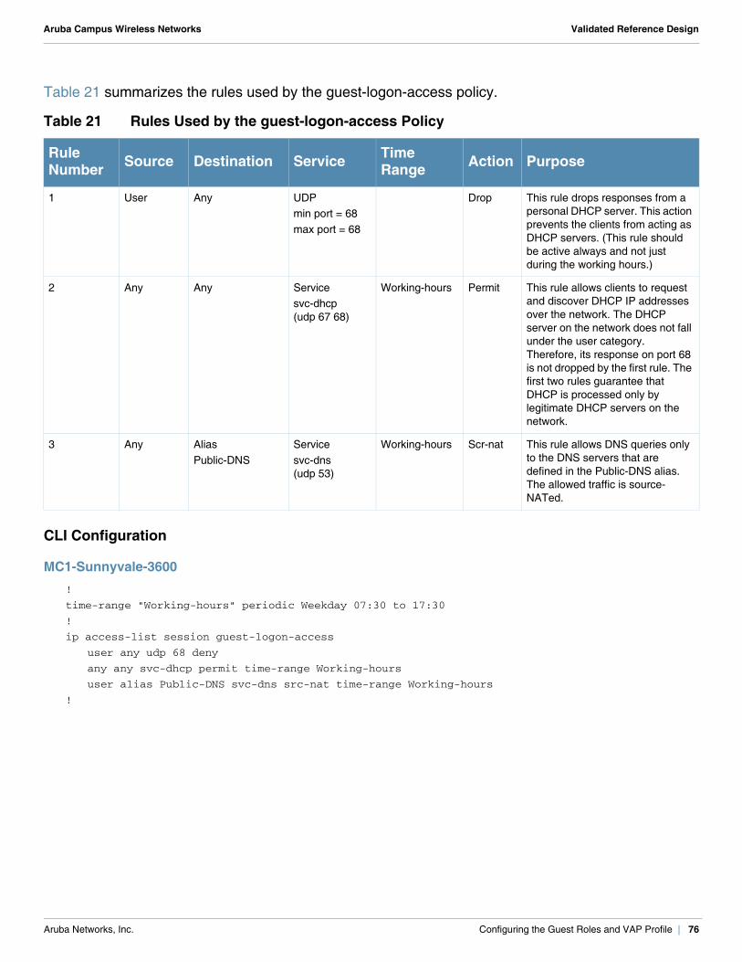
Aruba Campus Wireless Networks Validated Reference Design
Table 21 summarizes the rules used by the guest-logon-access policy.
CLI Configuration
MC1-Sunnyvale-3600!
time-range "Working-hours" periodic Weekday 07:30 to 17:30
!
ip access-list session guest-logon-access
user any udp 68 deny
any any svc-dhcp permit time-range Working-hours
user alias Public-DNS svc-dns src-nat time-range Working-hours
!
Table 21 Rules Used by the guest-logon-access Policy
Rule Number Source Destination Service Time
Range Action Purpose
1 User Any UDP min port = 68max port = 68
Drop This rule drops responses from a personal DHCP server. This action prevents the clients from acting as DHCP servers. (This rule should be active always and not just during the working hours.)
2 Any Any Servicesvc-dhcp (udp 67 68)
Working-hours Permit This rule allows clients to request and discover DHCP IP addresses over the network. The DHCP server on the network does not fall under the user category. Therefore, its response on port 68 is not dropped by the first rule. The first two rules guarantee that DHCP is processed only by legitimate DHCP servers on the network.
3 Any AliasPublic-DNS
Service svc-dns (udp 53)
Working-hours Scr-nat This rule allows DNS queries only to the DNS servers that are defined in the Public-DNS alias. The allowed traffic is source-NATed.
Aruba Networks, Inc. Configuring the Guest Roles and VAP Profile | 76
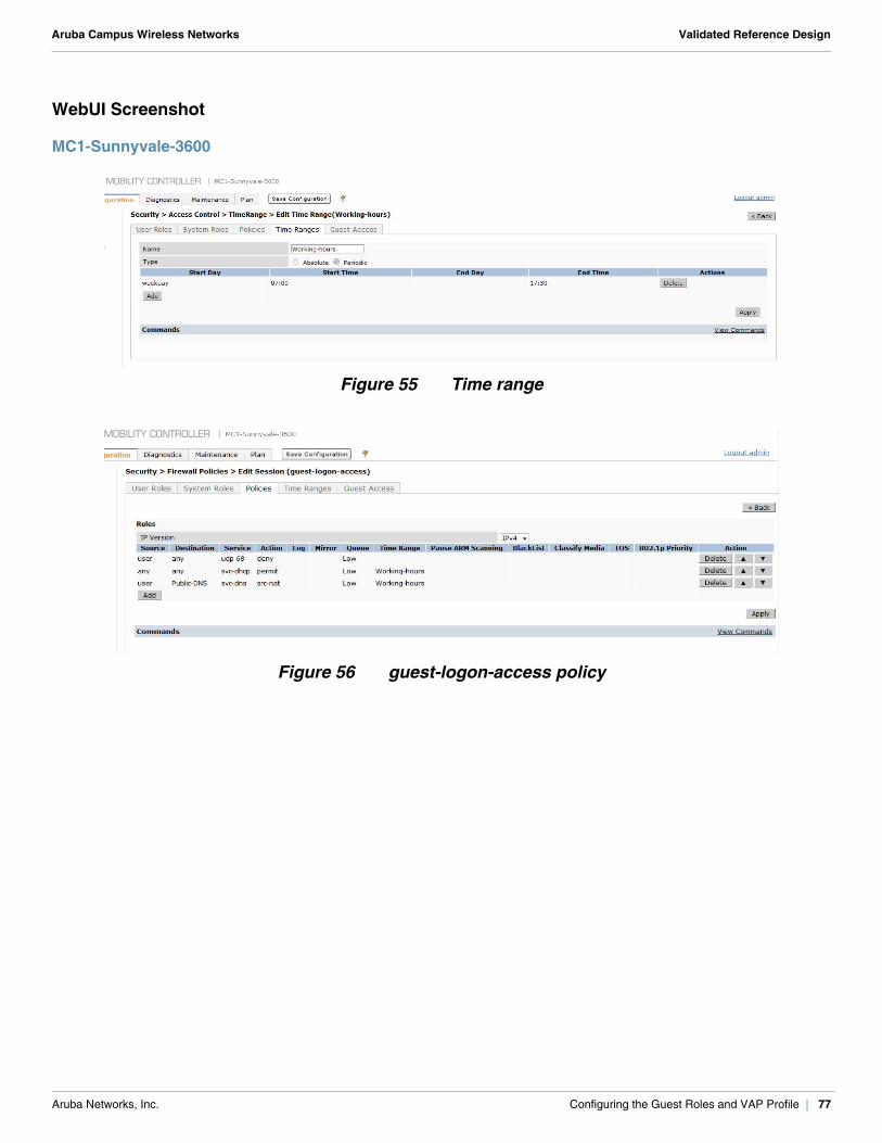
Aruba Campus Wireless Networks Validated Reference Design
WebUI Screenshot
MC1-Sunnyvale-3600
Figure 55 Time range
Figure 56 guest-logon-access policy
Aruba Networks, Inc. Configuring the Guest Roles and VAP Profile | 77
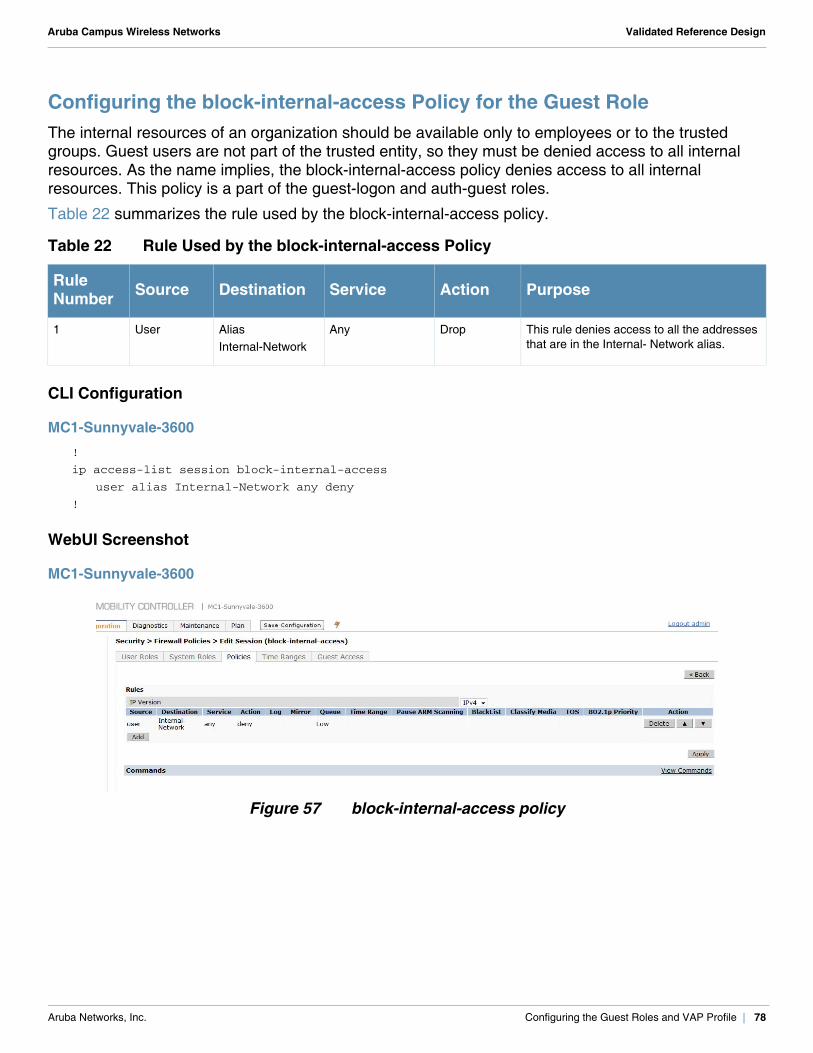
Aruba Campus Wireless Networks Validated Reference Design
Configuring the block-internal-access Policy for the Guest RoleThe internal resources of an organization should be available only to employees or to the trusted groups. Guest users are not part of the trusted entity, so they must be denied access to all internal resources. As the name implies, the block-internal-access policy denies access to all internal resources. This policy is a part of the guest-logon and auth-guest roles.
Table 22 summarizes the rule used by the block-internal-access policy.
CLI Configuration
MC1-Sunnyvale-3600!
ip access-list session block-internal-access
user alias Internal-Network any deny
!
WebUI Screenshot
MC1-Sunnyvale-3600
Figure 57 block-internal-access policy
Table 22 Rule Used by the block-internal-access Policy
Rule Number Source Destination Service Action Purpose
1 User AliasInternal-Network
Any Drop This rule denies access to all the addresses that are in the Internal- Network alias.
Aruba Networks, Inc. Configuring the Guest Roles and VAP Profile | 78
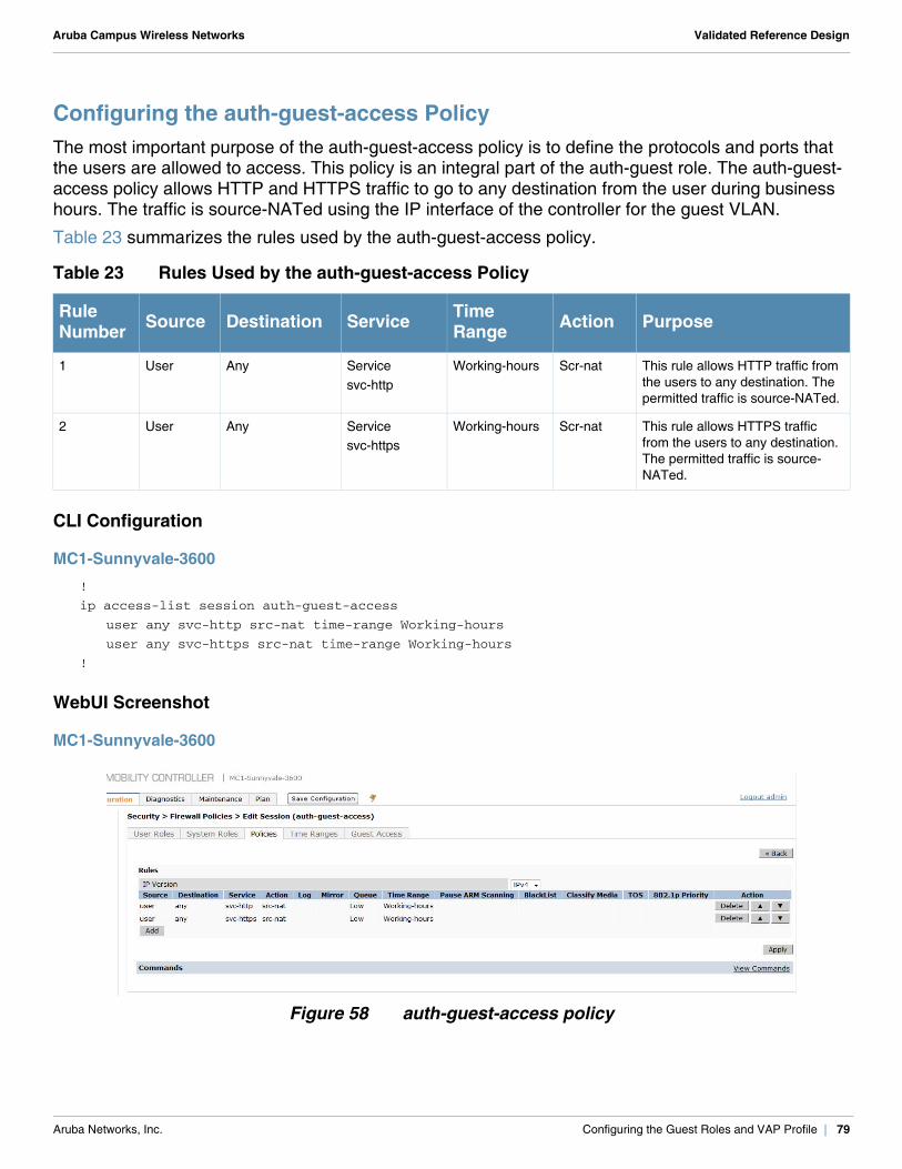
Aruba Campus Wireless Networks Validated Reference Design
Configuring the auth-guest-access PolicyThe most important purpose of the auth-guest-access policy is to define the protocols and ports that the users are allowed to access. This policy is an integral part of the auth-guest role. The auth-guest-access policy allows HTTP and HTTPS traffic to go to any destination from the user during business hours. The traffic is source-NATed using the IP interface of the controller for the guest VLAN.
Table 23 summarizes the rules used by the auth-guest-access policy.
CLI Configuration
MC1-Sunnyvale-3600!
ip access-list session auth-guest-access
user any svc-http src-nat time-range Working-hours
user any svc-https src-nat time-range Working-hours
!
WebUI Screenshot
MC1-Sunnyvale-3600
Figure 58 auth-guest-access policy
Table 23 Rules Used by the auth-guest-access Policy
Rule Number Source Destination Service Time
Range Action Purpose
1 User Any Servicesvc-http
Working-hours Scr-nat This rule allows HTTP traffic from the users to any destination. The permitted traffic is source-NATed.
2 User Any Servicesvc-https
Working-hours Scr-nat This rule allows HTTPS traffic from the users to any destination. The permitted traffic is source-NATed.
Aruba Networks, Inc. Configuring the Guest Roles and VAP Profile | 79
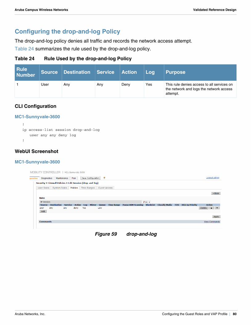
Aruba Campus Wireless Networks Validated Reference Design
Configuring the drop-and-log PolicyThe drop-and-log policy denies all traffic and records the network access attempt.
Table 24 summarizes the rule used by the drop-and-log policy.
CLI Configuration
MC1-Sunnyvale-3600!
ip access-list session drop-and-log
user any any deny log
!
WebUI Screenshot
MC1-Sunnyvale-3600
Figure 59 drop-and-log
Table 24 Rule Used by the drop-and-log Policy
Rule Number Source Destination Service Action Log Purpose
1 User Any Any Deny Yes This rule denies access to all services on the network and logs the network access attempt.
Aruba Networks, Inc. Configuring the Guest Roles and VAP Profile | 80
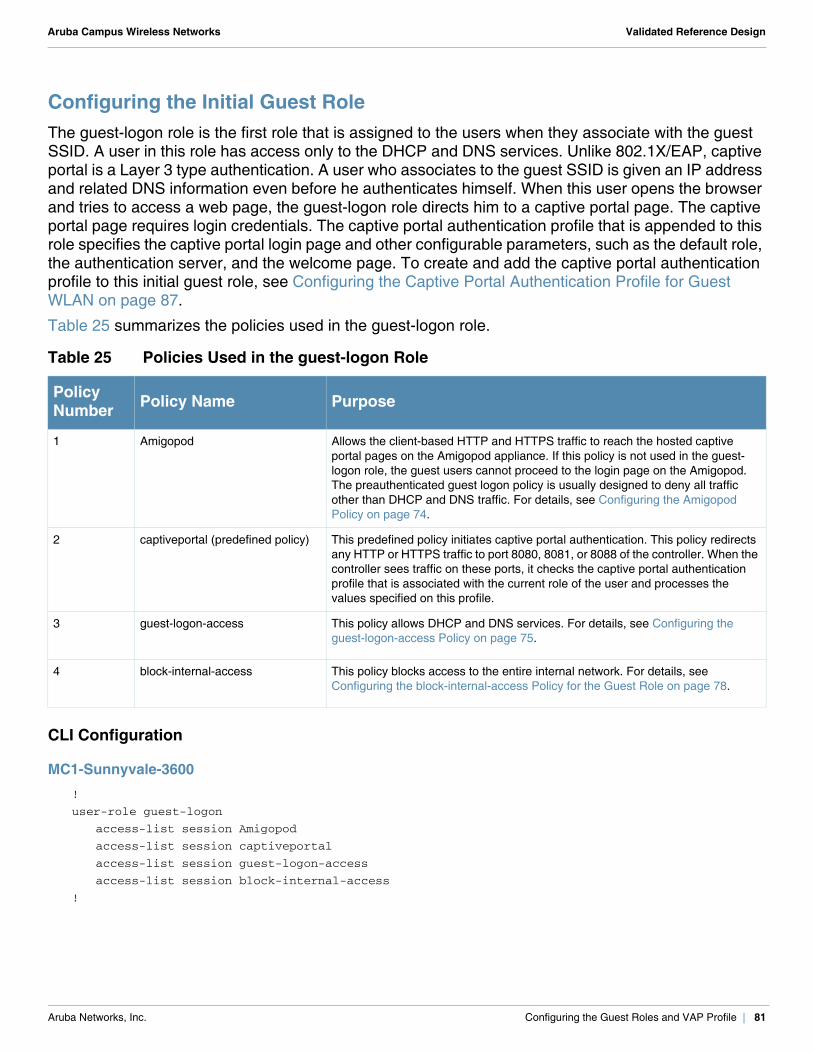
Aruba Campus Wireless Networks Validated Reference Design
Configuring the Initial Guest RoleThe guest-logon role is the first role that is assigned to the users when they associate with the guest SSID. A user in this role has access only to the DHCP and DNS services. Unlike 802.1X/EAP, captive portal is a Layer 3 type authentication. A user who associates to the guest SSID is given an IP address and related DNS information even before he authenticates himself. When this user opens the browser and tries to access a web page, the guest-logon role directs him to a captive portal page. The captive portal page requires login credentials. The captive portal authentication profile that is appended to this role specifies the captive portal login page and other configurable parameters, such as the default role, the authentication server, and the welcome page. To create and add the captive portal authentication profile to this initial guest role, see Configuring the Captive Portal Authentication Profile for Guest WLAN on page 87.
Table 25 summarizes the policies used in the guest-logon role.
CLI Configuration
MC1-Sunnyvale-3600!
user-role guest-logon
access-list session Amigopod
access-list session captiveportal
access-list session guest-logon-access
access-list session block-internal-access
!
Table 25 Policies Used in the guest-logon Role
Policy Number Policy Name Purpose
1 Amigopod Allows the client-based HTTP and HTTPS traffic to reach the hosted captive portal pages on the Amigopod appliance. If this policy is not used in the guest-logon role, the guest users cannot proceed to the login page on the Amigopod. The preauthenticated guest logon policy is usually designed to deny all traffic other than DHCP and DNS traffic. For details, see Configuring the Amigopod Policy on page 74.
2 captiveportal (predefined policy) This predefined policy initiates captive portal authentication. This policy redirects any HTTP or HTTPS traffic to port 8080, 8081, or 8088 of the controller. When the controller sees traffic on these ports, it checks the captive portal authentication profile that is associated with the current role of the user and processes the values specified on this profile.
3 guest-logon-access This policy allows DHCP and DNS services. For details, see Configuring the guest-logon-access Policy on page 75.
4 block-internal-access This policy blocks access to the entire internal network. For details, see Configuring the block-internal-access Policy for the Guest Role on page 78.
Aruba Networks, Inc. Configuring the Guest Roles and VAP Profile | 81
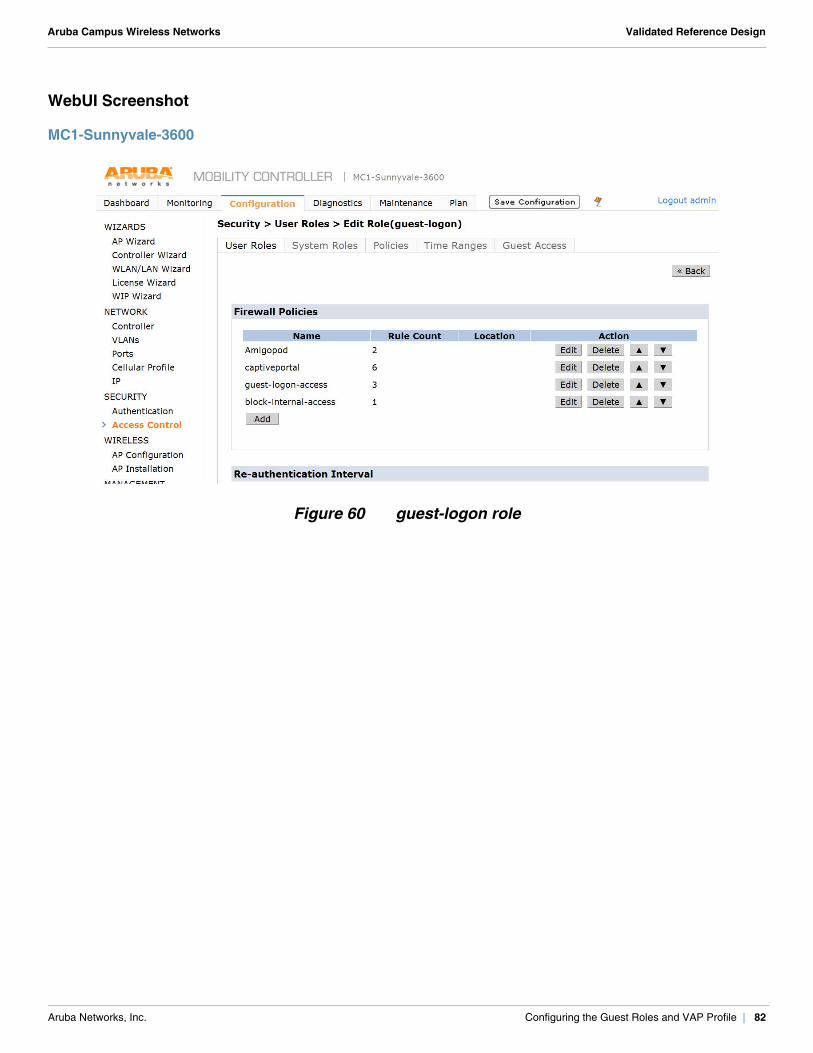
Aruba Campus Wireless Networks Validated Reference Design
WebUI Screenshot
MC1-Sunnyvale-3600
Figure 60 guest-logon role
Aruba Networks, Inc. Configuring the Guest Roles and VAP Profile | 82
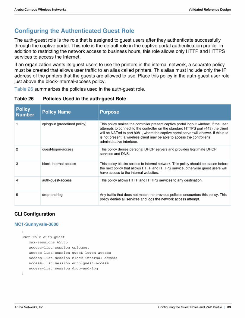
Aruba Campus Wireless Networks Validated Reference Design
Configuring the Authenticated Guest RoleThe auth-guest role is the role that is assigned to guest users after they authenticate successfully through the captive portal. This role is the default role in the captive portal authentication profile. In addition to restricting the network access to business hours, this role allows only HTTP and HTTPS services to access the Internet.
If an organization wants its guest users to use the printers in the internal network, a separate policy must be created that allows user traffic to an alias called printers. This alias must include only the IP address of the printers that the guests are allowed to use. Place this policy in the auth-guest user role just above the block-internal-access policy.
Table 26 summarizes the policies used in the auth-guest role.
CLI Configuration
MC1-Sunnyvale-3600!
user-role auth-guest
max-sessions 65535
access-list session cplogout
access-list session guest-logon-access
access-list session block-internal-access
access-list session auth-guest-access
access-list session drop-and-log
!
Table 26 Policies Used in the auth-guest Role
Policy Number Policy Name Purpose
1 cplogout (predefined policy) This policy makes the controller present captive portal logout window. If the user attempts to connect to the controller on the standard HTTPS port (443) the client will be NATed to port 8081, where the captive portal server will answer. If this rule is not present, a wireless client may be able to access the controller's administrative interface.
2 guest-logon-access This policy denies personal DHCP servers and provides legitimate DHCP services and DNS.
3 block-internal-access This policy blocks access to internal network. This policy should be placed before the next policy that allows HTTP and HTTPS service, otherwise guest users will have access to the internal websites.
4 auth-guest-access This policy allows HTTP and HTTPS services to any destination.
5 drop-and-log Any traffic that does not match the previous policies encounters this policy. This policy denies all services and logs the network access attempt.
Aruba Networks, Inc. Configuring the Guest Roles and VAP Profile | 83
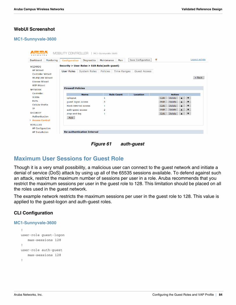
Aruba Campus Wireless Networks Validated Reference Design
WebUI Screenshot
MC1-Sunnyvale-3600
Figure 61 auth-guest
Maximum User Sessions for Guest RoleThough it is a very small possibility, a malicious user can connect to the guest network and initiate a denial of service (DoS) attack by using up all of the 65535 sessions available. To defend against such an attack, restrict the maximum number of sessions per user in a role. Aruba recommends that you restrict the maximum sessions per user in the guest role to 128. This limitation should be placed on all the roles used in the guest network.
The example network restricts the maximum sessions per user in the guest role to 128. This value is applied to the guest-logon and auth-guest roles.
CLI Configuration
MC1-Sunnyvale-3600!
user-role guest-logon
max-sessions 128
!
user-role auth-guest
max-sessions 128
!
Aruba Networks, Inc. Configuring the Guest Roles and VAP Profile | 84
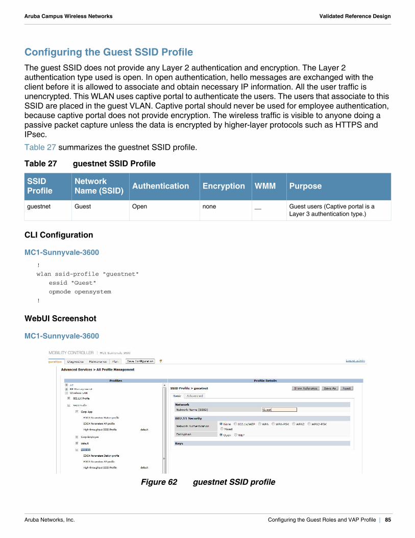
Aruba Campus Wireless Networks Validated Reference Design
Configuring the Guest SSID Profile The guest SSID does not provide any Layer 2 authentication and encryption. The Layer 2 authentication type used is open. In open authentication, hello messages are exchanged with the client before it is allowed to associate and obtain necessary IP information. All the user traffic is unencrypted. This WLAN uses captive portal to authenticate the users. The users that associate to this SSID are placed in the guest VLAN. Captive portal should never be used for employee authentication, because captive portal does not provide encryption. The wireless traffic is visible to anyone doing a passive packet capture unless the data is encrypted by higher-layer protocols such as HTTPS and IPsec.
Table 27 summarizes the guestnet SSID profile.
CLI Configuration
MC1-Sunnyvale-3600!
wlan ssid-profile "guestnet"
essid "Guest"
opmode opensystem
!
WebUI Screenshot
MC1-Sunnyvale-3600
Figure 62 guestnet SSID profile
Table 27 guestnet SSID Profile
SSIDProfile
NetworkName (SSID) Authentication Encryption WMM Purpose
guestnet Guest Open none __ Guest users (Captive portal is a Layer 3 authentication type.)
Aruba Networks, Inc. Configuring the Guest Roles and VAP Profile | 85
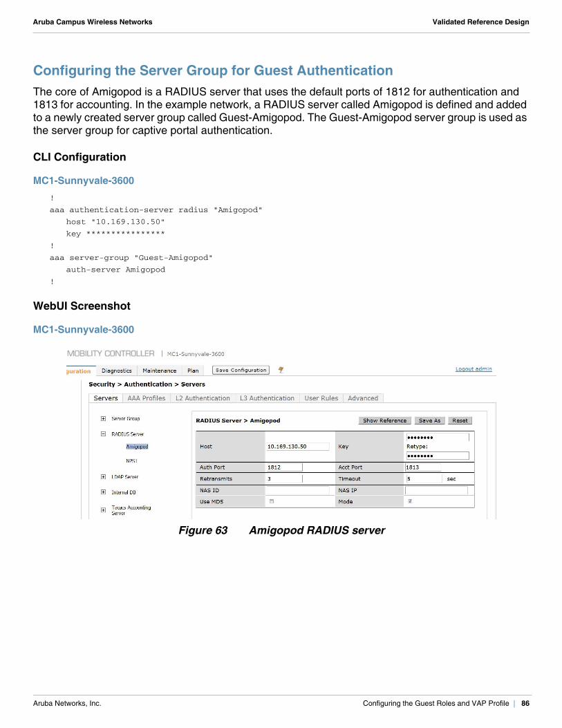
Aruba Campus Wireless Networks Validated Reference Design
Configuring the Server Group for Guest AuthenticationThe core of Amigopod is a RADIUS server that uses the default ports of 1812 for authentication and 1813 for accounting. In the example network, a RADIUS server called Amigopod is defined and added to a newly created server group called Guest-Amigopod. The Guest-Amigopod server group is used as the server group for captive portal authentication.
CLI Configuration
MC1-Sunnyvale-3600!
aaa authentication-server radius "Amigopod"
host "10.169.130.50"
key ****************
!
aaa server-group "Guest-Amigopod"
auth-server Amigopod
!
WebUI Screenshot
MC1-Sunnyvale-3600
Figure 63 Amigopod RADIUS server
Aruba Networks, Inc. Configuring the Guest Roles and VAP Profile | 86
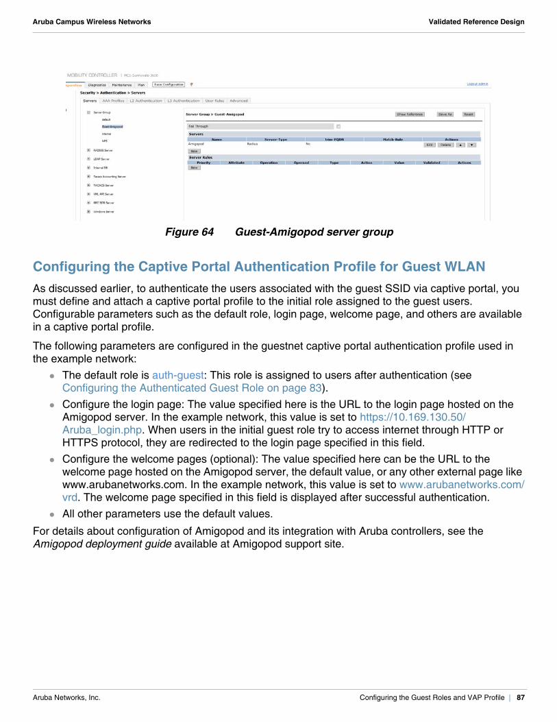
Aruba Campus Wireless Networks Validated Reference Design
Figure 64 Guest-Amigopod server group
Configuring the Captive Portal Authentication Profile for Guest WLANAs discussed earlier, to authenticate the users associated with the guest SSID via captive portal, you must define and attach a captive portal profile to the initial role assigned to the guest users. Configurable parameters such as the default role, login page, welcome page, and others are available in a captive portal profile.
The following parameters are configured in the guestnet captive portal authentication profile used in the example network:
The default role is auth-guest: This role is assigned to users after authentication (see Configuring the Authenticated Guest Role on page 83).
Configure the login page: The value specified here is the URL to the login page hosted on the Amigopod server. In the example network, this value is set to https://10.169.130.50/Aruba_login.php. When users in the initial guest role try to access internet through HTTP or HTTPS protocol, they are redirected to the login page specified in this field.
Configure the welcome pages (optional): The value specified here can be the URL to the welcome page hosted on the Amigopod server, the default value, or any other external page like www.arubanetworks.com. In the example network, this value is set to www.arubanetworks.com/vrd. The welcome page specified in this field is displayed after successful authentication.
All other parameters use the default values.
For details about configuration of Amigopod and its integration with Aruba controllers, see the Amigopod deployment guide available at Amigopod support site.
Aruba Networks, Inc. Configuring the Guest Roles and VAP Profile | 87
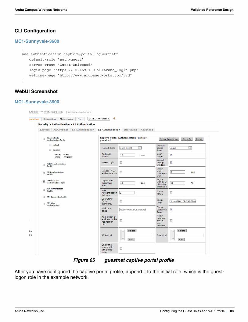
Aruba Campus Wireless Networks Validated Reference Design
CLI Configuration
MC1-Sunnyvale-3600 !
aaa authentication captive-portal "guestnet"
default-role "auth-guest"
server-group "Guest-Amigopod"
login-page "https://10.169.130.50/Aruba_login.php"
welcome-page "http://www.arubanetworks.com/vrd"
!
WebUI Screenshot
MC1-Sunnyvale-3600
Figure 65 guestnet captive portal profile
After you have configured the captive portal profile, append it to the initial role, which is the guest-logon role in the example network.
Aruba Networks, Inc. Configuring the Guest Roles and VAP Profile | 88
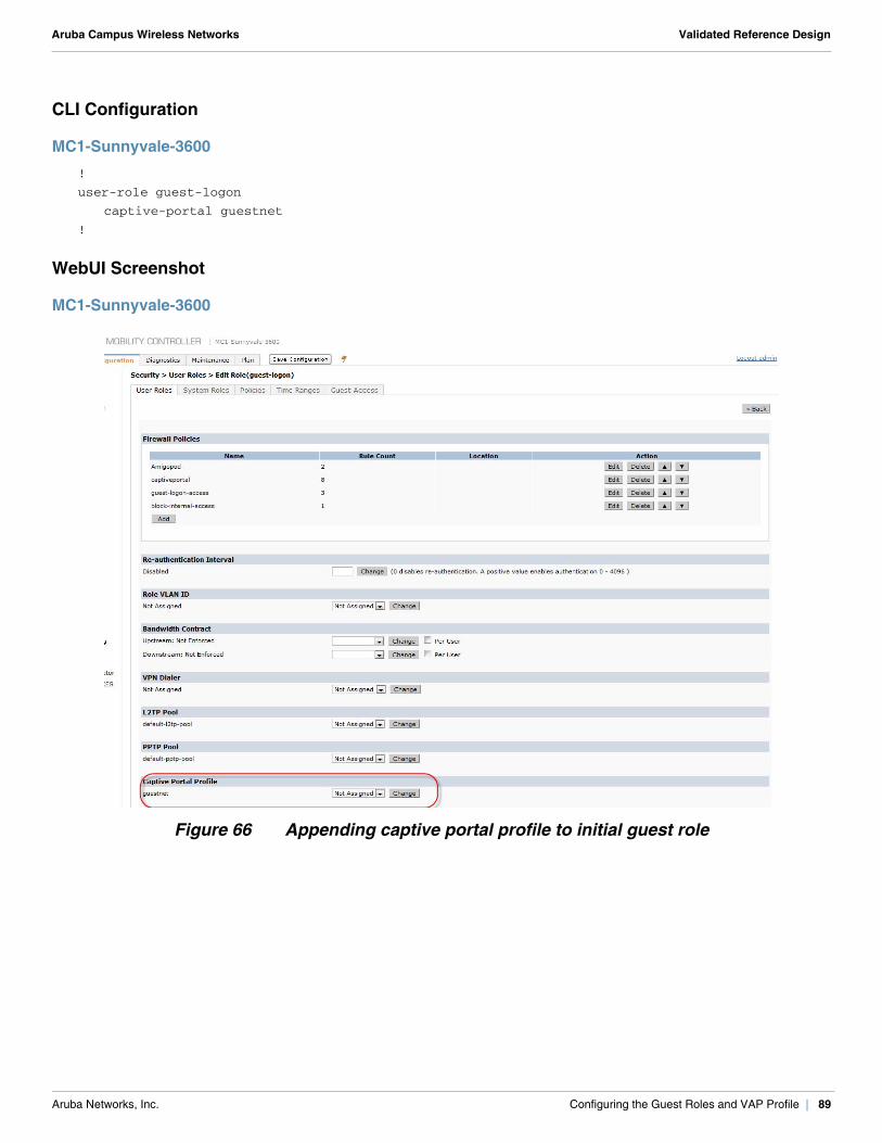
Aruba Campus Wireless Networks Validated Reference Design
CLI Configuration
MC1-Sunnyvale-3600!
user-role guest-logon
captive-portal guestnet
!
WebUI Screenshot
MC1-Sunnyvale-3600
Figure 66 Appending captive portal profile to initial guest role
Aruba Networks, Inc. Configuring the Guest Roles and VAP Profile | 89
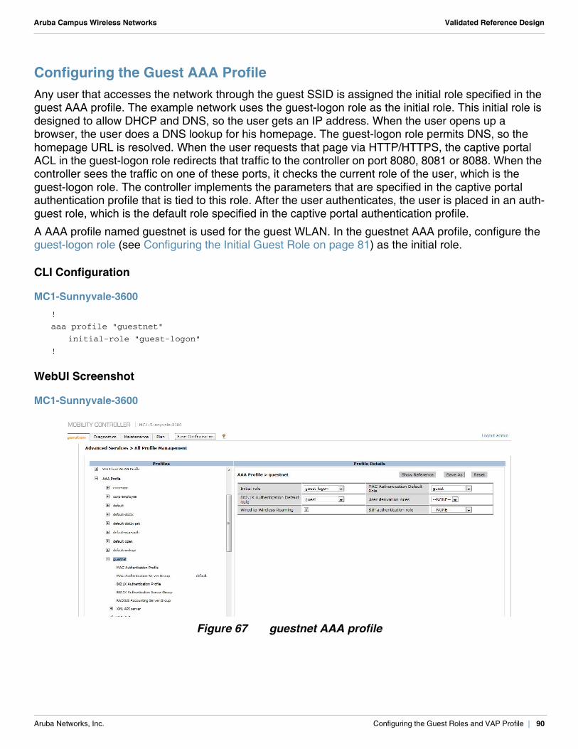
Aruba Campus Wireless Networks Validated Reference Design
Configuring the Guest AAA ProfileAny user that accesses the network through the guest SSID is assigned the initial role specified in the guest AAA profile. The example network uses the guest-logon role as the initial role. This initial role is designed to allow DHCP and DNS, so the user gets an IP address. When the user opens up a browser, the user does a DNS lookup for his homepage. The guest-logon role permits DNS, so the homepage URL is resolved. When the user requests that page via HTTP/HTTPS, the captive portal ACL in the guest-logon role redirects that traffic to the controller on port 8080, 8081 or 8088. When the controller sees the traffic on one of these ports, it checks the current role of the user, which is the guest-logon role. The controller implements the parameters that are specified in the captive portal authentication profile that is tied to this role. After the user authenticates, the user is placed in an auth-guest role, which is the default role specified in the captive portal authentication profile.
A AAA profile named guestnet is used for the guest WLAN. In the guestnet AAA profile, configure the guest-logon role (see Configuring the Initial Guest Role on page 81) as the initial role.
CLI Configuration
MC1-Sunnyvale-3600!
aaa profile "guestnet"
initial-role "guest-logon"
!
WebUI Screenshot
MC1-Sunnyvale-3600
Figure 67 guestnet AAA profile
Aruba Networks, Inc. Configuring the Guest Roles and VAP Profile | 90
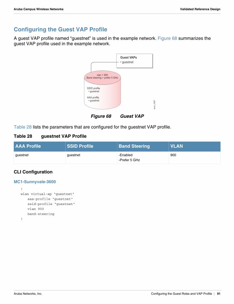
Aruba Campus Wireless Networks Validated Reference Design
Configuring the Guest VAP ProfileA guest VAP profile named “guestnet” is used in the example network. Figure 68 summarizes the guest VAP profile used in the example network.
Figure 68 Guest VAP
Table 28 lists the parameters that are configured for the guestnet VAP profile.
CLI Configuration
MC1-Sunnyvale-3600!
wlan virtual-ap "guestnet"
aaa-profile "guestnet"
ssid-profile "guestnet"
vlan 900
band-steering
!
Table 28 guestnet VAP Profile
AAA Profile SSID Profile Band Steering VLAN
guestnet guestnet -Enabled-Prefer 5 GHz
900
SSID profile • guestnet
AAA profile • guestnet
arun_0387
Guest VAPs• guestnet
vlan = 900Band steering = prefer 5 GHz
Aruba Networks, Inc. Configuring the Guest Roles and VAP Profile | 91
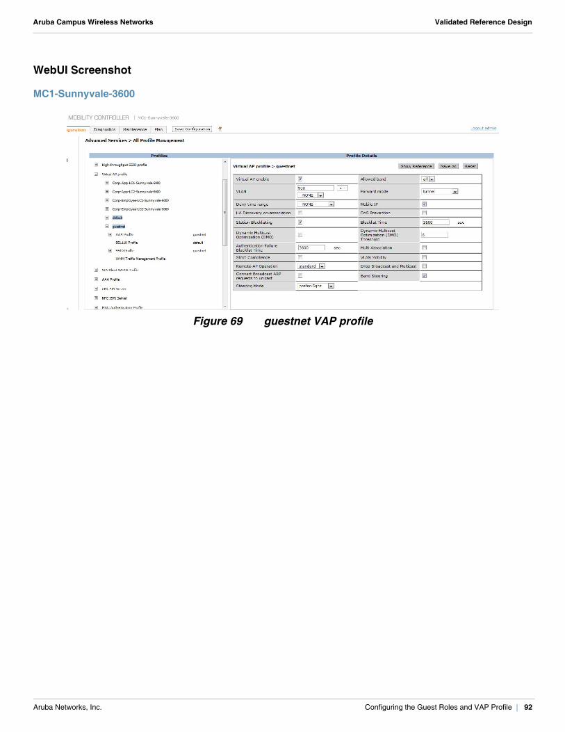
Aruba Campus Wireless Networks Validated Reference Design
WebUI Screenshot
MC1-Sunnyvale-3600
Figure 69 guestnet VAP profile
Aruba Networks, Inc. Configuring the Guest Roles and VAP Profile | 92
Aruba Campus Wireless Networks Validated Reference Design
Chapter 12: Configuring the Radio Profiles
The 802.11a and 802.11g radio profiles form the core of RF management. The various profiles and options under RF management allow you to configure these things:
radio tuning and calibration AP load balancing coverage hole detection received signal strength indicator (RSSI) metrics
Primarily, the 802.11a and 802.11g radio profiles determine the mode in which an AP radio operates. A radio can be made to operate in one of the following three predefined modes:
ap-mode (for typical APs) am-mode (for AMs) spectrum-mode (for SMs)
The 802.11a and 802.11g profiles are independent of each other. So, a dual-radio AP can be configured to behave as an AM in one spectrum band and function as a regular AP in the other band. In addition to the basic radio settings, the 802.11a and 802.11g radio profiles within an AP group include these profiles:
ARM profile (required only for client access APs) high-throughput radio profile spectrum profile (required only for dedicated SMs) AM scanning profile (required only for AMs)
Configuring the ARM Profile The Aruba Adaptive Radio Management (ARM) feature is a set of tools that allow the WLAN infrastructure to make decisions about radio resources and client connections without manual intervention by network administrators or client-side software.
The ARM algorithms and services use the information that APs and AMs gather when they scan the RF environment. The infrastructure has a network-wide view of APs and clients, and this information is used to make adjustments to provide an optimal client experience.
The Aruba ARM feature provides the following functionalities: channel and power setting client-aware ARM voice-aware scanning video-aware scanning rogue-aware scanning load-aware scanning band steering
Aruba Networks, Inc. Configuring the Radio Profiles | 93
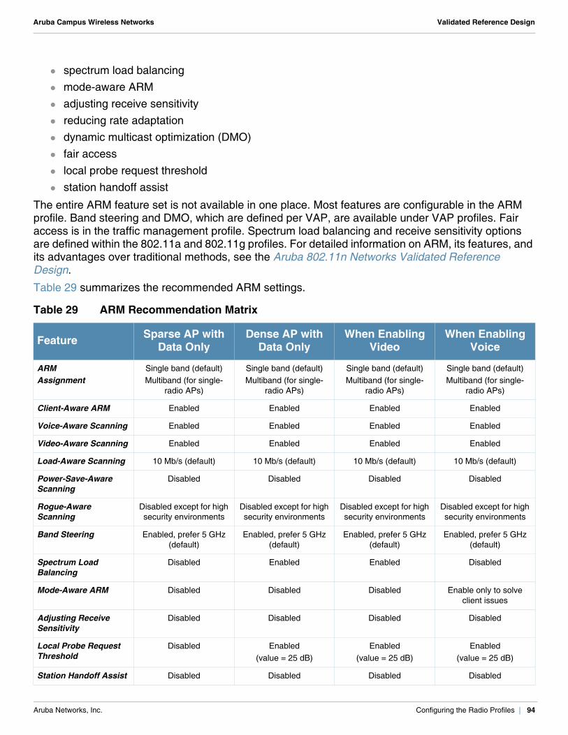
Aruba Campus Wireless Networks Validated Reference Design
spectrum load balancing mode-aware ARM adjusting receive sensitivity reducing rate adaptation dynamic multicast optimization (DMO) fair access local probe request threshold station handoff assist
The entire ARM feature set is not available in one place. Most features are configurable in the ARM profile. Band steering and DMO, which are defined per VAP, are available under VAP profiles. Fair access is in the traffic management profile. Spectrum load balancing and receive sensitivity options are defined within the 802.11a and 802.11g profiles. For detailed information on ARM, its features, and its advantages over traditional methods, see the Aruba 802.11n Networks Validated Reference Design.
Table 29 summarizes the recommended ARM settings.
Table 29 ARM Recommendation Matrix
Feature Sparse AP with Data Only
Dense AP with Data Only
When Enabling Video
When Enabling Voice
ARMAssignment
Single band (default)Multiband (for single-
radio APs)
Single band (default)Multiband (for single-
radio APs)
Single band (default)Multiband (for single-
radio APs)
Single band (default)Multiband (for single-
radio APs)
Client-Aware ARM Enabled Enabled Enabled Enabled
Voice-Aware Scanning Enabled Enabled Enabled Enabled
Video-Aware Scanning Enabled Enabled Enabled Enabled
Load-Aware Scanning 10 Mb/s (default) 10 Mb/s (default) 10 Mb/s (default) 10 Mb/s (default)
Power-Save-Aware Scanning
Disabled Disabled Disabled Disabled
Rogue-Aware Scanning
Disabled except for high security environments
Disabled except for high security environments
Disabled except for high security environments
Disabled except for high security environments
Band Steering Enabled, prefer 5 GHz (default)
Enabled, prefer 5 GHz (default)
Enabled, prefer 5 GHz (default)
Enabled, prefer 5 GHz (default)
Spectrum Load Balancing
Disabled Enabled Enabled Disabled
Mode-Aware ARM Disabled Disabled Disabled Enable only to solve client issues
Adjusting Receive Sensitivity
Disabled Disabled Disabled Disabled
Local Probe Request Threshold
Disabled Enabled(value = 25 dB)
Enabled(value = 25 dB)
Enabled(value = 25 dB)
Station Handoff Assist Disabled Disabled Disabled Disabled
Aruba Networks, Inc. Configuring the Radio Profiles | 94
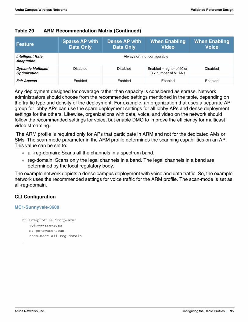
Aruba Campus Wireless Networks Validated Reference Design
Any deployment designed for coverage rather than capacity is considered as sprase. Network administrators should choose from the recommended settings mentioned in the table, depending on the traffic type and density of the deployment. For example, an organization that uses a separate AP group for lobby APs can use the spare deployment settings for all lobby APs and dense deployment settings for the others. Likewise, organizations with data, voice, and video on the network should follow the recommended settings for voice, but enable DMO to improve the efficiency for multicast video streaming.
The ARM profile is required only for APs that participate in ARM and not for the dedicated AMs or SMs. The scan-mode parameter in the ARM profile determines the scanning capabilities on an AP. This value can be set to:
all-reg-domain: Scans all the channels in a spectrum band. reg-domain: Scans only the legal channels in a band. The legal channels in a band are
determined by the local regulatory body.
The example network depicts a dense campus deployment with voice and data traffic. So, the example network uses the recommended settings for voice traffic for the ARM profile. The scan-mode is set as all-reg-domain.
CLI Configuration
MC1-Sunnyvale-3600!
rf arm-profile "corp-arm"
voip-aware-scan
no ps-aware-scan
scan-mode all-reg-domain
!
Intelligent Rate Adaptation
Always on, not configurable
Dynamic Multicast Optimization
Disabled Disabled Enabled – higher of 40 or 3 x number of VLANs
Disabled
Fair Access Enabled Enabled Enabled Enabled
Table 29 ARM Recommendation Matrix (Continued)
Feature Sparse AP with Data Only
Dense AP with Data Only
When Enabling Video
When Enabling Voice
Aruba Networks, Inc. Configuring the Radio Profiles | 95
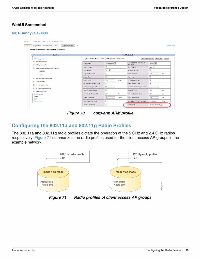
Aruba Campus Wireless Networks Validated Reference Design
WebUI Screenshot
MC1-Sunnyvale-3600
Figure 70 corp-arm ARM profile
Configuring the 802.11a and 802.11g Radio Profiles The 802.11a and 802.11g radio profiles dictate the operation of the 5 GHz and 2.4 GHz radios respectively. Figure 71 summarizes the radio profiles used for the client access AP groups in the example network.
Figure 71 Radio profiles of client access AP groups
802.11a radio profile• AP
mode = ap-mode
802.11g radio profile• AP
mode = ap-mode
ARM profile • corp-arm
ARM profile • corp-arm
arun_0365
Aruba Networks, Inc. Configuring the Radio Profiles | 96
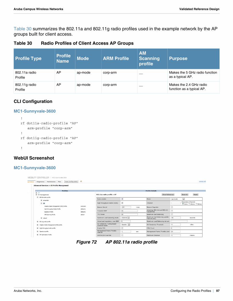
Aruba Campus Wireless Networks Validated Reference Design
Table 30 summarizes the 802.11a and 802.11g radio profiles used in the example network by the AP groups built for client access.
CLI Configuration
MC1-Sunnyvale-3600!
rf dot11a-radio-profile "AP"
arm-profile "corp-arm"
!
rf dot11g-radio-profile "AP"
arm-profile "corp-arm"
!
WebUI Screenshot
MC1-Sunnyvale-3600
Figure 72 AP 802.11a radio profile
Table 30 Radio Profiles of Client Access AP Groups
Profile Type Profile Name Mode ARM Profile
AM Scanning profile
Purpose
802.11a radioProfile
AP ap-mode corp-arm __ Makes the 5 GHz radio function as a typical AP.
802.11g radioProfile
AP ap-mode corp-arm __ Makes the 2.4 GHz radio function as a typical AP.
Aruba Networks, Inc. Configuring the Radio Profiles | 97
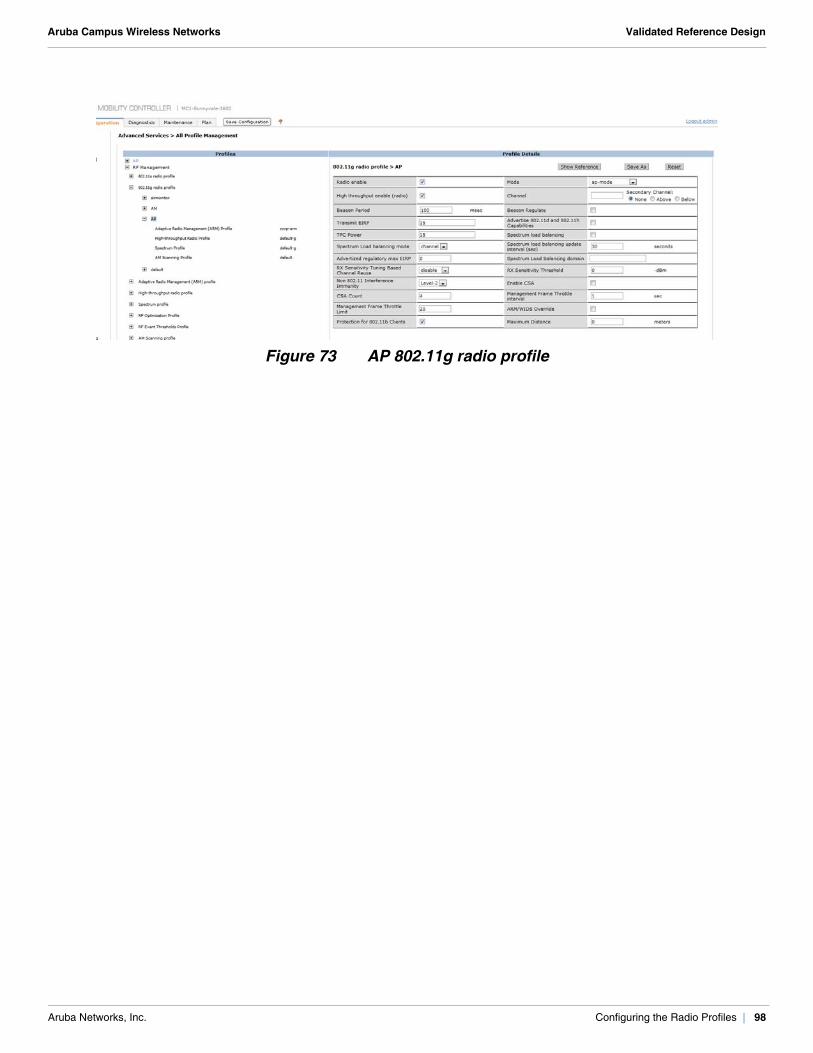
Aruba Campus Wireless Networks Validated Reference Design
Figure 73 AP 802.11g radio profile
Aruba Networks, Inc. Configuring the Radio Profiles | 98
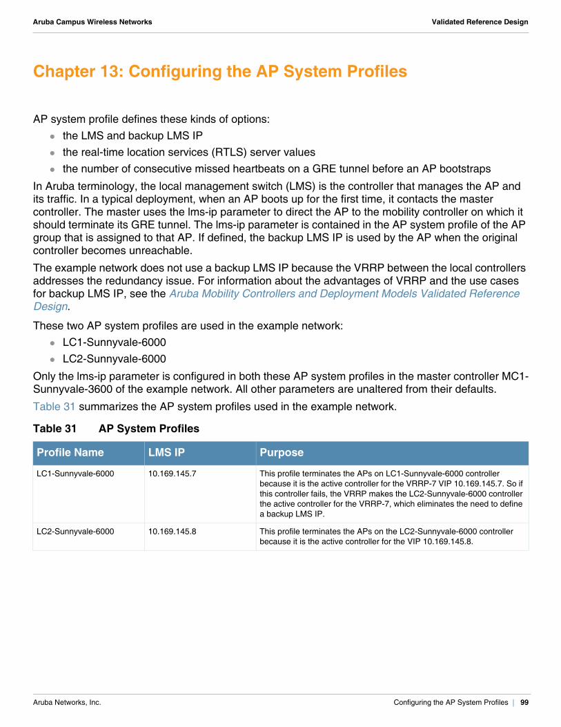
Aruba Campus Wireless Networks Validated Reference Design
Chapter 13: Configuring the AP System Profiles
AP system profile defines these kinds of options: the LMS and backup LMS IP the real-time location services (RTLS) server values the number of consecutive missed heartbeats on a GRE tunnel before an AP bootstraps
In Aruba terminology, the local management switch (LMS) is the controller that manages the AP and its traffic. In a typical deployment, when an AP boots up for the first time, it contacts the master controller. The master uses the lms-ip parameter to direct the AP to the mobility controller on which it should terminate its GRE tunnel. The lms-ip parameter is contained in the AP system profile of the AP group that is assigned to that AP. If defined, the backup LMS IP is used by the AP when the original controller becomes unreachable.
The example network does not use a backup LMS IP because the VRRP between the local controllers addresses the redundancy issue. For information about the advantages of VRRP and the use cases for backup LMS IP, see the Aruba Mobility Controllers and Deployment Models Validated Reference Design.
These two AP system profiles are used in the example network: LC1-Sunnyvale-6000 LC2-Sunnyvale-6000
Only the lms-ip parameter is configured in both these AP system profiles in the master controller MC1-Sunnyvale-3600 of the example network. All other parameters are unaltered from their defaults.
Table 31 summarizes the AP system profiles used in the example network.
Table 31 AP System Profiles
Profile Name LMS IP Purpose
LC1-Sunnyvale-6000 10.169.145.7 This profile terminates the APs on LC1-Sunnyvale-6000 controller because it is the active controller for the VRRP-7 VIP 10.169.145.7. So if this controller fails, the VRRP makes the LC2-Sunnyvale-6000 controller the active controller for the VRRP-7, which eliminates the need to define a backup LMS IP.
LC2-Sunnyvale-6000 10.169.145.8 This profile terminates the APs on the LC2-Sunnyvale-6000 controller because it is the active controller for the VIP 10.169.145.8.
Aruba Networks, Inc. Configuring the AP System Profiles | 99
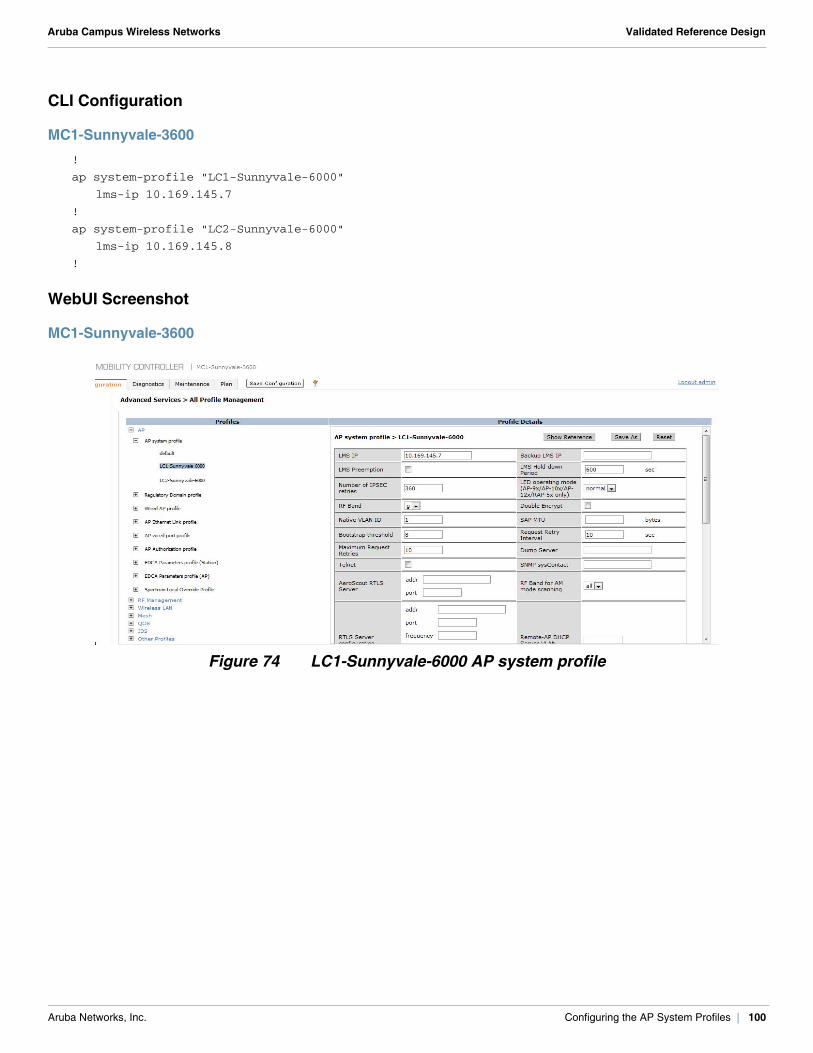
Aruba Campus Wireless Networks Validated Reference Design
CLI Configuration
MC1-Sunnyvale-3600!
ap system-profile "LC1-Sunnyvale-6000"
lms-ip 10.169.145.7
!
ap system-profile "LC2-Sunnyvale-6000"
lms-ip 10.169.145.8
!
WebUI Screenshot
MC1-Sunnyvale-3600
Figure 74 LC1-Sunnyvale-6000 AP system profile
Aruba Networks, Inc. Configuring the AP System Profiles | 100
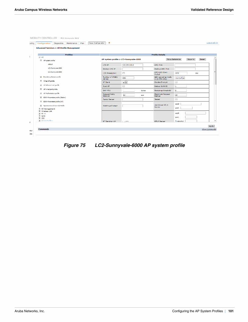
Aruba Campus Wireless Networks Validated Reference Design
Figure 75 LC2-Sunnyvale-6000 AP system profile
Aruba Networks, Inc. Configuring the AP System Profiles | 101

Aruba Campus Wireless Networks Validated Reference Design
Aruba Networks, Inc. Configuring the AP System Profiles | 102
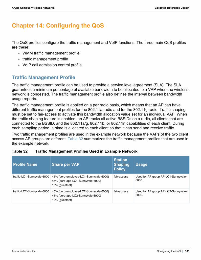
Aruba Campus Wireless Networks Validated Reference Design
Chapter 14: Configuring the QoS
The QoS profiles configure the traffic management and VoIP functions. The three main QoS profiles are these:
WMM traffic management profile traffic management profile VoIP call admission control profile
Traffic Management ProfileThe traffic management profile can be used to provide a service level agreement (SLA). The SLA guarantees a minimum percentage of available bandwidth to be allocated to a VAP when the wireless network is congested. The traffic management profile also defines the interval between bandwidth usage reports.
The traffic management profile is applied on a per radio basis, which means that an AP can have different traffic management profiles for the 802.11a radio and for the 802.11g radio. Traffic shaping must be set to fair-access to activate this bandwidth allocation value set for an individual VAP. When the traffic shaping feature is enabled, an AP tracks all active BSSIDs on a radio, all clients that are connected to the BSSID, and the 802.11a/g, 802.11b, or 802.11n capabilities of each client. During each sampling period, airtime is allocated to each client so that it can send and receive traffic.
Two traffic management profiles are used in the example network because the VAPs of the two client access AP groups are different. Table 32 summarizes the traffic management profiles that are used in the example network.
Table 32 Traffic Management Profiles Used in Example Network
Profile Name Share per VAPStation Shaping Policy
Usage
traffic-LC1-Sunnyvale-6000 45% (corp-employee-LC1-Sunnyvale-6000)45% (corp-app-LC1-Sunnyvale-6000)10% (guestnet)
fair-access Used for AP group AP-LC1-Sunnyvale-6000.
traffic-LC2-Sunnyvale-6000 45% (corp-employee-LC2-Sunnyvale-6000)45% (corp-app-LC2-Sunnyvale-6000) 10% (guestnet)
fair-access Used for AP group AP-LC2-Sunnyvale-6000.
Aruba Networks, Inc. Configuring the QoS | 103
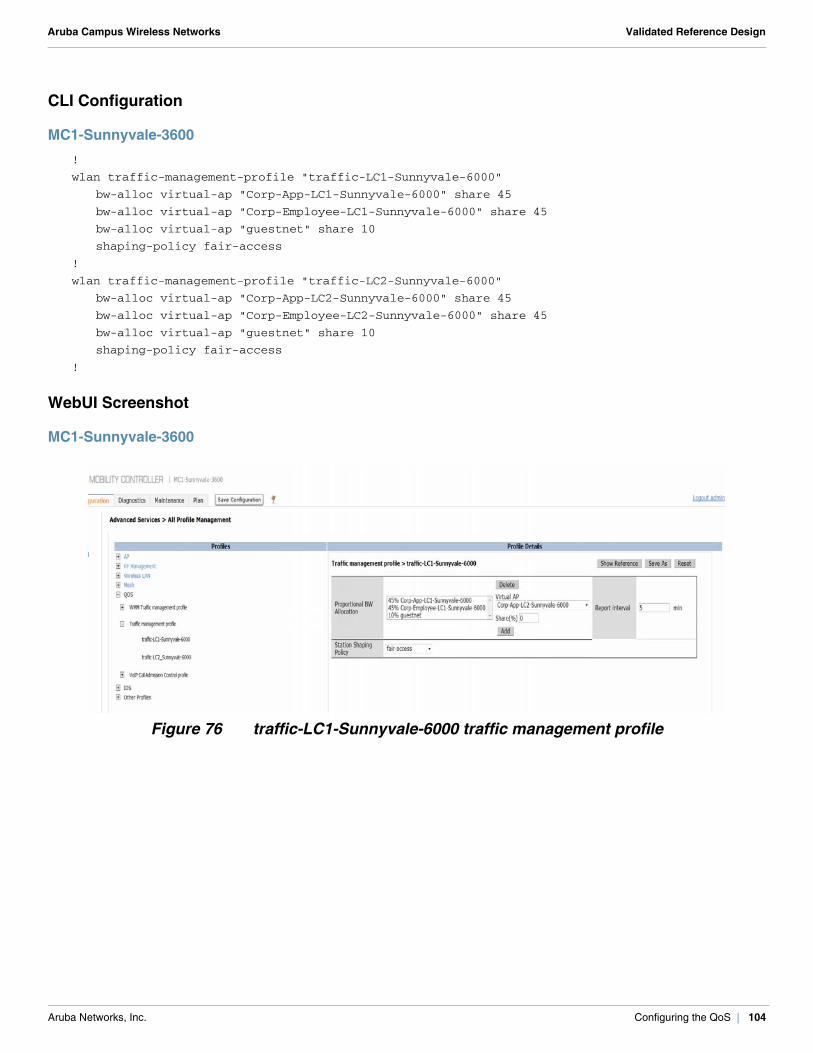
Aruba Campus Wireless Networks Validated Reference Design
CLI Configuration
MC1-Sunnyvale-3600!
wlan traffic-management-profile "traffic-LC1-Sunnyvale-6000"
bw-alloc virtual-ap "Corp-App-LC1-Sunnyvale-6000" share 45
bw-alloc virtual-ap "Corp-Employee-LC1-Sunnyvale-6000" share 45
bw-alloc virtual-ap "guestnet" share 10
shaping-policy fair-access
!
wlan traffic-management-profile "traffic-LC2-Sunnyvale-6000"
bw-alloc virtual-ap "Corp-App-LC2-Sunnyvale-6000" share 45
bw-alloc virtual-ap "Corp-Employee-LC2-Sunnyvale-6000" share 45
bw-alloc virtual-ap "guestnet" share 10
shaping-policy fair-access
!
WebUI Screenshot
MC1-Sunnyvale-3600
Figure 76 traffic-LC1-Sunnyvale-6000 traffic management profile
Aruba Networks, Inc. Configuring the QoS | 104
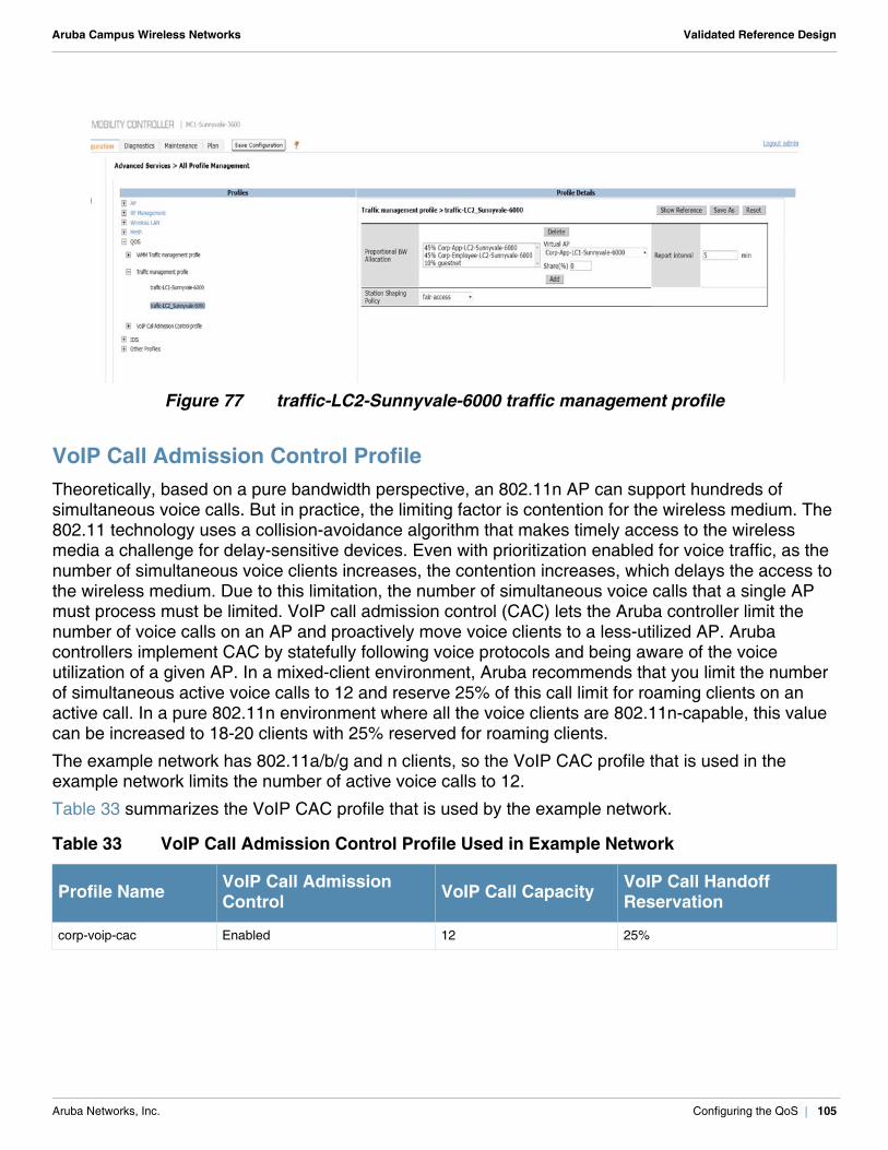
Aruba Campus Wireless Networks Validated Reference Design
Figure 77 traffic-LC2-Sunnyvale-6000 traffic management profile
VoIP Call Admission Control ProfileTheoretically, based on a pure bandwidth perspective, an 802.11n AP can support hundreds of simultaneous voice calls. But in practice, the limiting factor is contention for the wireless medium. The 802.11 technology uses a collision-avoidance algorithm that makes timely access to the wireless media a challenge for delay-sensitive devices. Even with prioritization enabled for voice traffic, as the number of simultaneous voice clients increases, the contention increases, which delays the access to the wireless medium. Due to this limitation, the number of simultaneous voice calls that a single AP must process must be limited. VoIP call admission control (CAC) lets the Aruba controller limit the number of voice calls on an AP and proactively move voice clients to a less-utilized AP. Aruba controllers implement CAC by statefully following voice protocols and being aware of the voice utilization of a given AP. In a mixed-client environment, Aruba recommends that you limit the number of simultaneous active voice calls to 12 and reserve 25% of this call limit for roaming clients on an active call. In a pure 802.11n environment where all the voice clients are 802.11n-capable, this value can be increased to 18-20 clients with 25% reserved for roaming clients.
The example network has 802.11a/b/g and n clients, so the VoIP CAC profile that is used in the example network limits the number of active voice calls to 12.
Table 33 summarizes the VoIP CAC profile that is used by the example network.
Table 33 VoIP Call Admission Control Profile Used in Example Network
Profile Name VoIP Call Admission Control VoIP Call Capacity VoIP Call Handoff
Reservation
corp-voip-cac Enabled 12 25%
Aruba Networks, Inc. Configuring the QoS | 105
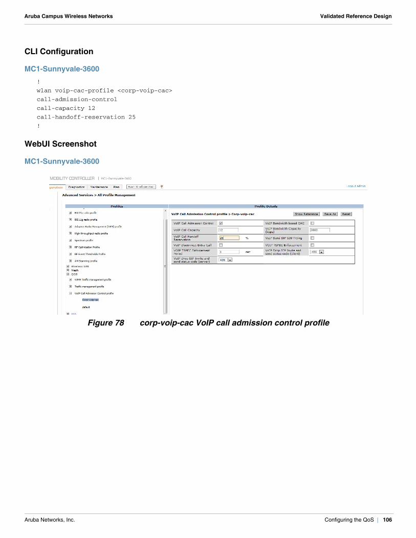
Aruba Campus Wireless Networks Validated Reference Design
CLI Configuration
MC1-Sunnyvale-3600!
wlan voip-cac-profile <corp-voip-cac>
call-admission-control
call-capacity 12
call-handoff-reservation 25
!
WebUI Screenshot
MC1-Sunnyvale-3600
Figure 78 corp-voip-cac VoIP call admission control profile
Aruba Networks, Inc. Configuring the QoS | 106

Aruba Campus Wireless Networks Validated Reference Design
Chapter 15: Configuring the Client Access AP Groups
An AP group is a unique collection of configuration profiles. After you have configured all the required profiles, it is easy to form an AP group. To form an AP group, simply mix-and-match profiles based on the requirements.
The AP-LC1-Sunnyvale-6000 AP group is used for all APs that must be managed by the LC1-Sunnyvale-6000 local controller. The AP-LC2-Sunnyvale-6000 AP group is used for all APs that must be managed by the LC2-Sunnyvale-6000 local controller.
Table 34 summarizes the two AP groups that are used to provide client access in the example network and the profiles associated with each of these AP groups.
Table 34 AP-LC1-Sunnyvale-6000 and AP-LC2-Sunnyvale-6000 AP Groups
Profile Categories Profile Type AP-LC1-Sunnyvale-6000
Profiles UsedAP-LC2-Sunnyvale-6000Profiles Used
Wireless LAN VAP profile corp-employee-LC1-Sunnyvale-6000
corp-app-LC1-Sunnyvale-6000
guestnet
corp-employee-LC2-Sunnyvale-6000
corp-app-LC2-Sunnyvale-6000
guestnet
RF Management 802.11a radio profile AP AP
802.11g radio profile AP AP
AP AP system profile LC1-Sunnyvale-6000 LC2-Sunnyvale-6000
QoS 802.11a traffic management profile
traffic-LC1-Sunnyvale-6000 traffic-LC2-Sunnyvale-6000
802.11g traffic management profile
traffic-LC1-Sunnyvale-6000 traffic-LC2-Sunnyvale-6000
VoIP call admission control profile
corp-voip-cac corp-voip-cac
IDS IDS profile (use the wizard) Corp-WIPS (Created using the wizard, see Chapter 18: Wireless Intrusion Prevention (IDS Profiles) of RFProtect on page 119.)
Corp-WIPS (Created using the wizard, see Chapter 18: Wireless Intrusion Prevention (IDS Profiles) of RFProtect on page 119.)
Aruba Networks, Inc. Configuring the Client Access AP Groups | 107
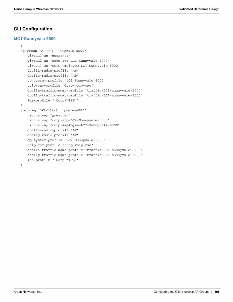
Aruba Campus Wireless Networks Validated Reference Design
CLI Configuration
MC1-Sunnyvale-3600!
ap-group "AP-LC1-Sunnyvale-6000"
virtual-ap "guestnet"
virtual-ap "corp-app-LC1-Sunnyvale-6000"
virtual-ap "corp-employee-LC1-Sunnyvale-6000"
dot11a-radio-profile "AP"
dot11g-radio-profile "AP"
ap-system-profile "LC1-Sunnyvale-6000"
voip-cac-profile "Corp-voip-cac"
dot11a-traffic-mgmt-profile "traffic-LC1-sunnyvale-6000"
dot11g-traffic-mgmt-profile "traffic-LC1-sunnyvale-6000"
ids-profile " Corp-WIPS "
!
ap-group "AP-LC2-Sunnyvale-6000"
virtual-ap "guestnet"
virtual-ap "corp-app-LC2-Sunnyvale-6000"
virtual-ap "corp-employee-LC2-Sunnyvale-6000"
dot11a-radio-profile "AP"
dot11g-radio-profile "AP"
ap-system-profile "LC2-Sunnyvale-6000"
voip-cac-profile "corp-voip-cac"
dot11a-traffic-mgmt-profile "traffic-LC2-sunnyvale-6000"
dot11g-traffic-mgmt-profile "traffic-LC2-sunnyvale-6000"
ids-profile " Corp-WIPS "
!
Aruba Networks, Inc. Configuring the Client Access AP Groups | 108
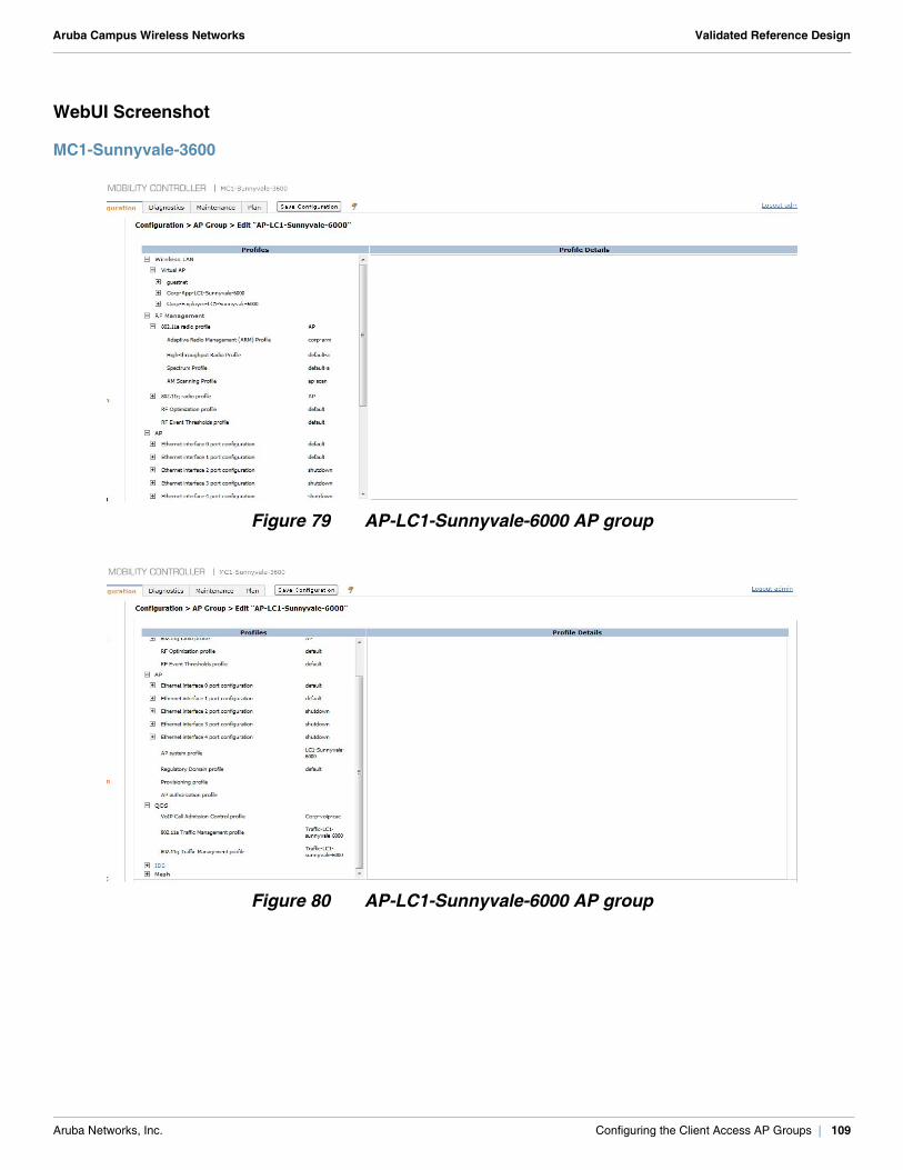
Aruba Campus Wireless Networks Validated Reference Design
WebUI Screenshot
MC1-Sunnyvale-3600
Figure 79 AP-LC1-Sunnyvale-6000 AP group
Figure 80 AP-LC1-Sunnyvale-6000 AP group
Aruba Networks, Inc. Configuring the Client Access AP Groups | 109

Aruba Campus Wireless Networks Validated Reference Design
Aruba Networks, Inc. Configuring the Client Access AP Groups | 110
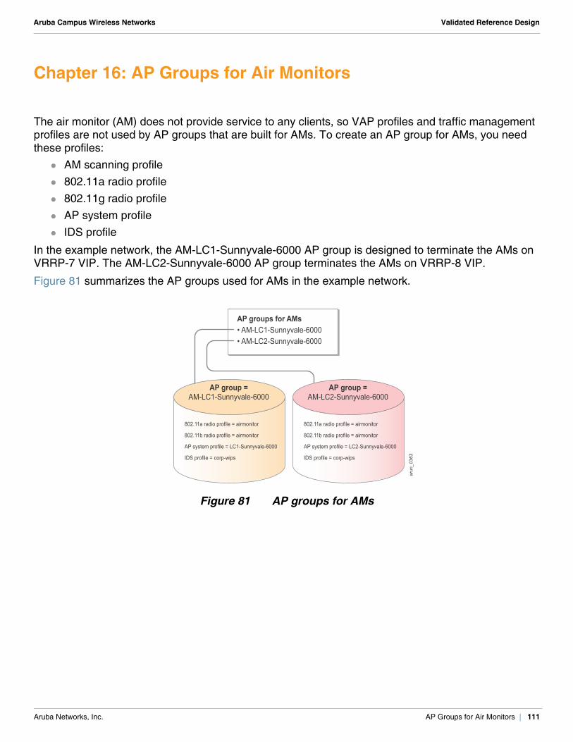
Aruba Campus Wireless Networks Validated Reference Design
Chapter 16: AP Groups for Air Monitors
The air monitor (AM) does not provide service to any clients, so VAP profiles and traffic management profiles are not used by AP groups that are built for AMs. To create an AP group for AMs, you need these profiles:
AM scanning profile 802.11a radio profile 802.11g radio profile AP system profile IDS profile
In the example network, the AM-LC1-Sunnyvale-6000 AP group is designed to terminate the AMs on VRRP-7 VIP. The AM-LC2-Sunnyvale-6000 AP group terminates the AMs on VRRP-8 VIP.
Figure 81 summarizes the AP groups used for AMs in the example network.
Figure 81 AP groups for AMs
802.11a radio profile = airmonitor
802.11b radio profile = airmonitor
AP system profile = LC1-Sunnyvale-6000
IDS profile = corp-wips
802.11a radio profile = airmonitor
802.11b radio profile = airmonitor
AP system profile = LC2-Sunnyvale-6000
IDS profile = corp-wips
arun_0363
AP groups for AMs• AM-LC1-Sunnyvale-6000• AM-LC2-Sunnyvale-6000
AP group =AM-LC1-Sunnyvale-6000
AP group =AM-LC2-Sunnyvale-6000
Aruba Networks, Inc. AP Groups for Air Monitors | 111
Aruba Campus Wireless Networks Validated Reference Design
Configuring the AM Scanning ProfileThe RFProtect feature set that was introduced in ArubaOS 6.0 provides the TotalWatchTM scanning tool. When you add the RFProtect license, TotalWatch is enabled by default. TotalWatch extends the scanning capabilities of an AM to all the 14 channels in the 2.4 GHz and to the entire 4.9 – 5.895 GHz spectrum in 5 MHz increments.
For more information about TotalWatch, see the Aruba Mobility Controllers and Deployment Models Validated Reference Design.
The AM scanning profile defines all the settings that are related to TotalWatch. The scanning profile applies only to radios operating as dedicated AMs and determines their scanning capabilities. The scanning capabilities of a radio operating as an AP are determined by the scan-mode parameter in the ARM profile. Aruba does not recommend that you change the following four parameters of this profile under any circumstances, unless specifically advised by the Aruba Technical Assistance Center (TAC) team:
Dwell time: active channels Dwell time: regulatory domain channels Dwell time: non-regulatory domain channels Dwell time: rare channels
The scan-mode parameter in this profile determines the range of channels that are scanned by an AM. Aruba recommends that you set this value to rare for all AMs. If you set this value to rare on AMs, the AMs scan the 4.9 GHz range and the entire 2.4 GHz and 5 GHz range.
!CAUTION
Only rogues on legal channels are contained wirelessly, but rogues on any channel can be contained using wired containment. All rogues that are detected wirelessly are reported, but wireless containment can be taken only against rogues that operate within the regulatory domain. APs and AMs cannot transmit, even to contain rogues, outside of the legal regulatory domain channels they are operating in without violating local law. The 4.9 GHz range is reserved for public safety applications in most regulatory domains. The open source hardware drivers and software-defined radios in many consumer grade APs mean that a malicious user could program an AP to operate illegally in this range. Aruba AMs scan this range and report back any rogue AP found operating on this band. However, due to regulatory restrictions, the AM cannot contain the device.
Aruba Networks, Inc. AP Groups for Air Monitors | 112
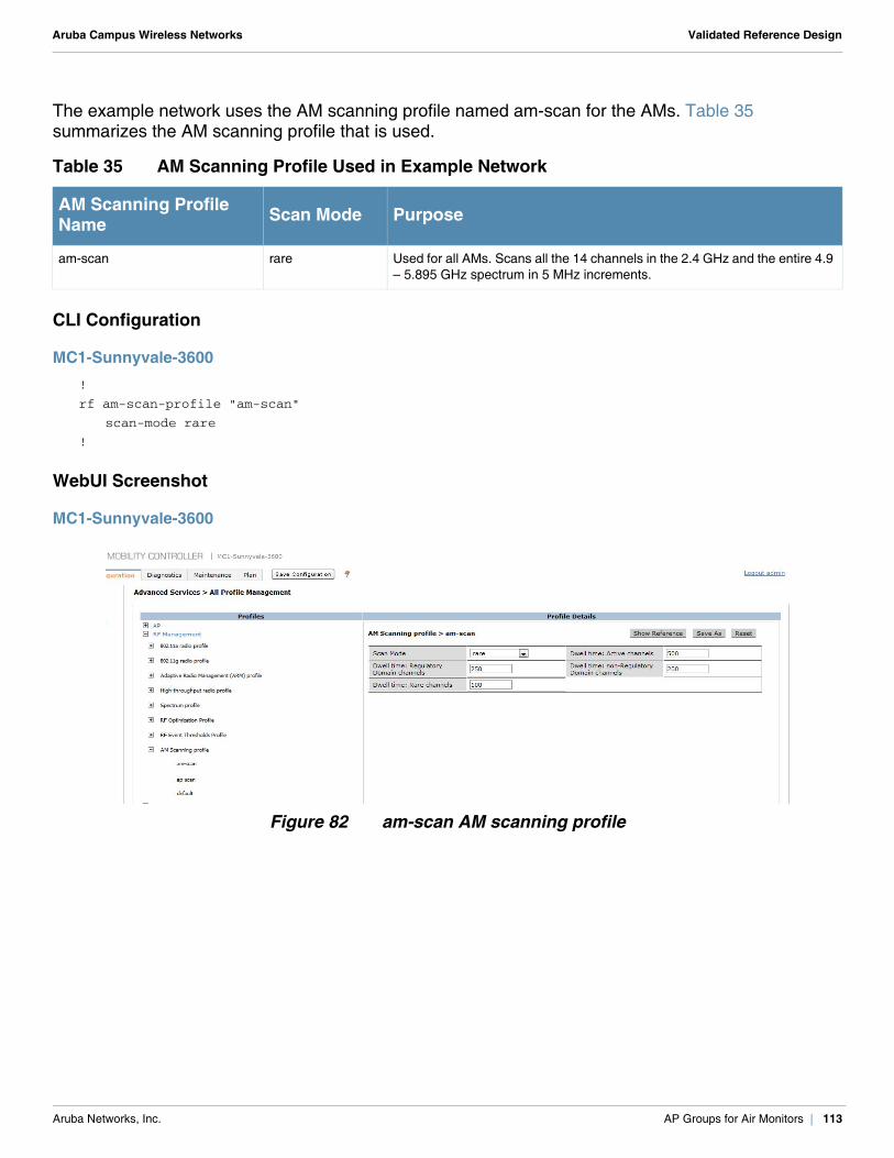
Aruba Campus Wireless Networks Validated Reference Design
The example network uses the AM scanning profile named am-scan for the AMs. Table 35 summarizes the AM scanning profile that is used.
CLI Configuration
MC1-Sunnyvale-3600!
rf am-scan-profile "am-scan"
scan-mode rare
!
WebUI Screenshot
MC1-Sunnyvale-3600
Figure 82 am-scan AM scanning profile
Table 35 AM Scanning Profile Used in Example Network
AM Scanning Profile Name Scan Mode Purpose
am-scan rare Used for all AMs. Scans all the 14 channels in the 2.4 GHz and the entire 4.9 – 5.895 GHz spectrum in 5 MHz increments.
Aruba Networks, Inc. AP Groups for Air Monitors | 113
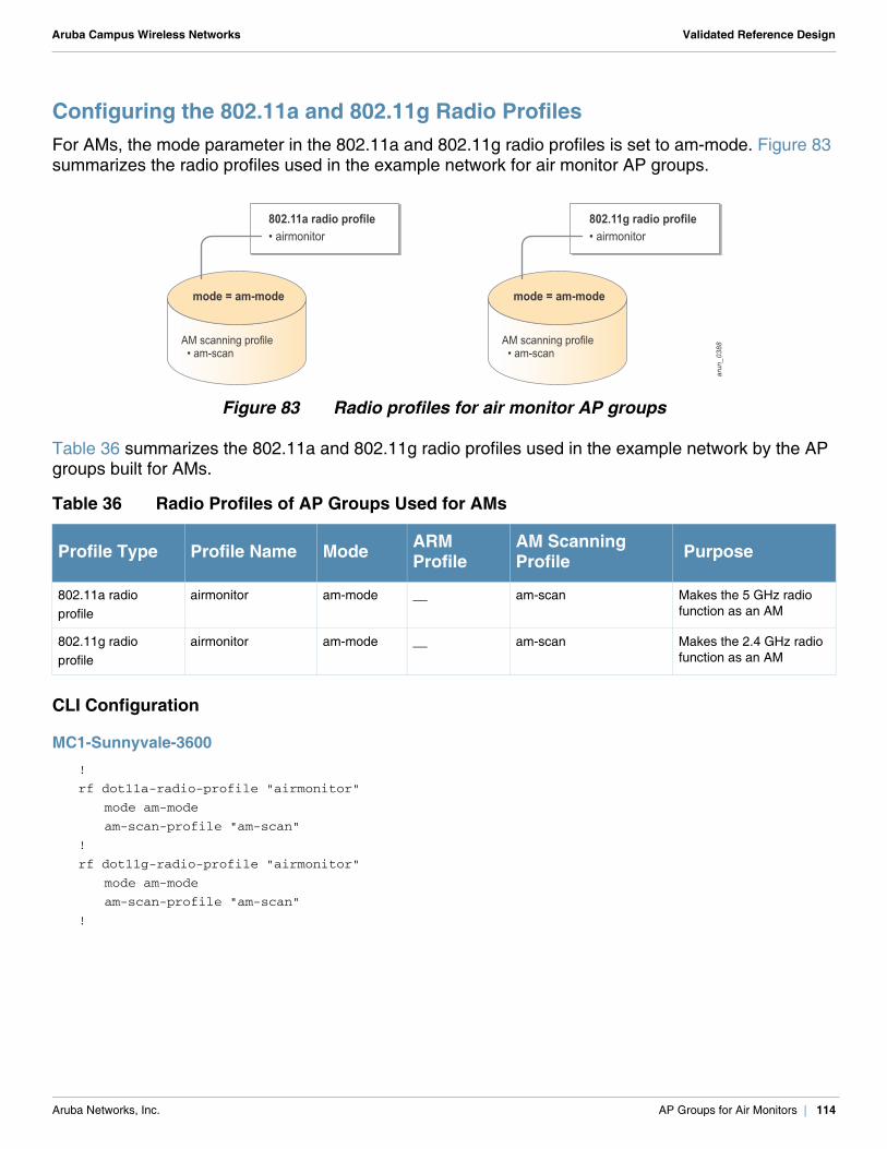
Aruba Campus Wireless Networks Validated Reference Design
Configuring the 802.11a and 802.11g Radio Profiles For AMs, the mode parameter in the 802.11a and 802.11g radio profiles is set to am-mode. Figure 83 summarizes the radio profiles used in the example network for air monitor AP groups.
Figure 83 Radio profiles for air monitor AP groups
Table 36 summarizes the 802.11a and 802.11g radio profiles used in the example network by the AP groups built for AMs.
CLI Configuration
MC1-Sunnyvale-3600!
rf dot11a-radio-profile "airmonitor"
mode am-mode
am-scan-profile "am-scan"
!
rf dot11g-radio-profile "airmonitor"
mode am-mode
am-scan-profile "am-scan"
!
Table 36 Radio Profiles of AP Groups Used for AMs
Profile Type Profile Name Mode ARM Profile
AM Scanning Profile Purpose
802.11a radioprofile
airmonitor am-mode __ am-scan Makes the 5 GHz radio function as an AM
802.11g radioprofile
airmonitor am-mode __ am-scan Makes the 2.4 GHz radio function as an AM
802.11a radio profile• airmonitor
802.11g radio profile• airmonitor
arun_0388
mode = am-mode mode = am-mode
AM scanning profile • am-scan
AM scanning profile • am-scan
Aruba Networks, Inc. AP Groups for Air Monitors | 114
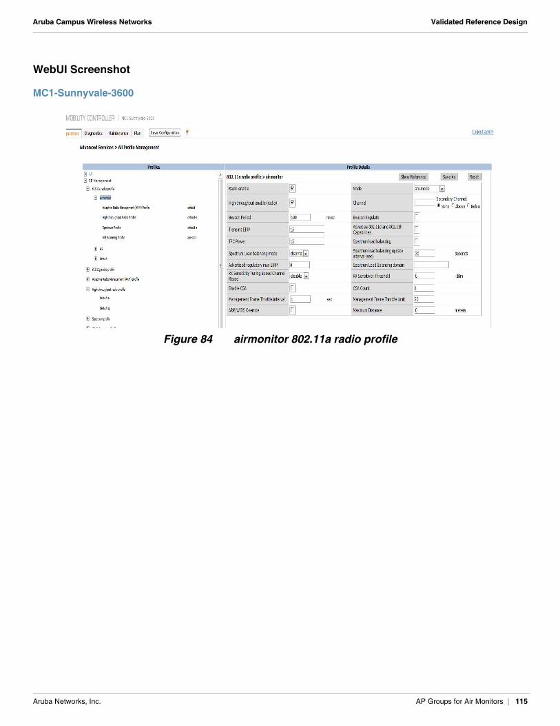
Aruba Campus Wireless Networks Validated Reference Design
WebUI Screenshot
MC1-Sunnyvale-3600
Figure 84 airmonitor 802.11a radio profile
Aruba Networks, Inc. AP Groups for Air Monitors | 115
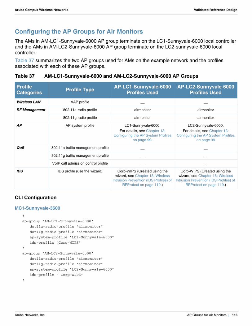
Aruba Campus Wireless Networks Validated Reference Design
Configuring the AP Groups for Air MonitorsThe AMs in AM-LC1-Sunnyvale-6000 AP group terminate on the LC1-Sunnyvale-6000 local controller and the AMs in AM-LC2-Sunnyvale-6000 AP group terminate on the LC2-sunnyvale-6000 local controller.
Table 37 summarizes the two AP groups used for AMs on the example network and the profiles associated with each of these AP groups.
CLI Configuration
MC1-Sunnyvale-3600!
ap-group "AM-LC1-Sunnyvale-6000"
dot11a-radio-profile "airmonitor"
dot11g-radio-profile "airmonitor"
ap-system-profile "LC1-Sunnyvale-6000"
ids-profile "Corp-WIPS"
!
ap-group "AM-LC2-Sunnyvale-6000"
dot11a-radio-profile "airmonitor"
dot11g-radio-profile "airmonitor"
ap-system-profile "LC2-Sunnyvale-6000"
ids-profile " Corp-WIPS"
!
Table 37 AM-LC1-Sunnyvale-6000 and AM-LC2-Sunnyvale-6000 AP Groups
Profile Categories Profile Type AP-LC1-Sunnyvale-6000
Profiles UsedAP-LC2-Sunnyvale-6000
Profiles Used
Wireless LAN VAP profile __ __
RF Management 802.11a radio profile airmonitor airmonitor
802.11g radio profile airmonitor airmonitor
AP AP system profile LC1-Sunnyvale-6000. For details, see Chapter 13:
Configuring the AP System Profiles on page 99.
LC2-Sunnyvale-6000. For details, see Chapter 13:
Configuring the AP System Profiles on page 99
QoS 802.11a traffic management profile __ __
802.11g traffic management profile __ __
VoIP call admission control profile __ __
IDS IDS profile (use the wizard) Corp-WIPS (Created using the wizard, see Chapter 18: Wireless
Intrusion Prevention (IDS Profiles) of RFProtect on page 119.)
Corp-WIPS (Created using the wizard, see Chapter 18: Wireless
Intrusion Prevention (IDS Profiles) of RFProtect on page 119.)
Aruba Networks, Inc. AP Groups for Air Monitors | 116
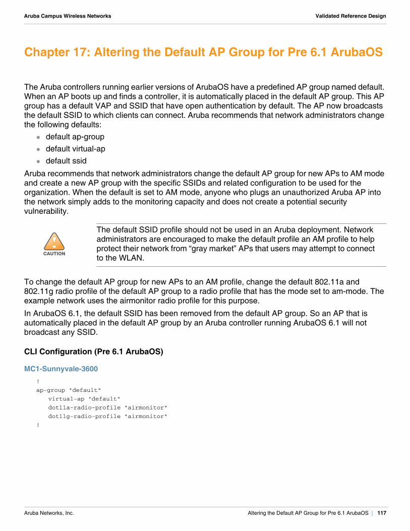
Aruba Campus Wireless Networks Validated Reference Design
Chapter 17: Altering the Default AP Group for Pre 6.1 ArubaOS
The Aruba controllers running earlier versions of ArubaOS have a predefined AP group named default. When an AP boots up and finds a controller, it is automatically placed in the default AP group. This AP group has a default VAP and SSID that have open authentication by default. The AP now broadcasts the default SSID to which clients can connect. Aruba recommends that network administrators change the following defaults:
default ap-group default virtual-ap default ssid
Aruba recommends that network administrators change the default AP group for new APs to AM mode and create a new AP group with the specific SSIDs and related configuration to be used for the organization. When the default is set to AM mode, anyone who plugs an unauthorized Aruba AP into the network simply adds to the monitoring capacity and does not create a potential security vulnerability.
To change the default AP group for new APs to an AM profile, change the default 802.11a and 802.11g radio profile of the default AP group to a radio profile that has the mode set to am-mode. The example network uses the airmonitor radio profile for this purpose.
In ArubaOS 6.1, the default SSID has been removed from the default AP group. So an AP that is automatically placed in the default AP group by an Aruba controller running ArubaOS 6.1 will not broadcast any SSID.
CLI Configuration (Pre 6.1 ArubaOS)
MC1-Sunnyvale-3600!
ap-group "default"
virtual-ap "default"
dot11a-radio-profile "airmonitor"
dot11g-radio-profile "airmonitor"
!
!CAUTION
The default SSID profile should not be used in an Aruba deployment. Network administrators are encouraged to make the default profile an AM profile to help protect their network from “gray market” APs that users may attempt to connect to the WLAN.
Aruba Networks, Inc. Altering the Default AP Group for Pre 6.1 ArubaOS | 117
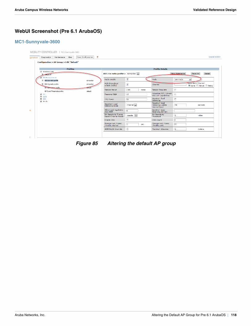
Aruba Campus Wireless Networks Validated Reference Design
WebUI Screenshot (Pre 6.1 ArubaOS)
MC1-Sunnyvale-3600
Figure 85 Altering the default AP group
Aruba Networks, Inc. Altering the Default AP Group for Pre 6.1 ArubaOS | 118
Aruba Campus Wireless Networks Validated Reference Design
Chapter 18: Wireless Intrusion Prevention (IDS Profiles) of RFProtect
In any wireless network, it is important to protect the network against wireless attacks. Wireless security must be used in many regulated industries such as:
healthcare federal payment card industry
The ArubaOS wireless intrusion prevention (WIP) feature of the RFProtect software module provides a wide range of intrusion detection and intrusion prevention capabilities.
The RFProtect feature set of ArubaOS 6.1 also includes a patented containment called tarpitting. For more details on tarpitting and other RFProtect features, see the Aruba 802.11n Networks Validated Reference Design. The intrusion detection system (IDS) profiles define all the possible WIP settings. Wireless security can be a complex topic with many different options, and it can be difficult to manage the wide range of IDS profiles available. To make things easier for users, Aruba developed a set of powerful wizards. Aruba wizards provide reasonable default values and help a user step through the available configuration options. You select a default template that provides an acceptable level of security for the network or a customized set of options. The wizard simplifies the selection of security options and helps to eliminate errors in the configuration. Aruba recommends the use of the WIP wizard for WIP configuration.
The WIP wizard provides the options to enable, define, or change the following items: rule-based rogue classification WIP policy creation and assignment to AP groups detection options for infrastructure attacks detection options for WLAN clients attacks protection options for infrastructure attacks protection options for WLAN clients attacks
Aruba Networks, Inc. Wireless Intrusion Prevention (IDS Profiles) of RFProtect | 119
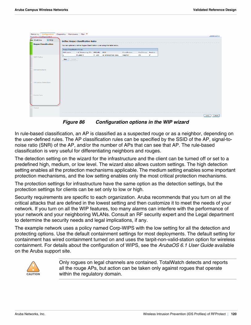
Aruba Campus Wireless Networks Validated Reference Design
Figure 86 Configuration options in the WIP wizard
In rule-based classification, an AP is classified as a suspected rouge or as a neighbor, depending on the user-defined rules. The AP classification rules can be specified by the SSID of the AP, signal-to-noise ratio (SNR) of the AP, and/or the number of APs that can see that AP. The rule-based classification is very useful for differentiating neighbors and rouges.
The detection setting on the wizard for the infrastructure and the client can be turned off or set to a predefined high, medium, or low level. The wizard also allows custom settings. The high detection setting enables all the protection mechanisms applicable. The medium setting enables some important protection mechanisms, and the low setting enables only the most critical protection mechanisms.
The protection settings for infrastructure have the same option as the detection settings, but the protection settings for clients can be set only to low or high.
Security requirements are specific to each organization. Aruba recommends that you turn on all the critical attacks that are defined in the lowest setting and then customize it to meet the needs of your network. If you turn on all the WIP features, too many alarms can interfere with the performance of your network and your neighboring WLANs. Consult an RF security expert and the Legal department to determine the security needs and legal implications, if any.
The example network uses a policy named Corp-WIPS with the low setting for all the detection and protecting options. Use the default containment settings for most deployments. The default setting for containment has wired containment turned on and uses the tarpit-non-valid-station option for wireless containment. For details about the configuration of WIPS, see the ArubaOS 6.1 User Guide available on the Aruba support site.
!CAUTION
Only rogues on legal channels are contained. TotalWatch detects and reports all the rouge APs, but action can be taken only against rogues that operate within the regulatory domain.
Aruba Networks, Inc. Wireless Intrusion Prevention (IDS Profiles) of RFProtect | 120
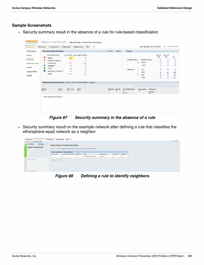
Aruba Campus Wireless Networks Validated Reference Design
Sample Screenshots
Security summary result in the absence of a rule for rule-based classification
Figure 87 Security summary in the absence of a rule
Security summary result on the example network after defining a rule that classifies the ethersphere-wpa2 network as a neighbor
Figure 88 Defining a rule to identify neighbors
Aruba Networks, Inc. Wireless Intrusion Prevention (IDS Profiles) of RFProtect | 121
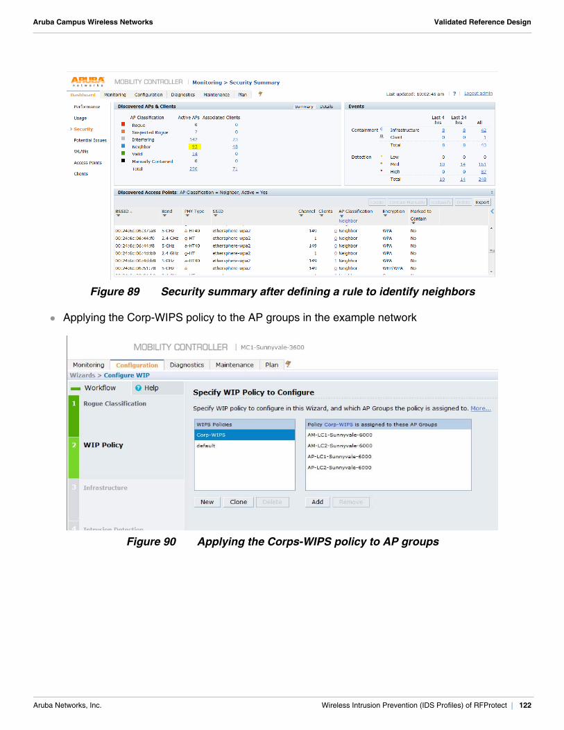
Aruba Campus Wireless Networks Validated Reference Design
Figure 89 Security summary after defining a rule to identify neighbors
Applying the Corp-WIPS policy to the AP groups in the example network
Figure 90 Applying the Corps-WIPS policy to AP groups
Aruba Networks, Inc. Wireless Intrusion Prevention (IDS Profiles) of RFProtect | 122
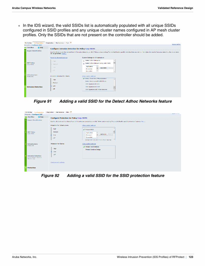
Aruba Campus Wireless Networks Validated Reference Design
In the IDS wizard, the valid SSIDs list is automatically populated with all unique SSIDs configured in SSID profiles and any unique cluster names configured in AP mesh cluster profiles. Only the SSIDs that are not present on the controller should be added.
Figure 91 Adding a valid SSID for the Detect Adhoc Networks feature
Figure 92 Adding a valid SSID for the SSID protection feature
Aruba Networks, Inc. Wireless Intrusion Prevention (IDS Profiles) of RFProtect | 123

Aruba Campus Wireless Networks Validated Reference Design
Aruba Networks, Inc. Wireless Intrusion Prevention (IDS Profiles) of RFProtect | 124
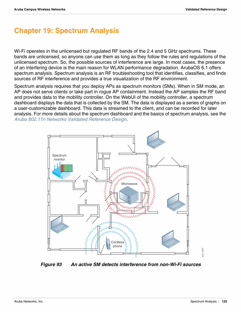
Aruba Campus Wireless Networks Validated Reference Design
Chapter 19: Spectrum Analysis
Wi-Fi operates in the unlicensed but regulated RF bands of the 2.4 and 5 GHz spectrums. These bands are unlicensed, so anyone can use them as long as they follow the rules and regulations of the unlicensed spectrum. So, the possible sources of interference are large. In most cases, the presence of an interfering device is the main reason for WLAN performance degradation. ArubaOS 6.1 offers spectrum analysis. Spectrum analysis is an RF troubleshooting tool that identifies, classifies, and finds sources of RF interference and provides a true visualization of the RF environment.
Spectrum analysis requires that you deploy APs as spectrum monitors (SMs). When in SM mode, an AP does not serve clients or take part in rogue AP containment. Instead the AP samples the RF band and provides data to the mobility controller. On the WebUI of the mobility controller, a spectrum dashboard displays the data that is collected by the SM. The data is displayed as a series of graphs on a user-customizable dashboard. This data is streamed to the client, and can be recorded for later analysis. For more details about the spectrum dashboard and the basics of spectrum analysis, see the Aruba 802.11n Networks Validated Reference Design.
Figure 93 An active SM detects interference from non-Wi-Fi sources
Microwave
Cordlessphone
arun_0307
Spectrummonitor
Aruba Networks, Inc. Spectrum Analysis | 125
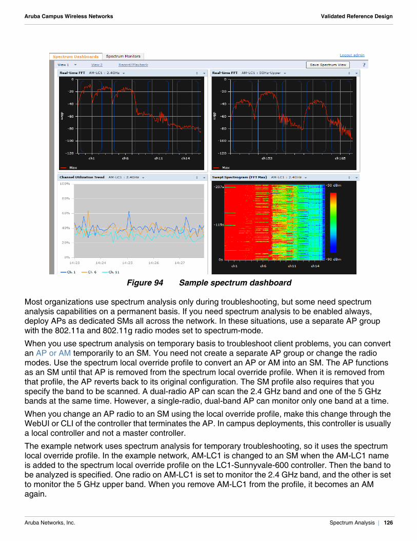
Aruba Campus Wireless Networks Validated Reference Design
Figure 94 Sample spectrum dashboard
Most organizations use spectrum analysis only during troubleshooting, but some need spectrum analysis capabilities on a permanent basis. If you need spectrum analysis to be enabled always, deploy APs as dedicated SMs all across the network. In these situations, use a separate AP group with the 802.11a and 802.11g radio modes set to spectrum-mode.
When you use spectrum analysis on temporary basis to troubleshoot client problems, you can convert an AP or AM temporarily to an SM. You need not create a separate AP group or change the radio modes. Use the spectrum local override profile to convert an AP or AM into an SM. The AP functions as an SM until that AP is removed from the spectrum local override profile. When it is removed from that profile, the AP reverts back to its original configuration. The SM profile also requires that you specify the band to be scanned. A dual-radio AP can scan the 2.4 GHz band and one of the 5 GHz bands at the same time. However, a single-radio, dual-band AP can monitor only one band at a time.
When you change an AP radio to an SM using the local override profile, make this change through the WebUI or CLI of the controller that terminates the AP. In campus deployments, this controller is usually a local controller and not a master controller.
The example network uses spectrum analysis for temporary troubleshooting, so it uses the spectrum local override profile. In the example network, AM-LC1 is changed to an SM when the AM-LC1 name is added to the spectrum local override profile on the LC1-Sunnyvale-600 controller. Then the band to be analyzed is specified. One radio on AM-LC1 is set to monitor the 2.4 GHz band, and the other is set to monitor the 5 GHz upper band. When you remove AM-LC1 from the profile, it becomes an AM again.
Aruba Networks, Inc. Spectrum Analysis | 126
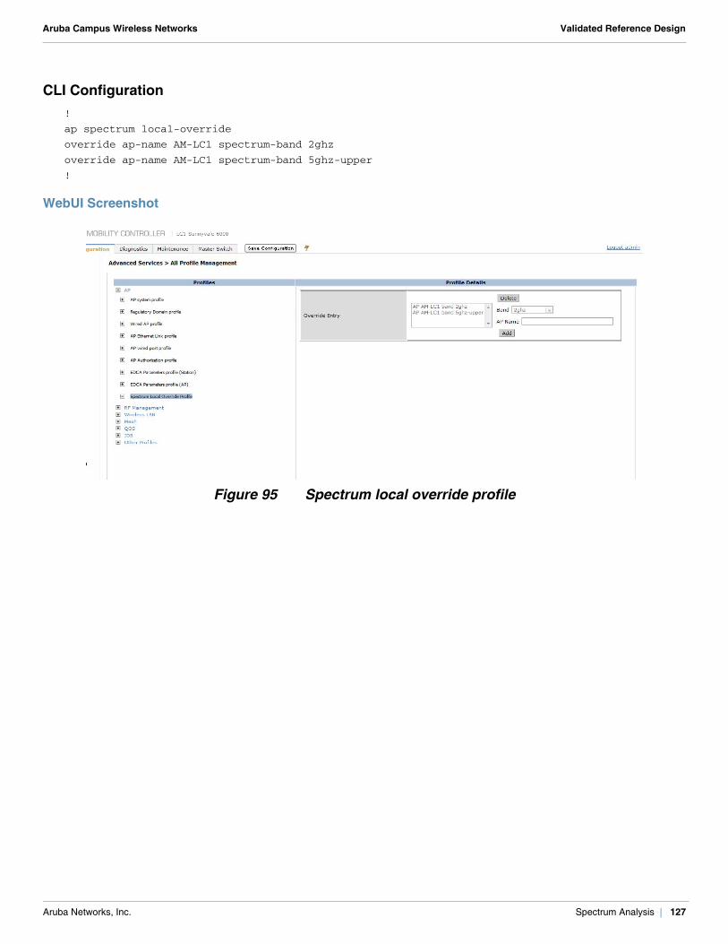
Aruba Campus Wireless Networks Validated Reference Design
CLI Configuration!
ap spectrum local-override
override ap-name AM-LC1 spectrum-band 2ghz
override ap-name AM-LC1 spectrum-band 5ghz-upper
!
WebUI Screenshot
Figure 95 Spectrum local override profile
Aruba Networks, Inc. Spectrum Analysis | 127

Aruba Campus Wireless Networks Validated Reference Design
Aruba Networks, Inc. Spectrum Analysis | 128
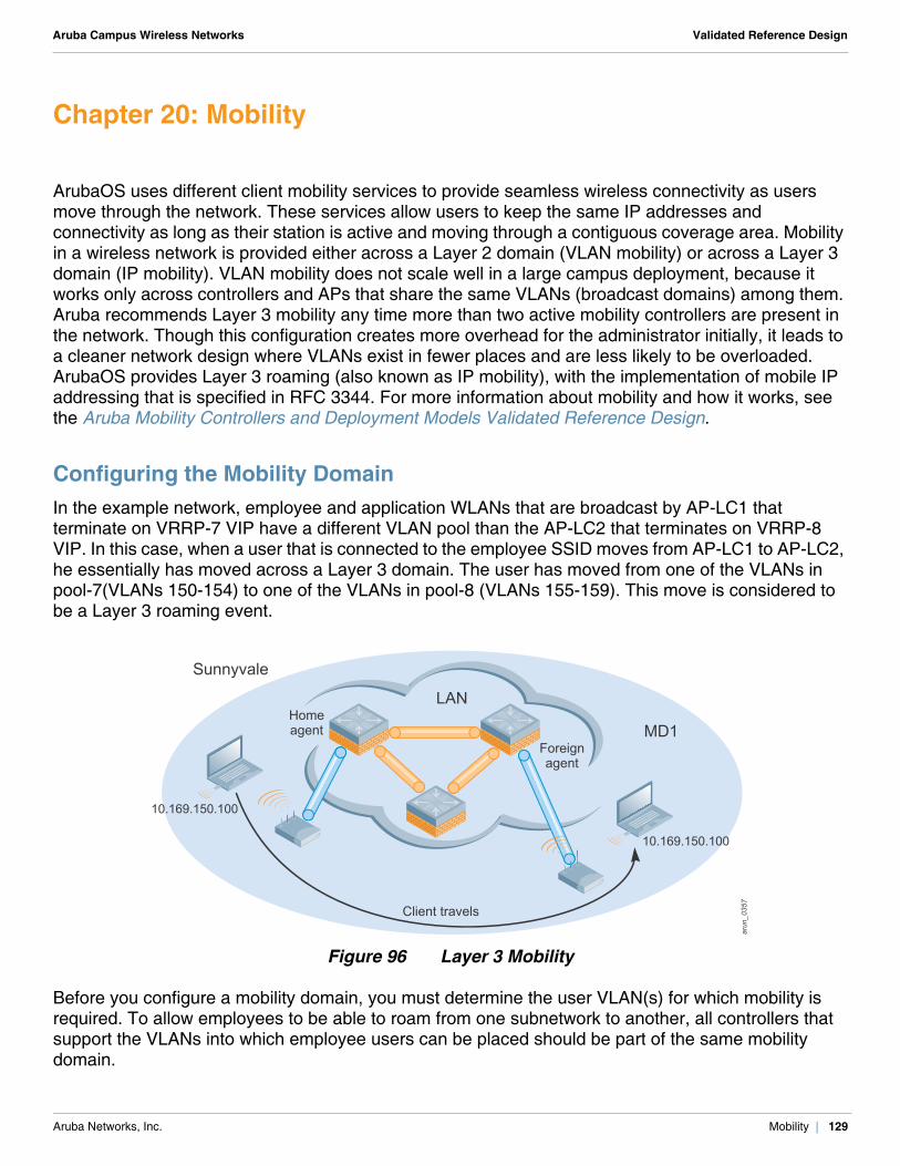
Aruba Campus Wireless Networks Validated Reference Design
Chapter 20: Mobility
ArubaOS uses different client mobility services to provide seamless wireless connectivity as users move through the network. These services allow users to keep the same IP addresses and connectivity as long as their station is active and moving through a contiguous coverage area. Mobility in a wireless network is provided either across a Layer 2 domain (VLAN mobility) or across a Layer 3 domain (IP mobility). VLAN mobility does not scale well in a large campus deployment, because it works only across controllers and APs that share the same VLANs (broadcast domains) among them. Aruba recommends Layer 3 mobility any time more than two active mobility controllers are present in the network. Though this configuration creates more overhead for the administrator initially, it leads to a cleaner network design where VLANs exist in fewer places and are less likely to be overloaded. ArubaOS provides Layer 3 roaming (also known as IP mobility), with the implementation of mobile IP addressing that is specified in RFC 3344. For more information about mobility and how it works, see the Aruba Mobility Controllers and Deployment Models Validated Reference Design.
Configuring the Mobility DomainIn the example network, employee and application WLANs that are broadcast by AP-LC1 that terminate on VRRP-7 VIP have a different VLAN pool than the AP-LC2 that terminates on VRRP-8 VIP. In this case, when a user that is connected to the employee SSID moves from AP-LC1 to AP-LC2, he essentially has moved across a Layer 3 domain. The user has moved from one of the VLANs in pool-7(VLANs 150-154) to one of the VLANs in pool-8 (VLANs 155-159). This move is considered to be a Layer 3 roaming event.
Figure 96 Layer 3 Mobility
Before you configure a mobility domain, you must determine the user VLAN(s) for which mobility is required. To allow employees to be able to roam from one subnetwork to another, all controllers that support the VLANs into which employee users can be placed should be part of the same mobility domain.
arun_073arun_0260
arun_0357
Homeagent
Foreignagent
10.169.150.100
10.169.150.100
LAN
MD1
Sunnyvale
Client travels
Aruba Networks, Inc. Mobility | 129
Aruba Campus Wireless Networks Validated Reference Design
A controller can be part of multiple mobility domains, but this situation is not recommended. In a master/local operation, the mobility domain is configured on the master controller, which pushes the information to all local controllers that are managed by it. On the individual controller, you must specify an active domain to which that controller belongs. Though the mobility domain is configured on a master controller, the master controller does not have to be a member of the domain.
The mobility domain uses the home agent table (HAT) to locate the home agent for each client. The HAT maps each user VLAN ID to a home agent address. In campus deployments, use the VRRP IP as the home agent address for the user VLAN that is included in the mobility domain. The IP address of controller on which the APs terminate can be used as home agent address if VRRP is not implemented.
In the example network, the clients are managed only by the local controllers. Only LC1-Sunnyvale-6000 and LC2-sunnyvale-6000 are members of the mobility domain. Here a mobility domain called Corp is created, which allows employee and application clients to roam across Layer 3 boundaries. VRRP-7 IP is used as the home agent address for VLANs 150-154, and VRRP-8 IP is used as home agent address for VLANs 155-159.
The configuration of Layer 3 mobility has two steps:1. Create a mobility domain and the corresponding HAT on the master controller. In the example
network a mobility domain named Corp with corresponding HAT entries is created on MC1-Sunnyvale-3600 controller.
2. Make the mobility domain created in step 1 as the active domain on the controllers that are a part it. In the example network, the Corp mobility domain is made the active domain in LC1-Sunnyvale-6000 and LC2-Sunnyvale-6000 controllers.
N O T E
Do not configure both a controller IP and a VRRP IP as home agent address, otherwise multiple home agent discoveries will be sent to the controller.
N O T E
Mobility is disabled by default.
N O T E
Mobility between local controllers will work without mobility being enabled in master controller as long as none of the HAT entries point to the master controller as the home agent.
Aruba Networks, Inc. Mobility | 130
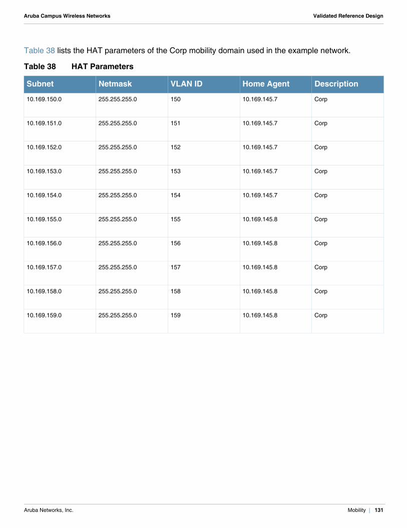
Aruba Campus Wireless Networks Validated Reference Design
Table 38 lists the HAT parameters of the Corp mobility domain used in the example network.
Table 38 HAT Parameters
Subnet Netmask VLAN ID Home Agent Description
10.169.150.0 255.255.255.0 150 10.169.145.7 Corp
10.169.151.0 255.255.255.0 151 10.169.145.7 Corp
10.169.152.0 255.255.255.0 152 10.169.145.7 Corp
10.169.153.0 255.255.255.0 153 10.169.145.7 Corp
10.169.154.0 255.255.255.0 154 10.169.145.7 Corp
10.169.155.0 255.255.255.0 155 10.169.145.8 Corp
10.169.156.0 255.255.255.0 156 10.169.145.8 Corp
10.169.157.0 255.255.255.0 157 10.169.145.8 Corp
10.169.158.0 255.255.255.0 158 10.169.145.8 Corp
10.169.159.0 255.255.255.0 159 10.169.145.8 Corp
Aruba Networks, Inc. Mobility | 131

Aruba Campus Wireless Networks Validated Reference Design
CLI Configuration
MC1-Sunnyvale-3600!
ip mobile domain Corp
description "for Corp users"
hat 10.169.150.0 255.255.255.0 150 10.169.145.7 description "Corp"
hat 10.169.151.0 255.255.255.0 151 10.169.145.7 description "Corp"
hat 10.169.152.0 255.255.255.0 152 10.169.145.7 description "Corp"
hat 10.169.153.0 255.255.255.0 153 10.169.145.7 description "Corp"
hat 10.169.154.0 255.255.255.0 154 10.169.145.7 description "Corp"
hat 10.169.155.0 255.255.255.0 155 10.169.145.8 description "Corp"
hat 10.169.156.0 255.255.255.0 156 10.169.145.8 description "Corp"
hat 10.169.157.0 255.255.255.0 157 10.169.145.8 description "Corp"
hat 10.169.158.0 255.255.255.0 158 10.169.145.8 description "Corp"
hat 10.169.159.0 255.255.255.0 159 10.169.145.8 description "Corp"
!
LC1-Sunnyvale-6000!
router mobile
ip mobile active-domain Corp
!
LC2-Sunnyvale-6000!
router mobile
ip mobile active-domain Corp
!
WebUI Screenshot
Figure 97 Mobility domain for MC1-Sunnyvale-3600
N O T E
Mobility is not enabled on the MC1-Sunnyvale-3600 controller, so while you configure the mobility domain on the master controller, ignore the following warning: *** WARNING ***: Mobility service is disabled (router mobile)
Aruba Networks, Inc. Mobility | 132
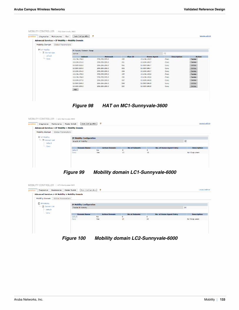
Aruba Campus Wireless Networks Validated Reference Design
Figure 98 HAT on MC1-Sunnyvale-3600
Figure 99 Mobility domain LC1-Sunnyvale-6000
Figure 100 Mobility domain LC2-Sunnyvale-6000
Aruba Networks, Inc. Mobility | 133

Aruba Campus Wireless Networks Validated Reference Design
Aruba Networks, Inc. Mobility | 134
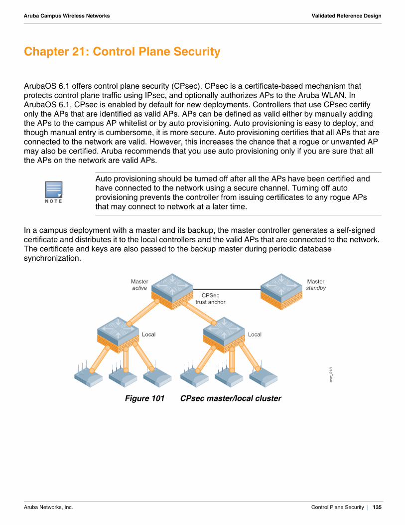
Aruba Campus Wireless Networks Validated Reference Design
Chapter 21: Control Plane Security
ArubaOS 6.1 offers control plane security (CPsec). CPsec is a certificate-based mechanism that protects control plane traffic using IPsec, and optionally authorizes APs to the Aruba WLAN. In ArubaOS 6.1, CPsec is enabled by default for new deployments. Controllers that use CPsec certify only the APs that are identified as valid APs. APs can be defined as valid either by manually adding the APs to the campus AP whitelist or by auto provisioning. Auto provisioning is easy to deploy, and though manual entry is cumbersome, it is more secure. Auto provisioning certifies that all APs that are connected to the network are valid. However, this increases the chance that a rogue or unwanted AP may also be certified. Aruba recommends that you use auto provisioning only if you are sure that all the APs on the network are valid APs.
In a campus deployment with a master and its backup, the master controller generates a self-signed certificate and distributes it to the local controllers and the valid APs that are connected to the network. The certificate and keys are also passed to the backup master during periodic database synchronization.
Figure 101 CPsec master/local cluster
N O T E
Auto provisioning should be turned off after all the APs have been certified and have connected to the network using a secure channel. Turning off auto provisioning prevents the controller from issuing certificates to any rogue APs that may connect to network at a later time.
arun_0411
CPSectrust anchor
Local Local
Masterstandby
Masteractive
Aruba Networks, Inc. Control Plane Security | 135
Aruba Campus Wireless Networks Validated Reference Design
Each master and local controller in the network that is a part of a CPsec chain has a campus AP whitelist that includes all the valid APs in the network, regardless of whether that AP is connected to it or not. The campus AP whitelist can be updated on any controller in the network. The changes in the whitelist on any controller are pushed to all other controllers in the network.
If a trust anchor fails in a CPsec-enabled network that has no master controller redundancy, you must address it immediately. If the trust anchor fails in a single master deployment, no more local controllers can be added to the network. However, if the failed trust anchor has to be replaced with a new controller, then all the controllers and APs should be recertified. Recertification requires that you reboot the controllers and APs, which disrupts the network.
Deploy a backup master controller to solve this issue. The database synchronization between the active and standby master ensures that keys and certificates are synced on the standby controller. Aruba strongly recommends that you deploy a backup controller for the CPsec trust anchor. Make sure that a database synchronization operation has occurred from primary master to backup at least once after the whole network is up and running. The synchronization ensures that all the certificates, keys, and whitelist entries that are required for CPsec are synced to the backup controller.
The example network has CPsec enabled and uses auto provisioning to validate the APs. Use auto provisioning only if you are confident that all the APs connected to the network are valid. If you are not sure, add the AP information manually. With auto provisioning, you can specify an IP range to which it will apply. For more information about CPsec, see the Aruba Mobility Controllers and Deployment Models Validated Reference Design.
CLI Configuration
MC1-Sunnyvale-3600!
control-plane-security
auto-cert-prov
no auto-cert-allow-all
auto-cert-allowed-addrs 10.169.145.20 10.169.145.254
!
!CAUTION
If a new controller is added to an existing deployment, make sure that the campus AP whitelist on the new controller is empty. This step is essential because any invalid AP information on the campus AP whitelist of the new controller is updated across all the controllers in the network.
!CAUTION
If you add a backup controller for the trust anchor in a CPsec environment, the backup controller must be added as the lower priority controller. If you add it as the higher priority controller, the CPsec keys and certificate of the current master may be lost.
Aruba Networks, Inc. Control Plane Security | 136
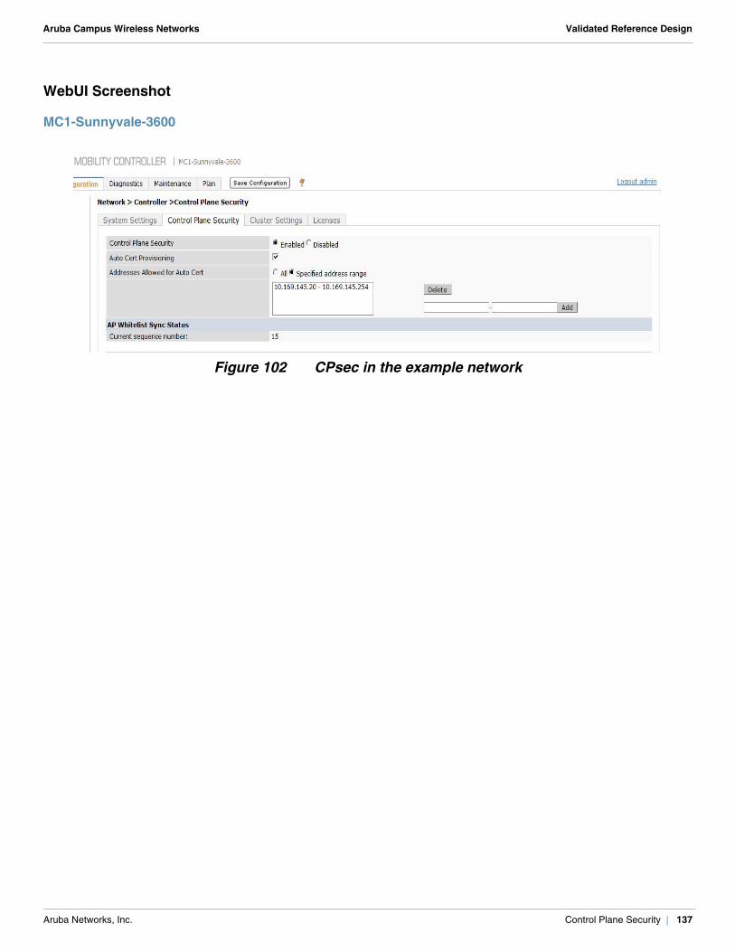
Aruba Campus Wireless Networks Validated Reference Design
WebUI Screenshot
MC1-Sunnyvale-3600
Figure 102 CPsec in the example network
Aruba Networks, Inc. Control Plane Security | 137

Aruba Campus Wireless Networks Validated Reference Design
Aruba Networks, Inc. Control Plane Security | 138
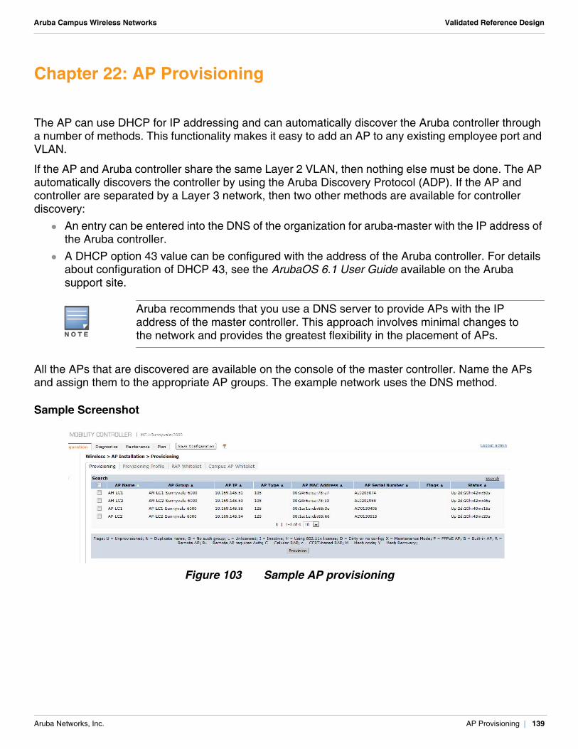
Aruba Campus Wireless Networks Validated Reference Design
Chapter 22: AP Provisioning
The AP can use DHCP for IP addressing and can automatically discover the Aruba controller through a number of methods. This functionality makes it easy to add an AP to any existing employee port and VLAN.
If the AP and Aruba controller share the same Layer 2 VLAN, then nothing else must be done. The AP automatically discovers the controller by using the Aruba Discovery Protocol (ADP). If the AP and controller are separated by a Layer 3 network, then two other methods are available for controller discovery:
An entry can be entered into the DNS of the organization for aruba-master with the IP address of the Aruba controller.
A DHCP option 43 value can be configured with the address of the Aruba controller. For details about configuration of DHCP 43, see the ArubaOS 6.1 User Guide available on the Aruba support site.
All the APs that are discovered are available on the console of the master controller. Name the APs and assign them to the appropriate AP groups. The example network uses the DNS method.
Sample Screenshot
Figure 103 Sample AP provisioning
N O T E
Aruba recommends that you use a DNS server to provide APs with the IP address of the master controller. This approach involves minimal changes to the network and provides the greatest flexibility in the placement of APs.
Aruba Networks, Inc. AP Provisioning | 139

Aruba Campus Wireless Networks Validated Reference Design
Aruba Networks, Inc. AP Provisioning | 140
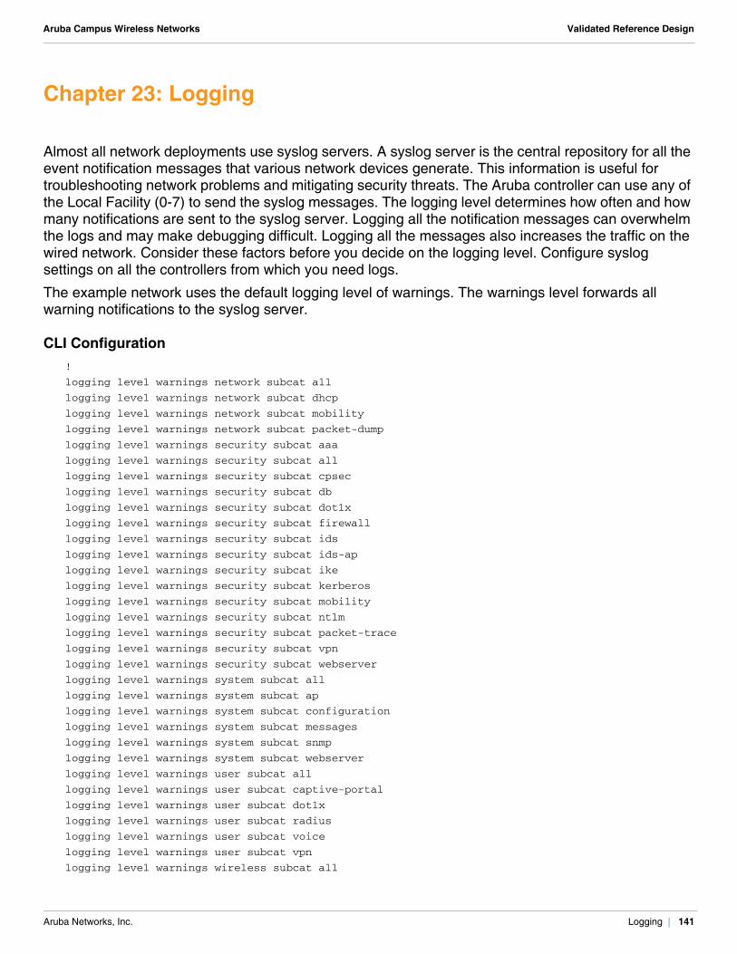
Aruba Campus Wireless Networks Validated Reference Design
Chapter 23: Logging
Almost all network deployments use syslog servers. A syslog server is the central repository for all the event notification messages that various network devices generate. This information is useful for troubleshooting network problems and mitigating security threats. The Aruba controller can use any of the Local Facility (0-7) to send the syslog messages. The logging level determines how often and how many notifications are sent to the syslog server. Logging all the notification messages can overwhelm the logs and may make debugging difficult. Logging all the messages also increases the traffic on the wired network. Consider these factors before you decide on the logging level. Configure syslog settings on all the controllers from which you need logs.
The example network uses the default logging level of warnings. The warnings level forwards all warning notifications to the syslog server.
CLI Configuration!
logging level warnings network subcat all
logging level warnings network subcat dhcp
logging level warnings network subcat mobility
logging level warnings network subcat packet-dump
logging level warnings security subcat aaa
logging level warnings security subcat all
logging level warnings security subcat cpsec
logging level warnings security subcat db
logging level warnings security subcat dot1x
logging level warnings security subcat firewall
logging level warnings security subcat ids
logging level warnings security subcat ids-ap
logging level warnings security subcat ike
logging level warnings security subcat kerberos
logging level warnings security subcat mobility
logging level warnings security subcat ntlm
logging level warnings security subcat packet-trace
logging level warnings security subcat vpn
logging level warnings security subcat webserver
logging level warnings system subcat all
logging level warnings system subcat ap
logging level warnings system subcat configuration
logging level warnings system subcat messages
logging level warnings system subcat snmp
logging level warnings system subcat webserver
logging level warnings user subcat all
logging level warnings user subcat captive-portal
logging level warnings user subcat dot1x
logging level warnings user subcat radius
logging level warnings user subcat voice
logging level warnings user subcat vpn
logging level warnings wireless subcat all
Aruba Networks, Inc. Logging | 141
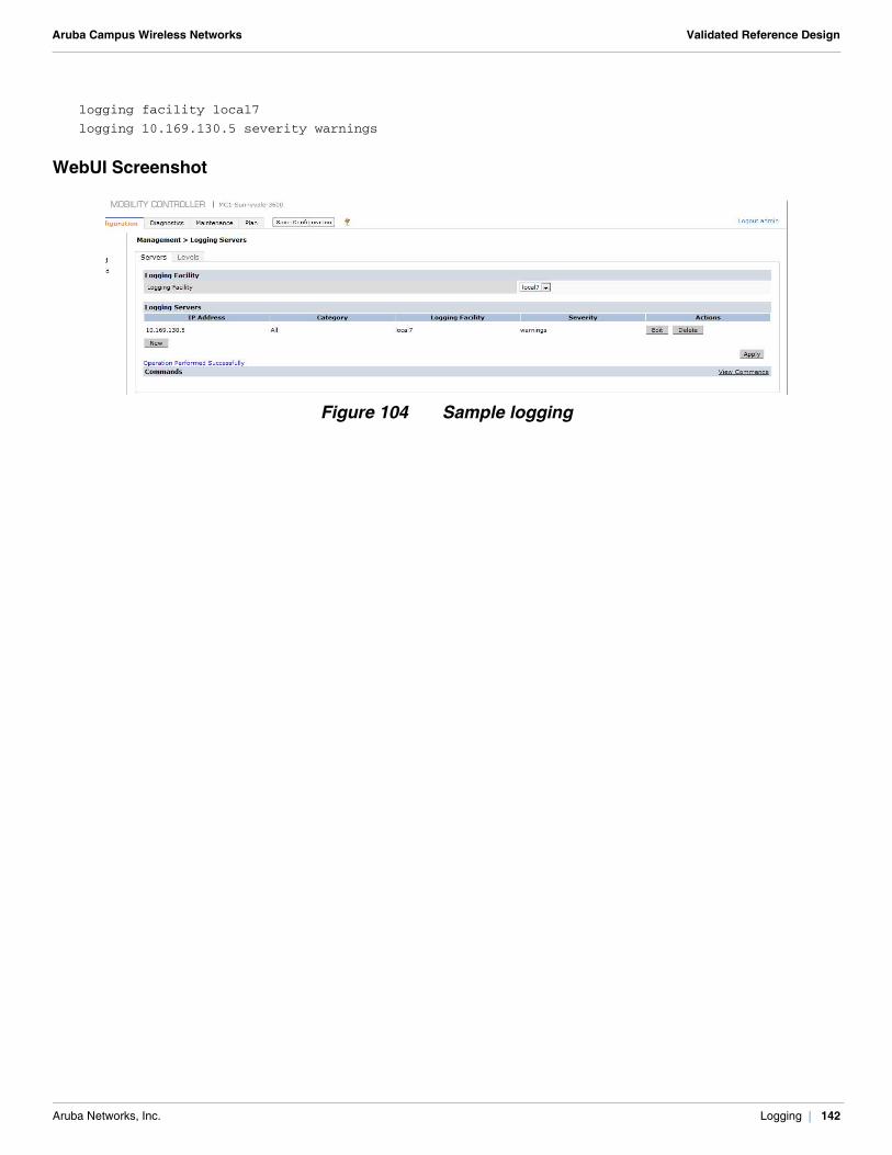
Aruba Campus Wireless Networks Validated Reference Design
logging facility local7
logging 10.169.130.5 severity warnings
WebUI Screenshot
Figure 104 Sample logging
Aruba Networks, Inc. Logging | 142
Aruba Campus Wireless Networks Validated Reference Design
Chapter 24: AirWave
As the network grows beyond a single master/local cluster, it becomes more complex to configure and troubleshoot. This complexity is increased further if more than a single cluster exists on the same campus, because users can easily roam between clusters. To simplify the job of the network administrator, use the AirWave system any time more than one master/local Aruba controller cluster exists in the network. The AirWave system provides a consolidated view of all components and users on the network in a single, flexible console. In addition to the functionality already present in the Aruba controllers, AirWave adds network-wide configuration, advanced reporting, and trending features. These additional features allow network administrators to interface with a single tool to plan, configure, and troubleshoot the network.
AirWave provides centralized configuration management, and allows network administrators to track client devices, identify rogue devices, plan new deployments, and visualize RF coverage patterns with an intuitive and seamless user interface. For more details about AirWave and how to set it up, see the AirWave7.2 User Guide available at the Aruba support site.
AirWave monitors Aruba devices using SNMP polling. The SNMP agent of the Aruba controllers must be set up to respond to these SNMP polls and send SNMP traps to AirWave. AirWave also requires Telnet or SSH credentials and the enable password to acquire license and serial information from controllers. Configure the SNMP settings on all the controllers that must be monitored by AirWave.
CLI Configuration!
snmp-server community public
snmp-server enable trap
snmp-server host 10.169.130.2 version 2c public udp-port 162
!
N O T E
The community string on the Aruba controllers must match that on AirWave.
Aruba Networks, Inc. AirWave | 143
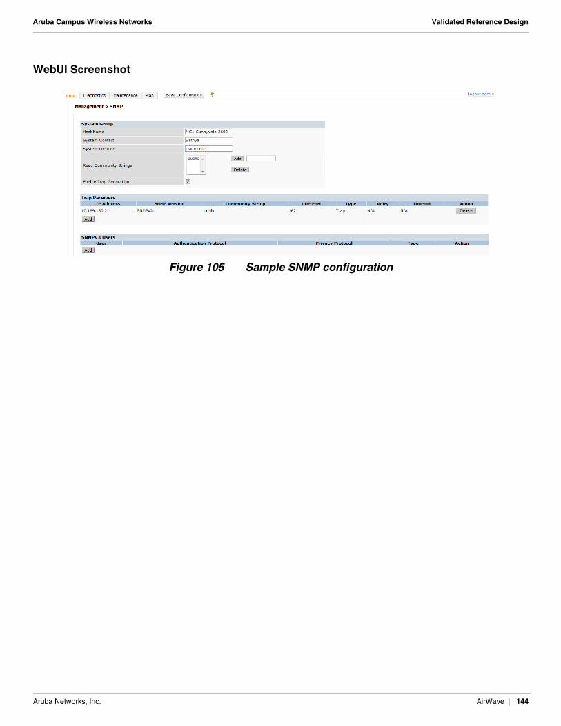
Aruba Campus Wireless Networks Validated Reference Design
WebUI Screenshot
Figure 105 Sample SNMP configuration
Aruba Networks, Inc. AirWave | 144
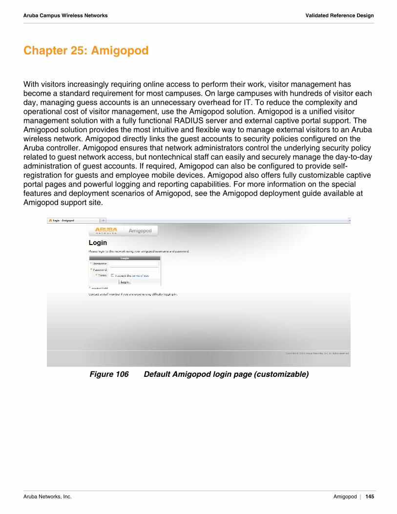
Aruba Campus Wireless Networks Validated Reference Design
Chapter 25: Amigopod
With visitors increasingly requiring online access to perform their work, visitor management has become a standard requirement for most campuses. On large campuses with hundreds of visitor each day, managing guess accounts is an unnecessary overhead for IT. To reduce the complexity and operational cost of visitor management, use the Amigopod solution. Amigopod is a unified visitor management solution with a fully functional RADIUS server and external captive portal support. The Amigopod solution provides the most intuitive and flexible way to manage external visitors to an Aruba wireless network. Amigopod directly links the guest accounts to security policies configured on the Aruba controller. Amigopod ensures that network administrators control the underlying security policy related to guest network access, but nontechnical staff can easily and securely manage the day-to-day administration of guest accounts. If required, Amigopod can also be configured to provide self-registration for guests and employee mobile devices. Amigopod also offers fully customizable captive portal pages and powerful logging and reporting capabilities. For more information on the special features and deployment scenarios of Amigopod, see the Amigopod deployment guide available at Amigopod support site.
Figure 106 Default Amigopod login page (customizable)
Aruba Networks, Inc. Amigopod | 145

Aruba Campus Wireless Networks Validated Reference Design
Aruba Networks, Inc. Amigopod | 146
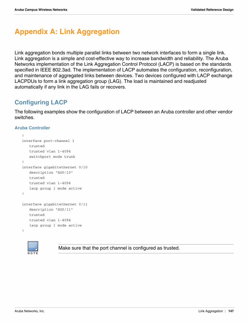
Aruba Campus Wireless Networks Validated Reference Design
Appendix A: Link Aggregation
Link aggregation bonds multiple parallel links between two network interfaces to form a single link. Link aggregation is a simple and cost-effective way to increase bandwidth and reliability. The Aruba Networks implementation of the Link Aggregation Control Protocol (LACP) is based on the standards specified in IEEE 802.3ad. The implementation of LACP automates the configuration, reconfiguration, and maintenance of aggregated links between devices. Two devices configured with LACP exchange LACPDUs to form a link aggregation group (LAG). The load is maintained and readjusted automatically if any link in the LAG fails or recovers.
Configuring LACPThe following examples show the configuration of LACP between an Aruba controller and other vendor switches.
Aruba Controller!
interface port-channel 1
trusted
trusted vlan 1-4094
switchport mode trunk
!
interface gigabitethernet 0/10
description "XG0/10"
trusted
trusted vlan 1-4094
lacp group 1 mode active
!
interface gigabitethernet 0/11
description "XG0/11"
trusted
trusted vlan 1-4094
lacp group 1 mode active
!
N O T E
Make sure that the port channel is configured as trusted.
Aruba Networks, Inc. Link Aggregation | 147
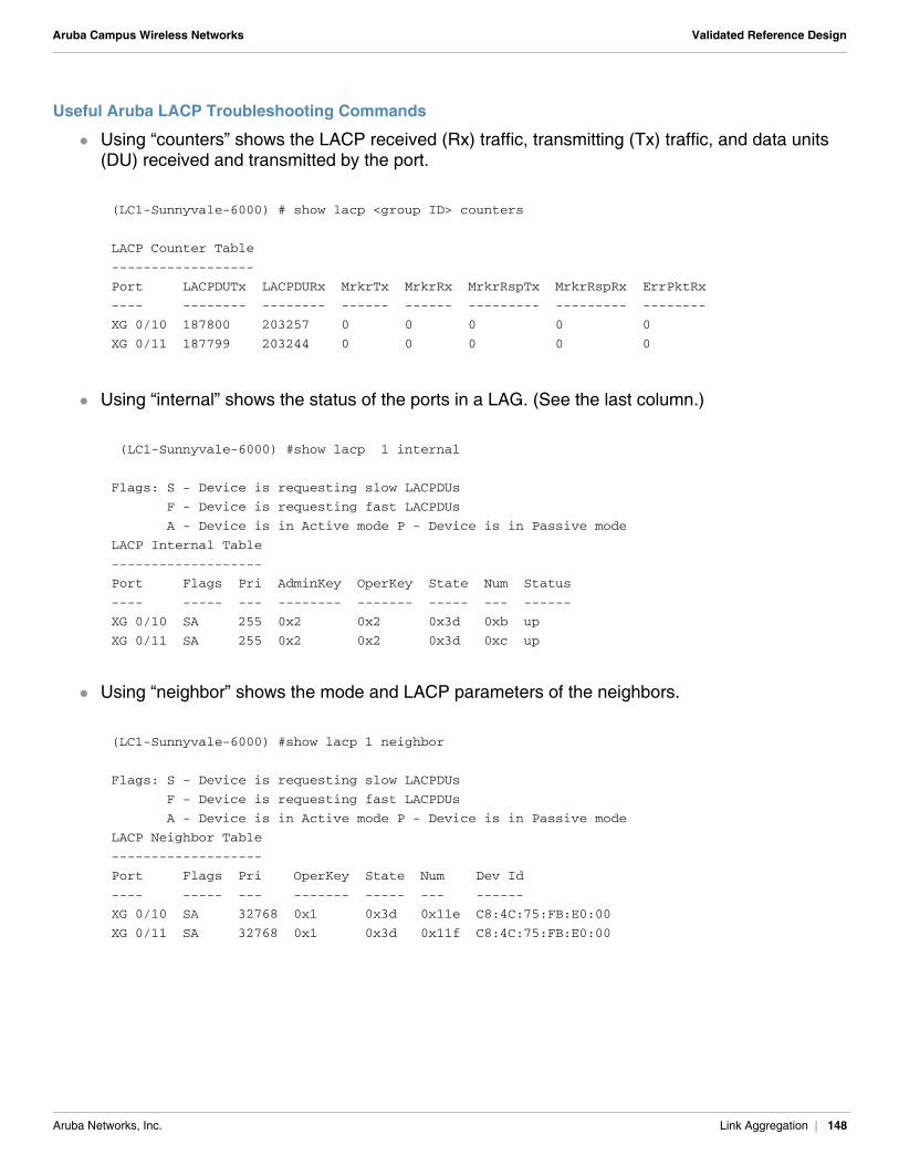
Aruba Campus Wireless Networks Validated Reference Design
Useful Aruba LACP Troubleshooting Commands
Using “counters” shows the LACP received (Rx) traffic, transmitting (Tx) traffic, and data units (DU) received and transmitted by the port.
Using “internal” shows the status of the ports in a LAG. (See the last column.)
Using “neighbor” shows the mode and LACP parameters of the neighbors.
(LC1-Sunnyvale-6000) # show lacp <group ID> counters
LACP Counter Table
------------------
Port LACPDUTx LACPDURx MrkrTx MrkrRx MrkrRspTx MrkrRspRx ErrPktRx
---- -------- -------- ------ ------ --------- --------- --------
XG 0/10 187800 203257 0 0 0 0 0
XG 0/11 187799 203244 0 0 0 0 0
(LC1-Sunnyvale-6000) #show lacp 1 internal
Flags: S - Device is requesting slow LACPDUs
F - Device is requesting fast LACPDUs
A - Device is in Active mode P - Device is in Passive mode
LACP Internal Table
-------------------
Port Flags Pri AdminKey OperKey State Num Status
---- ----- --- -------- ------- ----- --- ------
XG 0/10 SA 255 0x2 0x2 0x3d 0xb up
XG 0/11 SA 255 0x2 0x2 0x3d 0xc up
(LC1-Sunnyvale-6000) #show lacp 1 neighbor
Flags: S - Device is requesting slow LACPDUs
F - Device is requesting fast LACPDUs
A - Device is in Active mode P - Device is in Passive mode
LACP Neighbor Table
-------------------
Port Flags Pri OperKey State Num Dev Id
---- ----- --- ------- ----- --- ------
XG 0/10 SA 32768 0x1 0x3d 0x11e C8:4C:75:FB:E0:00
XG 0/11 SA 32768 0x1 0x3d 0x11f C8:4C:75:FB:E0:00
Aruba Networks, Inc. Link Aggregation | 148
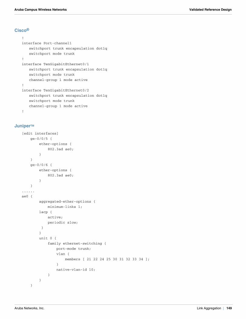
Aruba Campus Wireless Networks Validated Reference Design
Cisco®
!
interface Port-channel1
switchport trunk encapsulation dot1q
switchport mode trunk
!
interface TenGigabitEthernet0/1
switchport trunk encapsulation dot1q
switchport mode trunk
channel-group 1 mode active
!
interface TenGigabitEthernet0/2
switchport trunk encapsulation dot1q
switchport mode trunk
channel-group 1 mode active
!
JuniperTM
[edit interfaces]
ge-0/0/5 {
ether-options {
802.3ad ae0;
}
}
ge-0/0/6 {
ether-options {
802.3ad ae0;
}
}
......
ae0 {
aggregated-ether-options {
minimum-links 1;
lacp {
active;
periodic slow;
}
}
unit 0 {
family ethernet-switching {
port-mode trunk;
vlan {
members [ 21 22 24 25 30 31 32 33 34 ];
}
native-vlan-id 10;
}
}
}
Aruba Networks, Inc. Link Aggregation | 149
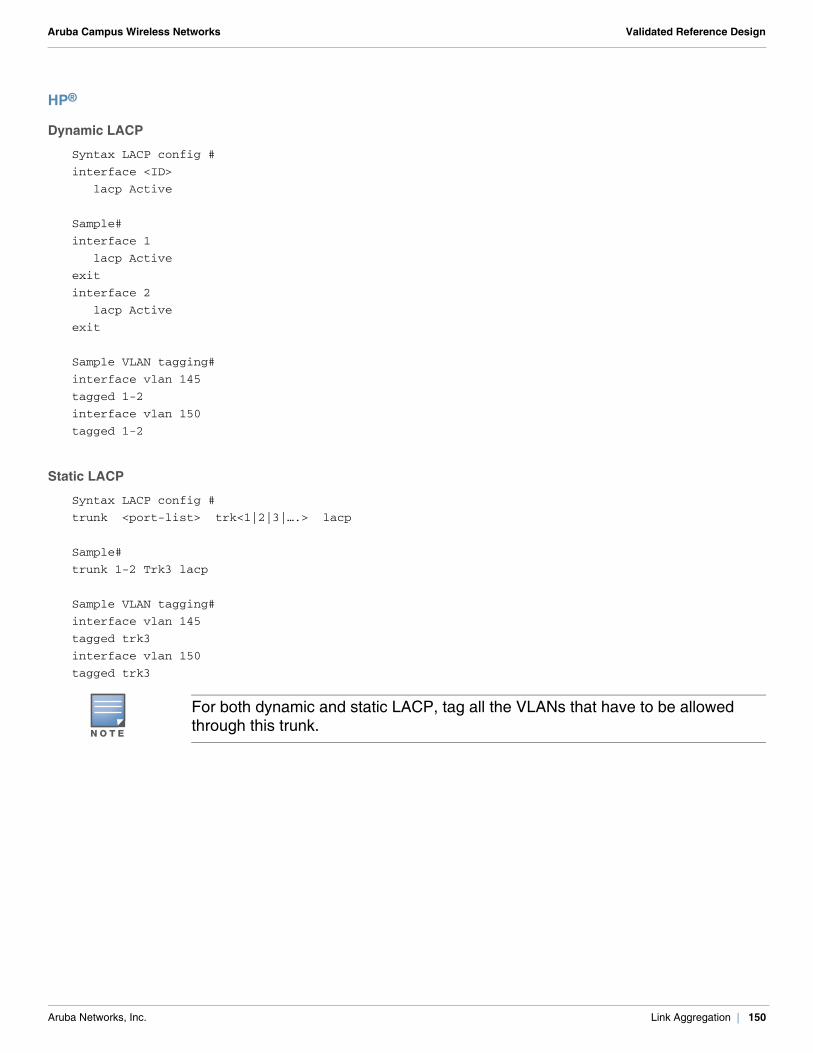
Aruba Campus Wireless Networks Validated Reference Design
HP®
Dynamic LACP
Syntax LACP config #
interface <ID>
lacp Active
Sample#
interface 1
lacp Active
exit
interface 2
lacp Active
exit
Sample VLAN tagging#
interface vlan 145
tagged 1-2
interface vlan 150
tagged 1-2
Static LACP
Syntax LACP config #
trunk <port-list> trk<1|2|3|….> lacp
Sample#
trunk 1-2 Trk3 lacp
Sample VLAN tagging#
interface vlan 145
tagged trk3
interface vlan 150
tagged trk3
N O T E
For both dynamic and static LACP, tag all the VLANs that have to be allowed through this trunk.
Aruba Networks, Inc. Link Aggregation | 150
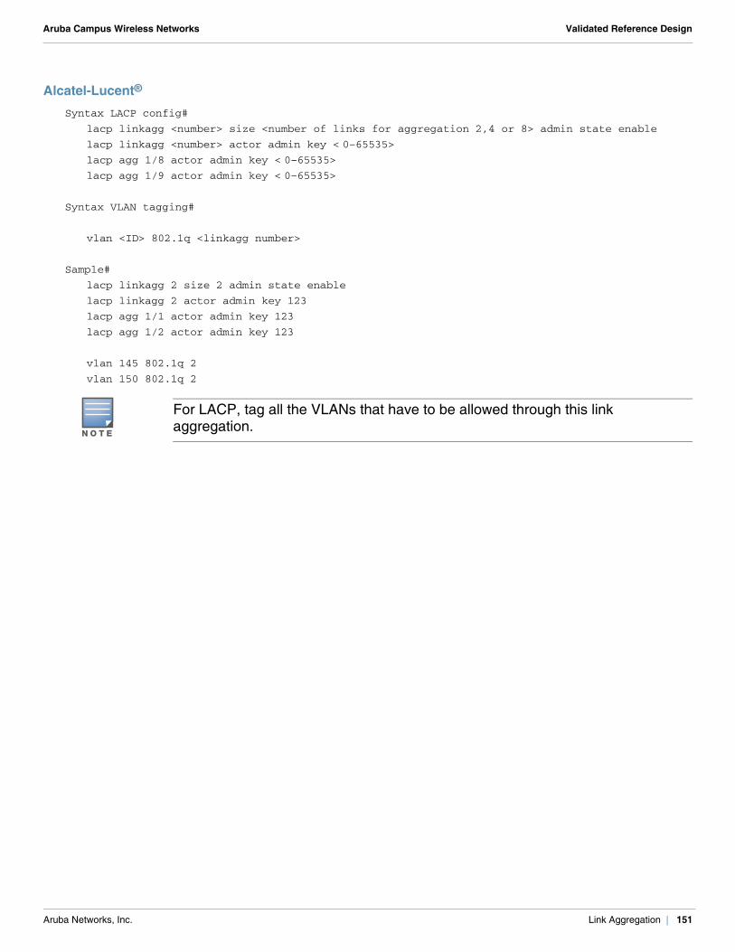
Aruba Campus Wireless Networks Validated Reference Design
Alcatel-Lucent®
Syntax LACP config#
lacp linkagg <number> size <number of links for aggregation 2,4 or 8> admin state enable
lacp linkagg <number> actor admin key < 0–65535>lacp agg 1/8 actor admin key < 0–65535>lacp agg 1/9 actor admin key < 0–65535>
Syntax VLAN tagging#
vlan <ID> 802.1q <linkagg number>
Sample#
lacp linkagg 2 size 2 admin state enable
lacp linkagg 2 actor admin key 123
lacp agg 1/1 actor admin key 123
lacp agg 1/2 actor admin key 123
vlan 145 802.1q 2
vlan 150 802.1q 2
N O T E
For LACP, tag all the VLANs that have to be allowed through this link aggregation.
Aruba Networks, Inc. Link Aggregation | 151

Aruba Campus Wireless Networks Validated Reference Design
Aruba Networks, Inc. Link Aggregation | 152
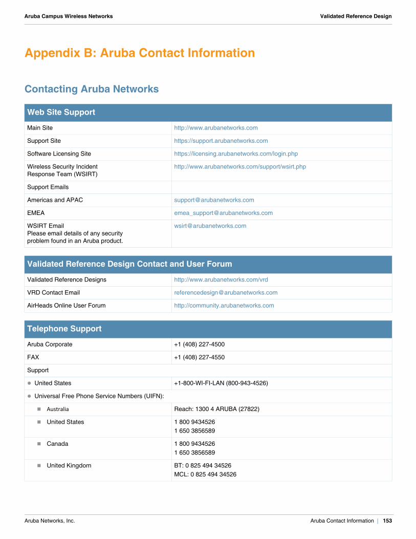
Aruba Campus Wireless Networks Validated Reference Design
Appendix B: Aruba Contact Information
Contacting Aruba Networks
Web Site Support
Main Site http://www.arubanetworks.com
Support Site https://support.arubanetworks.com
Software Licensing Site https://licensing.arubanetworks.com/login.php
Wireless Security IncidentResponse Team (WSIRT)
http://www.arubanetworks.com/support/wsirt.php
Support Emails
Americas and APAC [email protected]
EMEA [email protected]
WSIRT EmailPlease email details of any securityproblem found in an Aruba product.
Validated Reference Design Contact and User Forum
Validated Reference Designs http://www.arubanetworks.com/vrd
VRD Contact Email [email protected]
AirHeads Online User Forum http://community.arubanetworks.com
Telephone Support
Aruba Corporate +1 (408) 227-4500
FAX +1 (408) 227-4550
Support
United States +1-800-WI-FI-LAN (800-943-4526)
Universal Free Phone Service Numbers (UIFN):
Australia Reach: 1300 4 ARUBA (27822)
United States 1 800 94345261 650 3856589
Canada 1 800 94345261 650 3856589
United Kingdom BT: 0 825 494 34526MCL: 0 825 494 34526
Aruba Networks, Inc. Aruba Contact Information | 153
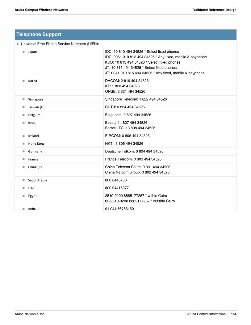
Aruba Campus Wireless Networks Validated Reference Design
Universal Free Phone Service Numbers (UIFN):
Japan IDC: 10 810 494 34526 * Select fixed phonesIDC: 0061 010 812 494 34526 * Any fixed, mobile & payphoneKDD: 10 813 494 34526 * Select fixed phonesJT: 10 815 494 34526 * Select fixed phonesJT: 0041 010 816 494 34526 * Any fixed, mobile & payphone
Korea DACOM: 2 819 494 34526KT: 1 820 494 34526ONSE: 8 821 494 34526
Singapore Singapore Telecom: 1 822 494 34526
Taiwan (U) CHT-I: 0 824 494 34526
Belgium Belgacom: 0 827 494 34526
Israel Bezeq: 14 807 494 34526Barack ITC: 13 808 494 34526
Ireland EIRCOM: 0 806 494 34526
Hong Kong HKTI: 1 805 494 34526
Germany Deutsche Telkom: 0 804 494 34526
France France Telecom: 0 803 494 34526
China (P) China Telecom South: 0 801 494 34526China Netcom Group: 0 802 494 34526
Saudi Arabia 800 8445708
UAE 800 04416077
Egypt 2510-0200 8885177267 * within Cairo02-2510-0200 8885177267 * outside Cairo
India 91 044 66768150
Telephone Support
Aruba Networks, Inc. Aruba Contact Information | 154