Artisan Technology Group is your source for quality ...€¦ · 6.8 Conversion Factors 22 ......
31
Artisan Technology Group is your source for quality new and certified-used/pre-owned equipment • FAST SHIPPING AND DELIVERY • TENS OF THOUSANDS OF IN-STOCK ITEMS • EQUIPMENT DEMOS • HUNDREDS OF MANUFACTURERS SUPPORTED • LEASING/MONTHLY RENTALS • ITAR CERTIFIED SECURE ASSET SOLUTIONS SERVICE CENTER REPAIRS Experienced engineers and technicians on staff at our full-service, in-house repair center WE BUY USED EQUIPMENT Sell your excess, underutilized, and idle used equipment We also offer credit for buy-backs and trade-ins www.artisantg.com/WeBuyEquipment REMOTE INSPECTION Remotely inspect equipment before purchasing with our interactive website at www.instraview.com LOOKING FOR MORE INFORMATION? Visit us on the web at www.artisantg.com for more information on price quotations, drivers, technical specifications, manuals, and documentation Contact us: (888) 88-SOURCE | [email protected] | www.artisantg.com SM View Instra
-
Upload
truonghanh -
Category
Documents
-
view
220 -
download
1
Transcript of Artisan Technology Group is your source for quality ...€¦ · 6.8 Conversion Factors 22 ......

Artisan Technology Group is your source for quality new and certified-used/pre-owned equipment
• FAST SHIPPING AND DELIVERY
• TENS OF THOUSANDS OF IN-STOCK ITEMS
• EQUIPMENT DEMOS
• HUNDREDS OF MANUFACTURERS SUPPORTED
• LEASING/MONTHLY RENTALS
• ITAR CERTIFIED SECURE ASSET SOLUTIONS
SERVICE CENTER REPAIRSExperienced engineers and technicians on staff at our full-service, in-house repair center
WE BUY USED EQUIPMENTSell your excess, underutilized, and idle used equipment We also offer credit for buy-backs and trade-inswww.artisantg.com/WeBuyEquipment
REMOTE INSPECTIONRemotely inspect equipment before purchasing with our interactive website at www.instraview.com
LOOKING FOR MORE INFORMATION? Visit us on the web at www.artisantg.com for more information on price quotations, drivers, technical specifications, manuals, and documentation
Contact us: (888) 88-SOURCE | [email protected] | www.artisantg.com
SMViewInstra

MODEL 370 OPTOMETER
P/N 79-10-032 Revision D January 1993
UDT Instruments 8581 Aero Drive San Diego, CA 92123
Tel: (877)532-5800 Fax:(858)576-9286
Artisan Technology Group - Quality Instrumentation ... Guaranteed | (888) 88-SOURCE | www.artisantg.com
www.udtinstruments.com
8581 Aero Drive – San Diego, CA 92123 ● U.S-A ● (877) 532-5800 ● Fax (858) 576-9286
Product Warranty Warranty Provisions
UDT Instruments warrants the items delivered hereunder to be free from defects in material and workmanship, and to conform to current UDT Instruments specifications at the time of sale. Purchaser shall have a period of one year from date of acceptance of the items to return deficient items to UDT Instruments for correction. Material will be considered accepted 30 days after receipt by purchaser unless UDT Instruments is notified of acceptance earlier.
UDT Instruments agrees to repair or replace at the
place of manufacture, without charge, all items returned, transportation prepaid, for inspection at the UDT Instruments factory within the warranty period, provided: (1) such inspection discloses to the satisfaction of UDT Instruments that the defects are as above specified; and, (2) the material has not been subjected to misuse, improper maintenance, negligence or accident, damaged by excessive radiation, voltage, current or otherwise damaged by misuse.
The item returned shall only be accepted when
accompanied by a written statement setting forth the nature and suspected cause of the alleged deficiencies.
This warrant is expressly in lieu of all other
warranties, express, implied or statutory, and all other obligations or liabilities on the part of UDT Instruments. In no event shall UDT Instruments be liable for claims, demands or damages of any nature, however denominated, except that UDT Instruments liability shall be to repair defective items at its factory, or supply replacement parts in accordance with the terms of this warranty.
When equipment is shipped FOB UDT Instrument's
factory, and when said equipment fails to perform according to specifications upon receipt, a claim should be made immediately against the shipping agency.
SHIPMENT AND PAYMENT UDT Instruments payment terms are NET 30 days.
Shipment will be made FOB Baltimore, Maryland. Warranty Return Procedures
Note: If this device has warranty and calibration seals, all warranties and calibrations are void if these seals are broken.
1. Please review terms of purchase and date of
shipment to determine if product is warranted and whether or not it is within warranty period. Adjustment cannot be made for product out of warranty.
2. If product is subject to warranty, prior to
return of product, telephone, write or fax UDT Instruments at the above address.
Product malfunctions should be reported to the
Sales Department at the earliest possible time, since there are many occasions when technical assistance may obviate the need for returning products or can prevent product damage. Upon verification that warranty service is required, the Sales Department will issue a Return Material Authorization number (RMA number). The RMA number must appear on the outside of the shipping container for proper receipt.
3. It is necessary in all instances that the "return
report" form be completed. Please photocopy and fill out the return report located in your product manual.
4 Repack the product carefully in the same
manner it was originally packaged, preferably using the original shipping carton and packaging material. Pack the completed "return report" with the product making sure the RMA number is clearly visible on the outside of the container. Ship the product prepaid to UDT Instruments.
5. UDT Instruments will advise your company of
its' findings as to warranty consideration at the earliest possible time.
Artisan Technology Group - Quality Instrumentation ... Guaranteed | (888) 88-SOURCE | www.artisantg.com

www.udtinstruments.com
8581 Aero Drive - San Diego, CA 92123 ● U.S-A ● (800) 637-2758 ● Fax (858) 576-9286
ADDENDUM: CE MARK EXCLUSIONS
1. The instrument is not intended for use in high humidity, high pollution, or explosive environments.
2. The instrument and related accessories are "CE" compliant when operated in the
manufacturer's recommended configuration, and in accordance with the exclusions described in this addendum. UDT Instruments does not accept responsibility for "CE" compliance if the instrument is used in a non-recommended configuration.
3. All semiconductor devices are susceptible to electrostatic discharges (ESD). Ensure that
the unit is switched off before connecting or disconnecting any cable(s) or accessories. Failure to do so can cause "ESD" damage and reduce the lifetime of the instrument drastically.
4. Units with ieee-488 capability must use a shielded cable; similar to Hewlett-Packard part
number HP10833x or Io-Tech part number CA-7-X, to maintain compliance.
5. All coaxial cables must be less than 3 meters long.
6. All battery-operated units have batteries that are not replaceable by the customer, and can only be charged with the battery charger supplied with the unit by UDT Instruments.
7. Cleaning: Special care must be used when cleaning the instrument. The body, or any
labels, should only be cleaned with a soft damp cloth, and a very light concentration of mild soap. Failure to do so may scratch the surface or damage any anti-glare coatings.
Never use alcohol, acetone, or other chemical solvents to clean any part of the unit.
Artisan Technology Group - Quality Instrumentation ... Guaranteed | (888) 88-SOURCE | www.artisantg.com

CONTENTS
Page
CAUTIONS 2
SPECIFICATIONS 3
1.0 GENERAL INFORMATION 4
1.1 Introduction 4 1.2 Applications 4 1.3 Accessories 5 1.4 Calibration 5 2.0 PREPARATOIM FOR USE 5 2.1 Inspection 5 2.2 Instrument Identification 6 2.3 Input Power Requirements 6 2.4 Packaging for Shipment 6 3.0 OPERATION 6
3.1 Front Panel Control 6 3.2 IEEE-488 Interface 8 3.3 Data Format 11 3.4 Typical Operation 11 4.0 THEORY OF OPERATION 12 5.0 USER ADJUSTMENT, PERFORMANCE 13 VERIFICATION AND CALIBRATION
INFORMATION 5.1 LCD Viewing Angle 13 5.2 Performance Verification 13 5.3 Calibration Data Format 13 6.0 USERS GUIDE 15 6.1 Introduction 15 6.2 Illuminance Measurements 16 6.3 CW Laser Power Measurements 17 6.4 Luminance Measurements 19 6.5 Miscellaneous Measurements 20 6.6 Bibliography 21 6.7 Formulas 21 6.8 Conversion Factors 22 FIGURES E. 1 – E. 7 24
Artisan Technology Group - Quality Instrumentation ... Guaranteed | (888) 88-SOURCE | www.artisantg.com
MODEL 370 REV: D Page 2 of 26
CAUTION
Each Model 370 is calibrated at the factory for specific detector and accessories included with the instrument. Do not substitute different detector or accessories without verifying that the calibration is installed in the instrument.
The maximum input power level for this instrument, assuming only a radiometric filter is used, is 10mW total or 500mW/ cm2, whichever is less. Beyond these flux levels the detector becomes nonlinear. Beyond 10mW total or 500mW/cm2 there is a risk of irreversible detector damage.
Verify proper line voltage selection prior to operation. See the rear panel switch for line voltage. Attempted operation at incorrect line voltage will cause catastrophic damage.
Disconnect AC line prior to removal of top cover to avoid electrical shock or accidental damage.
Artisan Technology Group - Quality Instrumentation ... Guaranteed | (888) 88-SOURCE | www.artisantg.com

MODEL 370 REV: D Page 3 of 26
SPECIFICATIONS
Display Alphanumeric 16 x 2 lines, character liquid crystal, display update rate 2 to 4 readings/second, 4 to 5 significant digits displayed; contrast adjustment provided on rear of display, switch selective electroluminescent backlighting.
Controls: 10 touch sensitive controls set instrument function, also programmable through IEEE-488 interface.
Push-button power on/off with red LED power indicator.
Calibration: Calibration information stored in rear panel mounted EPROM. EPROM contains current measurement calibration for pico-ammeter function and calibration information on specified detectors.
Digital Interface: Removable front panel BNC connector modules provided for detector connections.
Power Required: 90-132VAC or 180-264VAC 47-440Hz, switch selected on rear panel, 12 VA max required. Fused at 1/8 A for 115VAC operation, 1/16 A for 230VAC operation. Uses low blow fuses. Accepts 3AG, 0.25” (6mm) diameter x 1.25” (31mm) long fuses. Male IEC line connector provided. Rear panel DC input 9 to 15 VDC, 500mA max, not switched. Mating connector is Switchcraft type 760.
Dimensions: 3.69” (94mm) H x 8.5” (216mm) W x 9.25” (235mm) D.
Weight: 4.0 pounds (1.8Kg)
Operating Temperature Range: 0ºC to 45ºC
Storage Temperature Range: -20ºC to 60ºC
A/D Converter: Resolution: 15 bits plus sign
Full Scale Voltage: 2.5V
Sampling Rate: 2 to 4 readings per second
Trans-impedance Amplifier System:
Gain Ranges: 10 to 10 V/A, decade steps
Input Current Error, Temperature Drift: 2pA max, doubles every 10ºC
Input Voltage Error: 10µV max over temp.
Maximum Operational Input Current: 1.5mA
Maximum safe input current: 7.5mA
Artisan Technology Group - Quality Instrumentation ... Guaranteed | (888) 88-SOURCE | www.artisantg.com
MODEL 370 REV: D Page 4 of 26
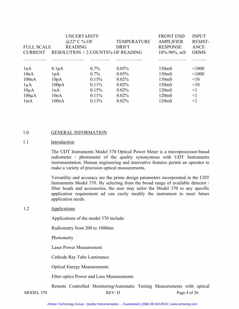
UNCERTAINTY FRONT END INPUT @22º C % OF TEMPERATURE AMPLIFIER RESIST- FULL SCALE READING DRIFT RESPONSE ANCE CURRENT RESOLUTION + 2 COUNTS% OF READING 10%-90%, mS OHMS __________ ______________ ________ ___________ ____________ ______ 1nA 0.1pA 0.7% 0.05% 150mS <1000 10nA 1pA 0.7% 0.05% 150mS <1000 100nA 10pA 0.15% 0.02% 150mS <10 1µA 100pA 0.11% 0.02% 150mS <10 10µA 1nA 0.15% 0.02% 120mS <1 100µA 10nA 0.11% 0.02% 120mS <1 1mA 100nA 0.13% 0.02% 120mS <1
1.0 GENERAL INFORMATION
1.1 Introduction
The UDT Instruments Model 370 Optical Power Meter is a microprocessor-based radiometer / photometer of the quality synonymous with UDT Instruments instrumentation. Human engineering and innovative features permit an operator to make a variety of precision optical measurements.
Versatility and accuracy are the prime design parameters incorporated in the UDT Instruments Model 370. By selecting from the broad range of available detector / filter heads and accessories, the user may tailor the Model 370 to any specific application requirement ad can easily modify the instrument to meet future application needs.
1.2 Applications
Applications of the model 370 include:
Radiometry from 200 to 1800nm
Photometry
Laser Power Measurement
Cathode Ray Tube Luminance
Optical Energy Measurements
Fiber optics Power and Loss Measurements
Remote Controlled Monitoring/Automatic Testing Measurements with optical
Artisan Technology Group - Quality Instrumentation ... Guaranteed | (888) 88-SOURCE | www.artisantg.com

MODEL 370 REV: D Page 5 of 26
Equipment such as Scanning Monochromators
1.3 Accessories
The instrument is designed to accept all standard UDT Instruments Radiometric /Photometric accessories including microphotometer and telephotometer attachments, radiometric and photometric detector head assemblies, visible and infrared LED measurement systems, integrating spheres for attenuation and uniform response, detectors with smaller active areas, low profile head assemblies for tight spaces, and special bandpass filters for UV through near infrared measurements.
1.4 Calibration
Detector assemblies may be obtained with calibrations stored in a plug-in calibration (PIC) EPROM. Stored information includes data for calibrations with standard filters and accessories for radiometric or photometric measurements, special filters, or specialized detector assemblies for measurements at particular wavelengths such as 632.8nm for HeNe lasers, or continuous calibration data covering a wide spectral range. If accessories are obtained after initial purchase, either the PIC module can be returned for calibration additions or a new one purchased.
Calibration data includes calibration certification listing model and serial numbers of items calibrated, description of calibration including wavelength, measurement units, special accessories or conditions, and a statement of traceability to NBS. UDT Instruments maintains standards and equipment optimized for accurate calibration and recalibration of instruments. The normal period to recalibration is six months. An electrical calibration lab may have the facilities to check the current measurement accuracy of the 370 (See performance verification). In this case only the detector assemblies and PIC modules need be returned for calibration.
UDT Instruments keeps calibration data for each instrument on file.
2.0 PREPARATION FOR USE
2.1 Inspection
Before shipment this instrument was inspected and found to be free of defects. When unpacking, inspect for damage that may have occurred during shipment. If damage is found, file a claim with the carrier and notify the UDT Instruments customer service department.
The Model 370 shipping container should contain:
1 – Model 370 Optometer
1 – Instruction Manual
1 – Carrying Case
Artisan Technology Group - Quality Instrumentation ... Guaranteed | (888) 88-SOURCE | www.artisantg.com

MODEL 370 REV: D Page 6 of 26
1 – Plug in Calibration Module
A/R – Detector Assemblies Ordered Separately
2.2 Instrument Identification
The instrument’s model and serial numbers are on a label on the rear panel. The instrument history is maintained in a serial number file at UDT Instruments.
2.3 Input Power Requirements
The instrument operates on 90-132VAC or 180-264VAC 47-440Hz, 10VA nominal.
Line voltage is selected by a switch on the rear panel power supply circuit board.
The instrument is fused at 1/8 AMP for 1154VAC, 1/16 AMP for 230VAC.
Verify proper line voltage and fuse rating prior to operating the instrument.
2.4 Packaging for Shipment The carrying case supplied with the instrument is intended to be used as a shipping, carrying, and storage case. It is recommended that this case be used when returning the instrument for repair and recalibration.
3.0 OPERATION
This section describes the switch functions and basic operation of the Model 370. Stand alone operation and use of the IEEE-488 interface is described. For an introduction to measurements see the “User’s Guide”.
3.1 Front Panel Controls
3.1.1 Power
Turns on the instrument. The display shows the message “UDT Instruments Model S370”
3.1.2 The following touch sensitive switches perform:
Halt Instrument Function Display Status of Indicated Channel Item being Changed is underlined
Autorange/Manual: Changes the range control from auto to manual range or manual range to auto range. When in manual range the gain may be changed by pressing the up/down keys.
Function: Allows selection of measurement type, the first push displays the present status, additional pushes change the function selected to the next one.
Artisan Technology Group - Quality Instrumentation ... Guaranteed | (888) 88-SOURCE | www.artisantg.com

MODEL 370 REV: D Page 7 of 26
Linear: For normal average measurements.
Log Ratio: For logarithmic average ratio measurements of the signal to the previous measurement, which is saved when using this function. To change the reference value, change mode to linear, start measurement, adjust signal and change the mode back to log ratio.
Ratio: Performs linear ratio of the signal to the previous measurement, which is automatically stored when using this function. To change the reference value, change mode to linear, start measurement, adjust signal and change the mode back to log ratio.
Responsivity/User Entered Responsivity: Displays the set responsivity. Pushing the start/stop key moves cursor from left to right. Pushing up/down key changes values at cursor (sign, value and measurement units). When the last character is set, pushing start/stop key will display measurement units which can then be changed. Analog/Digital: Changes the digital reading to analog reading or analog reading to digital reading. When in analog reading, the scale factor may be changed by pushing the up/down keys. Display returns to the normal scale when start/stop is pushed twice.
Calibration Select: Pushing calibration select displays calibration.
Typical Display: 268R S/N 17790
The message, usually containing the detector model number, serial number. Other Calibrations are obtained by pressing the up/down key.
Wavelength Select: The calibration status is displayed.
Calibrations at other wavelengths may be obtained by using the up/down keys. The keys will scroll through the available wavelengths with auto repeat if held down.
Zero: Saves previous readings for subtraction from following readings. A cursor will appear on the right side of the display. To implement the zero function, push the zero switch again, a “z” will appear on the right side of the display. The cursor or “z” will not be displayed if the start/stop key is pressed following the zero procedure. To change back to a non-zeroed measurement, press the zero key so that the cursor is obtained on the right side of the display.
If the measurement function is log ratio or ratio, pressing zero in half mode will display the value of the reference signal.
Start/Stop: Begins or halts the measurement cycle. Pushing start clears the display and begins measurement.
Artisan Technology Group - Quality Instrumentation ... Guaranteed | (888) 88-SOURCE | www.artisantg.com
MODEL 370 REV: D Page 8 of 26
Display Illumination: Turns the display back light on or off.
3.2 IEEE-488 Interface
3.2.1 The IEEE interface allows communications between the instrument, a talker/listener, and a controller such as a Hewlett Packard desk top computer equipped with the HPIB interface or any system with an IEEE-488 interface.
As a listener, the instrument terminates communication when ASCII line feed (LF) or end or identify (EOI) is received. Carriage return, commonly sent by HP systems is received and ignored.
Talking is terminated with CRLF, EOI is sent with the last character.
3.2.2 Device Address The Device address is factory set to address code 04. The address code may be changed by resetting dip switch 1 (IEEE address SW1) accessed through the rear panel. Then resetting is accomplished by turning the power off and the on again after the display has gone blank. The address is determined by converting the desired address (0 to 31) to a binary number. For example, the binary value for the factory-set address of 4 is 001000. Use the tip of a pen or a small tool to set the switches.
3.2.3 IEEE Control Codes
The following codes sent via the IEEE bus set the instrument functions. The codes perform the same functions as obtainable from the front panel except that Up/Down key presses are replaced with numbers representing the desired values.
IEEE bus commands “LLO”, “GTL”, and “SDC” may also be sent to set the instrument in local lockout (front panel controls disabled) and go to local (front panel controls enabled), and send device clear. Local lockout is useful to prevent interference with bus operation by accidental contact with the front panel.
3.2.4 Typical Bus Operation
The following examples indicate typical operation of the IEEE bus using a HP-85 computer. Characters are interpreted from left to right and are set as upper case ASCII character strings.
OUTPUT 704 ; “K3W700M7G”
Sets for third calibration from EPROM at wavelength of 700nm, manual range = 7, and go.
OUTPUT 704 ; “K”
Artisan Technology Group - Quality Instrumentation ... Guaranteed | (888) 88-SOURCE | www.artisantg.com
MODEL 370 REV: D Page 9 of 26
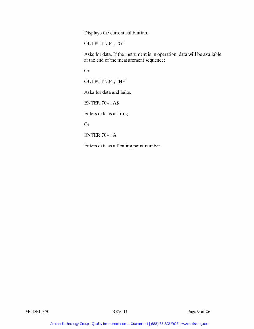
Displays the current calibration.
OUTPUT 704 ; “G”
Asks for data. If the instrument is in operation, data will be available at the end of the measurement sequence;
Or
OUTPUT 704 ; “HF”
Asks for data and halts.
ENTER 704 ; A$
Enters data as a string
Or
ENTER 704 ; A
Enters data as a floating point number.
Artisan Technology Group - Quality Instrumentation ... Guaranteed | (888) 88-SOURCE | www.artisantg.com

MODEL 370 REV: D Page 10 of 26
TABLE 1
IEEE CONTROL CODES A Set Autorange B0 restore screen B1 blank screen B2 Turn on backlight B3 Turn off backlight D set mode, DL log, DN linear, DR ratio, DG logratio. E0 digital reading E1 analog bar reading F send current reading Data is equal to input current divided by responsitivity G Go H Halt K Display Caldata Kx select Caldata x M set Manual mode, does not change range Mx set gain to specific exponent 3, 4, 5, 6, 7, 8, 9 R Send responsivity; R+x.xxxE+xx set responsivity S send status of current channel to controller. Format is MODE WAVELENGTH
AUTO/MANUAL GAIN with each datapoint separated by space (ASCII 2Ōh) U ask for Unit of measure V1 -set unit to W V2 - set unit to fc V3 - set unit to Lux V4 - set unit to f V5 - set unit to W/cm2 V6 - set unit to W/cm2*sr V7 - set unit to Cd/m2 V8 - set unit to Lm WX set Wavelength 200 to 2000 depending on cal WU Increments current wavelength by current step WD Decrements current wavelength by current step X display status of current channel ZX set Zero mode, Z to turn on zero mode, Z1 to reset zero mode *MESSAGE* displays “message” where message is an ASCII String of up to 16 characters
Artisan Technology Group - Quality Instrumentation ... Guaranteed | (888) 88-SOURCE | www.artisantg.com

MODEL 370 REV: D Page 11 of 26
3.3 Data Format
The format of the data string consists of fourteen characters:
±D.DDDDE+DD_S
The first twelve characters are data in floating point notation with five significant digits plus sign, following the E is the exponent which is two significant characters plus sign.
The fourteenth characters is a space, separating the status character. These characters are ignored if the data has been entered as a floating point number.
The status character, S indicates
O Overrange – data points have exceeded the full scale range of the A/D converter.
P Previously read – This data has been outputted before.
N Normal – valid new data.
U Undefined – result of indefinable calculation
3.4 Typical Operation
Typical operation requires calibration selection for each channel, optional selections are: manual range control, auto zero, and function.
3.4.1 Select calibration. Measurements may also be calculated externally. Set the instrument for current measurement and calculate the power by dividing the current in amps by the responsivity in amps per unit of measure/
3.4.2 Check that the detector assembly serial mumber agrees with the serial number of the detector assembly in the calibration status display. Connect the detector to the BNC connector on the rear panel of the instrument.
3.4.3 If the calibration has continuous calibration data, the wavelength of interest should be selected.
3.4.4 Measurements will begin when the start button is pressed. The message “OVERRANGE” will be displayed when the full scale value of the A/D converter is exceeded. The autorange function will normally locate the best measurement range. A message “Undefined” will occur if a divide by zero or log of negative number calculation has been attempted.
3.4.5 Optional Selections
3.4.5.1 Manual/Autorange Initial selection is for autoranging. A change to manual ranging may be helpful if a time varying signal causes the display to flash, indicating
Artisan Technology Group - Quality Instrumentation ... Guaranteed | (888) 88-SOURCE | www.artisantg.com
MODEL 370 REV: D Page 12 of 26
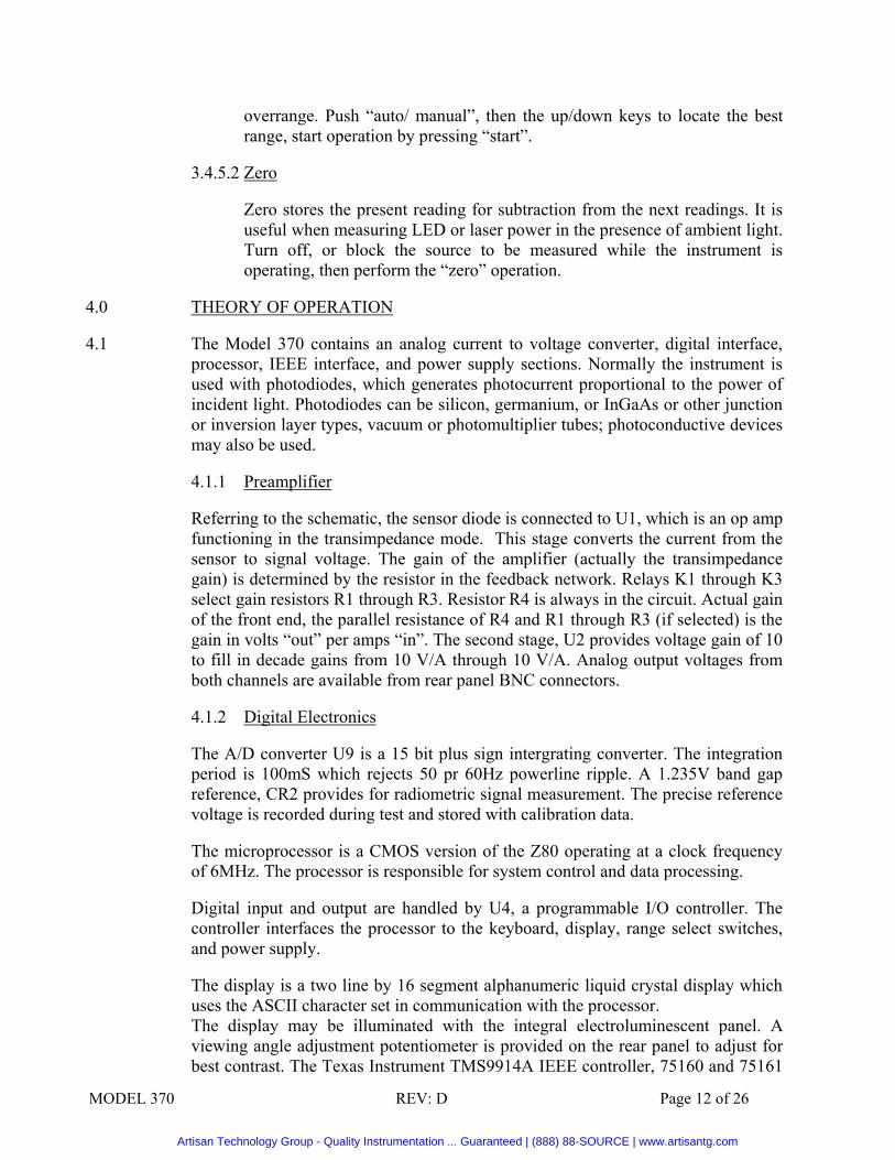
overrange. Push “auto/ manual”, then the up/down keys to locate the best range, start operation by pressing “start”.
3.4.5.2 Zero
Zero stores the present reading for subtraction from the next readings. It is useful when measuring LED or laser power in the presence of ambient light. Turn off, or block the source to be measured while the instrument is operating, then perform the “zero” operation.
4.0 THEORY OF OPERATION
4.1 The Model 370 contains an analog current to voltage converter, digital interface, processor, IEEE interface, and power supply sections. Normally the instrument is used with photodiodes, which generates photocurrent proportional to the power of incident light. Photodiodes can be silicon, germanium, or InGaAs or other junction or inversion layer types, vacuum or photomultiplier tubes; photoconductive devices may also be used.
4.1.1 Preamplifier
Referring to the schematic, the sensor diode is connected to U1, which is an op amp functioning in the transimpedance mode. This stage converts the current from the sensor to signal voltage. The gain of the amplifier (actually the transimpedance gain) is determined by the resistor in the feedback network. Relays K1 through K3 select gain resistors R1 through R3. Resistor R4 is always in the circuit. Actual gain of the front end, the parallel resistance of R4 and R1 through R3 (if selected) is the gain in volts “out” per amps “in”. The second stage, U2 provides voltage gain of 10 to fill in decade gains from 10 V/A through 10 V/A. Analog output voltages from both channels are available from rear panel BNC connectors.
4.1.2 Digital Electronics
The A/D converter U9 is a 15 bit plus sign intergrating converter. The integration period is 100mS which rejects 50 pr 60Hz powerline ripple. A 1.235V band gap reference, CR2 provides for radiometric signal measurement. The precise reference voltage is recorded during test and stored with calibration data.
The microprocessor is a CMOS version of the Z80 operating at a clock frequency of 6MHz. The processor is responsible for system control and data processing.
Digital input and output are handled by U4, a programmable I/O controller. The controller interfaces the processor to the keyboard, display, range select switches, and power supply.
The display is a two line by 16 segment alphanumeric liquid crystal display which uses the ASCII character set in communication with the processor. The display may be illuminated with the integral electroluminescent panel. A viewing angle adjustment potentiometer is provided on the rear panel to adjust for best contrast. The Texas Instrument TMS9914A IEEE controller, 75160 and 75161
Artisan Technology Group - Quality Instrumentation ... Guaranteed | (888) 88-SOURCE | www.artisantg.com

MODEL 370 REV: D Page 13 of 26
interface buffers provide I/W communications through the IEEE 488 interface.
Switch SW1 at the rear panel determines the IEEE bus address for the instrument. Binary coding is read during power on initialization.
4.1.3 Software
At power on, a start up routine initialixes the system and displays the power on message.
The displayed readings are calculated from:
A/D data (binary) * 2 * Vref * Calibration * A/unit Linear = —————————————————————
32678 * Gain V/A
Logarithmic readings are calculated using Log10 Software. All data values are calculated using floating point routines.
4.1.4 Power Supply Circuitry
The standard IEC line connector P10, fuse F1 and line voltage selector switch SW2 provide AC voltage to power transformer T1. Isolated low voltage AC from the transformer is rectified, filtered, and regulated to 5VDC by diodes CR5, CR6, Capacitor C7, and U5. U19, a power supply inverter, provides -5V for the analog circuitry.
5.0 USER ADJUSTMENT, PERFORMANCE VERIFICATION, AND CALIBRATION INFORMATION
Sections 5.1 and 5.2 describe adjustments and measurements to verify the performance of the Model 37. Section 5.3 describes the calibration data format in the EPROM
5.1 LCD Viewing Angle
The viewing angle of the LCD display may be adjusted by turning the potentiometer on the rear of the instrument. Adjust the potentiometer for best contrast and viewing angle.
5.2 Performance Verification
The accuracy of the Model 370 may be verified using a precision current source such as a Keithley Model 220 or equivalent. The Model 370 will change range as the signal causes the display to increase beyond 24000 counts. Verify accuracy by comparison of indicated currents to the accuracy table in the specifications section.
5.3 Calibration Data Format Calibration information is stored in the 32K x 8 EPROM starting at hex memory
address 6000 in standard Intel hex format. The format of the calibration EPROM is as follows:
Artisan Technology Group - Quality Instrumentation ... Guaranteed | (888) 88-SOURCE | www.artisantg.com

MODEL 370 REV: D Page 14 of 26
No. Description Type Bytes 1. Number of cals C 1 2. System Voltage Reference B 8 3. Germanium C 1 4. Unit B 8 5. Message 1 B 16 6. Message 2 B 16 7. Start of Wavelength A 2 8. End of Wavelength A 2 9. Step of Wavelength A 2 10. Address for Next Cal C 2 11. Address for Previous Cal C 2 12. Cal Data floting point, use minus for common B 10 per Cathode and conventional current measurement.
Calibration Note: Repeat numbers 3 to 12 for next cals.
A. For single wavelength: - wavelength step = 10, - start wavelength = wavelength For calibration without wavelength information, set start wavelength Th = 0.
B. Hex Representation of ASCII Character. C. Hex Integer
The following is an example calibration.
00 01 02 03 04 05 06 07 08 09 0A 0B 0C 0D 0E 0F ASCII-CODE 6000 04 31 2E 32 32 37 30 20 20 00 57 30 35 34 36 41 1.2272…70546A 6010 00 00 57 00 00 00 00 00 00 00 34 35 30 2D 39 35 ..W…….450-95 6020 30 20 6E 6D 00 00 00 00 00 00 32 36 32 20 53 2F 0 nm……262 S/ 6030 4E 20 32 35 31 32 00 00 00 00 00 00 00 00 0A 00 N 2512………. 6040 4E 60 D8 60 2D 2E 31 34 35 36 00 00 00 00 00 37 N. - .1456……7 6050 30 35 34 36 42 00 00 57 00 00 00 00 00 00 00 34 0546B. . W…4 6060 35 30 2D 39 35 30 20 6E 6D 00 00 00 00 00 00 32 50-950 NM 2 6070 36 32 20 53 2F 4E 20 32 35 32 30 00 00 00 00 00 62 S/N 2520... 6080 00 00 00 0A 00 93 60 09 60 2D 2E 31 33 37 37 00 …’ . ’ -. 1377. 6090 00 00 00 00 41 4D 50 45 52 45 53 00 41 00 00 00 AMPERES.A 60A0 00 00 00 00 50 4F 53 49 54 49 56 45 20 43 55 52 POSOTOVE CUR 60B0 52 45 4E 54 50 4F 53 49 54 49 56 45 20 43 55 52 PENTPOSITIVE
CUR 60C0 52 45 4E 54 00 00 00 00 0A 00 D8 60 4E 60 31 2E RENT ……N 1. 60D0 30 30 30 30 00 00 00 00 00 41 4D 50 45 52 45 53 0000 AMPERES 60E0 00 41 00 00 00 00 00 00 00 4E 45 47 41 54 49 56 A…NEGATIV 60F0 45 20 43 55 52 52 45 4E 54 4E 45 47 41 54 49 56
ECURRENTNEGATIV 6100 45 20 43 55 52 52 45 4E 54 00 00 00 00 0A 00 09 E CURRENT………. 6110 60 93 60 2D 31 2E 30 30 30 30 00 00 00 00 00 00 …..-1.0000…………. 6120 00
Artisan Technology Group - Quality Instrumentation ... Guaranteed | (888) 88-SOURCE | www.artisantg.com
MODEL 370 REV: D Page 15 of 26
6.0 USERS GUIDE
6.1 Introduction
The purpose of this guide is to describe the most common applications and how typical measurements should be performed with the UDT Instruments Radiometers.
The instrument is extremely versatile and has been ergonomically engineered for ease of use. The instrument typically uses a 1cm silicon planar diffused detector which is extremely rugged and stable. This stability permits calibrations to be held for very long periods for time and permits very low noise, sensitive, linear and accurate measurements to be routinely performed. UDT Instruments detectors are sensitive from 350 to 1100 nm (200 nm – 1100 nm for special UV-enhanced detectors with quarts window), can measure power typically from picowatts (10-12 watts) to milliwatts (10-3 watts) and even to many watts with the appropriate accessories.
6.1.1 Calibrations
Before using the Instrument refer to the detector/instrument calibration sheet. This tells precisely how the particular instrument was calibrated, the units, the channels used, as well as any multiplication factors. This calibration sheet is fundamental to the proper use of the instrument.
In addition to the calibrations listed on the data sheet, almost any meaningful instrument calibration can be performed by the UDT Instruments Optical Metrology Department.
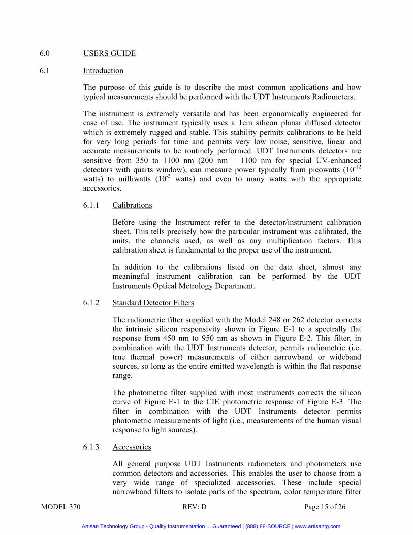
6.1.2 Standard Detector Filters
The radiometric filter supplied with the Model 248 or 262 detector corrects the intrinsic silicon responsivity shown in Figure E-1 to a spectrally flat response from 450 nm to 950 nm as shown in Figure E-2. This filter, in combination with the UDT Instruments detector, permits radiometric (i.e. true thermal power) measurements of either narrowband or wideband sources, so long as the entire emitted wavelength is within the flat response range.
The photometric filter supplied with most instruments corrects the silicon curve of Figure E-1 to the CIE photometric response of Figure E-3. The filter in combination with the UDT Instruments detector permits photometric measurements of light (i.e., measurements of the human visual response to light sources).
6.1.3 Accessories
All general purpose UDT Instruments radiometers and photometers use common detectors and accessories. This enables the user to choose from a very wide range of specialized accessories. These include special narrowband filters to isolate parts of the spectrum, color temperature filter
Artisan Technology Group - Quality Instrumentation ... Guaranteed | (888) 88-SOURCE | www.artisantg.com

MODEL 370 REV: D Page 16 of 26
sets to measure the blackbody temperature of incandescent sources, red photometric filters to precisely match the red response of the human eye, fiber optic probes, reflex viewing modules to convert the radiometer into a teleradiometer or microradiometer and many other accessories.
In addition special head assemblies are available which allow the user to measure ultraviolet light precisely, as well as heads for measuring Helium-Neon laser compliance and light emitting diode output.
The UDT Instruments optional accessories brochure describes the complete range of accessories.
6.2 Illuminance Measurements
6.2.1 Purspose
To measure the illuminance of a source such as the illumination level in an office or factory or photographic exposure times.
6.2.2 Equipment
A - Radiometer/Photometer Indicator Unit
B - detector and cable
C - photometric filter (Model 111)
D - diffuser (Model 112)
6.2.3 Procedure
1. Connect the instrument to the detector using the cable supplied.
2. Attach the photometric filter onto the detector housing with the filter between the detector and limiting aperture and attach diffuser onto the filter.
3. Position the head as desired to make the measurement. The conventional measurement of illumination is done with the head positioned at the work plane pointing vertically upwards (see Figure E-4).
4. Make sure that the measurement is not affected by the shadows from the operator or any other obstacles. The diffuser “sees” objects up to 90º away from the aiming direction.
5. Refer to the calibration sheet. This will indicate which channel should be used, what multiplication factors are applicable, and what attachments or other conditions apply. (Normally illuminance measurements are made with a diffuser, however sometimes illuminance measurements are done without the diffuser when high
Artisan Technology Group - Quality Instrumentation ... Guaranteed | (888) 88-SOURCE | www.artisantg.com
MODEL 370 REV: D Page 17 of 26
sensitivity is required and when the source is within the detector acceptance angle.
6. Follow the zeroing procedure outlined in the operating section of the manual.
7. Adjust the range switch until a non-full scale reading is obtained. When measuring time varying sources it is advisable to view the analog output (on instruments so equipped) with an oscilloscope to ensure that the fron end amplifier does not saturate.
8. See Section 7.0 for formulas relating exposure in lux-seconds to film speed.
6.2.4 Typical Measurement Units
- Footcandles (lumen/ft2)
- lux (lumen/m2)
6.3 CW Laser Power Measurements
6.3.1 Purpose
To determine the total power in a CW laser beam, irradiance from a CW laser, or irradiance from any other CW light source.
6.3.2 Equipment
A - Radiometer/Photometer Indicator Unit
B - detector and cable
C - radiometric filter
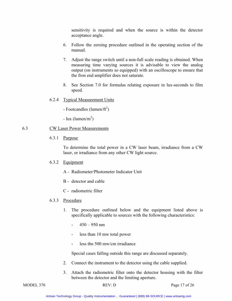
6.3.3 Procedure
1. The procedure outlined below and the equipment listed above is specifically applicable to sources with the following characteristics:
- 450 – 950 nm
- less than 10 mw total power
- less thn 500 mw/cm irradiance
Special cases falling outside this range are discussed separately.
2. Connect the instrument to the detector using the cable supplied.
3. Attach the radiometric filter onto the detector housing with the filter between the detector and the limiting aperture.
Artisan Technology Group - Quality Instrumentation ... Guaranteed | (888) 88-SOURCE | www.artisantg.com

MODEL 370 REV: D Page 18 of 26
4. Position the head in the laser beam or in the measurement field. (See Figure E-5.)
5. Refer to the calibration sheet. This will indicate which channel should be used, what multiplication factors are applicable and what attachments or other conditions apply.
6. Follow the zeroing procedure outlined in the operating manual.
7. Adjust the range switch until a non-full scale reading is obtained.
8. Verify that the radiant flux and irradiance are less than the values stated in step 1.
9. Adjust the detector head in translation and also in tilt while observing the meter, in order to verify that the beam is fully on the detector and no unusual shadowing is taking place.
6.3.4 Typical Measurement Units
- W, mW - W/cm2, mW/cm2
6.3.5 Procedure For Use With Narrow-band Light Sources Outside the Range 450-950nm
The set-up described above can be used for sources outside the 450-950nm range but inside the range 300-1100nm with the following procedure.
1. Obtain a single point calibration from UDT Instruments for use without the radiometric filter at the wavelength of interest.
2. Delete the radiometric filter from the test setup and take the reading as outlined above but using the single point calibration.
6.3.6 Procedure For Use With a Light Source Greater Than 10mw or Greater than 500mw/sq cm Irradiance
By adding one or more of the accessories listed below the measurement range can be extended by the multiplication factor indicated.
Model # Description Multiplier Comment
105 ND 1 filter 10 May cause inaccuracies because of multiple reflections (0.5W max).
105 ND 2 filter 100 May cause inaccuracies because of multiple reflections (0.5W max).
107 ND 3 filter 1000 May cause inaccuracies because of
Artisan Technology Group - Quality Instrumentation ... Guaranteed | (888) 88-SOURCE | www.artisantg.com

MODEL 370 REV: D Page 19 of 26
multiple reflections (0.5W max).
2500 Laser Integrating Sphere 1,000 Not spectrally flat, needs single point calibration (100W max).
2525 LED Integrating Sphere 1,000 Not spectrally flat, needs single point calibration (10W max).
2550 Laser Attentuator 100 Not spectrally flat, needs single point calibration (0.5W max).
2575 Mini Integrating Sphere 500 Not spectrally flat, needs single point calibration (10W max).
Refer to the option accessories brochure for the description of the attenuators.
1. Attach the attenuator as shown in Figure E-5.
2. Perform the measurement as outlined in Section 6.3.3.
6.4 Luminance Measurements (Also Radiance, Luminous And Radiant Intensity)
6.4.1 Purpose
To Measure the Luminance (or radiance) of extended sources such as projection screens, cathode ray tubes, etc. (Also to measure the luminous or radiant intensity of a point source).
6.4.2 Equipment
A – UDT Instruments Indicator Unit
B – detector and cable
C – photometric filter (Model 111)
D – 15º lumilens (Model 1153)
6.4.3 Procedure
1. Connect the instrument to the detector using the cable supplied.
2. Screw the photometric filter onto the detector housing and screw the lumilens onto the filter.
3. Point the head towards the extended source as shown in Figure E-6
4. Make sure that the source is uniform and subtends at least a 15º angle at the detector.
5. Refer to the calibration sheet. This will indicate which channel should be used, what multiplication factors and what attachments or other conditions apply.
Artisan Technology Group - Quality Instrumentation ... Guaranteed | (888) 88-SOURCE | www.artisantg.com

MODEL 370 REV: D Page 20 of 26
6. Follow the zeroing procedure outlined in the operating section of the manual.
7. Adjust the range switch until a non-full-scale reading is obtained. When measuring time varying sources it is advisable to view the analog output (on instruments so equipped) with an oscilloscope to insure that the front end amplifier does not saturate.
8. For luminance measurements or sources smaller than 15º use the 1120 reflex viewing module.
6.4.4 Typical Measurement Units (SI unit)
nit (candela/m2) [cd/m2]
stilb (candela/ m2) [cd/m2]
apostilb (1/π candela/ m2) [1/π cd/m2]
lambert (1/π candela/cm2) [1/π cd/m2]
candela/ft2 [π footlamber]
footlambert (3.426 candela/m2) [1/π cd/ft2]
6.4.5 Procedure for Radiance
Perform the same procedure as outlined in Section 6.4.2 but with the radiometric filter in place of the photometric filter. Typical units will be watts/cm2-sr.
6.4.6 Procedure for Luminous or Radiant Intensity
Perform the same procedure as outlined in Sections 6.4.2 and 6.4.3 above using the photometric filter for luminous intensity, the radiometric filter for radiant intensity and substituting a point source which subtends less than a 15º angle at the detector in place of the extended source.
Typical units will be:
- Candela (lumen/sr)
- Watt/sr
6.5 Miscellaneous Measurements
Utilizing the procedures outlined above, numerous other measurements may be performed. A few representative examples are listed below.
6.5.1 LED Measurements
Artisan Technology Group - Quality Instrumentation ... Guaranteed | (888) 88-SOURCE | www.artisantg.com

MODEL 370 REV: D Page 21 of 26
By using either the UDT Instruments Model 129 LED shade or by making a laboratory setup as shown in Figure E-7 the luminous or radiant intensity of an LED or lamp may be measured. The procedure is similar to that of Section 6.3.
6.5.2 Transmission and Absorption Measurements
By interposing a sample between the light source and detector, the transmission or absorption of a sample may be measured.
6.6 Bibliography
IES Lighting Handbook, Kaufman & Christensen, Illuminating Engineering Society, 345 E. 47th St. New York, N.Y. 10017
The Optical Industry and Systems Directory Compiled and Edited by the Optical Publishing Co., Inc., P.O. Box 1146 Pittsfield, MS 01201
Focal Encyclopedia of Photography, ed. By F. Purves, Focal Press Ltd. 31 Fitzroy Square, London, W.1
Radiometric Calibration: Theory and Methods, Clair L. Wyatt, Academic Press, 111 Fifth Avenue New York, NY 10003
Handbook of Lasers with Selected Data on Optical Technology ed. by Robert J. Pressley, The Chemical Rubber Company 18901 Cranwood Parkway Cleveland, OH 44128
Color Science, Wyszecki & Stiles, John Wiley & Sons, Inc., NY
6.6 Formulas
1. Speed of Photographic Materials E = Film exposure for an acceptable print measured in
lux-sec)
ASA index = 1/(4E)
DIN index = (10 log E) -5
2. Illumination of camera image plane
Artisan Technology Group - Quality Instrumentation ... Guaranteed | (888) 88-SOURCE | www.artisantg.com

MODEL 370 REV: D Page 22 of 26
B = brightness of object measured in candelas/sq.ft.
I = illumination on camera image plane in footcandles. = B/(4(f#)
2)
Illumination at object plane if camera is removed and film placed directly at location of camera image plane
= B (footcandles) = 10.76 B (lux)
6.8 Conversion Factors
LUMINANCE (PHOTOMETRIC BRIGHTNESS) CONVERSION FACTORS
1 NIT = 1 CANDELA/SQUARED METER
1 STILB = 1 CANDELA/SQUARED CENTIMETER
1 APOSTILB (INTERNATIONAL) = 0.1 MILLILAMBERT = 1 BLONDEL
1 APOSTILB (GERMAN HEFNER) = 0.09 MILLILAMBERT
1 LAMBERT = 1000 MILLILAMBERTS
Multiply number of To Obtain By foot- Candela milli- candela/ candela/ Number of lambert sq. m. lambert sq.in. sq.ft. stilb
footlambert 1 0.2919 0.929 452 3.143 2,919
candela/sq.m. 3.426 1 3.183 1,550 10.76 10,000
millilambert 1.076 0.3142 1 487 3.382 3,142
candela/sq.in. 0.00221 0.000645 0.000205 1 0.00694 6.45
candela/sq.ft. 0.3183 0.0929 0.2957 144 1 929
stilb 0.00034 0.0001 0.00032 0.155 0.00108 1
Artisan Technology Group - Quality Instrumentation ... Guaranteed | (888) 88-SOURCE | www.artisantg.com
MODEL 370 REV: D Page 23 of 26
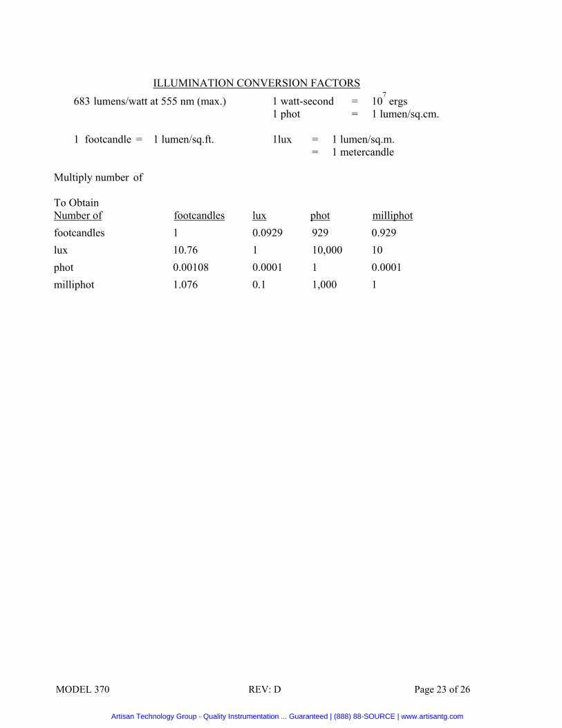
ILLUMINATION CONVERSION FACTORS
683 lumens/watt at 555 nm (max.) 1 watt-second = 107 ergs
1 phot = 1 lumen/sq.cm.
1 footcandle = 1 lumen/sq.ft. 1lux = 1 lumen/sq.m. = 1 metercandle Multiply number of To Obtain Number of footcandles lux phot milliphot footcandles 1 0.0929 929 0.929 lux 10.76 1 10,000 10 phot 0.00108 0.0001 1 0.0001 milliphot 1.076 0.1 1,000 1
Artisan Technology Group - Quality Instrumentation ... Guaranteed | (888) 88-SOURCE | www.artisantg.com

MODEL 370 REV: D Page 24 of 26
Artisan Technology Group - Quality Instrumentation ... Guaranteed | (888) 88-SOURCE | www.artisantg.com

MODEL 370 REV: D Page 25 of 26
Artisan Technology Group - Quality Instrumentation ... Guaranteed | (888) 88-SOURCE | www.artisantg.com

MODEL 370 REV: D Page 26 of 26
Artisan Technology Group - Quality Instrumentation ... Guaranteed | (888) 88-SOURCE | www.artisantg.com

Artisan Technology Group is your source for quality new and certified-used/pre-owned equipment
• FAST SHIPPING AND DELIVERY
• TENS OF THOUSANDS OF IN-STOCK ITEMS
• EQUIPMENT DEMOS
• HUNDREDS OF MANUFACTURERS SUPPORTED
• LEASING/MONTHLY RENTALS
• ITAR CERTIFIED SECURE ASSET SOLUTIONS
SERVICE CENTER REPAIRSExperienced engineers and technicians on staff at our full-service, in-house repair center
WE BUY USED EQUIPMENTSell your excess, underutilized, and idle used equipment We also offer credit for buy-backs and trade-inswww.artisantg.com/WeBuyEquipment
REMOTE INSPECTIONRemotely inspect equipment before purchasing with our interactive website at www.instraview.com
LOOKING FOR MORE INFORMATION? Visit us on the web at www.artisantg.com for more information on price quotations, drivers, technical specifications, manuals, and documentation
Contact us: (888) 88-SOURCE | [email protected] | www.artisantg.com
SMViewInstra